EP2840633B1 - Lithium-Akku auf Lithiumeisenphosphat und Kohlenstoffbasis - Google Patents
Lithium-Akku auf Lithiumeisenphosphat und Kohlenstoffbasis Download PDFInfo
- Publication number
- EP2840633B1 EP2840633B1 EP14184728.5A EP14184728A EP2840633B1 EP 2840633 B1 EP2840633 B1 EP 2840633B1 EP 14184728 A EP14184728 A EP 14184728A EP 2840633 B1 EP2840633 B1 EP 2840633B1
- Authority
- EP
- European Patent Office
- Prior art keywords
- electrode
- carbon
- electrode material
- mah
- grinding
- Prior art date
- Legal status (The legal status is an assumption and is not a legal conclusion. Google has not performed a legal analysis and makes no representation as to the accuracy of the status listed.)
- Not-in-force
Links
- OKTJSMMVPCPJKN-UHFFFAOYSA-N Carbon Chemical compound [C] OKTJSMMVPCPJKN-UHFFFAOYSA-N 0.000 title claims description 64
- 229910052799 carbon Inorganic materials 0.000 title claims description 59
- 229910052744 lithium Inorganic materials 0.000 title description 21
- WHXSMMKQMYFTQS-UHFFFAOYSA-N Lithium Chemical compound [Li] WHXSMMKQMYFTQS-UHFFFAOYSA-N 0.000 title description 14
- WBJZTOZJJYAKHQ-UHFFFAOYSA-K iron(3+) phosphate Chemical compound [Fe+3].[O-]P([O-])([O-])=O WBJZTOZJJYAKHQ-UHFFFAOYSA-K 0.000 title description 12
- 229910000398 iron phosphate Inorganic materials 0.000 title description 11
- 239000007772 electrode material Substances 0.000 claims description 48
- 239000002131 composite material Substances 0.000 claims description 41
- 239000002245 particle Substances 0.000 claims description 28
- OKKJLVBELUTLKV-UHFFFAOYSA-N Methanol Chemical compound OC OKKJLVBELUTLKV-UHFFFAOYSA-N 0.000 claims description 24
- XEEYBQQBJWHFJM-UHFFFAOYSA-N iron Substances [Fe] XEEYBQQBJWHFJM-UHFFFAOYSA-N 0.000 claims description 24
- GELKBWJHTRAYNV-UHFFFAOYSA-K lithium iron phosphate Chemical compound [Li+].[Fe+2].[O-]P([O-])([O-])=O GELKBWJHTRAYNV-UHFFFAOYSA-K 0.000 claims description 22
- 229910001416 lithium ion Inorganic materials 0.000 claims description 19
- 239000011230 binding agent Substances 0.000 claims description 7
- 239000002482 conductive additive Substances 0.000 claims description 7
- 229910012076 LiFe0.95B0.033PO4 Inorganic materials 0.000 claims description 6
- 229910019142 PO4 Inorganic materials 0.000 claims description 6
- 230000005540 biological transmission Effects 0.000 claims description 5
- 239000006229 carbon black Substances 0.000 claims description 5
- 239000003792 electrolyte Substances 0.000 claims description 5
- 238000004438 BET method Methods 0.000 claims description 4
- 238000000386 microscopy Methods 0.000 claims description 3
- 239000002041 carbon nanotube Substances 0.000 claims description 2
- 229910021393 carbon nanotube Inorganic materials 0.000 claims description 2
- 238000002050 diffraction method Methods 0.000 claims 4
- 238000000227 grinding Methods 0.000 description 92
- 239000000843 powder Substances 0.000 description 44
- XKRFYHLGVUSROY-UHFFFAOYSA-N Argon Chemical compound [Ar] XKRFYHLGVUSROY-UHFFFAOYSA-N 0.000 description 34
- 239000000203 mixture Substances 0.000 description 33
- 238000000034 method Methods 0.000 description 30
- 239000002243 precursor Substances 0.000 description 29
- 229910021293 PO 4 Inorganic materials 0.000 description 28
- 230000015572 biosynthetic process Effects 0.000 description 28
- 229910010707 LiFePO 4 Inorganic materials 0.000 description 26
- 238000004519 manufacturing process Methods 0.000 description 26
- 238000001354 calcination Methods 0.000 description 25
- 239000000463 material Substances 0.000 description 25
- 230000008569 process Effects 0.000 description 25
- 229910052786 argon Inorganic materials 0.000 description 17
- HEMHJVSKTPXQMS-UHFFFAOYSA-M Sodium hydroxide Chemical compound [OH-].[Na+] HEMHJVSKTPXQMS-UHFFFAOYSA-M 0.000 description 15
- 239000000047 product Substances 0.000 description 15
- 150000001875 compounds Chemical class 0.000 description 13
- XLYOFNOQVPJJNP-UHFFFAOYSA-N water Substances O XLYOFNOQVPJJNP-UHFFFAOYSA-N 0.000 description 13
- 230000000052 comparative effect Effects 0.000 description 12
- 238000003786 synthesis reaction Methods 0.000 description 12
- 239000001913 cellulose Substances 0.000 description 11
- 229920002678 cellulose Polymers 0.000 description 11
- 229910000831 Steel Inorganic materials 0.000 description 10
- 239000002105 nanoparticle Substances 0.000 description 10
- 230000002829 reductive effect Effects 0.000 description 10
- 230000035939 shock Effects 0.000 description 10
- 239000010959 steel Substances 0.000 description 10
- WMFOQBRAJBCJND-UHFFFAOYSA-M Lithium hydroxide Chemical compound [Li+].[OH-] WMFOQBRAJBCJND-UHFFFAOYSA-M 0.000 description 9
- 239000010406 cathode material Substances 0.000 description 9
- 238000006243 chemical reaction Methods 0.000 description 9
- 229910001386 lithium phosphate Inorganic materials 0.000 description 9
- 239000002609 medium Substances 0.000 description 9
- 239000002244 precipitate Substances 0.000 description 9
- TWQULNDIKKJZPH-UHFFFAOYSA-K trilithium;phosphate Chemical compound [Li+].[Li+].[Li+].[O-]P([O-])([O-])=O TWQULNDIKKJZPH-UHFFFAOYSA-K 0.000 description 9
- 230000004913 activation Effects 0.000 description 8
- 229910000155 iron(II) phosphate Inorganic materials 0.000 description 8
- 229910018119 Li 3 PO 4 Inorganic materials 0.000 description 7
- 229910012851 LiCoO 2 Inorganic materials 0.000 description 7
- 239000012298 atmosphere Substances 0.000 description 7
- ZOXJGFHDIHLPTG-UHFFFAOYSA-N Boron Chemical compound [B] ZOXJGFHDIHLPTG-UHFFFAOYSA-N 0.000 description 6
- NBIIXXVUZAFLBC-UHFFFAOYSA-N Phosphoric acid Chemical compound OP(O)(O)=O NBIIXXVUZAFLBC-UHFFFAOYSA-N 0.000 description 6
- 229910052796 boron Inorganic materials 0.000 description 6
- 239000013078 crystal Substances 0.000 description 6
- SDEKDNPYZOERBP-UHFFFAOYSA-H iron(ii) phosphate Chemical compound [Fe+2].[Fe+2].[Fe+2].[O-]P([O-])([O-])=O.[O-]P([O-])([O-])=O SDEKDNPYZOERBP-UHFFFAOYSA-H 0.000 description 6
- 238000005245 sintering Methods 0.000 description 6
- 238000003756 stirring Methods 0.000 description 6
- 239000011324 bead Substances 0.000 description 5
- 229910052742 iron Inorganic materials 0.000 description 5
- 235000011121 sodium hydroxide Nutrition 0.000 description 5
- 239000000243 solution Substances 0.000 description 5
- IJGRMHOSHXDMSA-UHFFFAOYSA-N Atomic nitrogen Chemical compound N#N IJGRMHOSHXDMSA-UHFFFAOYSA-N 0.000 description 4
- PXHVJJICTQNCMI-UHFFFAOYSA-N Nickel Chemical compound [Ni] PXHVJJICTQNCMI-UHFFFAOYSA-N 0.000 description 4
- 239000011149 active material Substances 0.000 description 4
- 239000007864 aqueous solution Substances 0.000 description 4
- YZYDPPZYDIRSJT-UHFFFAOYSA-K boron phosphate Chemical compound [B+3].[O-]P([O-])([O-])=O YZYDPPZYDIRSJT-UHFFFAOYSA-K 0.000 description 4
- 229910000149 boron phosphate Inorganic materials 0.000 description 4
- 230000005587 bubbling Effects 0.000 description 4
- 239000007833 carbon precursor Substances 0.000 description 4
- 239000003153 chemical reaction reagent Substances 0.000 description 4
- 238000005265 energy consumption Methods 0.000 description 4
- 238000010438 heat treatment Methods 0.000 description 4
- 230000006872 improvement Effects 0.000 description 4
- BAUYGSIQEAFULO-UHFFFAOYSA-L iron(2+) sulfate (anhydrous) Chemical compound [Fe+2].[O-]S([O-])(=O)=O BAUYGSIQEAFULO-UHFFFAOYSA-L 0.000 description 4
- NBIIXXVUZAFLBC-UHFFFAOYSA-K phosphate Chemical compound [O-]P([O-])([O-])=O NBIIXXVUZAFLBC-UHFFFAOYSA-K 0.000 description 4
- 239000010452 phosphate Substances 0.000 description 4
- 235000021317 phosphate Nutrition 0.000 description 4
- 229910052596 spinel Inorganic materials 0.000 description 4
- 239000011029 spinel Substances 0.000 description 4
- 229920000049 Carbon (fiber) Polymers 0.000 description 3
- CWYNVVGOOAEACU-UHFFFAOYSA-N Fe2+ Chemical compound [Fe+2] CWYNVVGOOAEACU-UHFFFAOYSA-N 0.000 description 3
- -1 LiCoO 2 Chemical class 0.000 description 3
- 229910052782 aluminium Inorganic materials 0.000 description 3
- XAGFODPZIPBFFR-UHFFFAOYSA-N aluminium Chemical compound [Al] XAGFODPZIPBFFR-UHFFFAOYSA-N 0.000 description 3
- 229910000147 aluminium phosphate Inorganic materials 0.000 description 3
- 238000000137 annealing Methods 0.000 description 3
- QVGXLLKOCUKJST-UHFFFAOYSA-N atomic oxygen Chemical compound [O] QVGXLLKOCUKJST-UHFFFAOYSA-N 0.000 description 3
- 239000004917 carbon fiber Substances 0.000 description 3
- 238000001704 evaporation Methods 0.000 description 3
- 230000008020 evaporation Effects 0.000 description 3
- 239000010439 graphite Substances 0.000 description 3
- 229910002804 graphite Inorganic materials 0.000 description 3
- 239000008240 homogeneous mixture Substances 0.000 description 3
- 238000004137 mechanical activation Methods 0.000 description 3
- 238000000133 mechanosynthesis reaction Methods 0.000 description 3
- 238000002156 mixing Methods 0.000 description 3
- 230000003647 oxidation Effects 0.000 description 3
- 238000007254 oxidation reaction Methods 0.000 description 3
- 239000001301 oxygen Substances 0.000 description 3
- 229910052760 oxygen Inorganic materials 0.000 description 3
- 229910001220 stainless steel Inorganic materials 0.000 description 3
- 239000010935 stainless steel Substances 0.000 description 3
- 239000000126 substance Substances 0.000 description 3
- UONOETXJSWQNOL-UHFFFAOYSA-N tungsten carbide Chemical compound [W+]#[C-] UONOETXJSWQNOL-UHFFFAOYSA-N 0.000 description 3
- CSCPPACGZOOCGX-UHFFFAOYSA-N Acetone Chemical compound CC(C)=O CSCPPACGZOOCGX-UHFFFAOYSA-N 0.000 description 2
- CURLTUGMZLYLDI-UHFFFAOYSA-N Carbon dioxide Chemical compound O=C=O CURLTUGMZLYLDI-UHFFFAOYSA-N 0.000 description 2
- BVKZGUZCCUSVTD-UHFFFAOYSA-L Carbonate Chemical compound [O-]C([O-])=O BVKZGUZCCUSVTD-UHFFFAOYSA-L 0.000 description 2
- 229910018871 CoO 2 Inorganic materials 0.000 description 2
- KMTRUDSVKNLOMY-UHFFFAOYSA-N Ethylene carbonate Chemical compound O=C1OCCO1 KMTRUDSVKNLOMY-UHFFFAOYSA-N 0.000 description 2
- VTLYFUHAOXGGBS-UHFFFAOYSA-N Fe3+ Chemical compound [Fe+3] VTLYFUHAOXGGBS-UHFFFAOYSA-N 0.000 description 2
- 229910015643 LiMn 2 O 4 Inorganic materials 0.000 description 2
- 229910013290 LiNiO 2 Inorganic materials 0.000 description 2
- 229910013870 LiPF 6 Inorganic materials 0.000 description 2
- 238000013019 agitation Methods 0.000 description 2
- 239000012736 aqueous medium Substances 0.000 description 2
- 125000002091 cationic group Chemical group 0.000 description 2
- 239000003638 chemical reducing agent Substances 0.000 description 2
- 239000011248 coating agent Substances 0.000 description 2
- 238000000576 coating method Methods 0.000 description 2
- 230000000295 complement effect Effects 0.000 description 2
- 230000006835 compression Effects 0.000 description 2
- 238000007906 compression Methods 0.000 description 2
- 239000004020 conductor Substances 0.000 description 2
- 230000003247 decreasing effect Effects 0.000 description 2
- 239000008367 deionised water Substances 0.000 description 2
- 229910021641 deionized water Inorganic materials 0.000 description 2
- 238000010586 diagram Methods 0.000 description 2
- IEJIGPNLZYLLBP-UHFFFAOYSA-N dimethyl carbonate Chemical compound COC(=O)OC IEJIGPNLZYLLBP-UHFFFAOYSA-N 0.000 description 2
- BNIILDVGGAEEIG-UHFFFAOYSA-L disodium hydrogen phosphate Chemical compound [Na+].[Na+].OP([O-])([O-])=O BNIILDVGGAEEIG-UHFFFAOYSA-L 0.000 description 2
- 238000009826 distribution Methods 0.000 description 2
- 238000001035 drying Methods 0.000 description 2
- 230000000694 effects Effects 0.000 description 2
- 239000011521 glass Substances 0.000 description 2
- 238000001033 granulometry Methods 0.000 description 2
- 239000003966 growth inhibitor Substances 0.000 description 2
- 230000017525 heat dissipation Effects 0.000 description 2
- 238000000713 high-energy ball milling Methods 0.000 description 2
- 238000009776 industrial production Methods 0.000 description 2
- VCJMYUPGQJHHFU-UHFFFAOYSA-N iron(3+);trinitrate Chemical compound [Fe+3].[O-][N+]([O-])=O.[O-][N+]([O-])=O.[O-][N+]([O-])=O VCJMYUPGQJHHFU-UHFFFAOYSA-N 0.000 description 2
- 239000011244 liquid electrolyte Substances 0.000 description 2
- 239000007791 liquid phase Substances 0.000 description 2
- 230000004048 modification Effects 0.000 description 2
- 238000012986 modification Methods 0.000 description 2
- 238000006386 neutralization reaction Methods 0.000 description 2
- 229910052759 nickel Inorganic materials 0.000 description 2
- 229910052757 nitrogen Inorganic materials 0.000 description 2
- 229920000131 polyvinylidene Polymers 0.000 description 2
- 238000000197 pyrolysis Methods 0.000 description 2
- 239000010453 quartz Substances 0.000 description 2
- 239000012429 reaction media Substances 0.000 description 2
- 238000007493 shaping process Methods 0.000 description 2
- VYPSYNLAJGMNEJ-UHFFFAOYSA-N silicon dioxide Inorganic materials O=[Si]=O VYPSYNLAJGMNEJ-UHFFFAOYSA-N 0.000 description 2
- 230000003068 static effect Effects 0.000 description 2
- 238000006467 substitution reaction Methods 0.000 description 2
- 230000002194 synthesizing effect Effects 0.000 description 2
- 238000005979 thermal decomposition reaction Methods 0.000 description 2
- 238000012546 transfer Methods 0.000 description 2
- 229910052721 tungsten Inorganic materials 0.000 description 2
- 229910052580 B4C Inorganic materials 0.000 description 1
- VGGSQFUCUMXWEO-UHFFFAOYSA-N Ethene Chemical compound C=C VGGSQFUCUMXWEO-UHFFFAOYSA-N 0.000 description 1
- 239000012692 Fe precursor Substances 0.000 description 1
- 229910003532 Li(Ni,Co,Mn,Al)O2 Inorganic materials 0.000 description 1
- 229910001290 LiPF6 Inorganic materials 0.000 description 1
- HBBGRARXTFLTSG-UHFFFAOYSA-N Lithium ion Chemical compound [Li+] HBBGRARXTFLTSG-UHFFFAOYSA-N 0.000 description 1
- SECXISVLQFMRJM-UHFFFAOYSA-N N-Methylpyrrolidone Chemical compound CN1CCCC1=O SECXISVLQFMRJM-UHFFFAOYSA-N 0.000 description 1
- 239000004698 Polyethylene Substances 0.000 description 1
- 239000004743 Polypropylene Substances 0.000 description 1
- 229910001347 Stellite Inorganic materials 0.000 description 1
- 229910008947 W—Co Inorganic materials 0.000 description 1
- 238000002441 X-ray diffraction Methods 0.000 description 1
- 239000006230 acetylene black Substances 0.000 description 1
- 150000001299 aldehydes Chemical class 0.000 description 1
- 238000005275 alloying Methods 0.000 description 1
- 239000004411 aluminium Substances 0.000 description 1
- 238000000498 ball milling Methods 0.000 description 1
- INAHAJYZKVIDIZ-UHFFFAOYSA-N boron carbide Chemical compound B12B3B4C32B41 INAHAJYZKVIDIZ-UHFFFAOYSA-N 0.000 description 1
- OJIJEKBXJYRIBZ-UHFFFAOYSA-N cadmium nickel Chemical compound [Ni].[Cd] OJIJEKBXJYRIBZ-UHFFFAOYSA-N 0.000 description 1
- 238000003490 calendering Methods 0.000 description 1
- 150000001721 carbon Chemical class 0.000 description 1
- 239000001569 carbon dioxide Substances 0.000 description 1
- 229910002092 carbon dioxide Inorganic materials 0.000 description 1
- 229910002091 carbon monoxide Inorganic materials 0.000 description 1
- 150000001768 cations Chemical class 0.000 description 1
- 239000012707 chemical precursor Substances 0.000 description 1
- AHICWQREWHDHHF-UHFFFAOYSA-N chromium;cobalt;iron;manganese;methane;molybdenum;nickel;silicon;tungsten Chemical compound C.[Si].[Cr].[Mn].[Fe].[Co].[Ni].[Mo].[W] AHICWQREWHDHHF-UHFFFAOYSA-N 0.000 description 1
- 239000000571 coke Substances 0.000 description 1
- 238000011109 contamination Methods 0.000 description 1
- 238000004320 controlled atmosphere Methods 0.000 description 1
- 238000001816 cooling Methods 0.000 description 1
- 230000001186 cumulative effect Effects 0.000 description 1
- 238000013016 damping Methods 0.000 description 1
- 238000000354 decomposition reaction Methods 0.000 description 1
- 230000007423 decrease Effects 0.000 description 1
- 238000007872 degassing Methods 0.000 description 1
- 239000007857 degradation product Substances 0.000 description 1
- 238000011161 development Methods 0.000 description 1
- MNNHAPBLZZVQHP-UHFFFAOYSA-N diammonium hydrogen phosphate Chemical compound [NH4+].[NH4+].OP([O-])([O-])=O MNNHAPBLZZVQHP-UHFFFAOYSA-N 0.000 description 1
- 229910000388 diammonium phosphate Inorganic materials 0.000 description 1
- 235000019838 diammonium phosphate Nutrition 0.000 description 1
- 238000009792 diffusion process Methods 0.000 description 1
- 238000004090 dissolution Methods 0.000 description 1
- 239000012153 distilled water Substances 0.000 description 1
- 238000004146 energy storage Methods 0.000 description 1
- 230000007613 environmental effect Effects 0.000 description 1
- 230000001747 exhibiting effect Effects 0.000 description 1
- 238000000605 extraction Methods 0.000 description 1
- PCHJSUWPFVWCPO-UHFFFAOYSA-N gold Chemical compound [Au] PCHJSUWPFVWCPO-UHFFFAOYSA-N 0.000 description 1
- 229910052737 gold Inorganic materials 0.000 description 1
- 239000010931 gold Substances 0.000 description 1
- 230000005283 ground state Effects 0.000 description 1
- 239000001307 helium Substances 0.000 description 1
- 229910052734 helium Inorganic materials 0.000 description 1
- SWQJXJOGLNCZEY-UHFFFAOYSA-N helium atom Chemical compound [He] SWQJXJOGLNCZEY-UHFFFAOYSA-N 0.000 description 1
- 238000000875 high-speed ball milling Methods 0.000 description 1
- 229910052739 hydrogen Inorganic materials 0.000 description 1
- 238000011065 in-situ storage Methods 0.000 description 1
- 229910052500 inorganic mineral Inorganic materials 0.000 description 1
- 238000003780 insertion Methods 0.000 description 1
- 230000037431 insertion Effects 0.000 description 1
- 150000002500 ions Chemical class 0.000 description 1
- 229910000358 iron sulfate Inorganic materials 0.000 description 1
- 229910000359 iron(II) sulfate Inorganic materials 0.000 description 1
- 230000000670 limiting effect Effects 0.000 description 1
- 229910000625 lithium cobalt oxide Inorganic materials 0.000 description 1
- 229910003002 lithium salt Inorganic materials 0.000 description 1
- 159000000002 lithium salts Chemical class 0.000 description 1
- BFZPBUKRYWOWDV-UHFFFAOYSA-N lithium;oxido(oxo)cobalt Chemical compound [Li+].[O-][Co]=O BFZPBUKRYWOWDV-UHFFFAOYSA-N 0.000 description 1
- 238000011068 loading method Methods 0.000 description 1
- 238000003760 magnetic stirring Methods 0.000 description 1
- 238000005551 mechanical alloying Methods 0.000 description 1
- 230000007246 mechanism Effects 0.000 description 1
- 238000002844 melting Methods 0.000 description 1
- 230000008018 melting Effects 0.000 description 1
- 229910052751 metal Inorganic materials 0.000 description 1
- 239000002184 metal Substances 0.000 description 1
- 229910052987 metal hydride Inorganic materials 0.000 description 1
- 238000003801 milling Methods 0.000 description 1
- 239000011707 mineral Substances 0.000 description 1
- 235000010755 mineral Nutrition 0.000 description 1
- 229910052750 molybdenum Inorganic materials 0.000 description 1
- 230000000877 morphologic effect Effects 0.000 description 1
- 230000036961 partial effect Effects 0.000 description 1
- 238000003921 particle size analysis Methods 0.000 description 1
- 238000005325 percolation Methods 0.000 description 1
- 239000012071 phase Substances 0.000 description 1
- 229910052698 phosphorus Inorganic materials 0.000 description 1
- QVLTXCYWHPZMCA-UHFFFAOYSA-N po4-po4 Chemical compound OP(O)(O)=O.OP(O)(O)=O QVLTXCYWHPZMCA-UHFFFAOYSA-N 0.000 description 1
- 229920000573 polyethylene Polymers 0.000 description 1
- 229920001155 polypropylene Polymers 0.000 description 1
- 238000001556 precipitation Methods 0.000 description 1
- 238000002360 preparation method Methods 0.000 description 1
- 230000002035 prolonged effect Effects 0.000 description 1
- RUOJZAUFBMNUDX-UHFFFAOYSA-N propylene carbonate Chemical compound CC1COC(=O)O1 RUOJZAUFBMNUDX-UHFFFAOYSA-N 0.000 description 1
- 238000001812 pycnometry Methods 0.000 description 1
- 230000009103 reabsorption Effects 0.000 description 1
- 230000009257 reactivity Effects 0.000 description 1
- 238000011084 recovery Methods 0.000 description 1
- 230000009467 reduction Effects 0.000 description 1
- 150000003839 salts Chemical class 0.000 description 1
- 238000004626 scanning electron microscopy Methods 0.000 description 1
- 239000011734 sodium Substances 0.000 description 1
- 239000002904 solvent Substances 0.000 description 1
- 239000007921 spray Substances 0.000 description 1
- 239000000758 substrate Substances 0.000 description 1
- 229910052717 sulfur Inorganic materials 0.000 description 1
- 238000010408 sweeping Methods 0.000 description 1
- 229910052718 tin Inorganic materials 0.000 description 1
- WFKWXMTUELFFGS-UHFFFAOYSA-N tungsten Chemical compound [W] WFKWXMTUELFFGS-UHFFFAOYSA-N 0.000 description 1
- 239000010937 tungsten Substances 0.000 description 1
- 229910052720 vanadium Inorganic materials 0.000 description 1
- 238000003466 welding Methods 0.000 description 1
Images



Classifications
-
- H—ELECTRICITY
- H01—ELECTRIC ELEMENTS
- H01M—PROCESSES OR MEANS, e.g. BATTERIES, FOR THE DIRECT CONVERSION OF CHEMICAL ENERGY INTO ELECTRICAL ENERGY
- H01M4/00—Electrodes
- H01M4/02—Electrodes composed of, or comprising, active material
- H01M4/36—Selection of substances as active materials, active masses, active liquids
- H01M4/58—Selection of substances as active materials, active masses, active liquids of inorganic compounds other than oxides or hydroxides, e.g. sulfides, selenides, tellurides, halogenides or LiCoFy; of polyanionic structures, e.g. phosphates, silicates or borates
- H01M4/5825—Oxygenated metallic salts or polyanionic structures, e.g. borates, phosphates, silicates, olivines
-
- H—ELECTRICITY
- H01—ELECTRIC ELEMENTS
- H01M—PROCESSES OR MEANS, e.g. BATTERIES, FOR THE DIRECT CONVERSION OF CHEMICAL ENERGY INTO ELECTRICAL ENERGY
- H01M4/00—Electrodes
- H01M4/02—Electrodes composed of, or comprising, active material
- H01M4/36—Selection of substances as active materials, active masses, active liquids
- H01M4/362—Composites
-
- C—CHEMISTRY; METALLURGY
- C01—INORGANIC CHEMISTRY
- C01G—COMPOUNDS CONTAINING METALS NOT COVERED BY SUBCLASSES C01D OR C01F
- C01G49/00—Compounds of iron
- C01G49/009—Compounds containing iron, with or without oxygen or hydrogen, and containing two or more other elements
-
- C—CHEMISTRY; METALLURGY
- C01—INORGANIC CHEMISTRY
- C01G—COMPOUNDS CONTAINING METALS NOT COVERED BY SUBCLASSES C01D OR C01F
- C01G53/00—Compounds of nickel
- C01G53/80—Compounds containing nickel, with or without oxygen or hydrogen, and containing one or more other elements
- C01G53/82—Compounds containing nickel, with or without oxygen or hydrogen, and containing two or more other elements
-
- H—ELECTRICITY
- H01—ELECTRIC ELEMENTS
- H01M—PROCESSES OR MEANS, e.g. BATTERIES, FOR THE DIRECT CONVERSION OF CHEMICAL ENERGY INTO ELECTRICAL ENERGY
- H01M10/00—Secondary cells; Manufacture thereof
- H01M10/05—Accumulators with non-aqueous electrolyte
- H01M10/052—Li-accumulators
- H01M10/0525—Rocking-chair batteries, i.e. batteries with lithium insertion or intercalation in both electrodes; Lithium-ion batteries
-
- H—ELECTRICITY
- H01—ELECTRIC ELEMENTS
- H01M—PROCESSES OR MEANS, e.g. BATTERIES, FOR THE DIRECT CONVERSION OF CHEMICAL ENERGY INTO ELECTRICAL ENERGY
- H01M4/00—Electrodes
- H01M4/02—Electrodes composed of, or comprising, active material
- H01M4/36—Selection of substances as active materials, active masses, active liquids
- H01M4/362—Composites
- H01M4/364—Composites as mixtures
-
- H—ELECTRICITY
- H01—ELECTRIC ELEMENTS
- H01M—PROCESSES OR MEANS, e.g. BATTERIES, FOR THE DIRECT CONVERSION OF CHEMICAL ENERGY INTO ELECTRICAL ENERGY
- H01M4/00—Electrodes
- H01M4/02—Electrodes composed of, or comprising, active material
- H01M4/36—Selection of substances as active materials, active masses, active liquids
- H01M4/58—Selection of substances as active materials, active masses, active liquids of inorganic compounds other than oxides or hydroxides, e.g. sulfides, selenides, tellurides, halogenides or LiCoFy; of polyanionic structures, e.g. phosphates, silicates or borates
- H01M4/583—Carbonaceous material, e.g. graphite-intercalation compounds or CFx
- H01M4/587—Carbonaceous material, e.g. graphite-intercalation compounds or CFx for inserting or intercalating light metals
-
- H—ELECTRICITY
- H01—ELECTRIC ELEMENTS
- H01M—PROCESSES OR MEANS, e.g. BATTERIES, FOR THE DIRECT CONVERSION OF CHEMICAL ENERGY INTO ELECTRICAL ENERGY
- H01M4/00—Electrodes
- H01M4/02—Electrodes composed of, or comprising, active material
- H01M4/62—Selection of inactive substances as ingredients for active masses, e.g. binders, fillers
- H01M4/624—Electric conductive fillers
- H01M4/625—Carbon or graphite
-
- C—CHEMISTRY; METALLURGY
- C01—INORGANIC CHEMISTRY
- C01P—INDEXING SCHEME RELATING TO STRUCTURAL AND PHYSICAL ASPECTS OF SOLID INORGANIC COMPOUNDS
- C01P2002/00—Crystal-structural characteristics
- C01P2002/50—Solid solutions
- C01P2002/52—Solid solutions containing elements as dopants
-
- C—CHEMISTRY; METALLURGY
- C01—INORGANIC CHEMISTRY
- C01P—INDEXING SCHEME RELATING TO STRUCTURAL AND PHYSICAL ASPECTS OF SOLID INORGANIC COMPOUNDS
- C01P2002/00—Crystal-structural characteristics
- C01P2002/50—Solid solutions
- C01P2002/52—Solid solutions containing elements as dopants
- C01P2002/54—Solid solutions containing elements as dopants one element only
-
- C—CHEMISTRY; METALLURGY
- C01—INORGANIC CHEMISTRY
- C01P—INDEXING SCHEME RELATING TO STRUCTURAL AND PHYSICAL ASPECTS OF SOLID INORGANIC COMPOUNDS
- C01P2002/00—Crystal-structural characteristics
- C01P2002/70—Crystal-structural characteristics defined by measured X-ray, neutron or electron diffraction data
- C01P2002/72—Crystal-structural characteristics defined by measured X-ray, neutron or electron diffraction data by d-values or two theta-values, e.g. as X-ray diagram
-
- C—CHEMISTRY; METALLURGY
- C01—INORGANIC CHEMISTRY
- C01P—INDEXING SCHEME RELATING TO STRUCTURAL AND PHYSICAL ASPECTS OF SOLID INORGANIC COMPOUNDS
- C01P2004/00—Particle morphology
- C01P2004/01—Particle morphology depicted by an image
- C01P2004/03—Particle morphology depicted by an image obtained by SEM
-
- C—CHEMISTRY; METALLURGY
- C01—INORGANIC CHEMISTRY
- C01P—INDEXING SCHEME RELATING TO STRUCTURAL AND PHYSICAL ASPECTS OF SOLID INORGANIC COMPOUNDS
- C01P2004/00—Particle morphology
- C01P2004/51—Particles with a specific particle size distribution
-
- C—CHEMISTRY; METALLURGY
- C01—INORGANIC CHEMISTRY
- C01P—INDEXING SCHEME RELATING TO STRUCTURAL AND PHYSICAL ASPECTS OF SOLID INORGANIC COMPOUNDS
- C01P2004/00—Particle morphology
- C01P2004/51—Particles with a specific particle size distribution
- C01P2004/52—Particles with a specific particle size distribution highly monodisperse size distribution
-
- C—CHEMISTRY; METALLURGY
- C01—INORGANIC CHEMISTRY
- C01P—INDEXING SCHEME RELATING TO STRUCTURAL AND PHYSICAL ASPECTS OF SOLID INORGANIC COMPOUNDS
- C01P2004/00—Particle morphology
- C01P2004/60—Particles characterised by their size
- C01P2004/61—Micrometer sized, i.e. from 1-100 micrometer
-
- C—CHEMISTRY; METALLURGY
- C01—INORGANIC CHEMISTRY
- C01P—INDEXING SCHEME RELATING TO STRUCTURAL AND PHYSICAL ASPECTS OF SOLID INORGANIC COMPOUNDS
- C01P2004/00—Particle morphology
- C01P2004/60—Particles characterised by their size
- C01P2004/62—Submicrometer sized, i.e. from 0.1-1 micrometer
-
- C—CHEMISTRY; METALLURGY
- C01—INORGANIC CHEMISTRY
- C01P—INDEXING SCHEME RELATING TO STRUCTURAL AND PHYSICAL ASPECTS OF SOLID INORGANIC COMPOUNDS
- C01P2006/00—Physical properties of inorganic compounds
- C01P2006/11—Powder tap density
-
- C—CHEMISTRY; METALLURGY
- C01—INORGANIC CHEMISTRY
- C01P—INDEXING SCHEME RELATING TO STRUCTURAL AND PHYSICAL ASPECTS OF SOLID INORGANIC COMPOUNDS
- C01P2006/00—Physical properties of inorganic compounds
- C01P2006/12—Surface area
-
- C—CHEMISTRY; METALLURGY
- C01—INORGANIC CHEMISTRY
- C01P—INDEXING SCHEME RELATING TO STRUCTURAL AND PHYSICAL ASPECTS OF SOLID INORGANIC COMPOUNDS
- C01P2006/00—Physical properties of inorganic compounds
- C01P2006/40—Electric properties
-
- H—ELECTRICITY
- H01—ELECTRIC ELEMENTS
- H01M—PROCESSES OR MEANS, e.g. BATTERIES, FOR THE DIRECT CONVERSION OF CHEMICAL ENERGY INTO ELECTRICAL ENERGY
- H01M4/00—Electrodes
- H01M4/02—Electrodes composed of, or comprising, active material
- H01M2004/021—Physical characteristics, e.g. porosity, surface area
-
- H—ELECTRICITY
- H01—ELECTRIC ELEMENTS
- H01M—PROCESSES OR MEANS, e.g. BATTERIES, FOR THE DIRECT CONVERSION OF CHEMICAL ENERGY INTO ELECTRICAL ENERGY
- H01M4/00—Electrodes
- H01M4/02—Electrodes composed of, or comprising, active material
- H01M2004/026—Electrodes composed of, or comprising, active material characterised by the polarity
- H01M2004/028—Positive electrodes
-
- Y—GENERAL TAGGING OF NEW TECHNOLOGICAL DEVELOPMENTS; GENERAL TAGGING OF CROSS-SECTIONAL TECHNOLOGIES SPANNING OVER SEVERAL SECTIONS OF THE IPC; TECHNICAL SUBJECTS COVERED BY FORMER USPC CROSS-REFERENCE ART COLLECTIONS [XRACs] AND DIGESTS
- Y02—TECHNOLOGIES OR APPLICATIONS FOR MITIGATION OR ADAPTATION AGAINST CLIMATE CHANGE
- Y02E—REDUCTION OF GREENHOUSE GAS [GHG] EMISSIONS, RELATED TO ENERGY GENERATION, TRANSMISSION OR DISTRIBUTION
- Y02E60/00—Enabling technologies; Technologies with a potential or indirect contribution to GHG emissions mitigation
- Y02E60/10—Energy storage using batteries
Definitions
- the invention relates to a composite electrode material comprising lithium iron phosphate and carbon, as well as to a lithium battery comprising at least two electrodes based on different active materials, one of which is based on said composite electrode comprising lithium iron phosphate, and an electrolyte through which the Li + cations have the possibility of migrating from one electrode to another depending on the use.
- Lithium batteries are increasingly being used as stand-alone power sources, particularly in portable equipment, where they are gradually replacing nickel-cadmium (NiCd) and nickel-metal hydride (NiMH) batteries.
- NiCd nickel-cadmium
- NiMH nickel-metal hydride
- This evolution is explained by the continuous improvement of the performance of lithium batteries, thus giving them much higher energy densities than those proposed by the NiCd and NiMH sectors.
- the new generations of lithium batteries are already being developed for ever more diversified applications (hybrid or all-electric automobile, energy storage of photovoltaic cells, ).
- the active compounds of electrodes used in commercial accumulators are, for the positive electrode, lamellar compounds such as LiCoO 2 , LiNiO 2 and Li (Ni, Co, Mn, Al) O 2 mixtures or compounds of spinel structure of composition close to LiMn 2 O 4 .
- the negative electrode is usually carbon (graphite, coke, ...) or possibly Li 4 Ti 5 O 12 spinel or an alloying metal with lithium (Sn, Si, ).
- the theoretical and practical specific capacities of the positive electrode compounds mentioned are respectively about 275 mAh / g and 140 mAh / g for the lamellar structure oxides (LiCoO 2 and LiNiO 2 ) and 148 mAh / g and 120 mAh / g for spinel LiMn 2 O 4 . In all cases, an operating voltage with respect to the lithium metal of about 4 volts is obtained.
- theoretical specific capacity is meant, within the meaning of the invention, the specific capacity expressed in mAh / g calculated by the following theoretical formula: number of moles of Li + ions theoretically exchanged between the positive electrode and the negative electrode (i.e., the number of moles of Li + ions theoretically extracted reversibly from the active compound of the positive electrode) multiplied by a faraday (96,500 C) divided by 3600 seconds and divided by mass molar of the compound in g / mol.
- the term "specific practical capacity" is intended to mean the actual specific capacity measured in mAh per gram of the compound.
- Li-ion battery industry generally based on the LiCoO 2 / graphite pair (positive electrode / negative electrode), will have to be modified.
- the constraints of cost and production volume, power performance and safety require the abandonment, among other things, of the positive electrode active compound LiCoO 2 (and its derivatives) used until now.
- LiFePO 4 lithium iron or lithium phosphate or lithium iron phosphate and its derivatives, of olivine-type structure are currently an alternative to LiCoO 2 and other conventional lamellar and spinel oxides as a material. of positive electrode of Li-ion accumulators.
- the document EP1261050 teaches a mixture of an aqueous solution of iron (III) nitrate with equimolar amount lithium phosphate. The mixture is then subjected to evaporation to obtain a homogeneous mixture of precursors containing Li, Fe and PO 4 in the stoichiometric amounts of LiFePO 4 . Iron (III) is then reduced to iron (II) during an annealing step, optionally with grinding. The LiFePO 4 compound is thus formed by annealing is in the form of particles whose sizes differ depending on the annealing temperature.
- LiFePO 4 is subsequently mixed with acetylene black and the whole is milled in a laboratory ball mill to form carbon-coated LiFePO 4 particles.
- the practical specific capacity of the powder obtained is 114 mAh / g, which remains very low for a charge / discharge rate of C / 5.
- the advertised performance reports 100 to 120 Wh / kg at the Li-ion cell scale i.e., an accumulator in which the lithium ion of the cathode is reversibly exchanged between the cathode and the anode, via the use of an electrolyte comprising a lithium salt) (positive electrode based on LiFePO 4 , and negative electrode based on carbon), against 160 to 180 Wh / kg for a conventional cell (c). that is, a single lithium-cobalt oxide / carbon accumulator).
- a manufacturing method of the same type is for example known from the document EP 1 195 827 .
- This document teaches a carbon addition, for example carbon black or graphite) at any stage prior to calcination and to perform a compression step between grinding and calcining.
- this document teaches a grinding time of about 10 hours, depending on the different cathode materials manufactured.
- a grinding time does not allow industrial production of the electrode material, at most a laboratory-scale manufacturing, especially in view of the current situation which tends to reduce energy consumption and energy consumption. pollution emissions.
- There is therefore a need to develop a method for producing a less energy consuming electrode material and therefore industrially applicable while achieving satisfactory electrochemical performance such as that of a composite electrode material of phosphate phosphate. lithiated iron and carbon to achieve a practical energy density greater than 140 Wh / kg at the Li-ion cell.
- This carbon-based coating provides a conductive surface and helps to limit the size of the lithium iron phosphate crystals and promotes the desired uniformity of crystal size.
- This document further teaches, between the sintering steps, preferably perform a grinding step and gives different amount of grindings possible ranging from hand grinding to ball milling and rotational speeds as diverse as 30 to 400 rpm.
- a step of grinding the precursors is performed in which a conventional ball mill is used for about 10-12 hours to obtain a particle size of between 1 and 3 microns.
- This type of grinding time is, as mentioned above, not adequate for an industrial scale for manufacturing a cathode material having an energy density greater than 140 Wh / kg, and this also when thick electrodes are produced. .
- Another document is the document EP1193783 which produces a lithium iron phosphate having a particle size of less than 3.1 ⁇ m in order to obtain a BET surface area which is greater than 10.3 m 2 / g.
- This allows, according to the teaching of this document to improve the contact area between the cathode material produced and the electrically conductive material to improve the electronic conductivity of the cathode material itself.
- the manufacture of lithium iron phosphate is carried out on a laboratory scale and the product has only been tested in button cells.
- an electrode composite material whose physicochemical characteristics will allow the shaping of the electrodes, in particular thick electrodes.
- the method according to the invention should allow to produce thick electrodes having a high surface capacity (in mAh / cm 2 ).
- a surface capacity of between 0.5 and 1 mAh / cm 2 which is insufficient to produce from this composite electrode material Li-ion cells of high energy density.
- the latter then dictates the intrinsic performance of the accumulator; in particular the energy density.
- the LiFePO 4 compound is, for example, generally not suitable for producing such electrodes.
- lithium iron phosphate or LiFePO 4 is generally meant any compound based on lithium iron phosphate, alone or as a mixture, or partially substituted as doped lithium iron phosphates.
- An example within the meaning of the invention of such a doped lithium iron phosphate is boron-doped lithium iron phosphate.
- the process according to the invention is characterized in that said grinding is an industrial high-energy ball milling nanobrocessing for a predetermined time sufficient to give the mixture of precursors sufficient mechanical activation energy to obtain mixed micron aggregates of nanoscale particles.
- high-energy ball nanomilling By the terms “high-energy ball nanomilling”, “mechanosynthesis”, “synthesis or mechanochemical activation”, “nanomilling”, nanostructuring or “mechanical alloying”, which can be used in the present description interchangeably, is understood to mean any process in which the agitation of the grinding medium (generally balls) produces shocks leading not only to the fracturing of nanoscale powder grains (obtaining nanoscale particles) but also to their atomic-scale compression at the atomic scale. a microforrier or diffusion welding mechanism (formation of micrometric mixed aggregates of nanometric particles).
- the nanomilling according to the invention must therefore be efficient so that it is really high energy, that is to say, free from clogging so that the nanomilling transmits the energy imparted to the balls to the material to be ground and not that the shocks are ineffective due to clogging.
- the nanomilling is an industrial nanomilling step, that is to say to produce the cathode material according to the invention on an industrial scale, in a profitable manner, that is to say ie which makes it possible to produce a material flow rate greater than 1 kg / h, and preferably at least 3 kg / h, or even at least 5 kg / h, or even at least 10 kg / h and most preferably at least 15 kg / h.
- grinding thus gives the powder a high energy per unit of time which can be estimated at more than 125 kJ / h, preferably more than 150 kJ / h, more preferably more than 175 kJ / hr, more particularly about 200 kJ / hr, per kg of powder to be milled in order to effect the formation of micrometric mixed aggregates of nanometric particles generally in less than two hours while maintaining a specific capacity of the upper material at 150 mAh / g at the end of the process.
- the average grinding time of the precursor mixture according to the invention is therefore a function of the relative speed of the balls and the amount of material.
- a maximum relative speed of the balls of 8 m / s, it will take about 30 minutes grinding, a maximum relative speed close to 6 m / s will require a grinding time of approximately 45 minutes while a relative speed of the beads of about 11 to 14 m / s will require a grinding time of 10 to 20 minutes.
- the grinding times mentioned here are only the times given to obtain the mechanochemical activation beyond which the proportion of energy consumed by the grinding no longer brings a complementary characteristic to the ground product.
- a relative speed of the balls of between 2 and 3 m / s for a period of 2 to 4 hours also proves to be an acceptable compromise for the energy consumption of this nanomilling step, provided that the energy supplied per unit of time to the material to be grinded is sufficient so that the grinding can be described as high energy grinding and to thereby give the powder sufficient energy to break it into nanoparticles and the resolder in micron aggregates.
- the term "predetermined grinding time sufficient to give the precursor mixture sufficient mechanical activation energy to obtain mixed micrometric aggregates of nanometric particles” is sufficient time to obtain the desired ground state. namely the mixed micron aggregates of nanometric particles.
- This predetermined duration is therefore a function of the type of mill (maximum speed of the balls, geometry of the mill, efficiency of energy transfer to the material, grinding medium used, etc.). In any case, the grinding time will generally be between 5 minutes and 5 hours depending on the grinders used.
- the high-energy industrial nanomilling according to the invention is therefore advantageously carried out in a high-energy mill selected from the group of ATR or PULVIS ball mills, NOBILTA or AMS melt-mills, marketed by Hosokawa Alpine, the Attritor mill sold by Union Process, the LME or LMZ mill marketed by Netzsch and the Simoloyer ® mill marketed by Zoz GmbH.
- relative speed of the balls is understood to mean the linear speed of the balls relative to a frame of reference related to the grinding chamber, the latter being able to be fixed or in motion depending on the type of crusher. .
- the terms "mixed micrometric aggregates of nanometric particles” are understood to mean aggregates whose average size (D50) measured by laser particle size in methanol is between 0.5 and 60 ⁇ m, preferably between 1 and 45 ⁇ m and more preferably from 2 to 15 ⁇ m, the chemical composition at the aggregate scale is identical from one aggregate to another, and consist of a welded assembly of particles of nanometric sizes of all the powders of the mixture of precursors to be ground when the terms are used to describe the morphology of the product before the calcination step, or consist of a welded assembly of nano-sized particles of the electrode composite material when the terms are used to describe the morphology of the product after the calcination step.
- D50 average size measured by laser particle size in methanol
- nanoscale particles mean particles whose maximum size measured by transmission microscopy is less than 50 nm.
- Such grinding is for example obtained by a device as described in the patent US5,464,163 .
- the grinding confers crushing energy due to the collisions of the particles and makes it possible to obtain finer nanometric particles and essentially faster than in conventional grinding steps.
- These collisions also make it possible to resold the nanometric particles together to form aggregates whose size depends on the statistical equilibrium between the frequency of occurrence of the "fracturing" shocks and that of the "resolving" shocks.
- the aggregates are ground powder arrangements that are particularly optimal for obtaining prior shaping which will allow, in a subsequent step, the production of thicker electrodes than those of the state of the art.
- the two factors typed powder density and thickness
- the surface capacity which linearly depends on their product is necessarily equally optimal and in any case much greater than those described in the various publications on the subject. .
- the surface capacity (which is the result of the product of the specific capacity in mAh / g by the pressed density in g / cm 3 and the thickness of the electrode in cm) is considered satisfactory when the pressed density in g / cm 3 and the electrode thickness of both reach optimum.
- the surface capacity will be considered satisfactory when it is greater than 2 mAh / cm 2 , preferably greater than 3 mAh / cm 2 .
- the nanomilling step is combined with other techniques making it possible to eliminate clogging of the mill, in this case, for example, it is possible according to the invention to use high energy nanobrushers at maximum relative speeds of the mill. grinding medium lower than 2 to 4 m / s, provided that the energy transmitted to the powder during the grinding step is sufficient to provide fracturing shocks and striking shocks, to obtain mixed micron aggregates of particles nanometric of the cathode material, all in an industrially exploitable grinding time.
- said grinding step is carried out for less than half an hour and preferably for about 15 minutes, which makes it possible to further improve the environmental and energy-consuming impact of the process according to the invention.
- the micrometric grains of nanometric particles have a mean size (D50) measured by laser particle size in methanol of between 30 and 60 microns.
- D50 mean size measured by laser particle size in methanol of between 30 and 60 microns.
- a complementary conventional grinding step is performed, so as to break up the agglomerates of micrometric grains of nanometric particles. These agglomerates are not a difficult material to grind, simple grinding as an impact grinding coupled with a classification is sufficient.
- said calcination step has a duration of less than 2 hours, preferably less than one hour and more preferably less than half an hour.
- said mixture of precursors also contains a source of boron such as boron phosphate, boron carbide or their mixture and said lithiated iron phosphate and carbon composite material is a composite material of boron-doped lithium iron phosphate and carbon.
- the formula of the product obtained is preferably LiFe ⁇ B ⁇ PO 4 / C with 0 ⁇ / ⁇ ⁇ 0.1 and ⁇ + ⁇ ⁇ 1
- the process comprises, prior to the formation of said precursor mixture, a step of synthesis of lithium phosphate by neutralization of lithium hydroxide with phosphoric acid, in an aqueous medium and at room temperature. room temperature, according to reaction (I).
- the lithium hydroxide is obtained by dissolving the lithium hydroxide in water, while the phosphoric acid is added little by little, at a controlled rate and with stirring.
- the lithium phosphate thus obtained is then decanted, filtered, washed and then dried.
- said iron (II) phosphate is synthesized at room temperature by reaction in an aqueous medium of iron (II) sulphate with DSP (di-sodium phosphate), according to the reaction (II).
- DSP di-sodium phosphate
- the di-sodium phosphate is for example prepared in situ by partial neutralization of the phosphoric acid by the appropriate amount of caustic soda and an aqueous solution of iron (II) sulfate is added at a controlled rate and under agitation.
- the pH is adjusted continuously by addition of caustic soda.
- the caustic soda is replaced by another conventional base.
- the reaction medium is kept stirring after addition of the reagents. The precipitate of iron (II) phosphate thus obtained is decanted, filtered, washed and dried under vacuum and the temperature of the product is kept below 60 ° C.
- the process according to the invention comprises a degassing of the water by bubbling argon and an inerting of the equipment used in order to avoid the oxidation of iron (II) to iron (III).
- the reaction vessels, the drying filter for drying the precipitate formed are also placed under an inert atmosphere with argon or possibly with nitrogen, or possibly with carbon dioxide.
- the grinding is also carried out in an inert atmosphere (argon, CO 2 or nitrogen) or under static vacuum ( ⁇ 0.1 mbar) in order to keep the iron phosphate in a predominantly reduced state (% Fe (II) > Fe (III)) by limiting its oxidation, which is favored by the heat generated during the grinding operation (heat dissipation of shocks, reabsorption of evaporated water from precursors, etc.) by the presence of steam of water resulting from the evaporation of the water contained in the precursors.
- Preserving iron phosphate in a predominantly reduced state after grinding limits the amount of carbon precursor that will be consumed as a reducing agent during the calcination and therefore to limit the amount of carbon precursor to be added. the mixture to grind, and avoids, in case of insufficient amount of carbon precursor, to obtain impure compounds in the final composite material, which would have negative consequences on the electrochemical performance of the composite material.
- the calcination is carried out under an inert atmosphere of argon in order to avoid the more possible oxidation of iron (II) phosphate at the start of calcination and to allow obtaining reducing conditions during the thermal decomposition of the carbon precursor (by release of CO and H 2 ).
- the calcination is advantageously carried out at a temperature between 550 ° C and 800 ° C and preferably about 600 ° C for 10 to 20 minutes and preferably for 15 minutes. In any case, the calcination temperature must be lower than the melting temperature of one of the precursors.
- said carbon-containing material is cellulose, which makes it possible, by the nature of the carbon source added during the synthesis, to limit the crystalline growth of LiFe ⁇ B ⁇ PO 4 grains and provides a certain porosity to the material.
- the decomposition of the cellulose during the calcination step preferably very short, allows a very homogeneous carbon distribution in the composite electrode material thus obtained and thus improves the conductivity and therefore the electrochemical performance of the composite material. electrode according to the invention.
- the present invention also relates to an electrode material having the following formula Li ⁇ Fe ⁇ B ⁇ PO 4 / C in which 0.85 ⁇ ⁇ ⁇ 1.08, 0 ⁇ ⁇ / ⁇ ⁇ 0.1 and ⁇ + ⁇ ⁇ 1.
- This electrode material is characterized in that it is in the form of microfibrous mixed micrometric aggregates of nanometric particles, said nanometric particles having a maximum size measured by transmission microscopy of less than 50 nm and said mixed micrometric aggregates exhibiting a medium size (D50) measured by laser granulometry in methanol of between 0.5 and 60 ⁇ m, preferably between 1 and 45 ⁇ m and more preferably between 2 and 15 ⁇ m, more preferably between 3 and 8 ⁇ m.
- D50 medium size
- This characteristic of the electrode material according to the invention makes it possible to obtain particularly industrially exploitable electrodes since they can be produced economically.
- it makes it possible to form thick or thin electrodes which have optimum physicochemical characteristics, in particular a specific practical capacity which promises a good future for this material.
- the electrode material according to the invention therefore makes it possible to provide a practical specific electrode capacity of between 150 and 170 mAh / g, preferably between 155 and 170 mAh / g and generally between 155 and 165 mAh / g, for a surface capacity less than 2 mAh / cm 2 and to provide a practical specific electrode capacity greater than 150 mAh / g for a surface capacity of between 2 and 4 mAh / cm 2 .
- the present invention has thus made it possible to obtain, from a manufacturing process finally applicable industrially, an electrode composite material capable of providing the electrode formed therefrom with a high surface capacity, thanks to the morphology obtained. by high energy grinding, in particular by the formation of micrometric aggregates of nanoscale particles. Indeed, as mentioned above, to obtain a high surface capacitance for an electrode, the latter being proportional to the thickness of the electrode, it is important that this value tends towards a maximum, which is the case with the grinding advantageous according to the invention which is also more energy efficient than conventional grinding processes.
- the grinding step according to the invention of particularly short duration (combined with the calcination stage, possibly also of very short duration) makes it possible to obtain, thanks to the micrometric structure of the aggregates mixed nanometric particles, a specific practical ability while achieving a low cost of production and a low-emission, energy-efficient production process.
- the electrode material according to the invention has the following formula LiFe ⁇ B ⁇ PO 4 / C in which ⁇ + ⁇ ⁇ 1, in particular LiFe 0.95 B 0.033 PO 4 / C.
- the boron is inserted into the crystalline structure of LiFePO 4 in substitution for a part of the iron atoms, thereby creating some cationic vacancies within the material ( ⁇ + ⁇ ⁇ 1).
- This structural modification of LiFePO 4 will result in a remarkable improvement in the electrical conductivity of the material.
- the electrode material according to the invention has a DRX density of about 3.6 g / cm 3 and a density measured by helium pycnometry of about 3.4 g / cm 3
- the residual carbon content is strictly between 1 and 3% by weight relative to the total weight of the electrode material.
- the present invention has thus also made it possible to obtain an electrode material having a reduced carbon content while at the same time achieving particularly advantageous electrochemical performances, similar to those obtained for example in the prior art with carbon contents. higher, among others, by the use of a reduced calcination time which necessarily requires a use of carbon as a lower crystalline growth inhibitor.
- carbon is used for two purposes in a calcination. Firstly, it serves as a crystal growth inhibitor and then it improves the specific capacity of the electrode material.
- the reduction of the calcination time advantageously obtained according to the process according to the invention also reduces the carbon content necessary to obtain the desired specific capacity and thus makes it possible to obtain a greater quantity of active material with respect to the processes where the carbon content is higher. Therefore, without decreasing the content of active material, the electronic conduction is improved.
- grains of crystalline structure LiFe ⁇ B ⁇ PO 4 are coated discontinuously with carbon and a part carbon can also be dispersed within the main powder.
- the electrode material according to the invention has in the final state (after grinding and calcination) a typed density of 0.8 to 1.5 g / cm 3 and preferably about 1.1 g / cm 3 .
- tape density in the sense of the present invention, is meant the bulk density of a powder measured according to ASTM B527 and D4164.
- the electrode material according to the invention has a specific surface area measured according to the BET method which is 12 to 24 m 2 / g, preferably 16 to 22 m 2 / g, in particular 18 to 20 m 2. /boy Wut.
- the electrode material according to the invention has an average size (D50) of aggregates measured by laser granulometry in methanol of between 3 and 8 ⁇ m.
- the invention also relates to an electrode of lithiated iron phosphate and carbon composite material having, at a surface capacity of less than 2 mAh / cm 2 , a specific practical capacity greater than 150 mAh / g, preferably greater than 155 mAh / g and less than 170 mAh / g.
- the invention also relates to an electrode of lithiated iron phosphate and carbon composite material having a surface capacity of between 2 and 4 mAh / cm 2 , and preferably of the order of 3 mAh / cm 2 , a specific practical capacity greater than 150 mAh / g and less than 170 mAh / g.
- the electrode has a particularly high surface capacity, whether in thin electrode (having a surface capacity less than 2 mAh / cm 2 ) or in thick electrode (having a surface capacity of between 2 and 4 mAh / cm 2 ), in particular because of the high density of the composite powder obtained at the end of grinding and the micrometric mixed aggregates of nanometric particles, also obtained after grinding, which make it possible to achieve thicknesses of high electrodes.
- the specific capacity is a function of the product of the density of the powder and the thickness of the electrodes, it is clear that obtaining maximum values for these two quantities makes it possible to obtain an optimum of surface capacity. specific for the electrode according to the invention.
- the electrode further comprises one or more electronic conductive additives and one or more organic binders.
- said one or more electronic conductive additives is selected from the group consisting of carbon fibers, carbon black, carbon nanotubes or the like.
- said electrode material is present in an amount ranging from 80 to 92% by weight relative to the total weight of the electrode.
- said one or more electronic conductive additives is present in an amount ranging from 4 to 14% by weight relative to the total weight of the electrode, so as to ensure a compromise between conductivity (so as to ensure the electronic percolation) and density of the electrode: the presence of carbon decreases the density, but favors the obtaining of a good practical capacity via the improvement of the conductivity.
- said one or several organic binders are present in an amount ranging from 4 to 10% by weight relative to the total weight of the electrode.
- the porosity of the electrode is between 50 and 25%.
- the present invention also relates to a Li-ion electrochemical cell comprising an electrode according to the invention as well as, optionally, a negative carbon electrode and a conductive electrolyte of Li + ions.
- the electrochemical cell according to the invention also advantageously has an energy density of between 160 and 180 Wh / kg.
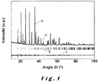
- the figure 1 is a graph representing an X-ray diffraction pattern ( ⁇ Cuk ⁇ ) of a 0.95 B 0.033 PO 4 / C LiFe powder containing 2.5% by weight of carbon according to the invention (A).
- the curves (D) and (C) respectively correspond to the simulated diagrams and to the difference between the experimental and simulated diagrams.
- the figure 2 is a graph showing the grain size distribution of a 0.95 B 0.033 PO 4 / C LiFe powder containing 2.5% by weight of carbon according to the invention.
- the particle size analysis was performed by laser diffraction.
- Curve (A) represents the volume fraction for each grain size interval considered.
- the curve (B) represents the cumulative volume fraction, and reads from left to right.
- the figure 3 illustrates a photo of a 0.95 B 0.033 PO 4 / C LiFe powder containing 2.5% by weight of carbon according to the invention obtained by scanning electron microscopy (SEM) in backscattered electron mode.
- SEM scanning electron microscopy
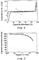
- the figure 4 is a graph showing a charge / discharge curve in galvanostatic mode (C / 5 regime, 20 ° C) of a 0.95 B 0.033 PO 4 / C LiFe powder containing 2.5% by weight of carbon according to US Pat. 'invention.
- the theoretical capacity of the LiFePO 4 / FePO 4 pair is 170 mAh / g.
- the carbon in the LiFePO 4 / C composite lowers this value by a few milliamperes hours per gram.
- the figure 5 represents the evolution of the specific capacity of a 0.95 B 0.033 PO 4 / C LiFe powder containing 2.5% by weight of carbon according to the invention as a function of the imposed discharge regime.
- the figure 6 represents the evolution of the specific capacity of a 0.985 B 0.010 PO 4 / C LiFe powder containing 2.5% by weight of carbon obtained according to Example 5 according to the invention as a function of the imposed discharge regime.
- the figure 7 represents the evolution of the specific capacity of a 0.985 B 0.010 PO 4 / C LiFe powder containing 2.5% by weight of carbon obtained according to another variant of the process according to the invention as a function of the imposed discharge regime.
- the present invention relates to a process for synthesizing an optimized LiFePO 4 / C composite enabling the elaboration of thick electrodes, then the manufacture of Li-ion accumulators with an energy density of greater than 140 Wh / kg (140-180 Wh / kg).
- the theoretical capacity of lithium iron phosphate LiFePO 4 is 170 mAh / g.
- the operating potential of the LiFePO 4 / FePO 4 system (3.45 V vs. Li + / Li) and the density (3.5 kg / L) are lower than for LiCoO 2 / Li 0.45 CoO 2 ( ⁇ 4.0 V vs. Li + / Li and 5.0 kg / L).
- iron phosphate has a very low intrinsic cost, a very long cycle life (ie the number of charge and discharge cycles without significant loss, knowing that 20% less capacity initial is often considered a significant loss of capacity value) and a safety component much higher than that of lamellar oxides, especially in the charged state (high thermal and chemical reactivity of Li x CoO 2 , 0 ⁇ x ⁇ 1) .
- the process for synthesizing the LiFePO 4 / C electrode composite material according to the present invention involves several successive steps, including a mechanochemical activation step that is particularly energy efficient. comparison of conventional grinding / mechanochemical activation steps.
- This synthesis route allows the preparation of LiFePO 4 / C composite suitable for the realization of thick electrodes and Li-ion cells of high density of mass energy (140 to 180 Wh / kg) by providing an electrode composite material having high density due to nanoscale fineness and micron aggregate formation after grinding.
- the first step of the synthesis is to prepare an iron (II) precursor according to the following reaction (or a similar reaction employing other reagents): 2NaOH + 2 (NH 4 ) 2 HPO 4 + 3FeSO 4 • 7H 2 O ⁇ Fe 3 (PO 4 ) 2 • 8H 2 O + 2 (NH 4 ) 2 SO 4 + Na 2 SO 4 + 15H 2 O
- This synthetic iron (II) phosphate of composition Fe 3 (PO 4 ) 2 • 8H 2 O is similar to the mineral vivianite. It is obtained by precipitation in aqueous solution according to a stoichiometric reaction between Fe 2+ ions and PO 4 3- species (embodiment 1).
- the second step of the synthesis involves grinding the iron precursor thus prepared, a lithium source, and optionally a source of boron and a carbon source, according to the following general reaction: ⁇ .Fe 3 (PO 4 ) 2 • 8H 2 O + 3. ⁇ .BPO 4 + Li 3 PO 4 + Cellulose ⁇ "homogeneous mixture of reagents" in which 0 ⁇ ⁇ / ⁇ ⁇ 0.1 and ⁇ + ⁇ ⁇ 1
- This second step consists of a mechanochemical activation of the various precursors, which will form after heat treatment the desired LiFePO 4 / carbon composite (Exemplary embodiment 2).
- the third step consists in carrying out a rapid heat treatment (of the order of 15 to 30 minutes) of the precursors under inert atmosphere (argon) to form the LiFePO 4 / C composite.
- the temperature is generally between 550 and 650 ° C.
- the overall reaction involved is as follows: Fe 3 (PO 4 ) 2 • 8H 2 O + Li 3 PO 4 + Cellulose ⁇ 3LiFePO 4 / C (-97/3 by weight) + water + aldehydes + other degradation products of cellulose
- LiFePO 4 electrodes can be made. Their development uses said powder, one or more electronic conductive additives (carbon fibers, carbon black, etc.) and an organic binder. The respective proportions are generally of the order of 80 to 92%, 4 to 14%, and 4 to 10% by weight.
- the basis weight (or capacitance) of the electrode varies, depending on the application, from 2 to 4 mAh / cm 2 , and its porosity is between 50 and 25%.
- Two liters of deionized water are placed under magnetic stirring in a beaker at room temperature.
- the oxygen of the water is removed by bubbling argon through a sinter. This bubbling is initiated at least 15 minutes before the introduction of the reagents, and is maintained throughout the synthesis.
- Bubbling and stirring are then stopped to allow the precipitate to settle at the bottom of the beaker.
- the liquid phase is removed.
- the precipitate is then washed with distilled water and centrifuged: the paste containing the precipitate is introduced into 100 ml glass tubes and centrifuged in order to separate the precipitate from the liquid phase (50-80 ml of deionized water and deoxygenated are previously introduced into each tube, then placed under stirring). The operation is repeated at least twice more.
- the precipitate is rinsed one last time with acetone.
- the precipitate is dried under dynamic vacuum (Büchi, .7): in a first step, the vacuum is carried out at ambient temperature for 1 h, then heated at 60 ° C for 16 h while maintaining the vacuum.
- the product obtained has the composition Fe 3 (PO 4 ) 2 , nH 2 O (n ⁇ 8). It is blue in color.
- the grinding is started, the rotational speed is +400 / -400 revolutions per minute in order to achieve energy grinding.
- the effective duration of the grinding is 1 h, carried out in 4 cycles of 15 min spaced by a pause of 5 min to limit the heating of the bowls, whose cooling by air is insufficient to grind without interruptions.
- the bowl is then introduced again in a glove box.
- the ground powder is recovered. Synthesis precursors are now activated (intimate nanostructured mixing).
- the powder can be stored under argon until it is heat treated.
- the mechanochemically activated powder by grinding is introduced into a gold nacelle, which is placed in a sealed quartz tube (440 ml internal volume - 30 mm outside diameter, length of 500 mm). Outside the glove box, the quartz tube is introduced for 15 min in an oven already preheated to 600 ° C. The tube is then removed from the oven ( ⁇ quenched in air). Thus, the powder reaches very quickly the synthesis temperature and remains there only for a short time. Once cooled, the powder is recovered under air and stored after reconditioning under argon. LiFe 0.95 B 0.033 PO 4 / C composite is formed.
- these aggregates consist of a compact micrometric assembly of nanoparticles.
- this system delivers a capacity of approximately 160 mAh / g and an average voltage of 3.4 V, as can be seen at Figures 4 and 5 ,.
- a Li-ion battery was constructed from a positive electrode containing the 0.95 B 0.033 PO 4 / C LiFe composite of the invention, a carbon negative electrode and a commercial polypropylene separator. and polyethylene imbibed with liquid electrolyte consisting of LiPF 6 (1 mol L -1) in solution in a mixture of propylene carbonate, dimethyl carbonate and ethylene carbonate.
- the positive electrode is composed of 90% by weight of LiFe 0.95 B 0.033 PO 4 / C, 4% by weight of carbon (carbon fibers and carbon black in identical proportions) and 6% by weight polyvinylidene hexafluoride as a binder.
- the mixture is carried out in solution of N-methylpyrrolidone.
- the ink formed is deposited on an aluminum current collector such that the surface capacity is 3.8 mAh / cm 2 . After evaporation of the solvent, the electrode is calendered to reach a porosity of 35%.
- this accumulator has a nominal energy of more than 160 Wh / kg.
- Example 5 Formation of said composite electrode material according to the invention according to an industrializable mechanosynthesis step
- the premixed powder is transferred confined and under argon to the grinding vessel of a Simoloyer® high energy mill, available from Zoz GmbH, using a sealed connection system.
- the tank is made of stainless steel, has an internal volume of 20 liters, is equipped with a stellite rotor and is partially filled with 25 kg of 100C6 steel balls with a diameter of 5 mm.
- the tank is maintained under static argon. If necessary after loading the powder, the tank is reinitiated (3 evacuated and returned under argon) so that the atmosphere inside is free of oxygen during grinding.
- the tank is cooled by a circulation of water of 12 liters per minute in the double envelope constituting its walls.
- the grinding is started, the speed of rotation of the rotor is 750 revolutions per minute in order to achieve energy grinding.
- the grinding time is 15 minutes.
- the discharge of the powder is carried out in a confined manner and under argon sweep, the outlet of the tank is connected to a recovery container of 3 liters.
- the rotational speed of the rotor is 750 rpm during unloading which lasts 15 minutes.
- Synthesis precursors are now activated (intimate nanostructured mixing).
- the powder can be stored under argon until it is heat treated.
- Example 3 A sample taken after 15 minutes of grinding (before unloading) and a sample taken at the end of unloading (ie 30 minutes of actual grinding) are heat-treated according to the calcination procedures of Example 2, put in lithium-metal accumulator and tested. according to the modalities of Example 3.
- the respective accumulators deliver a specific capacity of 157 mAh / g (for 15 minutes of grinding) and 155 mAh / g (for 15 minutes of grinding plus 15 minutes of unloading).
- Example 6 Formation of said composite electrode material according to the invention according to an industrializable mechanosynthesis step
- the tank is cooled continuously.
- the grinding is started, the rotational speed of the agitator is 230 rpm for the purpose of performing energy grinding.
- the grinding time is 2 hours.
- Synthesis precursors are now activated (intimate nanostructured mixing).
- the powder can be stored under argon until it is heat treated.
- a representative sample taken on the unloaded batch is heat-treated according to the calcination method of Example 2, put in lithium-metal accumulator and tested according to the modalities of Example 3.
- the battery delivers a specific capacity of 158 mAh / g.
- Example 3 was repeated several times with the exception that the type and duration of milling were changed for the precursor mixture.
- the data of the comparative examples were compared with those obtained with Examples 2, 5 and 6.
- Comparative Example 1 does not make it possible to obtain a production of boron / C-doped lithium iron phosphate industrially on the one hand because it was carried out in a planetary type grinder of laboratory with a maximum capacity of 250 ml.
- clogging occurred probably due to the nature of the precursors used which contain water.
- the planetary mill container has been manually unclogged several times (hourly), which, although not sufficient, presents an increased risk of possible contamination of the product.
- the energy transmitted by the beads to the precursors was probably not high enough.
- a surface capacity of 143 mAh / g for a thick electrode of the order of 4 mAh / cm 2 to C / 10 is not sufficient for operation according to the market needs of this compound obtained.
- Example 2 made it possible to obtain satisfactory thin and thick electrodes with a reduced grinding time to 1 hour in a planetary mill. This is particularly surprising in view of the grinding times disclosed in the prior documents, generally between 8 and 10 hours.
- the planetary mills of laboratories do not make it possible to produce the electrode material on an industrial scale, but this example constitutes a good reference for the desired characteristics of the product according to the invention.
- the balls were made of tungsten carbide, which made it possible to improve the grinding efficiency and to develop the sufficient mechanochemical energy to obtain a cathode material having the advantageous electro-chemical characteristics according to the invention and under form of mixed micrometric aggregates of nanoscale particles.
- Comparative Examples 2 and 3 were made on an attritor with a capacity of 2.5 liters with steel balls.
- the maximum relative speed of the beads was 1m / sec.
- a scraper was used to continuously unclog the contents of the attritor. Despite this permanent declogging, the energy conferred on the contained precursors was not sufficient to provide a satisfactory product for thin or thick electrode applications.
- the grinding time was extended to 10 hours to counteract the loss of energy imparted to the precursors being milled, without this being sufficient for the CFE surface capacity to be satisfactory. , even if the CSF value (surface capacitance in fine electrode) was satisfactory.
- Comparative Examples 4 and 5 were carried out on a Simoloyer® mill with a maximum relative bead speed of 3.75 m / sec. However, a significant clogging was observed and even a prolonged duration of the grinding time could not counteract the loss of the energy conferred on the precursors contained in the mill. In addition, for such energy-intensive mills, grinding times of 4 hours and still more than 16 hours are not acceptable for large-scale profitable production. These comparative examples are not industrializable, besides the electrochemical performances are not satisfactory, either in thick electrodes or in thin electrodes.
- Example 5 was carried out under the same conditions as Comparative Examples 4 and 5, with the exception that the grinding time was reduced to 15 minutes and that the relative speed peak of logs was 11.25 m / sec.
- the specific capacitance values at C / 10 for a fine electrode of the order of 0.4 mAh / cm 2 (mAh / g) and specific capacitance at C / 10 for thick electrode of the order of 4 mAh / cm 2 (mAh / g) were respectively 157 and 152 mAh / g, which is quite satisfactory for the market demand.
- the process is industrially feasible since the consumption of a grinding step of 15 minutes at 11.25 m / sec is low and this type of mill is large scale and can be used in a production process.
- Example 6 according to the invention was carried out under the same conditions as Comparative Examples 2 and 3 with the exception that the grinding time was reduced to 2 hours and the maximum relative speed of the balls was 2 85 m / sec, with continuous decolouring as in Comparative Examples 2 and 3.
- the specific capacitance values at C / 10 for a fine electrode of the order of 0.4 mAh / cm 2 (mAh / g) and specific capacitance at C / 10 for thick electrode of the order of 4 mAh / cm 2 (mAh / g) were respectively 158 and 153 mAh / g, which is quite satisfactory for the market demand and nonblisable.
Landscapes
- Chemical & Material Sciences (AREA)
- Chemical Kinetics & Catalysis (AREA)
- General Chemical & Material Sciences (AREA)
- Electrochemistry (AREA)
- Organic Chemistry (AREA)
- Inorganic Chemistry (AREA)
- Engineering & Computer Science (AREA)
- Composite Materials (AREA)
- Manufacturing & Machinery (AREA)
- Materials Engineering (AREA)
- Crystallography & Structural Chemistry (AREA)
- Battery Electrode And Active Subsutance (AREA)
- Secondary Cells (AREA)
Claims (23)
- Elektrodenmaterial mit der folgenden Formel LiαFeβBγPO4/C, wobei 0,85 ≤ α ≤ 1,08, 0 ≤ γ/β ≤ 0,1 und γ + β ≤ 1, dadurch gekennzeichnet, dass es in Form mikrometrischer, mikrogeschmiedeter Mischaggregate von nanometrischen Partikeln vorliegt, wobei die nanometrischen Partikel eine maximale Größe, gemessen durch Transmissionsmikroskopie, von weniger als 50 nm aufweisen und die mikrometrischen Mischaggregate eine durchschnittliche Größe (D50), gemessen durch Laser-Granulometrie in Methanol, von zwischen 0,5 und 60 µm aufweisen.
- Elektrodenmaterial nach Anspruch 1, wobei die mikrometrischen Mischaggregate eine durchschnittliche Größe (D50), gemessen durch Laser-Granulometrie in Methanol, von zwischen 1 und 45 µm aufweisen.
- Elektrodenmaterial nach Anspruch 1 oder Anspruch 2, wobei die mikrometrischen Mischaggregate eine durchschnittliche Größe (D50), gemessen durch Laser-Granulometrie in Methanol, von zwischen 2 und 15 µm aufweisen.
- Elektrodenmaterial nach irgendeinem der Ansprüche 1 bis 3, mit der folgenden Formel LiFeβBγPO4/C, wobei γ + β < 1.
- Elektrodenmaterial nach Anspruch 4 mit der Formel LiFe0,95B0,033PO4/C.
- Elektrodenmaterial nach irgendeinem der Ansprüche 1 bis 5, wobei der Gehalt an Restkohlenstoff strikt zwischen 1 und 3 Gew.-% im Verhältnis zum Gewicht des erwähnten Elektrodenmaterials liegt.
- Elektrodenmaterial nach irgendeinem der Ansprüche 1 bis 6, wobei die Klopfdichte zwischen 0,8 und 1,5 g/cm3 beträgt.
- Elektrodenmaterial nach Anspruch 7, wobei die Klopfdichte ungefähr 1,1 g/cm3 beträgt.
- Elektrodenmaterial nach irgendeinem der Ansprüche 1 bis 8, wobei die spezifische Oberfläche, gemessen nach dem BET-Verfahren, 12 bis 24 m2/g beträgt.
- Elektrodenmaterial nach dem Anspruch 9, wobei die spezifische Oberfläche, gemessen nach dem BET-Verfahren, 16 bis 22 m2/g beträgt.
- Elektrodenmaterial nach dem Anspruch 9 oder dem Anspruch 10, wobei die spezifische Oberfläche, gemessen nach dem BET-Verfahren, 18 bis 20 m2/g beträgt.
- Elektrodenmaterial nach irgendeinem der Ansprüche 1 bis 11, wobei die durchschnittliche Größe der Partikel D50, gemessen durch Laser-Granulometrie in Methanol, zwischen 3 und 8 µm liegt.
- Elektrode aus Verbundmaterial von Lithiumeisenphosphat und Kohlenstoff nach irgendeinem der Ansprüche 1 bis 12, die, bei einer Flächenkapazität von weniger als 2 mAh/cm2, eine spezifische praktische Elektrodenkapazität von zwischen 150 und 170 mAh/g aufweist, bevorzugt zwischen 155 und 170 mAh/g.
- Elektrode aus Verbundmaterial von Lithiumeisenphosphat und Kohlenstoff nach irgendeinem der Ansprüche 1 bis 12, die, bei einer Flächenkapazität von zwischen 2 und 4 mAh/cm2, eine spezifische praktische Kapazität von mehr als 150 mAh/g und weniger als 170 mAh/g aufweist.
- Elektrode nach Anspruch 13 oder Anspruch 14, welche ferner einen oder mehrere elektronische, leitende Zusätze und einen oder mehrere organische Bindemittel umfasst.
- Elektrode nach Anspruch 15, wobei der oder die mehreren elektronischen, leitenden Zusätze aus der Gruppe bestehend aus Kohlenstofffasern, Kohlenschwarz, Kohlenstoffnanorohren ausgewählt wird.
- Elektrode nach irgendeinem der Ansprüche 15 bis 16, wobei das Elektrodenmaterial in einer Menge von 80 bis 92 Gew.-% im Verhältnis zum Gesamtgewicht der Elektrode vorhanden ist.
- Elektrode nach irgendeinem der Ansprüche 15 bis 17, wobei der oder die mehreren elektronischen, leitenden Zusätze in einer Menge von 4 bis 14 Gew.-% im Verhältnis zum Gesamtgewicht der Elektrode vorhanden ist.
- Elektrode nach irgendeinem der Ansprüche 15 bis 18, wobei das oder die erwähnten mehreren organischen Bindemittel in einer Menge von 4 bis 10 Gew.-% im Verhältnis zum Gesamtgewicht der Elektrode vorhanden ist.
- Elektrode nach irgendeinem der Ansprüche 14 bis 20, mit einer Porosität von zwischen 50 und 25 %.
- Elektrochemische Li-Ionen-Zelle, welche eine Elektrode nach irgendeinem der Ansprüche 14 bis 20 umfasst.
- Elektrochemische Zelle nach Anspruch 21, welche ferner eine negative Kohlenstoffelektrode und ein leitendes Elektrolyt der Li+-Ionen umfasst.
- Elektrochemische Zelle nach Anspruch 21 oder Anspruch 22, welche eine Massenenergiedichte von zwischen 160 und 180 Wh/kg aufweist.
Applications Claiming Priority (3)
| Application Number | Priority Date | Filing Date | Title |
|---|---|---|---|
| EP10151986.6A EP2355214B1 (de) | 2010-01-28 | 2010-01-28 | Lithium-Akku auf Lithiumeisenphosphat und Kohlenstoffbasis |
| EP11701509.9A EP2529433B1 (de) | 2010-01-28 | 2011-01-28 | Verfahren zur Herstellung eines Verbundmaterials aus Lithiumeisenphosphat und Kohlenstoff |
| PCT/EP2011/051203 WO2011092283A1 (fr) | 2010-01-28 | 2011-01-28 | Accumulateurs au lithium a base de phosphate de fer lithie et de carbone |
Related Parent Applications (2)
| Application Number | Title | Priority Date | Filing Date |
|---|---|---|---|
| EP11701509.9A Division EP2529433B1 (de) | 2010-01-28 | 2011-01-28 | Verfahren zur Herstellung eines Verbundmaterials aus Lithiumeisenphosphat und Kohlenstoff |
| EP11701509.9A Division-Into EP2529433B1 (de) | 2010-01-28 | 2011-01-28 | Verfahren zur Herstellung eines Verbundmaterials aus Lithiumeisenphosphat und Kohlenstoff |
Publications (2)
| Publication Number | Publication Date |
|---|---|
| EP2840633A1 EP2840633A1 (de) | 2015-02-25 |
| EP2840633B1 true EP2840633B1 (de) | 2018-10-17 |
Family
ID=42288747
Family Applications (3)
| Application Number | Title | Priority Date | Filing Date |
|---|---|---|---|
| EP10151986.6A Not-in-force EP2355214B1 (de) | 2010-01-28 | 2010-01-28 | Lithium-Akku auf Lithiumeisenphosphat und Kohlenstoffbasis |
| EP14184728.5A Not-in-force EP2840633B1 (de) | 2010-01-28 | 2011-01-28 | Lithium-Akku auf Lithiumeisenphosphat und Kohlenstoffbasis |
| EP11701509.9A Active EP2529433B1 (de) | 2010-01-28 | 2011-01-28 | Verfahren zur Herstellung eines Verbundmaterials aus Lithiumeisenphosphat und Kohlenstoff |
Family Applications Before (1)
| Application Number | Title | Priority Date | Filing Date |
|---|---|---|---|
| EP10151986.6A Not-in-force EP2355214B1 (de) | 2010-01-28 | 2010-01-28 | Lithium-Akku auf Lithiumeisenphosphat und Kohlenstoffbasis |
Family Applications After (1)
| Application Number | Title | Priority Date | Filing Date |
|---|---|---|---|
| EP11701509.9A Active EP2529433B1 (de) | 2010-01-28 | 2011-01-28 | Verfahren zur Herstellung eines Verbundmaterials aus Lithiumeisenphosphat und Kohlenstoff |
Country Status (10)
| Country | Link |
|---|---|
| US (3) | US8703332B2 (de) |
| EP (3) | EP2355214B1 (de) |
| JP (1) | JP5649662B2 (de) |
| KR (1) | KR101758244B1 (de) |
| CN (1) | CN102725887B (de) |
| ES (1) | ES2671318T3 (de) |
| HK (1) | HK1206488A1 (de) |
| RU (1) | RU2551849C2 (de) |
| TW (1) | TWI543430B (de) |
| WO (1) | WO2011092283A1 (de) |
Families Citing this family (27)
| Publication number | Priority date | Publication date | Assignee | Title |
|---|---|---|---|---|
| EP2355214B1 (de) * | 2010-01-28 | 2013-12-25 | Prayon | Lithium-Akku auf Lithiumeisenphosphat und Kohlenstoffbasis |
| CN102306791B (zh) * | 2011-08-18 | 2014-08-06 | 合肥国轩高科动力能源股份公司 | 一种碳包覆非化学计量比氧化锂铁磷材料的制备方法 |
| FR2983190B1 (fr) * | 2011-11-28 | 2014-04-11 | Renault Sa | Obtention d'un materiau a base de li4ti5o12 avec broyage en presence de carbone |
| DE102011056816A1 (de) * | 2011-12-21 | 2013-08-01 | Chemische Fabrik Budenheim Kg | Mangan enthaltende Metallphosphate und Verfahren zu deren Herstellung |
| DE102011056812A1 (de) | 2011-12-21 | 2013-06-27 | Chemische Fabrik Budenheim Kg | Metallphosphate und Verfahren zu deren Herstellung |
| FR2985857B1 (fr) | 2012-01-17 | 2014-01-03 | Hutchinson | Cathode pour cellule de batterie lithium-ion, son procede de fabrication et cette batterie l'incorporant. |
| CN102931409B (zh) * | 2012-10-25 | 2015-08-12 | 中国计量学院 | 一种核壳结构的锂离子电池负极用聚苯胺/硅复合材料制备方法 |
| US9755222B2 (en) | 2013-03-15 | 2017-09-05 | Johnson Matthey Public Limited Company | Alkali metal oxyanion electrode material having a carbon deposited by pyrolysis and process for making same |
| CN105122508B (zh) * | 2013-04-26 | 2018-04-06 | 夏普株式会社 | 锂离子二次电池用正极以及包括该正极的锂离子二次电池 |
| JP6137088B2 (ja) * | 2014-08-29 | 2017-05-31 | トヨタ自動車株式会社 | リチウムイオン電池用正極活物質層の製造方法、及びリチウムイオン電池用正極活物質層 |
| KR101682381B1 (ko) * | 2015-03-16 | 2016-12-05 | 한국교통대학교 산학협력단 | 탄소 코팅 리튬인산철의 제조방법 |
| US10174753B2 (en) * | 2015-11-04 | 2019-01-08 | Haier Us Appliance Solutions, Inc. | Method for operating a linear compressor |
| CN105390693B (zh) * | 2015-11-13 | 2018-01-02 | 山东精工电子科技有限公司 | 一种高容量纳米晶正极材料LiNi0.8Co0.1Mn0.1O2及其高压合成方法 |
| CN108306019B (zh) * | 2018-01-29 | 2020-03-27 | 蒋央芳 | 一种碳掺杂磷酸铁锂的制备方法 |
| CN108598398B (zh) * | 2018-04-09 | 2020-12-08 | 中科锂电新能源有限公司 | 一种碳化硼与碳共包覆的复合正极材料、其制备方法和锂离子电池 |
| AU2019310592B2 (en) | 2018-07-27 | 2024-12-19 | Form Energy, Inc. | Negative electrodes for electrochemical cells |
| CN109336079A (zh) * | 2018-11-20 | 2019-02-15 | 浙江瑞邦科技有限公司 | 一种高压实磷酸铁锂材料的制备方法 |
| CN109841809A (zh) * | 2019-01-04 | 2019-06-04 | 三峡大学 | 一种Na3V2(PO4)3/C多孔微球钠离子电池正极材料的制备方法 |
| US12294086B2 (en) | 2019-07-26 | 2025-05-06 | Form Energy, Inc. | Low cost metal electrodes |
| CN121651451A (zh) | 2019-08-29 | 2026-03-13 | 诺沃尼克斯电池技术解决方案公司 | 改进的微造粒方法及其制得的产品粒子 |
| CN112575203B (zh) * | 2020-12-07 | 2022-11-04 | 金川集团股份有限公司 | 一种回收废旧动力锂电池中锂的方法 |
| CN113104829B (zh) * | 2021-03-19 | 2024-02-09 | 合肥国轩电池材料有限公司 | 一种磷酸铁锂材料及其制备方法和应用 |
| CN113929070B (zh) * | 2021-10-09 | 2022-05-17 | 湖北万润新能源科技股份有限公司 | 一种高倍率磷酸铁锂正极材料的制备方法 |
| CN115124013B (zh) * | 2022-08-05 | 2023-08-29 | 衢州华友钴新材料有限公司 | 一种电池级正磷酸铁的制备方法 |
| TWI827275B (zh) * | 2022-09-27 | 2023-12-21 | 台灣立凱電能科技股份有限公司 | 磷酸鋰鐵正極材料的製備方法 |
| CN116805685B (zh) * | 2023-08-22 | 2024-01-23 | 深圳海辰储能控制技术有限公司 | 正极活性材料、正极极片、锂离子电池及用电设备 |
| CN118343721A (zh) * | 2024-04-15 | 2024-07-16 | 格林美(无锡)能源材料有限公司 | 一种磷酸铁锂正极材料及其制备方法和应用 |
Family Cites Families (30)
| Publication number | Priority date | Publication date | Assignee | Title |
|---|---|---|---|---|
| DE4307083B4 (de) | 1993-03-06 | 2007-07-12 | Zoz Maschinenbau Gmbh | Vorrichtung zur Feinstmahlung von Feststoffen |
| JP4734700B2 (ja) * | 2000-09-29 | 2011-07-27 | ソニー株式会社 | 正極活物質の製造方法及び非水電解質電池の製造方法 |
| JP3921931B2 (ja) * | 2000-09-29 | 2007-05-30 | ソニー株式会社 | 正極活物質及び非水電解質電池 |
| TW513822B (en) | 2000-10-06 | 2002-12-11 | Sony Corp | Method for producing cathode active material and method for producing non-aqueous electrolyte cell |
| US6645452B1 (en) * | 2000-11-28 | 2003-11-11 | Valence Technology, Inc. | Methods of making lithium metal cathode active materials |
| EP1261050A1 (de) * | 2001-05-23 | 2002-11-27 | n.v. Umicore s.a. | Lithium-Übergangsmetall-Phosphatpulver für wiederaufladbaren Batterien |
| FR2848205B1 (fr) * | 2002-12-05 | 2006-03-24 | Commissariat Energie Atomique | Composes d'insertion du lithium substitues au bore, materiaux actifs d'electrodes, accumulateurs et dispositifs electrochromes |
| JP2004335344A (ja) * | 2003-05-09 | 2004-11-25 | Sanyo Electric Co Ltd | リチウム二次電池用正極及びリチウム二次電池 |
| CA2790806C (en) * | 2003-12-23 | 2013-04-02 | Universite De Montreal | Process for preparing electroactive insertion compounds and electrode materials obtained therefrom |
| US8617745B2 (en) * | 2004-02-06 | 2013-12-31 | A123 Systems Llc | Lithium secondary cell with high charge and discharge rate capability and low impedance growth |
| JP2007230784A (ja) * | 2004-03-30 | 2007-09-13 | Agc Seimi Chemical Co Ltd | リチウム鉄複合酸化物の製造方法 |
| US20070160519A1 (en) * | 2005-03-28 | 2007-07-12 | Jeremy Barker | Method Of Making Active Materials For Use In Secondary Electrochemical Cells |
| US7939201B2 (en) * | 2005-08-08 | 2011-05-10 | A123 Systems, Inc. | Nanoscale ion storage materials including co-existing phases or solid solutions |
| KR20130102647A (ko) * | 2005-09-09 | 2013-09-17 | 에이일이삼 시스템즈 인코포레이티드 | 고속 충전 및 방전 능력과 낮은 임피던스 증가를 나타내는 리튬 2차 전지 |
| TWI270994B (en) * | 2005-12-29 | 2007-01-11 | Ind Tech Res Inst | High rate capability design of lithium ion secondary battery |
| KR101334050B1 (ko) * | 2006-02-14 | 2013-12-05 | 토요타 찌도샤 카부시끼카이샤 | 리튬 이차 전지용 리튬 망간 인산염 포지티브 재료 |
| KR101331457B1 (ko) * | 2006-04-06 | 2013-11-21 | 토요타 찌도샤 카부시끼카이샤 | 리튬 이차 전지용 리튬 금속 인산염 양극 물질의 나노입자의 합성 |
| JP2007317534A (ja) * | 2006-05-26 | 2007-12-06 | Sony Corp | 非水電解質二次電池 |
| CA2559657A1 (en) * | 2006-09-13 | 2008-03-13 | Valence Technology, Inc. | Method of processing active materials for use in secondary electrochemical cells |
| US20090061314A1 (en) * | 2007-08-30 | 2009-03-05 | Ming Dong | Method of Processing Active Materials For Use In Secondary Electrochemical Cells |
| CA2569991A1 (en) * | 2006-12-07 | 2008-06-07 | Michel Gauthier | C-treated nanoparticles and agglomerate and composite thereof as transition metal polyanion cathode materials and process for making |
| US8168329B2 (en) * | 2007-06-18 | 2012-05-01 | Advanced Lithium Electrochemistry Co., Ltd. | Electrochemical composition and associated technology |
| US9105943B2 (en) * | 2007-09-12 | 2015-08-11 | Lg Chem, Ltd. | Non-aqueous electrolyte lithium secondary battery |
| JP5314264B2 (ja) * | 2007-09-26 | 2013-10-16 | 古河電池株式会社 | リチウム二次電池用正極活物質の製造法、正極活物質及びリチウム二次電池 |
| JP2009146773A (ja) * | 2007-12-14 | 2009-07-02 | Agc Seimi Chemical Co Ltd | オリビン型リチウム鉄リン複合酸化物およびその製造方法 |
| TWI369019B (en) * | 2007-12-27 | 2012-07-21 | Ind Tech Res Inst | Cathodal materials for lithium cells, methods for fabricating the same, and lithium secondary cells using the same |
| JP5291179B2 (ja) * | 2008-03-28 | 2013-09-18 | ビーワイディー カンパニー リミテッド | リチウム二次電池用のリン酸鉄リチウム正極材料を調製する方法 |
| EP2276698A1 (de) * | 2008-04-14 | 2011-01-26 | Dow Global Technologies Inc. | Lithiummetallphosphat/kohlenstoff-nanoverbundwerkstoffe als kathodenaktivmassen für lithium-sekundärbatterien |
| CN102422467B (zh) * | 2009-05-04 | 2014-09-10 | 觅科科技公司 | 电极活性复合材料及其制备方法 |
| EP2355214B1 (de) * | 2010-01-28 | 2013-12-25 | Prayon | Lithium-Akku auf Lithiumeisenphosphat und Kohlenstoffbasis |
-
2010
- 2010-01-28 EP EP10151986.6A patent/EP2355214B1/de not_active Not-in-force
-
2011
- 2011-01-28 CN CN201180007320.4A patent/CN102725887B/zh not_active Expired - Fee Related
- 2011-01-28 EP EP14184728.5A patent/EP2840633B1/de not_active Not-in-force
- 2011-01-28 JP JP2012550459A patent/JP5649662B2/ja not_active Expired - Fee Related
- 2011-01-28 TW TW100103366A patent/TWI543430B/zh not_active IP Right Cessation
- 2011-01-28 RU RU2012136180/04A patent/RU2551849C2/ru not_active IP Right Cessation
- 2011-01-28 ES ES11701509.9T patent/ES2671318T3/es active Active
- 2011-01-28 WO PCT/EP2011/051203 patent/WO2011092283A1/fr not_active Ceased
- 2011-01-28 US US13/574,754 patent/US8703332B2/en not_active Expired - Fee Related
- 2011-01-28 EP EP11701509.9A patent/EP2529433B1/de active Active
- 2011-01-28 KR KR1020127022428A patent/KR101758244B1/ko not_active Expired - Fee Related
-
2013
- 2013-12-23 US US14/139,475 patent/US9287558B2/en not_active Expired - Fee Related
-
2015
- 2015-07-23 HK HK15107060.3A patent/HK1206488A1/xx unknown
- 2015-11-18 US US14/945,278 patent/US20160072122A1/en not_active Abandoned
Non-Patent Citations (1)
| Title |
|---|
| None * |
Also Published As
| Publication number | Publication date |
|---|---|
| JP5649662B2 (ja) | 2015-01-07 |
| EP2529433A1 (de) | 2012-12-05 |
| US20130040198A1 (en) | 2013-02-14 |
| RU2012136180A (ru) | 2014-03-10 |
| US20140186705A1 (en) | 2014-07-03 |
| KR20120137357A (ko) | 2012-12-20 |
| KR101758244B1 (ko) | 2017-07-14 |
| EP2529433B1 (de) | 2018-03-07 |
| US8703332B2 (en) | 2014-04-22 |
| EP2355214A1 (de) | 2011-08-10 |
| CN102725887A (zh) | 2012-10-10 |
| CN102725887B (zh) | 2016-02-17 |
| US20160072122A1 (en) | 2016-03-10 |
| JP2013518379A (ja) | 2013-05-20 |
| RU2551849C2 (ru) | 2015-05-27 |
| US9287558B2 (en) | 2016-03-15 |
| TWI543430B (zh) | 2016-07-21 |
| EP2840633A1 (de) | 2015-02-25 |
| WO2011092283A1 (fr) | 2011-08-04 |
| EP2355214B1 (de) | 2013-12-25 |
| ES2671318T3 (es) | 2018-06-06 |
| HK1206488A1 (en) | 2016-01-08 |
| TW201138193A (en) | 2011-11-01 |
Similar Documents
| Publication | Publication Date | Title |
|---|---|---|
| EP2529433B1 (de) | Verfahren zur Herstellung eines Verbundmaterials aus Lithiumeisenphosphat und Kohlenstoff | |
| EP1325525B1 (de) | Syntheseverfahren von redoxmaterialien mit kohlenstoffhaltiger umhüllung und kontrollierter teilchengrösse | |
| EP1339642B1 (de) | Verfahren zur herstellung von li4ti5o12, li(4-a)zati5o12, or li4zbti(5-b)o12 teilchen | |
| CN104937756B (zh) | 正极活性物质-石墨烯复合物颗粒和锂离子电池用正极材料 | |
| EP2134650B1 (de) | Synthese einer limpo4-verbindung | |
| JP2021517721A (ja) | 充電式リチウムイオン電池用の正極材料を調製する方法 | |
| JP2020031028A (ja) | リチウムイオン二次電池用混合正極活物質及びその製造方法 | |
| WO2015041063A1 (ja) | ケイ素相含有物黒鉛複合粒子およびその製造方法 | |
| EP2152630A1 (de) | Verfahren zur herstellung von polyanionischen lithiumübergangsmetallpulvern für batterien | |
| JP2014051418A (ja) | 複合材料及びその製造方法、正極活物質、正極、並びに非水電解質二次電池 | |
| EP2757068B1 (de) | Syntheseverfahren einer LiM1-x-y-zNyQzFexPO4-Verbindung, und ihre Verwendung als Elektrodenmaterial für einen Lithium-Akkumulator | |
| JP2020043009A (ja) | 混合正極活物質用オリビン型リチウム系酸化物一次粒子及びその製造方法 | |
| CN111566847A (zh) | 用于可充电锂电池的硅微反应器 | |
| KR101942654B1 (ko) | 금속/카본 결정 입자 복합체, 이의 제조방법 및 이를 함유하는 에너지 저장소자 | |
| TW201508982A (zh) | 聚陰離子系正極活性物質複合體粒子的製造方法及聚陰離子系正極活性物質的前驅物-氧化石墨複合造粒體 | |
| KR20210047874A (ko) | 복합체 애노드를 구비한 재충전 가능한 리튬 배터리 | |
| JP2025536429A (ja) | 遊離粒子及び電気化学セルにおける使用のための作製方法 | |
| JP7429001B2 (ja) | リチウムイオン二次電池用正極及びリチウムイオン二次電池 | |
| EP4594253A1 (de) | Verfahren zur synthese eines materials für eine lithium-ionen-batterie aus nanoporösen lithiumeisenphosphatpartikeln | |
| EP3571162A1 (de) | Verfahren zur herstellung von nichtagglomerierten nanopartikeln auf einem lithiumlamellenoxid | |
| WO2025023816A1 (fr) | Procede de preparation de lithium fer phosphate micrometrique |
Legal Events
| Date | Code | Title | Description |
|---|---|---|---|
| PUAI | Public reference made under article 153(3) epc to a published international application that has entered the european phase |
Free format text: ORIGINAL CODE: 0009012 |
|
| 17P | Request for examination filed |
Effective date: 20140915 |
|
| AC | Divisional application: reference to earlier application |
Ref document number: 2529433 Country of ref document: EP Kind code of ref document: P |
|
| AK | Designated contracting states |
Kind code of ref document: A1 Designated state(s): AL AT BE BG CH CY CZ DE DK EE ES FI FR GB GR HR HU IE IS IT LI LT LU LV MC MK MT NL NO PL PT RO RS SE SI SK SM TR |
|
| AX | Request for extension of the european patent |
Extension state: BA ME |
|
| R17P | Request for examination filed (corrected) |
Effective date: 20150706 |
|
| RBV | Designated contracting states (corrected) |
Designated state(s): AL AT BE BG CH CY CZ DE DK EE ES FI FR GB GR HR HU IE IS IT LI LT LU LV MC MK MT NL NO PL PT RO RS SE SI SK SM TR |
|
| REG | Reference to a national code |
Ref country code: HK Ref legal event code: DE Ref document number: 1206488 Country of ref document: HK |
|
| GRAP | Despatch of communication of intention to grant a patent |
Free format text: ORIGINAL CODE: EPIDOSNIGR1 |
|
| STAA | Information on the status of an ep patent application or granted ep patent |
Free format text: STATUS: GRANT OF PATENT IS INTENDED |
|
| INTG | Intention to grant announced |
Effective date: 20180508 |
|
| GRAS | Grant fee paid |
Free format text: ORIGINAL CODE: EPIDOSNIGR3 |
|
| GRAA | (expected) grant |
Free format text: ORIGINAL CODE: 0009210 |
|
| STAA | Information on the status of an ep patent application or granted ep patent |
Free format text: STATUS: THE PATENT HAS BEEN GRANTED |
|
| AC | Divisional application: reference to earlier application |
Ref document number: 2529433 Country of ref document: EP Kind code of ref document: P |
|
| AK | Designated contracting states |
Kind code of ref document: B1 Designated state(s): AL AT BE BG CH CY CZ DE DK EE ES FI FR GB GR HR HU IE IS IT LI LT LU LV MC MK MT NL NO PL PT RO RS SE SI SK SM TR |
|
| REG | Reference to a national code |
Ref country code: GB Ref legal event code: FG4D Free format text: NOT ENGLISH |
|
| REG | Reference to a national code |
Ref country code: CH Ref legal event code: EP |
|
| REG | Reference to a national code |
Ref country code: IE Ref legal event code: FG4D Free format text: LANGUAGE OF EP DOCUMENT: FRENCH |
|
| REG | Reference to a national code |
Ref country code: DE Ref legal event code: R096 Ref document number: 602011053111 Country of ref document: DE Ref country code: AT Ref legal event code: REF Ref document number: 1055037 Country of ref document: AT Kind code of ref document: T Effective date: 20181115 |
|
| REG | Reference to a national code |
Ref country code: NL Ref legal event code: MP Effective date: 20181017 |
|
| REG | Reference to a national code |
Ref country code: LT Ref legal event code: MG4D |
|
| REG | Reference to a national code |
Ref country code: AT Ref legal event code: MK05 Ref document number: 1055037 Country of ref document: AT Kind code of ref document: T Effective date: 20181017 |
|
| PG25 | Lapsed in a contracting state [announced via postgrant information from national office to epo] |
Ref country code: NL Free format text: LAPSE BECAUSE OF FAILURE TO SUBMIT A TRANSLATION OF THE DESCRIPTION OR TO PAY THE FEE WITHIN THE PRESCRIBED TIME-LIMIT Effective date: 20181017 |
|
| PG25 | Lapsed in a contracting state [announced via postgrant information from national office to epo] |
Ref country code: LV Free format text: LAPSE BECAUSE OF FAILURE TO SUBMIT A TRANSLATION OF THE DESCRIPTION OR TO PAY THE FEE WITHIN THE PRESCRIBED TIME-LIMIT Effective date: 20181017 Ref country code: AT Free format text: LAPSE BECAUSE OF FAILURE TO SUBMIT A TRANSLATION OF THE DESCRIPTION OR TO PAY THE FEE WITHIN THE PRESCRIBED TIME-LIMIT Effective date: 20181017 Ref country code: NO Free format text: LAPSE BECAUSE OF FAILURE TO SUBMIT A TRANSLATION OF THE DESCRIPTION OR TO PAY THE FEE WITHIN THE PRESCRIBED TIME-LIMIT Effective date: 20190117 Ref country code: BG Free format text: LAPSE BECAUSE OF FAILURE TO SUBMIT A TRANSLATION OF THE DESCRIPTION OR TO PAY THE FEE WITHIN THE PRESCRIBED TIME-LIMIT Effective date: 20190117 Ref country code: PL Free format text: LAPSE BECAUSE OF FAILURE TO SUBMIT A TRANSLATION OF THE DESCRIPTION OR TO PAY THE FEE WITHIN THE PRESCRIBED TIME-LIMIT Effective date: 20181017 Ref country code: HR Free format text: LAPSE BECAUSE OF FAILURE TO SUBMIT A TRANSLATION OF THE DESCRIPTION OR TO PAY THE FEE WITHIN THE PRESCRIBED TIME-LIMIT Effective date: 20181017 Ref country code: ES Free format text: LAPSE BECAUSE OF FAILURE TO SUBMIT A TRANSLATION OF THE DESCRIPTION OR TO PAY THE FEE WITHIN THE PRESCRIBED TIME-LIMIT Effective date: 20181017 Ref country code: LT Free format text: LAPSE BECAUSE OF FAILURE TO SUBMIT A TRANSLATION OF THE DESCRIPTION OR TO PAY THE FEE WITHIN THE PRESCRIBED TIME-LIMIT Effective date: 20181017 Ref country code: IS Free format text: LAPSE BECAUSE OF FAILURE TO SUBMIT A TRANSLATION OF THE DESCRIPTION OR TO PAY THE FEE WITHIN THE PRESCRIBED TIME-LIMIT Effective date: 20190217 Ref country code: FI Free format text: LAPSE BECAUSE OF FAILURE TO SUBMIT A TRANSLATION OF THE DESCRIPTION OR TO PAY THE FEE WITHIN THE PRESCRIBED TIME-LIMIT Effective date: 20181017 |
|
| PG25 | Lapsed in a contracting state [announced via postgrant information from national office to epo] |
Ref country code: GR Free format text: LAPSE BECAUSE OF FAILURE TO SUBMIT A TRANSLATION OF THE DESCRIPTION OR TO PAY THE FEE WITHIN THE PRESCRIBED TIME-LIMIT Effective date: 20190118 Ref country code: SE Free format text: LAPSE BECAUSE OF FAILURE TO SUBMIT A TRANSLATION OF THE DESCRIPTION OR TO PAY THE FEE WITHIN THE PRESCRIBED TIME-LIMIT Effective date: 20181017 Ref country code: RS Free format text: LAPSE BECAUSE OF FAILURE TO SUBMIT A TRANSLATION OF THE DESCRIPTION OR TO PAY THE FEE WITHIN THE PRESCRIBED TIME-LIMIT Effective date: 20181017 Ref country code: PT Free format text: LAPSE BECAUSE OF FAILURE TO SUBMIT A TRANSLATION OF THE DESCRIPTION OR TO PAY THE FEE WITHIN THE PRESCRIBED TIME-LIMIT Effective date: 20190217 Ref country code: AL Free format text: LAPSE BECAUSE OF FAILURE TO SUBMIT A TRANSLATION OF THE DESCRIPTION OR TO PAY THE FEE WITHIN THE PRESCRIBED TIME-LIMIT Effective date: 20181017 |
|
| REG | Reference to a national code |
Ref country code: DE Ref legal event code: R097 Ref document number: 602011053111 Country of ref document: DE |
|
| PG25 | Lapsed in a contracting state [announced via postgrant information from national office to epo] |
Ref country code: DK Free format text: LAPSE BECAUSE OF FAILURE TO SUBMIT A TRANSLATION OF THE DESCRIPTION OR TO PAY THE FEE WITHIN THE PRESCRIBED TIME-LIMIT Effective date: 20181017 Ref country code: IT Free format text: LAPSE BECAUSE OF FAILURE TO SUBMIT A TRANSLATION OF THE DESCRIPTION OR TO PAY THE FEE WITHIN THE PRESCRIBED TIME-LIMIT Effective date: 20181017 Ref country code: CZ Free format text: LAPSE BECAUSE OF FAILURE TO SUBMIT A TRANSLATION OF THE DESCRIPTION OR TO PAY THE FEE WITHIN THE PRESCRIBED TIME-LIMIT Effective date: 20181017 |
|
| REG | Reference to a national code |
Ref country code: DE Ref legal event code: R119 Ref document number: 602011053111 Country of ref document: DE |
|
| PLBE | No opposition filed within time limit |
Free format text: ORIGINAL CODE: 0009261 |
|
| STAA | Information on the status of an ep patent application or granted ep patent |
Free format text: STATUS: NO OPPOSITION FILED WITHIN TIME LIMIT |
|
| PG25 | Lapsed in a contracting state [announced via postgrant information from national office to epo] |
Ref country code: RO Free format text: LAPSE BECAUSE OF FAILURE TO SUBMIT A TRANSLATION OF THE DESCRIPTION OR TO PAY THE FEE WITHIN THE PRESCRIBED TIME-LIMIT Effective date: 20181017 Ref country code: SK Free format text: LAPSE BECAUSE OF FAILURE TO SUBMIT A TRANSLATION OF THE DESCRIPTION OR TO PAY THE FEE WITHIN THE PRESCRIBED TIME-LIMIT Effective date: 20181017 Ref country code: MC Free format text: LAPSE BECAUSE OF FAILURE TO SUBMIT A TRANSLATION OF THE DESCRIPTION OR TO PAY THE FEE WITHIN THE PRESCRIBED TIME-LIMIT Effective date: 20181017 Ref country code: EE Free format text: LAPSE BECAUSE OF FAILURE TO SUBMIT A TRANSLATION OF THE DESCRIPTION OR TO PAY THE FEE WITHIN THE PRESCRIBED TIME-LIMIT Effective date: 20181017 Ref country code: SM Free format text: LAPSE BECAUSE OF FAILURE TO SUBMIT A TRANSLATION OF THE DESCRIPTION OR TO PAY THE FEE WITHIN THE PRESCRIBED TIME-LIMIT Effective date: 20181017 |
|
| REG | Reference to a national code |
Ref country code: CH Ref legal event code: PL |
|
| 26N | No opposition filed |
Effective date: 20190718 |
|
| GBPC | Gb: european patent ceased through non-payment of renewal fee |
Effective date: 20190128 |
|
| PG25 | Lapsed in a contracting state [announced via postgrant information from national office to epo] |
Ref country code: LU Free format text: LAPSE BECAUSE OF NON-PAYMENT OF DUE FEES Effective date: 20190128 |
|
| REG | Reference to a national code |
Ref country code: IE Ref legal event code: MM4A |
|
| PG25 | Lapsed in a contracting state [announced via postgrant information from national office to epo] |
Ref country code: SI Free format text: LAPSE BECAUSE OF FAILURE TO SUBMIT A TRANSLATION OF THE DESCRIPTION OR TO PAY THE FEE WITHIN THE PRESCRIBED TIME-LIMIT Effective date: 20181017 Ref country code: DE Free format text: LAPSE BECAUSE OF NON-PAYMENT OF DUE FEES Effective date: 20190801 |
|
| PG25 | Lapsed in a contracting state [announced via postgrant information from national office to epo] |
Ref country code: CH Free format text: LAPSE BECAUSE OF NON-PAYMENT OF DUE FEES Effective date: 20190131 Ref country code: GB Free format text: LAPSE BECAUSE OF NON-PAYMENT OF DUE FEES Effective date: 20190128 Ref country code: LI Free format text: LAPSE BECAUSE OF NON-PAYMENT OF DUE FEES Effective date: 20190131 |
|
| PG25 | Lapsed in a contracting state [announced via postgrant information from national office to epo] |
Ref country code: IE Free format text: LAPSE BECAUSE OF NON-PAYMENT OF DUE FEES Effective date: 20190128 |
|
| PG25 | Lapsed in a contracting state [announced via postgrant information from national office to epo] |
Ref country code: TR Free format text: LAPSE BECAUSE OF FAILURE TO SUBMIT A TRANSLATION OF THE DESCRIPTION OR TO PAY THE FEE WITHIN THE PRESCRIBED TIME-LIMIT Effective date: 20181017 |
|
| PG25 | Lapsed in a contracting state [announced via postgrant information from national office to epo] |
Ref country code: MT Free format text: LAPSE BECAUSE OF FAILURE TO SUBMIT A TRANSLATION OF THE DESCRIPTION OR TO PAY THE FEE WITHIN THE PRESCRIBED TIME-LIMIT Effective date: 20181017 |
|
| PGFP | Annual fee paid to national office [announced via postgrant information from national office to epo] |
Ref country code: FR Payment date: 20201215 Year of fee payment: 11 |
|
| PGFP | Annual fee paid to national office [announced via postgrant information from national office to epo] |
Ref country code: BE Payment date: 20201215 Year of fee payment: 11 |
|
| PG25 | Lapsed in a contracting state [announced via postgrant information from national office to epo] |
Ref country code: CY Free format text: LAPSE BECAUSE OF FAILURE TO SUBMIT A TRANSLATION OF THE DESCRIPTION OR TO PAY THE FEE WITHIN THE PRESCRIBED TIME-LIMIT Effective date: 20181017 |
|
| PG25 | Lapsed in a contracting state [announced via postgrant information from national office to epo] |
Ref country code: HU Free format text: LAPSE BECAUSE OF FAILURE TO SUBMIT A TRANSLATION OF THE DESCRIPTION OR TO PAY THE FEE WITHIN THE PRESCRIBED TIME-LIMIT; INVALID AB INITIO Effective date: 20110128 |
|
| REG | Reference to a national code |
Ref country code: HK Ref legal event code: WD Ref document number: 1206488 Country of ref document: HK |
|
| PG25 | Lapsed in a contracting state [announced via postgrant information from national office to epo] |
Ref country code: MK Free format text: LAPSE BECAUSE OF FAILURE TO SUBMIT A TRANSLATION OF THE DESCRIPTION OR TO PAY THE FEE WITHIN THE PRESCRIBED TIME-LIMIT Effective date: 20181017 |
|
| REG | Reference to a national code |
Ref country code: BE Ref legal event code: MM Effective date: 20220131 |
|
| PG25 | Lapsed in a contracting state [announced via postgrant information from national office to epo] |
Ref country code: FR Free format text: LAPSE BECAUSE OF NON-PAYMENT OF DUE FEES Effective date: 20220131 Ref country code: BE Free format text: LAPSE BECAUSE OF NON-PAYMENT OF DUE FEES Effective date: 20220131 |