EP2833992B1 - Horizontalrührwerk - Google Patents
Horizontalrührwerk Download PDFInfo
- Publication number
- EP2833992B1 EP2833992B1 EP13711875.8A EP13711875A EP2833992B1 EP 2833992 B1 EP2833992 B1 EP 2833992B1 EP 13711875 A EP13711875 A EP 13711875A EP 2833992 B1 EP2833992 B1 EP 2833992B1
- Authority
- EP
- European Patent Office
- Prior art keywords
- cable
- assembly unit
- horizontal agitator
- coupling
- agitator according
- Prior art date
- Legal status (The legal status is an assumption and is not a legal conclusion. Google has not performed a legal analysis and makes no representation as to the accuracy of the status listed.)
- Active
Links
Images


Classifications
-
- B—PERFORMING OPERATIONS; TRANSPORTING
- B01—PHYSICAL OR CHEMICAL PROCESSES OR APPARATUS IN GENERAL
- B01F—MIXING, e.g. DISSOLVING, EMULSIFYING OR DISPERSING
- B01F27/00—Mixers with rotary stirring devices in fixed receptacles; Kneaders
- B01F27/25—Mixers with both stirrer and drive unit submerged in the material being mixed
-
- B—PERFORMING OPERATIONS; TRANSPORTING
- B01—PHYSICAL OR CHEMICAL PROCESSES OR APPARATUS IN GENERAL
- B01F—MIXING, e.g. DISSOLVING, EMULSIFYING OR DISPERSING
- B01F27/00—Mixers with rotary stirring devices in fixed receptacles; Kneaders
- B01F27/60—Mixers with rotary stirring devices in fixed receptacles; Kneaders with stirrers rotating about a horizontal or inclined axis
- B01F27/71—Mixers with rotary stirring devices in fixed receptacles; Kneaders with stirrers rotating about a horizontal or inclined axis with propellers
-
- B—PERFORMING OPERATIONS; TRANSPORTING
- B01—PHYSICAL OR CHEMICAL PROCESSES OR APPARATUS IN GENERAL
- B01F—MIXING, e.g. DISSOLVING, EMULSIFYING OR DISPERSING
- B01F35/00—Accessories for mixers; Auxiliary operations or auxiliary devices; Parts or details of general application
- B01F35/40—Mounting or supporting mixing devices or receptacles; Clamping or holding arrangements therefor
-
- C—CHEMISTRY; METALLURGY
- C02—TREATMENT OF WATER, WASTE WATER, SEWAGE, OR SLUDGE
- C02F—TREATMENT OF WATER, WASTE WATER, SEWAGE, OR SLUDGE
- C02F1/00—Treatment of water, waste water, or sewage
-
- C—CHEMISTRY; METALLURGY
- C02—TREATMENT OF WATER, WASTE WATER, SEWAGE, OR SLUDGE
- C02F—TREATMENT OF WATER, WASTE WATER, SEWAGE, OR SLUDGE
- C02F3/00—Biological treatment of water, waste water, or sewage
- C02F3/02—Aerobic processes
- C02F3/12—Activated sludge processes
- C02F3/1278—Provisions for mixing or aeration of the mixed liquor
- C02F3/1284—Mixing devices
-
- F—MECHANICAL ENGINEERING; LIGHTING; HEATING; WEAPONS; BLASTING
- F01—MACHINES OR ENGINES IN GENERAL; ENGINE PLANTS IN GENERAL; STEAM ENGINES
- F01D—NON-POSITIVE DISPLACEMENT MACHINES OR ENGINES, e.g. STEAM TURBINES
- F01D5/00—Blades; Blade-carrying members; Heating, heat-insulating, cooling or antivibration means on the blades or the members
- F01D5/12—Blades
-
- B—PERFORMING OPERATIONS; TRANSPORTING
- B01—PHYSICAL OR CHEMICAL PROCESSES OR APPARATUS IN GENERAL
- B01F—MIXING, e.g. DISSOLVING, EMULSIFYING OR DISPERSING
- B01F35/00—Accessories for mixers; Auxiliary operations or auxiliary devices; Parts or details of general application
- B01F35/10—Maintenance of mixers
-
- C—CHEMISTRY; METALLURGY
- C02—TREATMENT OF WATER, WASTE WATER, SEWAGE, OR SLUDGE
- C02F—TREATMENT OF WATER, WASTE WATER, SEWAGE, OR SLUDGE
- C02F1/00—Treatment of water, waste water, or sewage
- C02F2001/007—Processes including a sedimentation step
-
- Y—GENERAL TAGGING OF NEW TECHNOLOGICAL DEVELOPMENTS; GENERAL TAGGING OF CROSS-SECTIONAL TECHNOLOGIES SPANNING OVER SEVERAL SECTIONS OF THE IPC; TECHNICAL SUBJECTS COVERED BY FORMER USPC CROSS-REFERENCE ART COLLECTIONS [XRACs] AND DIGESTS
- Y02—TECHNOLOGIES OR APPLICATIONS FOR MITIGATION OR ADAPTATION AGAINST CLIMATE CHANGE
- Y02W—CLIMATE CHANGE MITIGATION TECHNOLOGIES RELATED TO WASTEWATER TREATMENT OR WASTE MANAGEMENT
- Y02W10/00—Technologies for wastewater treatment
- Y02W10/10—Biological treatment of water, waste water, or sewage
Definitions
- the invention relates to a horizontal agitator according to the preamble of claim 1. It further relates to a method for lowering a submersible motor with a drivingly connected propeller assembly unit.
- a generic horizontal agitator is for example from the US 4,671,872 known.
- a submersible motor forms a mounting unit together with a propeller.
- the mounting unit is guided vertically displaceable on a post, which is supported on a floor of a clarifier and attached to a wall of the clarifier.
- a winch is provided to raise and lower the mounting unit.
- the horizontal agitator is designed to produce a flow directed from the propeller to the submersible. In this case, neither the wall of the clarifier nor the post obstructs the suction of sewage by means of the propeller. With the known horizontal agitator can be effected with improved efficiency, a horizontal circulation of wastewater in the clarifier.
- the object of the invention is to provide a horizontal agitator with further improved efficiency.
- the horizontal agitator should be as simple and inexpensive to produce.
- a lifting out of a submersible motor and a propeller mounted mounting unit should continue to be possible from the clarifier for repair and / or maintenance purposes.
- the guide is formed by at least one tensioned first cable extending between the emergence position and the receptacle.
- the post provided in the prior art for guiding the mounting unit can be omitted. This eliminates a conditional through the post flow resistance.
- the horizontal agitator according to the invention is characterized by a particularly efficient horizontal circulation of wastewater in a clarifier.
- the first cable is guided around a provided on the receptacle first deflection and a first end of the first cable is attached to the mounting unit.
- a guide provided on the mounting unit surrounds the first cable. This makes it possible to guide the mounting unit along the first cable in a mounting position on the receptacle.
- a second cable is provided for moving the mounting unit along the first cable, the second cable End is attached to the mounting unit.
- the second cable allows lifting and / or lowering of the mounting unit, which is advantageously guided along the first cable by means of the guidance provided on the mounting unit.
- the first end of the first cable at a lower attachment point to the mounting unit and the second end of the second cable are attached to at least one upper attachment point of the mounting unit.
- the upper attachment point is advantageously offset from a center of gravity of the mounting unit, so that the mounting unit suspended from the at least one upper attachment point assumes an inclined position in which an axis of the propeller extends obliquely with respect to the bottom of the clarifier. Due to the inclined state proposed in the suspended state, it is particularly easy to couple the mounting unit to the receptacle.
- the second end of the second cable is releasably secured to the upper attachment point of the mounting unit.
- a hook and at the upper attachment point of the mounting unit to a corresponding eyelet or a bracket or the like. Be mounted on the second end of the second cable.
- a hook attached to the second end of the second cable for example, a rod or the like.
- a third end of the first cable is received at a first winch provided above the maximum nominal sewage level, and a fourth end of the second rope is received at a second winch provided above the maximum rated sewage level.
- the winches which can be suitably coupled together with the interposition of a reverse gear, the mounting unit can be raised and lowered.
- the winches can be driven for example by means of an electric motor.
- the first and the second rope are combined to form a circumferential cable, which is guided above the emergence position about a second deflection device, preferably a third winch.
- the third winch can be driven by an electric motor, for example.
- the first and the second winch or the second deflection device are expediently fastened to a bridge or frame provided in the region of the emergence position.
- the length of the rope or ropes can be kept low. This simplifies the movement and makes the proposed horizontal agitator particularly reliable.
- the mounting unit has a first coupling device, wherein the receptacle is provided with a second coupling device corresponding to the first coupling device, so that the assembly unit can be detachably coupled to the receptacle by cooperation of the first and the second coupling device.
- the first and the second clutch device are expediently designed such that engagement or disengagement is possible by pulling on the first or second cable or, in the case of using a revolving cable, by pulling on a first or second strand of the revolving cable.
- the first coupling device may have a first coupling element, which engages when engaging in a provided on the receptacle second coupling element of the second coupling device.
- the first and the second coupling elements can in particular be designed such that the obliquely arranged assembly unit engages when lowering onto the receptacle.
- the first coupling device has a third coupling element, which engages when engaging in a provided on the receptacle fourth coupling element of the second coupling device, wherein a clamping or latching connection is achieved.
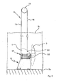
- FIG. 1 to 5 shown Horizontalrrockwerk has a generally designated by the reference M mounting unit.
- the assembly unit M comprises a submersible motor 1, which drives a propeller 3 via a gearbox 2 such that a horizontal flow directed by the propeller 3 in the direction of the submersible motor 1 can be generated.
- a first flow guide 4 From the submersible motor 1 extends in the vertical direction, a first flow guide 4.
- the mounting unit M on a first coupling device.
- the first coupling device comprises a first coupling element 5 extending in the submersible motor 1 and a third coupling element 6 extending from the transmission 2.
- Fig. 1 to 5 is denoted by the reference numeral A is a receptacle in which two plate-like second flow guide elements 7 are connected to each other by means of a first support plate 8 and a second support plate 9.
- the second flow guide elements 7 are connected to one another by a first connection element 10 and a second connection element 11.
- the first 8 and the second support plate 9 carry a second coupling device.
- the second coupling device comprises a second coupling element 12 extending from the first support plate and a fourth coupling element 13 extending from the second support plate.
- Reference numeral 14 denotes a first run of a circulating rope S, which extends between a first deflection roller 15 and the receptacle A stretches.
- a second run 16 extends from the first guide roller 15 to the upper attachment points B1 on the mounting unit M.
- the upper attachment points B1 are advantageously located on the first flow guide 4.
- the first run 14 of the rope S is by a first guide 17 on the receptacle A guided, which passes through the first 8 and the second support plate 9.
- Another end of the rope S is attached to a lower attachment point B2 on the mounting unit M in the region of the third coupling element 6.
- the assembly unit M is guided along the first run 14 by means of a second guide 18 attached to the first flow guide.
- the second guide 18 can be a slot guide, eye bolt or the like encompassing the first run 14: When using the slot guide shown in the figures, a pivoting of the mounting unit M from a horizontal position (see FIG Fig.
- the first guide 17 is expediently a bent tube passing through the first 8 and the second support plate 9 (not shown here).
- second deflection rollers may be provided.
- the first pulley 15 is mounted above a nominal sewage level on a bridge or rack (not shown). It can be driven for example by means of an electric motor.
- a bottom of a clarifier is in Fig. 5 denoted by the reference Bo.
- the function of the horizontal agitator is the following:
- the circulating cable S is moved clockwise about the first deflecting roller 15.
- the mounting unit M lowers in the direction of the receptacle A, being guided along the first run 14 by means of the second guide 18.
- Another guide is effected by the second run 16.
- An upper mounting point B1 on the mounting unit M is selected so that the mounting unit M assumes an inclined position during lowering.
- the inclined position is selected so that when lowering first the first coupling element 5 engages in the provided on the receptacle A second coupling element 12.
- the third coupling element is brought into engagement with the fourth coupling element 13 attached to the receptacle A.
- the mounting unit M assumes a substantially horizontal position. In this state, the third coupling element 6 is latched to the fourth coupling element 13.
- a disengagement of the mounting unit M of the recording A is done in reverse order by moving the revolving rope S counterclockwise about the first diverting pulley 15.
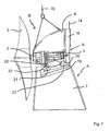
- the second flow guide elements 7 are connected to each other by means of a single third connecting element 19.
- the third connecting element 19 has, on its upper side facing the assembly unit M, a profile rail 20 with a trapezoidal or V-shaped profile (not shown here).
- Attached to the assembly unit M are two fifth coupling elements 21, the profile of which corresponds to the profile of the profile rail 20, such that the fifth coupling elements 21 can be placed on the profile rail 20 in a form-fitting manner.
- the profile rail 20 receiving third connecting element 19 is inclined in the direction of the propeller 3 downwardly attached to the second flow guide elements 7.
- the proposed horizontal agitator can be produced with little effort. In particular, it can be dispensed with the provision of a vertical column or a vertical pillar for guiding the mounting unit M. With the proposed horizontal agitator, a horizontal flow can be generated in a clarifier in a particularly efficient manner.
Landscapes
- Chemical & Material Sciences (AREA)
- Engineering & Computer Science (AREA)
- Life Sciences & Earth Sciences (AREA)
- Chemical Kinetics & Catalysis (AREA)
- Environmental & Geological Engineering (AREA)
- Water Supply & Treatment (AREA)
- Organic Chemistry (AREA)
- Hydrology & Water Resources (AREA)
- Biodiversity & Conservation Biology (AREA)
- Microbiology (AREA)
- Mechanical Engineering (AREA)
- General Engineering & Computer Science (AREA)
- Mixers Of The Rotary Stirring Type (AREA)
- Accessories For Mixers (AREA)
Priority Applications (1)
| Application Number | Priority Date | Filing Date | Title |
|---|---|---|---|
| PL13711875T PL2833992T3 (pl) | 2012-04-04 | 2013-03-20 | Mieszadło poziome |
Applications Claiming Priority (2)
| Application Number | Priority Date | Filing Date | Title |
|---|---|---|---|
| DE102012205579A DE102012205579A1 (de) | 2012-04-04 | 2012-04-04 | Horizontalrührwerk |
| PCT/EP2013/055838 WO2013149834A1 (de) | 2012-04-04 | 2013-03-20 | Horizontalrührwerk |
Publications (2)
| Publication Number | Publication Date |
|---|---|
| EP2833992A1 EP2833992A1 (de) | 2015-02-11 |
| EP2833992B1 true EP2833992B1 (de) | 2016-01-13 |
Family
ID=47997424
Family Applications (1)
| Application Number | Title | Priority Date | Filing Date |
|---|---|---|---|
| EP13711875.8A Active EP2833992B1 (de) | 2012-04-04 | 2013-03-20 | Horizontalrührwerk |
Country Status (16)
| Country | Link |
|---|---|
| US (1) | US9957800B2 (https=) |
| EP (1) | EP2833992B1 (https=) |
| JP (1) | JP6328608B2 (https=) |
| KR (1) | KR101920895B1 (https=) |
| CN (1) | CN104245106B (https=) |
| BR (1) | BR112014024944B1 (https=) |
| CA (1) | CA2867513C (https=) |
| DE (2) | DE102012205579A1 (https=) |
| DK (1) | DK2833992T3 (https=) |
| ES (1) | ES2563856T3 (https=) |
| HU (1) | HUE027258T2 (https=) |
| IL (1) | IL234745A (https=) |
| MX (1) | MX344231B (https=) |
| PL (1) | PL2833992T3 (https=) |
| TW (1) | TWI587918B (https=) |
| WO (1) | WO2013149834A1 (https=) |
Families Citing this family (2)
| Publication number | Priority date | Publication date | Assignee | Title |
|---|---|---|---|---|
| CN105347526A (zh) * | 2015-10-28 | 2016-02-24 | 桂林瑞丰环保微生物应用研究所 | 一种水平及纵向双向震荡式油水除油方法 |
| CN112156685A (zh) * | 2020-11-09 | 2021-01-01 | 中科广化(重庆)新材料研究院有限公司 | 用于污水处理的搅拌装置 |
Family Cites Families (19)
| Publication number | Priority date | Publication date | Assignee | Title |
|---|---|---|---|---|
| JPS5589092A (en) * | 1978-12-19 | 1980-07-05 | Ebara Mfg | Mixer for reserve tank |
| US4464259A (en) * | 1982-09-30 | 1984-08-07 | Air-O-Lator Corporation | Hydraulic horizontal mixer |
| US4581182A (en) * | 1985-02-21 | 1986-04-08 | Air-O-Lator Corporation | Submersible mixer with air injection |
| US4671872A (en) | 1986-03-18 | 1987-06-09 | Air-O-Lator Corporation | Aerator mast with azimuth lock and bottom stop |
| JPH0420497Y2 (https=) * | 1987-03-27 | 1992-05-11 | ||
| SE467292B (sv) * | 1990-10-05 | 1992-06-29 | Flygt Ab | Anordning foer att laett loesbart montera en draenkbar omroerare i en vaetskebehaallare |
| DE4120987C2 (de) * | 1991-06-25 | 1997-08-28 | Erwin Koeberle | Von außerhalb eines geschlossenen Flüssigkeitsbehälters, wie z.B. einer Biogasanlage, bedienbarer mechanischer Manipulator |
| DE4123664A1 (de) * | 1991-07-17 | 1993-01-21 | E & M Maschbau Gmbh | Fuehrungseinrichtung fuer ein tauchruehrwerk oder dergleichen |
| DE19528701A1 (de) * | 1995-08-04 | 1997-02-06 | Wilo Gmbh | Seilführung für Tauchpumpen |
| DE19543525C1 (de) * | 1995-11-22 | 1997-02-06 | Itt Flygt Pumpen Gmbh | Vorrichtung zum Handhaben von untergetaucht arbeitenden Aggregaten |
| DE19620986C1 (de) * | 1996-05-24 | 1997-09-25 | Abs Pump Center Gmbh | Einhängevorrichtung |
| DE19845545A1 (de) * | 1998-02-10 | 1999-08-12 | Fred Koch | Tauchmotor-Rührwerk |
| JP2002346359A (ja) * | 2001-05-29 | 2002-12-03 | Shin Meiwa Ind Co Ltd | プロペラ及び水中ミキサ |
| DE10150279A1 (de) * | 2001-10-05 | 2003-04-17 | Emu Unterwasserpumpen Gmbh | Tauchrührwerkanlage |
| DE10319760B4 (de) * | 2003-04-30 | 2015-05-13 | Abs Production Lohmar Gmbh | Einhängevorrichtung |
| JP2005199150A (ja) * | 2004-01-14 | 2005-07-28 | Shin Meiwa Ind Co Ltd | 水中ミキサ用据え付け装置 |
| JP4990591B2 (ja) * | 2006-09-29 | 2012-08-01 | 新明和工業株式会社 | 水中機器の昇降操作装置 |
| DE102007008134A1 (de) | 2007-02-19 | 2008-08-21 | Invent Umwelt- Und Verfahrenstechnik Ag | Horizontalrührwerk und Verfahren zum Erzeugen einer Strömung in einem Klärbecken mit dem Horizontalrührwerk |
| EP2689830B1 (de) * | 2012-07-26 | 2016-04-20 | Michael Niederbacher | Biogasanlage |
-
2012
- 2012-04-04 DE DE102012205579A patent/DE102012205579A1/de not_active Ceased
- 2012-04-04 DE DE202012013493.0U patent/DE202012013493U1/de not_active Expired - Lifetime
-
2013
- 2013-02-22 TW TW102106183A patent/TWI587918B/zh active
- 2013-03-20 CA CA2867513A patent/CA2867513C/en active Active
- 2013-03-20 BR BR112014024944-0A patent/BR112014024944B1/pt active IP Right Grant
- 2013-03-20 MX MX2014011632A patent/MX344231B/es active IP Right Grant
- 2013-03-20 HU HUE13711875A patent/HUE027258T2/en unknown
- 2013-03-20 JP JP2015503811A patent/JP6328608B2/ja active Active
- 2013-03-20 US US14/389,788 patent/US9957800B2/en active Active
- 2013-03-20 PL PL13711875T patent/PL2833992T3/pl unknown
- 2013-03-20 DK DK13711875.8T patent/DK2833992T3/en active
- 2013-03-20 ES ES13711875.8T patent/ES2563856T3/es active Active
- 2013-03-20 CN CN201380016422.1A patent/CN104245106B/zh active Active
- 2013-03-20 KR KR1020147026814A patent/KR101920895B1/ko active Active
- 2013-03-20 WO PCT/EP2013/055838 patent/WO2013149834A1/de not_active Ceased
- 2013-03-20 EP EP13711875.8A patent/EP2833992B1/de active Active
-
2014
- 2014-09-18 IL IL234745A patent/IL234745A/en active IP Right Grant
Also Published As
| Publication number | Publication date |
|---|---|
| ES2563856T3 (es) | 2016-03-16 |
| TWI587918B (zh) | 2017-06-21 |
| MX344231B (es) | 2016-12-08 |
| JP6328608B2 (ja) | 2018-05-23 |
| US20150063998A1 (en) | 2015-03-05 |
| KR20150002620A (ko) | 2015-01-07 |
| CN104245106B (zh) | 2016-10-12 |
| EP2833992A1 (de) | 2015-02-11 |
| WO2013149834A1 (de) | 2013-10-10 |
| DK2833992T3 (en) | 2016-04-11 |
| BR112014024944A2 (pt) | 2018-04-10 |
| CA2867513A1 (en) | 2013-10-10 |
| TW201341047A (zh) | 2013-10-16 |
| PL2833992T3 (pl) | 2016-07-29 |
| US9957800B2 (en) | 2018-05-01 |
| HUE027258T2 (en) | 2016-10-28 |
| IL234745A (en) | 2017-11-30 |
| DE102012205579A1 (de) | 2013-10-10 |
| DE202012013493U1 (de) | 2017-03-03 |
| JP2015514008A (ja) | 2015-05-18 |
| KR101920895B1 (ko) | 2019-02-13 |
| MX2014011632A (es) | 2014-10-17 |
| CA2867513C (en) | 2019-08-27 |
| CN104245106A (zh) | 2014-12-24 |
| BR112014024944B1 (pt) | 2020-12-15 |
Similar Documents
| Publication | Publication Date | Title |
|---|---|---|
| EP3548413B1 (de) | Aufzugsanlage und verfahren zum errichten einer aufzugsanlage | |
| WO1999033742A1 (de) | Seil-aufzug mit treibscheibe | |
| DE60009162T2 (de) | Kausche für flexibles flachseil | |
| EP2833992B1 (de) | Horizontalrührwerk | |
| EP2346771A1 (de) | Modernisierungsverfahren für aufzuganlagen | |
| EP3466866B1 (de) | Windenmontagerahmen und windenanordnung | |
| DE19501414A1 (de) | Vorrichtung zum Handhaben von untergetaucht arbeitenden Aggregaten | |
| EP0122549A1 (de) | Hebevorrichtung für elektrische Tauchpumpeneinheiten | |
| EP0144641B1 (de) | Montageaufsatz für Brunnenpumpe | |
| DE20203336U1 (de) | Vorrichtung zum Einbringen eines Gegenstandes in den Boden | |
| DE102014101581A1 (de) | Aufzuganlage | |
| AT10692U1 (de) | Hebe- und schwenkeinrichtung | |
| DE3490207T1 (de) | Schabevorrichtung für Absetzbecken | |
| EP2833993B1 (de) | Horizontalrührwerk | |
| DE102004061182A1 (de) | Scherenhubtisch | |
| DE19962298C2 (de) | Einpressvorrichtung für Rohre und Bohrgestänge | |
| EP4054967B1 (de) | Installationseinrichtung für eine verwendung in einem aufzugschacht | |
| DE102010050518A1 (de) | Haltevorrichtung für den Lastenträger einer Schachtförderanlage | |
| DE102006019261B4 (de) | Bohrgerät mit beweglicher Lünette | |
| DE19540945A1 (de) | Flächenbelüfter mit Hebevorrichtung | |
| EP1045811B1 (de) | Seil-aufzug mit treibscheibe | |
| DE102018129749B3 (de) | Belüftungssystem zum Belüften einer Flüssigkeit, insbesondere Abwasser, und Flüssigkeitsbehälter | |
| DE102004034589B3 (de) | Kettenzug | |
| EP0601297B1 (de) | An einer Führungseinrichtung absenkbare Umwälzeinrichtung | |
| DE102023000227A1 (de) | Maschinenraumloses Aufzugssystem mit Antrieb an der Aufzugskabine |
Legal Events
| Date | Code | Title | Description |
|---|---|---|---|
| PUAI | Public reference made under article 153(3) epc to a published international application that has entered the european phase |
Free format text: ORIGINAL CODE: 0009012 |
|
| 17P | Request for examination filed |
Effective date: 20140926 |
|
| AK | Designated contracting states |
Kind code of ref document: A1 Designated state(s): AL AT BE BG CH CY CZ DE DK EE ES FI FR GB GR HR HU IE IS IT LI LT LU LV MC MK MT NL NO PL PT RO RS SE SI SK SM TR |
|
| AX | Request for extension of the european patent |
Extension state: BA ME |
|
| DAX | Request for extension of the european patent (deleted) | ||
| GRAP | Despatch of communication of intention to grant a patent |
Free format text: ORIGINAL CODE: EPIDOSNIGR1 |
|
| INTG | Intention to grant announced |
Effective date: 20150918 |
|
| GRAS | Grant fee paid |
Free format text: ORIGINAL CODE: EPIDOSNIGR3 |
|
| GRAA | (expected) grant |
Free format text: ORIGINAL CODE: 0009210 |
|
| AK | Designated contracting states |
Kind code of ref document: B1 Designated state(s): AL AT BE BG CH CY CZ DE DK EE ES FI FR GB GR HR HU IE IS IT LI LT LU LV MC MK MT NL NO PL PT RO RS SE SI SK SM TR |
|
| REG | Reference to a national code |
Ref country code: GB Ref legal event code: FG4D Free format text: NOT ENGLISH |
|
| REG | Reference to a national code |
Ref country code: CH Ref legal event code: EP |
|
| REG | Reference to a national code |
Ref country code: IE Ref legal event code: FG4D Free format text: LANGUAGE OF EP DOCUMENT: GERMAN |
|
| REG | Reference to a national code |
Ref country code: AT Ref legal event code: REF Ref document number: 770137 Country of ref document: AT Kind code of ref document: T Effective date: 20160215 |
|
| REG | Reference to a national code |
Ref country code: DE Ref legal event code: R096 Ref document number: 502013001806 Country of ref document: DE |
|
| REG | Reference to a national code |
Ref country code: ES Ref legal event code: FG2A Ref document number: 2563856 Country of ref document: ES Kind code of ref document: T3 Effective date: 20160316 |
|
| REG | Reference to a national code |
Ref country code: SE Ref legal event code: TRGR Ref country code: FR Ref legal event code: PLFP Year of fee payment: 4 |
|
| REG | Reference to a national code |
Ref country code: DK Ref legal event code: T3 Effective date: 20160404 |
|
| REG | Reference to a national code |
Ref country code: NL Ref legal event code: FP |
|
| REG | Reference to a national code |
Ref country code: LT Ref legal event code: MG4D |
|
| PG25 | Lapsed in a contracting state [announced via postgrant information from national office to epo] |
Ref country code: GR Free format text: LAPSE BECAUSE OF FAILURE TO SUBMIT A TRANSLATION OF THE DESCRIPTION OR TO PAY THE FEE WITHIN THE PRESCRIBED TIME-LIMIT Effective date: 20160414 Ref country code: HR Free format text: LAPSE BECAUSE OF FAILURE TO SUBMIT A TRANSLATION OF THE DESCRIPTION OR TO PAY THE FEE WITHIN THE PRESCRIBED TIME-LIMIT Effective date: 20160113 Ref country code: NO Free format text: LAPSE BECAUSE OF FAILURE TO SUBMIT A TRANSLATION OF THE DESCRIPTION OR TO PAY THE FEE WITHIN THE PRESCRIBED TIME-LIMIT Effective date: 20160413 |
|
| PG25 | Lapsed in a contracting state [announced via postgrant information from national office to epo] |
Ref country code: PT Free format text: LAPSE BECAUSE OF FAILURE TO SUBMIT A TRANSLATION OF THE DESCRIPTION OR TO PAY THE FEE WITHIN THE PRESCRIBED TIME-LIMIT Effective date: 20160513 Ref country code: RS Free format text: LAPSE BECAUSE OF FAILURE TO SUBMIT A TRANSLATION OF THE DESCRIPTION OR TO PAY THE FEE WITHIN THE PRESCRIBED TIME-LIMIT Effective date: 20160113 Ref country code: LT Free format text: LAPSE BECAUSE OF FAILURE TO SUBMIT A TRANSLATION OF THE DESCRIPTION OR TO PAY THE FEE WITHIN THE PRESCRIBED TIME-LIMIT Effective date: 20160113 Ref country code: IS Free format text: LAPSE BECAUSE OF FAILURE TO SUBMIT A TRANSLATION OF THE DESCRIPTION OR TO PAY THE FEE WITHIN THE PRESCRIBED TIME-LIMIT Effective date: 20160513 Ref country code: LV Free format text: LAPSE BECAUSE OF FAILURE TO SUBMIT A TRANSLATION OF THE DESCRIPTION OR TO PAY THE FEE WITHIN THE PRESCRIBED TIME-LIMIT Effective date: 20160113 |
|
| REG | Reference to a national code |
Ref country code: DE Ref legal event code: R097 Ref document number: 502013001806 Country of ref document: DE |
|
| REG | Reference to a national code |
Ref country code: HU Ref legal event code: AG4A Ref document number: E027258 Country of ref document: HU |
|
| PG25 | Lapsed in a contracting state [announced via postgrant information from national office to epo] |
Ref country code: LU Free format text: LAPSE BECAUSE OF FAILURE TO SUBMIT A TRANSLATION OF THE DESCRIPTION OR TO PAY THE FEE WITHIN THE PRESCRIBED TIME-LIMIT Effective date: 20160320 Ref country code: MC Free format text: LAPSE BECAUSE OF FAILURE TO SUBMIT A TRANSLATION OF THE DESCRIPTION OR TO PAY THE FEE WITHIN THE PRESCRIBED TIME-LIMIT Effective date: 20160113 Ref country code: EE Free format text: LAPSE BECAUSE OF FAILURE TO SUBMIT A TRANSLATION OF THE DESCRIPTION OR TO PAY THE FEE WITHIN THE PRESCRIBED TIME-LIMIT Effective date: 20160113 |
|
| PLBE | No opposition filed within time limit |
Free format text: ORIGINAL CODE: 0009261 |
|
| STAA | Information on the status of an ep patent application or granted ep patent |
Free format text: STATUS: NO OPPOSITION FILED WITHIN TIME LIMIT |
|
| PG25 | Lapsed in a contracting state [announced via postgrant information from national office to epo] |
Ref country code: RO Free format text: LAPSE BECAUSE OF FAILURE TO SUBMIT A TRANSLATION OF THE DESCRIPTION OR TO PAY THE FEE WITHIN THE PRESCRIBED TIME-LIMIT Effective date: 20160113 Ref country code: SK Free format text: LAPSE BECAUSE OF FAILURE TO SUBMIT A TRANSLATION OF THE DESCRIPTION OR TO PAY THE FEE WITHIN THE PRESCRIBED TIME-LIMIT Effective date: 20160113 Ref country code: SM Free format text: LAPSE BECAUSE OF FAILURE TO SUBMIT A TRANSLATION OF THE DESCRIPTION OR TO PAY THE FEE WITHIN THE PRESCRIBED TIME-LIMIT Effective date: 20160113 |
|
| 26N | No opposition filed |
Effective date: 20161014 |
|
| PG25 | Lapsed in a contracting state [announced via postgrant information from national office to epo] |
Ref country code: BG Free format text: LAPSE BECAUSE OF FAILURE TO SUBMIT A TRANSLATION OF THE DESCRIPTION OR TO PAY THE FEE WITHIN THE PRESCRIBED TIME-LIMIT Effective date: 20160413 Ref country code: SI Free format text: LAPSE BECAUSE OF FAILURE TO SUBMIT A TRANSLATION OF THE DESCRIPTION OR TO PAY THE FEE WITHIN THE PRESCRIBED TIME-LIMIT Effective date: 20160113 |
|
| REG | Reference to a national code |
Ref country code: FR Ref legal event code: PLFP Year of fee payment: 5 |
|
| PG25 | Lapsed in a contracting state [announced via postgrant information from national office to epo] |
Ref country code: MT Free format text: LAPSE BECAUSE OF FAILURE TO SUBMIT A TRANSLATION OF THE DESCRIPTION OR TO PAY THE FEE WITHIN THE PRESCRIBED TIME-LIMIT Effective date: 20160113 |
|
| REG | Reference to a national code |
Ref country code: FR Ref legal event code: PLFP Year of fee payment: 6 |
|
| PG25 | Lapsed in a contracting state [announced via postgrant information from national office to epo] |
Ref country code: CY Free format text: LAPSE BECAUSE OF FAILURE TO SUBMIT A TRANSLATION OF THE DESCRIPTION OR TO PAY THE FEE WITHIN THE PRESCRIBED TIME-LIMIT Effective date: 20160113 Ref country code: MK Free format text: LAPSE BECAUSE OF FAILURE TO SUBMIT A TRANSLATION OF THE DESCRIPTION OR TO PAY THE FEE WITHIN THE PRESCRIBED TIME-LIMIT Effective date: 20160113 |
|
| PG25 | Lapsed in a contracting state [announced via postgrant information from national office to epo] |
Ref country code: TR Free format text: LAPSE BECAUSE OF FAILURE TO SUBMIT A TRANSLATION OF THE DESCRIPTION OR TO PAY THE FEE WITHIN THE PRESCRIBED TIME-LIMIT Effective date: 20160113 Ref country code: AL Free format text: LAPSE BECAUSE OF FAILURE TO SUBMIT A TRANSLATION OF THE DESCRIPTION OR TO PAY THE FEE WITHIN THE PRESCRIBED TIME-LIMIT Effective date: 20160113 |
|
| REG | Reference to a national code |
Ref country code: DE Ref legal event code: R079 Ref document number: 502013001806 Country of ref document: DE Free format text: PREVIOUS MAIN CLASS: B01F0007000000 Ipc: B01F0027000000 |
|
| PGFP | Annual fee paid to national office [announced via postgrant information from national office to epo] |
Ref country code: SE Payment date: 20250311 Year of fee payment: 13 |
|
| PGFP | Annual fee paid to national office [announced via postgrant information from national office to epo] |
Ref country code: DE Payment date: 20250319 Year of fee payment: 13 |
|
| PGFP | Annual fee paid to national office [announced via postgrant information from national office to epo] |
Ref country code: DK Payment date: 20250321 Year of fee payment: 13 Ref country code: NL Payment date: 20250324 Year of fee payment: 13 Ref country code: FI Payment date: 20250320 Year of fee payment: 13 |
|
| PGFP | Annual fee paid to national office [announced via postgrant information from national office to epo] |
Ref country code: HU Payment date: 20250317 Year of fee payment: 13 |
|
| PGFP | Annual fee paid to national office [announced via postgrant information from national office to epo] |
Ref country code: IE Payment date: 20250320 Year of fee payment: 13 |
|
| PGFP | Annual fee paid to national office [announced via postgrant information from national office to epo] |
Ref country code: BE Payment date: 20250320 Year of fee payment: 13 Ref country code: AT Payment date: 20250319 Year of fee payment: 13 |
|
| PGFP | Annual fee paid to national office [announced via postgrant information from national office to epo] |
Ref country code: PL Payment date: 20250314 Year of fee payment: 13 Ref country code: FR Payment date: 20250324 Year of fee payment: 13 Ref country code: CZ Payment date: 20250311 Year of fee payment: 13 |
|
| PGFP | Annual fee paid to national office [announced via postgrant information from national office to epo] |
Ref country code: GB Payment date: 20250324 Year of fee payment: 13 |
|
| PGFP | Annual fee paid to national office [announced via postgrant information from national office to epo] |
Ref country code: ES Payment date: 20250416 Year of fee payment: 13 |
|
| PGFP | Annual fee paid to national office [announced via postgrant information from national office to epo] |
Ref country code: IT Payment date: 20250331 Year of fee payment: 13 |
|
| PGFP | Annual fee paid to national office [announced via postgrant information from national office to epo] |
Ref country code: CH Payment date: 20250401 Year of fee payment: 13 |