EP2833993B1 - Horizontalrührwerk - Google Patents
Horizontalrührwerk Download PDFInfo
- Publication number
- EP2833993B1 EP2833993B1 EP13713784.0A EP13713784A EP2833993B1 EP 2833993 B1 EP2833993 B1 EP 2833993B1 EP 13713784 A EP13713784 A EP 13713784A EP 2833993 B1 EP2833993 B1 EP 2833993B1
- Authority
- EP
- European Patent Office
- Prior art keywords
- flow guide
- submersible motor
- guide elements
- propeller
- horizontal agitator
- Prior art date
- Legal status (The legal status is an assumption and is not a legal conclusion. Google has not performed a legal analysis and makes no representation as to the accuracy of the status listed.)
- Active
Links
- 230000008878 coupling Effects 0.000 claims description 15
- 238000010168 coupling process Methods 0.000 claims description 15
- 238000005859 coupling reaction Methods 0.000 claims description 15
- 239000002184 metal Substances 0.000 claims description 3
- 230000005540 biological transmission Effects 0.000 description 1
- 238000012423 maintenance Methods 0.000 description 1
- 239000002351 wastewater Substances 0.000 description 1
Images


Classifications
-
- B—PERFORMING OPERATIONS; TRANSPORTING
- B01—PHYSICAL OR CHEMICAL PROCESSES OR APPARATUS IN GENERAL
- B01F—MIXING, e.g. DISSOLVING, EMULSIFYING OR DISPERSING
- B01F27/00—Mixers with rotary stirring devices in fixed receptacles; Kneaders
- B01F27/60—Mixers with rotary stirring devices in fixed receptacles; Kneaders with stirrers rotating about a horizontal or inclined axis
- B01F27/71—Mixers with rotary stirring devices in fixed receptacles; Kneaders with stirrers rotating about a horizontal or inclined axis with propellers
-
- B—PERFORMING OPERATIONS; TRANSPORTING
- B01—PHYSICAL OR CHEMICAL PROCESSES OR APPARATUS IN GENERAL
- B01F—MIXING, e.g. DISSOLVING, EMULSIFYING OR DISPERSING
- B01F27/00—Mixers with rotary stirring devices in fixed receptacles; Kneaders
- B01F27/25—Mixers with both stirrer and drive unit submerged in the material being mixed
- B01F27/251—Vertical beam constructions therefor
-
- B—PERFORMING OPERATIONS; TRANSPORTING
- B01—PHYSICAL OR CHEMICAL PROCESSES OR APPARATUS IN GENERAL
- B01F—MIXING, e.g. DISSOLVING, EMULSIFYING OR DISPERSING
- B01F27/00—Mixers with rotary stirring devices in fixed receptacles; Kneaders
- B01F27/60—Mixers with rotary stirring devices in fixed receptacles; Kneaders with stirrers rotating about a horizontal or inclined axis
- B01F27/71—Mixers with rotary stirring devices in fixed receptacles; Kneaders with stirrers rotating about a horizontal or inclined axis with propellers
- B01F27/711—Mixers with rotary stirring devices in fixed receptacles; Kneaders with stirrers rotating about a horizontal or inclined axis with propellers co-operating with stationary guiding means, e.g. baffles
-
- B—PERFORMING OPERATIONS; TRANSPORTING
- B01—PHYSICAL OR CHEMICAL PROCESSES OR APPARATUS IN GENERAL
- B01F—MIXING, e.g. DISSOLVING, EMULSIFYING OR DISPERSING
- B01F2215/00—Auxiliary or complementary information in relation with mixing
- B01F2215/04—Technical information in relation with mixing
- B01F2215/0413—Numerical information
- B01F2215/0418—Geometrical information
- B01F2215/0422—Numerical values of angles
Definitions
- the invention relates to a horizontal agitator for generating a flow in a clarifier according to the preamble of claim 1.
- Such a horizontal agitator is from the WO 2008/101633 A1 known.
- the known horizontal agitator is accommodated on a carriage, which is movable vertically along a columnar frame. With the known horizontal agitator directed with a good efficiency in the direction of the frame horizontal flow can be generated. However, there is a need to further improve the efficiency of horizontal flow generation.
- the object of the invention is to eliminate the disadvantages of the prior art.
- a horizontal agitator is to be specified, which allows the generation of a horizontal flow with further improved efficiency.
- the submersible motor is supported via at least two first flow guide on a bottom of the clarifier.
- two first flow guide elements are used for supporting the submersible motor, can be dispensed with known in the prior art frame for supporting the submersible motor.
- the proposed horizontal agitator allows a particularly efficient production of a horizontal flow. It is also easy and inexpensive to produce.
- the term "axial plane" is understood to mean a plane containing the substantially horizontal axis of the propeller.
- the first flow guide elements are connected to each other via at least one carrier plate receiving the submersible motor.
- the first flow guide elements each extend at an angle of 90 ° to 140 °, preferably 100 ° to 120 °, of the carrier plate. Particularly in the case of a spreading away of the flow guide elements pointing away from one another at an angle of more than 90 ° from the carrier plate, a particularly stable support of the submersible motor can be achieved.
- the first flow guide and / or the at least one support plate made of folded sheet metal.
- breakthroughs are provided in at least one of the walls of the double wall to prevent air pockets within the double wall.
- the first flow guide elements are connected to each other at the bottom with at least one connecting element.
- the at least one support plate forms the first flow guide elements extending therefrom and the at least one connecting element has a tunnel-like structure, which is particularly stable.
- a second flow guide is provided, which extends in a direction away from the bottom of the clarifier direction of a mounted on the support plate support structure or the submersible motor.
- the provision of the second flow guide contributes to an improved alignment of the horizontal flow.
- the carrier plate with the first flow guide attached thereto forms a receptacle on which a mounting unit formed by the submersible motor and the propeller is detachably fastened by means of a coupling device.
- the assembly unit expediently also comprises the second flow-guiding element.
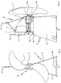
- a propeller 1 is connected via a gear 2 to a submersible motor 3.
- the submersible motor 3 is operated in such a way that a flow directed from the propeller 1 to the submersible motor 3 is generated.
- the propeller 1 forms together with the submersible motor 3 and possibly provided gear 2, a mounting unit which is supported on a front 4a and a rear support plate 4b. From the front 4a and the rear support plate 4b each first flow guide 5 extend at an angle of about 100 ° to 120 °.
- the first flow guide elements 5 are plate-like. Their planes are approximately parallel to an axis of the propeller. 1
- the front 4a and the rear support plate 4b and the first flow guide 5 are advantageously made of folded sheets.
- the support plates 4a, 4b and / or the flow elements 5 may be double-walled.
- a connection of the folded sheets expediently by means of rivets.
- a receptacle A produced in this way has excellent stability.
- the first flow guide elements 5 are expediently connected to a front 6a and a rear connecting element 6b.
- the front 6a and the rear connecting element 6b each have a flat inflow surface and downstream of a steeply sloping outflow surface.
- the mounting unit designated by the reference M has a second flow guide 7, which extends vertically above the submersible motor 3 and has a curved leading edge.
- the mounting unit M is detachably connected to a receptacle A which comprises the support plates 4a, 4b, the first flow guide elements 5 extending therefrom and the connecting elements 6a, 6b.
- a first 8a and a second coupling element 8b are attached to the front 4a and the rear support plate 4b.
- a third coupling element 9a corresponding to the first coupling element 8a and a corresponding fourth coupling element 9b are attached to the second coupling element 8b.
- the reference numeral 10 denotes a rope. From the second flow guide 7, a guide 11, preferably a slot guide, with which the mounting element M is guided along the cable 10 extends.
- a further cable 12 of the mounting unit M may be attached.
- a coupling between the receptacle A and the mounting element M caused by the coupling elements 8a, 8b, 9a, 9b can be released and the mounting element M guided along the cable 10 and lifted out of the clarifier.
- one end of the cable 10 can be guided by the rear 4b and the front support plate 4a and fixed to the mounting unit M in the region of the third coupling element 9a.
- the other end of the rope 10 can be guided over a deflection roller mounted above the clarifier (not shown here) and fixed at the attachment point.
- the cable 10 together with the other cable 12 form a cable with which the mounting unit M when lowering in the direction of the receptacle A guided and there by cooperation of the coupling elements 8a, 8b, 9a, 9b can be engaged.
Description
- Die Erfindung betrifft ein Horizontalrührwerk zum Erzeugen einer Strömung in einem Klärbecken nach dem Oberbegriff des Patentanspruch 1.
- Ein solches Horizontalrührwerk ist aus der
WO 2008/101633 A1 bekannt. Das bekannte Horizontalrührwerk ist auf einem Schlitten aufgenommen, der vertikal entlang eines säulenartigen Gestells verfahrbar ist. Mit dem bekannten Horizontalrührwerk kann mit guter Effizienz eine in Richtung des Gestells gerichtete Horizontalströmung erzeugt werden. Gleichwohl besteht das Bedürfnis, die Effizienz der Erzeugung der Horizontalströmung weiter zu verbessern. - Aufgabe der Erfindung ist es, die Nachteile nach dem Stand der Technik zu beseitigen. Insbesondere soll ein Horizontalrührwerk angegeben werden, welches die Erzeugung einer Horizontalströmung mit weiter verbesserter Effizienz ermöglicht.
- Diese Aufgabe wird durch die Merkmale des Anspruchs 1 gelöst. Zweckmäßige Ausgestaltungen der Erfindung ergeben sich aus den Merkmalen der Ansprüche 1 bis 5.
- Nach Maßgabe der Erfindung wird vorgeschlagen, dass der Tauchmotor über zumindest zwei erste Strömungsleitelemente auf einem Boden des Klärbeckens abgestützt ist. Indem zum Abstützen des Tauchmotors nunmehr zwei erste Strömungsleitelemente verwendet werden, kann auf das nach dem Stand der Technik bekannte Gestell zum Abstützen des Tauchmotors verzichtet werden.
- Infolge dessen fällt der durch das Gestell bedingte Strömungswiderstand weg. Das vorgeschlagene Horizontalrührwerk ermöglicht eine besonders effiziente Herstellung einer Horizontalströmung. Es ist überdies einfach und kostengünstig herstellbar. - Unter dem Begriff "Axialebene" wird eine Ebene verstanden, welche die im Wesentlichen horizontal verlaufende Achse des Propellers enthält.
- Nach einer vorteilhaften Ausgestaltung sind die ersten Strömungsleitelemente über zumindest eine den Tauchmotor aufnehmende Trägerplatte miteinander verbunden. Die ersten Strömungsleitelemente erstrecken sich jeweils in einem Winkel von 90° bis 140°, vorzugweise 100° bis 120°, von der Trägerplatte. Insbesondere bei einer voneinander weg weisenden Abspreizung der Strömungsleitelemente in einem Winkel von mehr als 90° von der Trägerplatte kann eine besonders stabile Abstützung des Tauchmotors erreicht werden.
- Nach einer weiteren vorteilhaften Ausgestaltung sind die ersten Strömungsleitelemente und/oder die zumindest eine Trägerplatte aus gekantetem Blech hergestellt. Insbesondere hat es sich als vorteilhaft erwiesen, die ersten Strömungsleitelemente und/oder die zumindest eine Trägerplatte doppelwandig aus gekantetem Blech auszugestalten. Im Falle einer doppelwandigen Ausbildung sind in zumindest einer der Wände der Doppelwand Durchbrüche zur Vermeidung von Lufteinschlüssen innerhalb der Doppelwand vorgesehen.
- Nach der Erfindung sind die ersten Strömungsleitelemente bodenseitig mit zumindest einem Verbindungselement miteinander verbunden. Damit bildet die zumindest eine Trägerplatte, die davon sich erstreckenden ersten Strömungsleitelemente sowie das zumindest eine Verbindungelement eine tunnelartige Struktur, welche besonders stabil ist.
- Nach einer weiteren Ausgestaltung ist ein zweites Strömungsleitelement vorgesehen, welches sich in einer vom Boden des Klärbeckens wegweisende Richtung von einer auf der Trägerplatte angebrachten Stützstruktur oder vom Tauchmotor erstreckt. Das Vorsehen des zweiten Strömungsleitelements trägt zu einer verbesserten Ausrichtung der Horizontalströmung bei.
- Nach der Erfindung bildet die Trägerplatte mit dem daran angebrachten ersten Strömungsleitelement eine Aufnahme, auf der eine aus dem Tauchmotor und dem Propeller gebildete Montageeinheit mittels einer Kupplungseinrichtung lösbar befestigt ist. Die Montageeinheit umfasst zweckmäßigerweise auch das zweite Strömungsleitelement. Die lösbare Befestigung des Montageelements an der Aufnahme ermöglicht eine besonders einfache Wartung und/oder Reparatur der Montageeinheit. Die Montageeinheit kann beispielsweise mit einem Seilzug von der Aufnahme gelöst und dann in eine Position oberhalb eines Niveaus eines im Klärbecken aufgenommen Abwassers gehoben werden.
- Nachfolgend wird ein Ausführungsbeispiel der Erfindung anhand der Zeichnungen näher erläutert. Es zeigen:
- Fig. 1
- eine perspektivische Ansicht des Horizontalrührwerks,
- Fig. 2
- eine Schnittansicht gemäß
Fig. 1 , - Fig. 3
- eine Vorderansicht gemäß
Fig. 1 , - Fig. 4
- eine Seitenansicht gemäß
Fig. 1 , - Fig. 5
- eine Draufsicht gemäß
Fig. 1 und - Fig. 6
- eine Rückansicht gemäß
Fig. 1 . - Bei dem in den Figuren gezeigten Horizontalrührwerk ist ein Propeller 1 über ein Getriebe 2 mit einem Tauchmotor 3 verbunden. Der Tauchmotor 3 wird derart betrieben, dass eine vom Propeller 1 zum Tauchmotor 3 hin gerichtet Strömung erzeugt wird.
- Der Propeller 1 bildet samt Tauchmotor 3 und ggf. vorgesehenem Getriebe 2 eine Montageeinheit, die auf einer vorderen 4a und einer hinteren Trägerplatte 4b abgestützt ist. Von der vorderen 4a und der hinteren Trägerplatte 4b erstrecken sich jeweils erste Strömungsleitelemente 5 in einem Winkel von etwa 100° bis 120°. Die ersten Strömungsleitelemente 5 sind plattenartig ausgebildet. Deren Ebenen verlaufen etwa parallel zu einer Achse des Propellers 1.
- Die vordere 4a und die hintere Trägerplatte 4b sowie die ersten Strömungsleitelemente 5 sind vorteilhafterweise aus gekanteten Blechen hergestellt. Zur Verbesserung der Stabilität können die Trägerplatten 4a, 4b und/oder die Strömungselemente 5 doppelwandig ausgebildet sein. Dabei erfolgt eine Verbindung der gekanteten Bleche zweckmäßigerweise mittels Nieten. Eine solchermaßen hergestellte Aufnahme A weist eine hervorragende Stabilität auf.
- Im Bereich des Bodens B des Klärbeckens sind die ersten Strömungsleitelemente 5 zweckmäßigerweise mit einem vorderen 6a und einem hinteren Verbindungselement 6b verbunden. Das vordere 6a und das hintere Verbindungselement 6b weisen jeweils eine flache Anströmfläche und stromabwärts eine steil abfallende Abströmfläche auf.
- Die mit dem Bezugszeichen M bezeichnete Montageeinheit weist ein zweites Strömungsleitelement 7 auf, welches sich vertikal oberhalb des Tauchmotors 3 erstreckt und eine gebogene Anströmkante aufweist.
- Die Montageeinheit M ist lösbar mit einer Aufnahme A verbunden, welche die Trägerplatten 4a, 4b, die davon sich erstreckenden ersten Strömungsleitelemente 5 und die Verbindungselemente 6a, 6b umfasst. Zur lösbaren Verbindung der Montageeinheit M mit der Aufnahme A sind an der vorderen 4a und der hinteren Trägerplatte 4b ein erstes 8a und ein zweites Kupplungselement 8b angebracht. Am Montageelement M sind ein zum ersten Kupplungselement 8a korrespondierendes drittes Kupplungselement 9a und ein zum zweiten Kupplungselement 8b ein korrespondierendes viertes Kupplungselement 9b angebracht.
- Mit dem Bezugszeichen 10 ist ein Seil bezeichnet. Vom zweiten Strömungsleitelement 7 erstreckt sich eine Führung 11, vorzugsweise eine Schlitzführung, mit der das Montageelement M entlang des Seils 10 geführt ist.
- Zum Abheben der Montageeinheit M kann ein weiteres Seil 12 der Montageeinheit M angebracht sein. Durch Ausübung einer Zugspannung mit dem weiteren Seil 12 kann eine durch die Kupplungselemente 8a, 8b, 9a, 9b bewirkte Kupplung zwischen der Aufnahme A und dem Montageelement M gelöst und das Montageelement M entlang des Seils 10 geführt und aus dem Klärbecken gehoben werden.
- Wie aus
Fig. 2 ersichtlich ist, kann ein Ende des Seils 10 durch die hintere 4b und die vordere Trägerplatte 4a geführt und im Bereich des dritten Kupplungselements 9a an der Montageeinheit M befestigt sein. Das andere Ende des Seils 10 kann über eine oberhalb des Klärbeckens angebrachte Umlenkrolle (hier nicht gezeigt) geführt und am Befestigungspunkt befestigt sein. Damit kann das Seil 10 zusammen mit dem weiteren Seil 12 einen Seilzug bilden, mit dem die Montageeinheit M beim Absenken in Richtung der Aufnahme A geführt und dort durch Zusammenwirken der Kupplungselemente 8a, 8b, 9a, 9b eingekuppelt werden kann. -
- 1
- Propeller
- 2
- Getriebe
- 3
- Tauchmotor
- 4a
- erste Trägerplatte
- 4b
- zweite Trägerplatte
- 5
- erstes Strömungsleitelement
- 6a
- erstes Verbindungselement
- 6b
- zweites Verbindungselement
- 7
- zweites Strömungsleitelement
- 8a
- erstes Kupplungselement
- 8b
- zweites Kupplungselement
- 9a
- drittes Kupplungselement
- 9b
- viertes Kupplungselement
- 10
- Seil
- 11
- Führungselement
- 12
- weiteres Seil
- A
- Aufnahme
- B
- Boden
- M
- Montageeinheit
Claims (5)
- Horizontalrührwerk zum Erzeugen einer Strömung in einem Klärbecken, bei dem ein Propeller (1) mit einem axial dazu versetzt angeordneten Tauchmotor (3) verbunden ist, wobei der Propeller (1) und der Tauchmotor (3) derart ausgestaltet sind, dass beim Betrieb des Tauchmotors (3) eine vom Propeller (1) zum Tauchmotor (3) hin gerichtete Strömung erzeugt wird, und wobei stromabwärts des Propellers (1) sich in mindestens einer im Wesentlichen parallel zur Propellerachse verlaufenden Axialebene erstreckende, plattenförmige Strömungsleitelemente (5, 7) vorgesehen sind,
dadurch gekennzeichnet, dass
der Tauchmotor (3) über zumindest zwei erste Strömungsleitelemente (5) auf einem Boden (B) des Klärbeckens abgestützt ist,
wobei die ersten Strömungsleitelemente (5) über zumindest eine den Tauchmotor (3) aufnehmende Trägerplatte (4a, 4b) miteinander verbunden sind, wobei die Trägerplatte (4a, 4b) mit den daran angebrachten ersten Strömungsleitelementen (5) eine Aufnahme (A) bildet, auf der eine aus dem Tauchmotor (3) und dem Propeller (1) gebildete Montageeinheit (M) mittels einer Kupplungseinrichtung (8a, 8b, 9a, 9b) lösbar befestigt ist. - Horizontalrührwerk nach Anspruch 1, wobei sich die ersten Strömungsleitelemente (5) jeweils in einem Winkel von 90° bis 140°, vorzugsweise 100° bis 120°, von der Trägerplatte (4a, 4b) erstrecken.
- Horizontalrührwerk nach einem der vorhergehenden Ansprüche, wobei die ersten Strömungsleitelemente (5) und/oder die zumindest eine Trägerplatte (4a, 4b) aus gekantetem Blech hergestellt sind.
- Horizontalrührwerk nach einem der vorhergehenden Ansprüche, wobei die ersten Strömungsleitelemente (5) bodenseitig mit zumindest einem Verbindungselement (6a, 6b) miteinander verbunden sind.
- Horizontalrührwerk nach einem der vorhergehenden Ansprüche, wobei ein zweites Strömungsleitelement (7) vorgesehen ist, welches sich in einer vom Boden (B) des Klärbeckens wegweisenden Richtung von einer auf der Trägerplatte (4a, 4b) angebrachten Stützstruktur oder vom Tauchmotor (3) erstreckt.
Applications Claiming Priority (2)
| Application Number | Priority Date | Filing Date | Title |
|---|---|---|---|
| DE102012205577A DE102012205577B3 (de) | 2012-04-04 | 2012-04-04 | Horizontalrührwerk |
| PCT/EP2013/055837 WO2013149833A1 (de) | 2012-04-04 | 2013-03-20 | Horizontalrührwerk |
Publications (2)
| Publication Number | Publication Date |
|---|---|
| EP2833993A1 EP2833993A1 (de) | 2015-02-11 |
| EP2833993B1 true EP2833993B1 (de) | 2016-04-27 |
Family
ID=48045438
Family Applications (1)
| Application Number | Title | Priority Date | Filing Date |
|---|---|---|---|
| EP13713784.0A Active EP2833993B1 (de) | 2012-04-04 | 2013-03-20 | Horizontalrührwerk |
Country Status (17)
| Country | Link |
|---|---|
| US (1) | US9687798B2 (de) |
| EP (1) | EP2833993B1 (de) |
| JP (1) | JP6180503B2 (de) |
| KR (1) | KR101920896B1 (de) |
| CN (1) | CN104245105B (de) |
| BR (1) | BR112014024938B1 (de) |
| CA (1) | CA2867692C (de) |
| DE (1) | DE102012205577B3 (de) |
| DK (1) | DK2833993T3 (de) |
| ES (1) | ES2579348T3 (de) |
| HU (1) | HUE029748T2 (de) |
| IL (1) | IL234744A (de) |
| MX (1) | MX344660B (de) |
| PL (1) | PL2833993T3 (de) |
| TW (1) | TWI587917B (de) |
| WO (1) | WO2013149833A1 (de) |
| ZA (1) | ZA201406742B (de) |
Families Citing this family (1)
| Publication number | Priority date | Publication date | Assignee | Title |
|---|---|---|---|---|
| US9855561B1 (en) * | 2010-09-20 | 2018-01-02 | Robert P. Stahl | Apparatus for breaking up clumps of granular material in a storage bin |
Family Cites Families (14)
| Publication number | Priority date | Publication date | Assignee | Title |
|---|---|---|---|---|
| JPS5589092A (en) * | 1978-12-19 | 1980-07-05 | Ebara Mfg | Mixer for reserve tank |
| US4566801A (en) * | 1984-10-18 | 1986-01-28 | General Signal Corporation | Submersible mixer alignable in a horizontal or vertical mode |
| JPH0331392Y2 (de) * | 1987-04-06 | 1991-07-03 | ||
| JPH0427536Y2 (de) * | 1987-09-26 | 1992-07-02 | ||
| SE8802902L (sv) * | 1988-08-16 | 1990-02-17 | Flygt Ab | Straalring foer omroerare |
| DE19501414A1 (de) * | 1995-01-19 | 1996-07-25 | Itt Flygt Pumpen Gmbh | Vorrichtung zum Handhaben von untergetaucht arbeitenden Aggregaten |
| DE19620986C1 (de) * | 1996-05-24 | 1997-09-25 | Abs Pump Center Gmbh | Einhängevorrichtung |
| CN2455711Y (zh) * | 2000-12-19 | 2001-10-24 | 哈尔滨工程大学 | 复合式水下曝气机 |
| JP2005199150A (ja) * | 2004-01-14 | 2005-07-28 | Shin Meiwa Ind Co Ltd | 水中ミキサ用据え付け装置 |
| CN2734319Y (zh) * | 2004-09-07 | 2005-10-19 | 佛山安德里茨技术有限公司 | 一种稀释搅拌器 |
| DE102007008135A1 (de) * | 2007-02-19 | 2008-08-21 | Invent Umwelt-Und Verfahrenstechnik Ag | Horizontalrührwerk und Verfahren zum Erzeugen einer Strömung in einem Klärbecken mit dem Horizontalrührwerk |
| DE102007008134A1 (de) | 2007-02-19 | 2008-08-21 | Invent Umwelt- Und Verfahrenstechnik Ag | Horizontalrührwerk und Verfahren zum Erzeugen einer Strömung in einem Klärbecken mit dem Horizontalrührwerk |
| DK2125180T3 (da) * | 2007-02-19 | 2011-04-26 | Invent Umwelt & Verfahrenstech | Horisontalt røreværk og indretning til frembringelse af en strøm i et klaringsbassin med det horisontale røreværk |
| US20100066089A1 (en) * | 2008-09-12 | 2010-03-18 | Bruce Best | Subsea turbine with a peripheral drive |
-
2012
- 2012-04-04 DE DE102012205577A patent/DE102012205577B3/de active Active
-
2013
- 2013-02-22 TW TW102106182A patent/TWI587917B/zh active
- 2013-03-20 HU HUE13713784A patent/HUE029748T2/en unknown
- 2013-03-20 JP JP2015503810A patent/JP6180503B2/ja active Active
- 2013-03-20 PL PL13713784.0T patent/PL2833993T3/pl unknown
- 2013-03-20 DK DK13713784.0T patent/DK2833993T3/en active
- 2013-03-20 KR KR1020147026816A patent/KR101920896B1/ko active IP Right Grant
- 2013-03-20 MX MX2014011633A patent/MX344660B/es active IP Right Grant
- 2013-03-20 EP EP13713784.0A patent/EP2833993B1/de active Active
- 2013-03-20 US US14/389,792 patent/US9687798B2/en active Active
- 2013-03-20 WO PCT/EP2013/055837 patent/WO2013149833A1/de active Application Filing
- 2013-03-20 BR BR112014024938-5A patent/BR112014024938B1/pt active IP Right Grant
- 2013-03-20 CA CA2867692A patent/CA2867692C/en active Active
- 2013-03-20 CN CN201380016050.2A patent/CN104245105B/zh active Active
- 2013-03-20 ES ES13713784.0T patent/ES2579348T3/es active Active
-
2014
- 2014-09-15 ZA ZA2014/06742A patent/ZA201406742B/en unknown
- 2014-09-18 IL IL234744A patent/IL234744A/en active IP Right Grant
Also Published As
| Publication number | Publication date |
|---|---|
| KR20140140558A (ko) | 2014-12-09 |
| MX2014011633A (es) | 2014-10-17 |
| BR112014024938A2 (pt) | 2018-04-17 |
| ZA201406742B (en) | 2015-12-23 |
| US20150078121A1 (en) | 2015-03-19 |
| HUE029748T2 (en) | 2017-04-28 |
| WO2013149833A1 (de) | 2013-10-10 |
| DK2833993T3 (en) | 2016-08-15 |
| CN104245105A (zh) | 2014-12-24 |
| KR101920896B1 (ko) | 2018-11-21 |
| JP2015514007A (ja) | 2015-05-18 |
| BR112014024938B1 (pt) | 2020-12-15 |
| IL234744A (en) | 2017-11-30 |
| PL2833993T3 (pl) | 2016-10-31 |
| TWI587917B (zh) | 2017-06-21 |
| ES2579348T3 (es) | 2016-08-10 |
| JP6180503B2 (ja) | 2017-08-16 |
| MX344660B (es) | 2017-01-04 |
| CN104245105B (zh) | 2016-03-23 |
| CA2867692A1 (en) | 2013-10-10 |
| CA2867692C (en) | 2019-08-13 |
| DE102012205577B3 (de) | 2013-06-06 |
| EP2833993A1 (de) | 2015-02-11 |
| US9687798B2 (en) | 2017-06-27 |
| TW201350196A (zh) | 2013-12-16 |
Similar Documents
| Publication | Publication Date | Title |
|---|---|---|
| DE602005004913T2 (de) | Anordnung für eine fahrzeugseitenverkleidung und fahrzeug mit einer solchen seitenverkleidung | |
| EP2060486B1 (de) | Ruder für Schiffe mit höheren Geschwindigkeiten mit einem kavitationsreduzierenden, twistierten, insbesondere Vollschweberuder | |
| DE202009001101U1 (de) | Ruderanordnung für Schiffe mit höheren Geschwindigkeiten mit einem kavitationsreduzierenden, twistierten, insbesondere Vollschweberuder | |
| DE102008039949B4 (de) | Querträger für ein Nutzfahrzeug | |
| EP2531383A1 (de) | Gurtaufrollerrahmen | |
| EP2508407B1 (de) | Gerüst, insbesondere für elektrische Einrichtungen in einem Schienenfahrzeug, und Verfahren zur Herstellung des Gerüsts | |
| DE102007008134A1 (de) | Horizontalrührwerk und Verfahren zum Erzeugen einer Strömung in einem Klärbecken mit dem Horizontalrührwerk | |
| EP3658447B1 (de) | Trägeranordnung für seitliche gepäckbehältnisse eines motorrades | |
| EP2977298B1 (de) | Frontendmodul | |
| DE7502788U (de) | Tragvorrichtung für den Schlitten eines SchweiBkopfes | |
| DE202008002576U1 (de) | Drehbar und/oder höhenverstellbar gelagerte Antriebseinheit | |
| EP2125180A1 (de) | Horizontalrührwerk und verfahren zum erzeugen einer strömung in einem klärbecken mit dem horizontalrührwerk | |
| EP2833993B1 (de) | Horizontalrührwerk | |
| DE102009051191A1 (de) | Nachrüstbares Rollenelement und Fuß für ein automatisches Lagersystem sowie Verfahren zum Verschieben eines automatischen Lagersystems | |
| EP0110270B1 (de) | Fahrzeugrahmen, insbesondere für ein Gleiskettenfahrzeug, und Getriebe hierfür | |
| DE102008020051A1 (de) | Crashbox für eine Karosserie eines Kraftwagens | |
| DE102009026297A1 (de) | Cockpitquerträger mit variablem Lenksäulenneigungswinkel | |
| EP2788098B1 (de) | Dekanter | |
| DE102014208303A1 (de) | Befestigungsvorrichtung zur Befestigung von Photovoltaikmodulen | |
| DE10234045B4 (de) | Stossfängeranordnung an einem Kraftfahrzeug | |
| WO2008101633A1 (de) | Horizontalrührwerk und verfahren zum erzeugen einer strömung in einem klärbecken mit dem horizontalrührwerk | |
| DE102007022912B4 (de) | Vorrichtung zum Sägen von Brettern | |
| EP2547626B1 (de) | Vorrichtung zum begasen einer in einem behandlungsbecken aufgenommenen suspension | |
| DE102006039012B4 (de) | Verbindungsanordnung eines Querträgers an einem tragenden Bauteil eines Lastkraftwagens | |
| DE102011105743A1 (de) | Biegegesenk |
Legal Events
| Date | Code | Title | Description |
|---|---|---|---|
| PUAI | Public reference made under article 153(3) epc to a published international application that has entered the european phase |
Free format text: ORIGINAL CODE: 0009012 |
|
| 17P | Request for examination filed |
Effective date: 20140926 |
|
| AK | Designated contracting states |
Kind code of ref document: A1 Designated state(s): AL AT BE BG CH CY CZ DE DK EE ES FI FR GB GR HR HU IE IS IT LI LT LU LV MC MK MT NL NO PL PT RO RS SE SI SK SM TR |
|
| AX | Request for extension of the european patent |
Extension state: BA ME |
|
| DAX | Request for extension of the european patent (deleted) | ||
| GRAP | Despatch of communication of intention to grant a patent |
Free format text: ORIGINAL CODE: EPIDOSNIGR1 |
|
| INTG | Intention to grant announced |
Effective date: 20151126 |
|
| GRAS | Grant fee paid |
Free format text: ORIGINAL CODE: EPIDOSNIGR3 |
|
| GRAA | (expected) grant |
Free format text: ORIGINAL CODE: 0009210 |
|
| AK | Designated contracting states |
Kind code of ref document: B1 Designated state(s): AL AT BE BG CH CY CZ DE DK EE ES FI FR GB GR HR HU IE IS IT LI LT LU LV MC MK MT NL NO PL PT RO RS SE SI SK SM TR |
|
| REG | Reference to a national code |
Ref country code: GB Ref legal event code: FG4D Free format text: NOT ENGLISH |
|
| REG | Reference to a national code |
Ref country code: CH Ref legal event code: EP |
|
| REG | Reference to a national code |
Ref country code: AT Ref legal event code: REF Ref document number: 794097 Country of ref document: AT Kind code of ref document: T Effective date: 20160515 |
|
| REG | Reference to a national code |
Ref country code: IE Ref legal event code: FG4D Free format text: LANGUAGE OF EP DOCUMENT: GERMAN |
|
| REG | Reference to a national code |
Ref country code: DE Ref legal event code: R096 Ref document number: 502013002798 Country of ref document: DE |
|
| REG | Reference to a national code |
Ref country code: SE Ref legal event code: TRGR |
|
| REG | Reference to a national code |
Ref country code: ES Ref legal event code: FG2A Ref document number: 2579348 Country of ref document: ES Kind code of ref document: T3 Effective date: 20160810 |
|
| REG | Reference to a national code |
Ref country code: DK Ref legal event code: T3 Effective date: 20160802 |
|
| REG | Reference to a national code |
Ref country code: NL Ref legal event code: FP |
|
| REG | Reference to a national code |
Ref country code: LT Ref legal event code: MG4D |
|
| PG25 | Lapsed in a contracting state [announced via postgrant information from national office to epo] |
Ref country code: NO Free format text: LAPSE BECAUSE OF FAILURE TO SUBMIT A TRANSLATION OF THE DESCRIPTION OR TO PAY THE FEE WITHIN THE PRESCRIBED TIME-LIMIT Effective date: 20160727 Ref country code: LT Free format text: LAPSE BECAUSE OF FAILURE TO SUBMIT A TRANSLATION OF THE DESCRIPTION OR TO PAY THE FEE WITHIN THE PRESCRIBED TIME-LIMIT Effective date: 20160427 |
|
| PG25 | Lapsed in a contracting state [announced via postgrant information from national office to epo] |
Ref country code: GR Free format text: LAPSE BECAUSE OF FAILURE TO SUBMIT A TRANSLATION OF THE DESCRIPTION OR TO PAY THE FEE WITHIN THE PRESCRIBED TIME-LIMIT Effective date: 20160728 Ref country code: PT Free format text: LAPSE BECAUSE OF FAILURE TO SUBMIT A TRANSLATION OF THE DESCRIPTION OR TO PAY THE FEE WITHIN THE PRESCRIBED TIME-LIMIT Effective date: 20160829 Ref country code: HR Free format text: LAPSE BECAUSE OF FAILURE TO SUBMIT A TRANSLATION OF THE DESCRIPTION OR TO PAY THE FEE WITHIN THE PRESCRIBED TIME-LIMIT Effective date: 20160427 Ref country code: RS Free format text: LAPSE BECAUSE OF FAILURE TO SUBMIT A TRANSLATION OF THE DESCRIPTION OR TO PAY THE FEE WITHIN THE PRESCRIBED TIME-LIMIT Effective date: 20160427 Ref country code: LV Free format text: LAPSE BECAUSE OF FAILURE TO SUBMIT A TRANSLATION OF THE DESCRIPTION OR TO PAY THE FEE WITHIN THE PRESCRIBED TIME-LIMIT Effective date: 20160427 |
|
| REG | Reference to a national code |
Ref country code: DE Ref legal event code: R097 Ref document number: 502013002798 Country of ref document: DE |
|
| PG25 | Lapsed in a contracting state [announced via postgrant information from national office to epo] |
Ref country code: SK Free format text: LAPSE BECAUSE OF FAILURE TO SUBMIT A TRANSLATION OF THE DESCRIPTION OR TO PAY THE FEE WITHIN THE PRESCRIBED TIME-LIMIT Effective date: 20160427 Ref country code: EE Free format text: LAPSE BECAUSE OF FAILURE TO SUBMIT A TRANSLATION OF THE DESCRIPTION OR TO PAY THE FEE WITHIN THE PRESCRIBED TIME-LIMIT Effective date: 20160427 Ref country code: RO Free format text: LAPSE BECAUSE OF FAILURE TO SUBMIT A TRANSLATION OF THE DESCRIPTION OR TO PAY THE FEE WITHIN THE PRESCRIBED TIME-LIMIT Effective date: 20160427 |
|
| PG25 | Lapsed in a contracting state [announced via postgrant information from national office to epo] |
Ref country code: SM Free format text: LAPSE BECAUSE OF FAILURE TO SUBMIT A TRANSLATION OF THE DESCRIPTION OR TO PAY THE FEE WITHIN THE PRESCRIBED TIME-LIMIT Effective date: 20160427 |
|
| PLBE | No opposition filed within time limit |
Free format text: ORIGINAL CODE: 0009261 |
|
| STAA | Information on the status of an ep patent application or granted ep patent |
Free format text: STATUS: NO OPPOSITION FILED WITHIN TIME LIMIT |
|
| REG | Reference to a national code |
Ref country code: FR Ref legal event code: PLFP Year of fee payment: 5 |
|
| 26N | No opposition filed |
Effective date: 20170130 |
|
| REG | Reference to a national code |
Ref country code: HU Ref legal event code: AG4A Ref document number: E029748 Country of ref document: HU |
|
| PG25 | Lapsed in a contracting state [announced via postgrant information from national office to epo] |
Ref country code: SI Free format text: LAPSE BECAUSE OF FAILURE TO SUBMIT A TRANSLATION OF THE DESCRIPTION OR TO PAY THE FEE WITHIN THE PRESCRIBED TIME-LIMIT Effective date: 20160427 |
|
| PG25 | Lapsed in a contracting state [announced via postgrant information from national office to epo] |
Ref country code: MC Free format text: LAPSE BECAUSE OF FAILURE TO SUBMIT A TRANSLATION OF THE DESCRIPTION OR TO PAY THE FEE WITHIN THE PRESCRIBED TIME-LIMIT Effective date: 20160427 |
|
| PG25 | Lapsed in a contracting state [announced via postgrant information from national office to epo] |
Ref country code: LU Free format text: LAPSE BECAUSE OF NON-PAYMENT OF DUE FEES Effective date: 20170320 |
|
| REG | Reference to a national code |
Ref country code: FR Ref legal event code: PLFP Year of fee payment: 6 |
|
| PG25 | Lapsed in a contracting state [announced via postgrant information from national office to epo] |
Ref country code: MT Free format text: LAPSE BECAUSE OF FAILURE TO SUBMIT A TRANSLATION OF THE DESCRIPTION OR TO PAY THE FEE WITHIN THE PRESCRIBED TIME-LIMIT Effective date: 20160427 |
|
| PG25 | Lapsed in a contracting state [announced via postgrant information from national office to epo] |
Ref country code: AL Free format text: LAPSE BECAUSE OF FAILURE TO SUBMIT A TRANSLATION OF THE DESCRIPTION OR TO PAY THE FEE WITHIN THE PRESCRIBED TIME-LIMIT Effective date: 20160427 |
|
| PG25 | Lapsed in a contracting state [announced via postgrant information from national office to epo] |
Ref country code: BG Free format text: LAPSE BECAUSE OF FAILURE TO SUBMIT A TRANSLATION OF THE DESCRIPTION OR TO PAY THE FEE WITHIN THE PRESCRIBED TIME-LIMIT Effective date: 20160427 |
|
| PG25 | Lapsed in a contracting state [announced via postgrant information from national office to epo] |
Ref country code: CY Free format text: LAPSE BECAUSE OF FAILURE TO SUBMIT A TRANSLATION OF THE DESCRIPTION OR TO PAY THE FEE WITHIN THE PRESCRIBED TIME-LIMIT Effective date: 20160427 |
|
| PG25 | Lapsed in a contracting state [announced via postgrant information from national office to epo] |
Ref country code: MK Free format text: LAPSE BECAUSE OF FAILURE TO SUBMIT A TRANSLATION OF THE DESCRIPTION OR TO PAY THE FEE WITHIN THE PRESCRIBED TIME-LIMIT Effective date: 20160427 |
|
| PG25 | Lapsed in a contracting state [announced via postgrant information from national office to epo] |
Ref country code: TR Free format text: LAPSE BECAUSE OF FAILURE TO SUBMIT A TRANSLATION OF THE DESCRIPTION OR TO PAY THE FEE WITHIN THE PRESCRIBED TIME-LIMIT Effective date: 20160427 |
|
| PG25 | Lapsed in a contracting state [announced via postgrant information from national office to epo] |
Ref country code: IS Free format text: LAPSE BECAUSE OF FAILURE TO SUBMIT A TRANSLATION OF THE DESCRIPTION OR TO PAY THE FEE WITHIN THE PRESCRIBED TIME-LIMIT Effective date: 20160827 |
|
| REG | Reference to a national code |
Ref country code: DE Ref legal event code: R079 Ref document number: 502013002798 Country of ref document: DE Free format text: PREVIOUS MAIN CLASS: B01F0007000000 Ipc: B01F0027000000 |
|
| PGFP | Annual fee paid to national office [announced via postgrant information from national office to epo] |
Ref country code: IE Payment date: 20230320 Year of fee payment: 11 Ref country code: FR Payment date: 20230320 Year of fee payment: 11 Ref country code: FI Payment date: 20230320 Year of fee payment: 11 Ref country code: DK Payment date: 20230323 Year of fee payment: 11 Ref country code: CZ Payment date: 20230309 Year of fee payment: 11 Ref country code: AT Payment date: 20230317 Year of fee payment: 11 |
|
| PGFP | Annual fee paid to national office [announced via postgrant information from national office to epo] |
Ref country code: SE Payment date: 20230315 Year of fee payment: 11 Ref country code: PL Payment date: 20230310 Year of fee payment: 11 Ref country code: BE Payment date: 20230321 Year of fee payment: 11 |
|
| PGFP | Annual fee paid to national office [announced via postgrant information from national office to epo] |
Ref country code: IT Payment date: 20230331 Year of fee payment: 11 Ref country code: ES Payment date: 20230414 Year of fee payment: 11 Ref country code: CH Payment date: 20230402 Year of fee payment: 11 |
|
| PGFP | Annual fee paid to national office [announced via postgrant information from national office to epo] |
Ref country code: IE Payment date: 20240319 Year of fee payment: 12 Ref country code: NL Payment date: 20240320 Year of fee payment: 12 |
|
| PGFP | Annual fee paid to national office [announced via postgrant information from national office to epo] |
Ref country code: AT Payment date: 20240318 Year of fee payment: 12 |
|
| PGFP | Annual fee paid to national office [announced via postgrant information from national office to epo] |
Ref country code: HU Payment date: 20240318 Year of fee payment: 12 Ref country code: FI Payment date: 20240319 Year of fee payment: 12 Ref country code: DE Payment date: 20240321 Year of fee payment: 12 Ref country code: CZ Payment date: 20240306 Year of fee payment: 12 Ref country code: GB Payment date: 20240322 Year of fee payment: 12 |