EP2827064B1 - Kochgerät mit Lichtelementen - Google Patents
Kochgerät mit Lichtelementen Download PDFInfo
- Publication number
- EP2827064B1 EP2827064B1 EP14167301.2A EP14167301A EP2827064B1 EP 2827064 B1 EP2827064 B1 EP 2827064B1 EP 14167301 A EP14167301 A EP 14167301A EP 2827064 B1 EP2827064 B1 EP 2827064B1
- Authority
- EP
- European Patent Office
- Prior art keywords
- cooktop
- light
- cooking appliance
- appliance according
- cooking
- Prior art date
- Legal status (The legal status is an assumption and is not a legal conclusion. Google has not performed a legal analysis and makes no representation as to the accuracy of the status listed.)
- Active
Links
Images


Classifications
-
- F—MECHANICAL ENGINEERING; LIGHTING; HEATING; WEAPONS; BLASTING
- F24—HEATING; RANGES; VENTILATING
- F24C—DOMESTIC STOVES OR RANGES ; DETAILS OF DOMESTIC STOVES OR RANGES, OF GENERAL APPLICATION
- F24C15/00—Details
-
- F—MECHANICAL ENGINEERING; LIGHTING; HEATING; WEAPONS; BLASTING
- F24—HEATING; RANGES; VENTILATING
- F24C—DOMESTIC STOVES OR RANGES ; DETAILS OF DOMESTIC STOVES OR RANGES, OF GENERAL APPLICATION
- F24C7/00—Stoves or ranges heated by electric energy
- F24C7/08—Arrangement or mounting of control or safety devices
- F24C7/082—Arrangement or mounting of control or safety devices on ranges, e.g. control panels, illumination
- F24C7/083—Arrangement or mounting of control or safety devices on ranges, e.g. control panels, illumination on tops, hot plates
-
- F—MECHANICAL ENGINEERING; LIGHTING; HEATING; WEAPONS; BLASTING
- F24—HEATING; RANGES; VENTILATING
- F24C—DOMESTIC STOVES OR RANGES ; DETAILS OF DOMESTIC STOVES OR RANGES, OF GENERAL APPLICATION
- F24C15/00—Details
- F24C15/10—Tops, e.g. hot plates; Rings
-
- F—MECHANICAL ENGINEERING; LIGHTING; HEATING; WEAPONS; BLASTING
- F24—HEATING; RANGES; VENTILATING
- F24C—DOMESTIC STOVES OR RANGES ; DETAILS OF DOMESTIC STOVES OR RANGES, OF GENERAL APPLICATION
- F24C15/00—Details
- F24C15/10—Tops, e.g. hot plates; Rings
- F24C15/102—Tops, e.g. hot plates; Rings electrically heated
- F24C15/105—Constructive details concerning the regulation of the temperature
-
- F—MECHANICAL ENGINEERING; LIGHTING; HEATING; WEAPONS; BLASTING
- F24—HEATING; RANGES; VENTILATING
- F24C—DOMESTIC STOVES OR RANGES ; DETAILS OF DOMESTIC STOVES OR RANGES, OF GENERAL APPLICATION
- F24C15/00—Details
- F24C15/10—Tops, e.g. hot plates; Rings
- F24C15/108—Mounting of hot plate on worktop
-
- F—MECHANICAL ENGINEERING; LIGHTING; HEATING; WEAPONS; BLASTING
- F24—HEATING; RANGES; VENTILATING
- F24C—DOMESTIC STOVES OR RANGES ; DETAILS OF DOMESTIC STOVES OR RANGES, OF GENERAL APPLICATION
- F24C7/00—Stoves or ranges heated by electric energy
- F24C7/06—Arrangement or mounting of electric heating elements
- F24C7/062—Arrangement or mounting of electric heating elements on stoves
-
- F—MECHANICAL ENGINEERING; LIGHTING; HEATING; WEAPONS; BLASTING
- F24—HEATING; RANGES; VENTILATING
- F24C—DOMESTIC STOVES OR RANGES ; DETAILS OF DOMESTIC STOVES OR RANGES, OF GENERAL APPLICATION
- F24C7/00—Stoves or ranges heated by electric energy
- F24C7/06—Arrangement or mounting of electric heating elements
- F24C7/067—Arrangement or mounting of electric heating elements on ranges
-
- H—ELECTRICITY
- H05—ELECTRIC TECHNIQUES NOT OTHERWISE PROVIDED FOR
- H05B—ELECTRIC HEATING; ELECTRIC LIGHT SOURCES NOT OTHERWISE PROVIDED FOR; CIRCUIT ARRANGEMENTS FOR ELECTRIC LIGHT SOURCES, IN GENERAL
- H05B3/00—Ohmic-resistance heating
- H05B3/68—Heating arrangements specially adapted for cooking plates or analogous hot-plates
- H05B3/74—Non-metallic plates, e.g. vitroceramic, ceramic or glassceramic hobs, also including power or control circuits
- H05B3/742—Plates having both lamps and resistive heating elements
-
- H—ELECTRICITY
- H05—ELECTRIC TECHNIQUES NOT OTHERWISE PROVIDED FOR
- H05B—ELECTRIC HEATING; ELECTRIC LIGHT SOURCES NOT OTHERWISE PROVIDED FOR; CIRCUIT ARRANGEMENTS FOR ELECTRIC LIGHT SOURCES, IN GENERAL
- H05B3/00—Ohmic-resistance heating
- H05B3/68—Heating arrangements specially adapted for cooking plates or analogous hot-plates
- H05B3/74—Non-metallic plates, e.g. vitroceramic, ceramic or glassceramic hobs, also including power or control circuits
- H05B3/746—Protection, e.g. overheat cutoff, hot plate indicator
-
- H—ELECTRICITY
- H05—ELECTRIC TECHNIQUES NOT OTHERWISE PROVIDED FOR
- H05B—ELECTRIC HEATING; ELECTRIC LIGHT SOURCES NOT OTHERWISE PROVIDED FOR; CIRCUIT ARRANGEMENTS FOR ELECTRIC LIGHT SOURCES, IN GENERAL
- H05B6/00—Heating by electric, magnetic or electromagnetic fields
- H05B6/02—Induction heating
- H05B6/10—Induction heating apparatus, other than furnaces, for specific applications
- H05B6/12—Cooking devices
-
- H—ELECTRICITY
- H05—ELECTRIC TECHNIQUES NOT OTHERWISE PROVIDED FOR
- H05B—ELECTRIC HEATING; ELECTRIC LIGHT SOURCES NOT OTHERWISE PROVIDED FOR; CIRCUIT ARRANGEMENTS FOR ELECTRIC LIGHT SOURCES, IN GENERAL
- H05B2206/00—Aspects relating to heating by electric, magnetic, or electromagnetic fields covered by group H05B6/00
- H05B2206/02—Induction heating
- H05B2206/022—Special supports for the induction coils
Definitions
- the invention is based on a cooking appliance with a cooking surface, consisting of a glass or glass ceramic material, at least one heating element and at least one lighting element being arranged in the area below the underside of the cooking surface, the heating element being directly or indirectly pretensioned by means of a resilient pressure device one or more spring elements or resilient cross members or mounting plates rests on the underside of the cooking surface.
- Cooking appliances with light elements are known from the prior art, in which the light elements are used to display operating states.
- Induction cooking appliances are nowadays usually designed with a glass ceramic plate as the cooking surface.
- other materials such as toughened soda lime glass or borosilicate glass, can also be used as cooking surface material if thermal overheating of these temperature-sensitive materials can be avoided. All materials, both glass ceramic and soda lime glass or borosilicate glass, are brittle materials. To avoid glass breakage during assembly, transport or when operating the cooking appliance in the kitchen, constructive measures must be taken into account so that breakage of the cooking surface is avoided.
- a glass or glass ceramic cooking surface cannot compensate for the energy of a falling pan by deforming the surface, as a metal surface could for example.
- the energy has to be passed on to the environment through vibrations. If it is prevented from doing so, the shock load leads to breakage of the cooking surface. For this reason, cooking surfaces are installed in such a way that they are exposed to impact loads, for example when a saucepan falls on the Can evade the cooking surface.
- the heating elements in particular induction coils, are resiliently pressed against the underside of the cooking surface so that they can also yield when subjected to impact.
- Luminous elements are used to mark cooking zones or to visualize operating states, such as cooking or dangerous situations. In order to guarantee good visibility, the lighting elements should be guided as close as possible to the underside of the cooking surface. Losses due to scattering are then kept low and good image sharpness and brightness of the luminous elements can be achieved.
- the lighting elements themselves can be made of glass or glass ceramic and have the property that the light output can be defined along the length of the lighting element if necessary. If there is a shock load (falling pot) on the cooking surface, there is now a double risk in this case. On the one hand, the cooking surface can hit the light-emitting element while it is bent and break. On the other hand, however, the light-emitting element can also be damaged or both components become unusable at the same time as a result of the blow.
- a cooking appliance in which a heating element is arranged below the cooking surface.
- the heating element is carried by a housing.
- An extension housing is screwed to the side of the housing.
- the attachment housing carries a light source, which couples its light into a light-emitting element designed as a light guide.
- the light guide is ring-shaped and surrounds the heating element.
- Another cooking device is from the DE 40 02 322 A1 known. As with the DE 38 31 233 A1 a ring-shaped light guide is used here as the light source. This is embedded in the insulating material of the heating element.
- US 6,300,602 B1 discloses a cooking appliance with a cooking surface. Several heating elements are arranged in the area of the underside of the cooking surface. Each The heating element is held by a carrier. This carrier is supported on the bottom in a receiving housing
- DE 196 51 859 C1 shows a fastening device with which light guides can be fastened to a receiving housing of a heating element.
- the heating element housing is supported against the underside of a glass ceramic plate by means of insulating material.
- the EP 2 410 815 A1 also describes a hob for surface induction use.
- the hob contains several heating elements in the form of induction coils.
- the JP 2003 151746 A describes a hob with a heating element in the form of an induction coil, the heating element being held by a support.
- the lighting element can now be deflected together with the heating element in order to allow the cooking surface to vibrate. On the one hand, this reduces the risk of breakage of the cooking surface. On the other hand, however, the light element is also protected from damage. Because the light-emitting element and the heating element are arranged on a common support section of the pressing device, a simple construction is also achieved, which can be produced with little expenditure on parts and assembly leaves.
- the construction of the cooking appliance can in particular be selected such that the lighting elements are mounted in a fixed position relative to the heating element.
- the construction according to the invention is preferably individualized in such a way that at least one spring element acting on the pressing device can be deflected when the luminous element and the heating element are adjusted. This prevents damage to the lighting element from hitting the cooking surface.
- At least one spring element acting on the pressing device can be deflected when the luminous element and the heating element are adjusted.
- the aforementioned rigid association of the luminous element with the heating element can be used, so that the distance between the luminous element and the underside of the cooking surface does not change in the event of impact or bending loads.
- the support section itself is designed to be resilient.
- the luminous element is supported in a spring-preloaded manner with respect to the pressing device.
- the spring elements supporting the luminous element with respect to the pressing device and the spring elements which preload the supporting section of the pressing device an individual adjustment to the selected cooking surface can be carried out via a suitable choice of the spring constant.
- the luminous element is arranged at a distance from the underside of the cooking surface, a distance in the range of 0.2 to 10 mm, particularly preferably 0.5 to 5 mm, particularly preferably 0.5 to 2 mm being provided .
- the distance range between 0.5 mm to 5 mm is guaranteed for At the same time, security against damage, especially in the case of large-format, colored glass or glass-ceramic materials for the cooking surface, a sufficiently high light yield to visualize a display on the front of the cooking surface.
- a distance range of 0.5 to 2 mm can be used for such normal to small-sized cooking surfaces.
- a distance range of up to 10 mm can be provided if high deflections / misalignments are expected, for example in the case of large formats that are also mounted so that they can swing at the same time.
- the support section carries a plurality of heating elements, the heating elements being arranged in at least one row.
- the design effort for a cooking appliance can be significantly simplified.
- a plurality of support sections are arranged below the cooking surface, which support sections extend in the width or depth directions of the cooking surface. In this way, in particular, an induction cooking appliance can be constructed in which the entire cooking surface is acted upon by heating elements in order to be able to position a pot on the cooking surface in a freely selectable manner.
- the support section is part of a carrier which receives the at least one heating element and the at least one lighting element, then a uniform assembly is formed which can be installed with little effort. In the event of maintenance, this assembly can then also be exchanged in a targeted manner.
- the carrier is designed in the manner of a housing and has at least one laterally molded receptacle for the lighting element.
- the carrier can also have a different type of construction, for example be designed in the shape of a disk.
- the heating element and the lighting element can be electrified at a common electrical connection of the carrier. This enables clear and simple contacting of the heating elements.
- a conceivable variant of the invention is such that the luminous element is arranged between two heating elements.
- a cooking appliance according to the invention is such that the luminous element has a light source and a light guide with at least one light guide section into which the light source couples its light, and that the light guide section or a further light guide section coupled to the light guide section has an emission area via which the light of the Illuminant can be emitted in the direction of the underside of the cooking surface, then individual lighting situations can be generated in a targeted manner.
- the temperature-sensitive lighting means can in particular also be arranged away from the heating elements.
- the light guide sections can be used to design point-like or planar luminous phenomena.
- the one-piece design can initially achieve a lower outlay on parts and assembly. Spatially difficult to access areas below the cooking surface can also be made accessible via the light guide sections. Furthermore, the two light guide sections at an angle to one another can also be used to produce optical borders which, for example, mark a cooking zone area for an observer.
- the emission area of the luminous elements can be formed by a convex surface or a flat surface of the light guide section.
- a light-scattering element for example a light-scattering plane, for example in the form of a roughening
- a coating in particular an organic or ceramic coating
- a scattering element for example a scattering film, a scattering glass or ceramic, can be used on the underside of the cooking surface -Plates or a scattering plastic film must be attached.
- the aforementioned coatings can be formed, for example, using: sol-gel materials, silicones, silicone resins, epoxy resins, methacrylates, polyurethane. (Color) pigments or scattering particles can be used as ceramic components.
- the light-scattering element can be an indirect carrier or have such a carrier. Examples of indirect supports are glasses, glass ceramics or foils, which in turn can be provided with organic and / or ceramic coatings.
- the indirect carriers of the light-scattering layer can either be self-adhesive, cohesively connected (for example with an adhesive layer) or loosely connected to the underside by means of pressure forces.
- the light-scattering element causes the viewing angle to be widened (compare Figures 16 and 17 ) and a reduction in the parallax shift, as a result of which the recognition of this luminous phenomenon is significantly improved for the user.
- Lexan 8B28 SABIC Innovative Plastics
- Macrofol BL / LT Bayer
- Plexiglas SATINICE ⁇ Röhm
- OPALIKA ⁇ glass SCHOTT
- At least one of the light guide sections is designed as a surface element.
- a cooking appliance according to the invention can be such that the mean transmission of the colored cooking surface is> 0.1%, preferably> 0.4%, in each case for at least one, preferably for each of the spectral ranges from 420 to 500 nm, 500 to 550 nm and 550 to 640 nm.
- the luminous elements can be used to produce sufficiently bright color impressions in the blue to red spectral range through the cooking surface on the display side formed by the front of the cooking surface. With an average transmission> 0.4%, clearly recognizable and sufficiently bright displays can be realized.
- the maximum transmission of the cooking surface should be defined as ⁇ 50%, preferably ⁇ 25% at 400 nm - 700 nm, with the additional transmission in the spectral range of 450 - 600 nm Should be ⁇ 8%, preferably ⁇ 4%. With a maximum transmission of ⁇ 25%, viewing is not possible even with light irradiation from outside.
- an optical compensation filter is arranged between the top of the cooking surface and the lighting element.
- Such an optical compensation filter shifts the light location of the luminous phenomenon emitted by the luminous element.
- the light location is then shifted again when it passes through the cooking surface.
- the optical compensation filter can now be matched to the material of the cooking surface in such a way that ultimately the desired color appearance can be generated on the display side of the cooking surface. In this way, it is possible in particular to use inexpensive light-emitting elements using, for example, LEDs.
- Filter foils can be used as optical compensation filters or suitable filter materials can be coated directly on the underside of the cooking surface or arranged directly in front of the lighting element / LED or integrated in the light guide or attached to the light guide.
- the compensation filter can also be designed in such a way that it creates a scattering effect and thus a widening of the viewing angle.
- a cooking appliance according to the invention can also be such that the cooking surface is provided with a coating in the area of its upper and / or lower side.
- the coating can have functional properties, in which case, for example, in the case of a transparent or partially transparent cooking surface, it prevents the built-in components arranged below the cooking surface from being seen through. Additionally or alternatively, the coating can also be used for optical decoration.
- the coating can also be provided with cutouts, in particular in the area of the light-emitting elements, so that it forms a mask.
- cooking surfaces are known which, for reasons of strength, are provided with a knob-like or similar structure in the area of their underside.
- a filling layer made of transparent material is applied to the underside of the cooking surface at least in partial areas of the radiating surface of the luminous elements. This reduces or even completely eliminates the scattering effects of the structured underside.
- the filling layer can consist of a transparent or translucent (for example also scattering) plastic, for example also of silicone.
- cooking surfaces are used that are smooth, that is, not structured, in particular not nubbed, on their underside.
- the induction coil can in particular comprise a copper coil including a holder (which is usually made of plastic).
- the induction coil can also be assigned a temperature sensor or an electrical or possibly thermal insulation.
- the cooking appliance can also be equipped with a heating element in the form of an electric radiant heater or with a gas burner. Combination devices with different types of heating in one device are also conceivable.
- the invention can also be applied to grills or warming devices, which also form cooking devices within the scope of the invention.
- the lighting element can consist of a light guide, a light guide holder and a light source.
- the light guide can be formed from soda lime glass, borosilicate glass, quartz, glass ceramic or other transparent, in particular highly transparent, types of glass. Such materials are preferred if lighting / display is to be achieved in the hot area of the cooking surface.
- transparent or colored plastics such as plexiglass, salts or fluids, as light guides.
- the light feed into the light guide can usually by means of LEDs, which are available as standard LEDs in the colors white, blue, red and other colors. Furthermore, RGB LEDs can also be used to generate any mixed colors.
- RGB LEDs instead of RGB LEDs, provision can also be made to use two LEDs of different colors, these LEDs shining together into the light guide in order to produce a predetermined mixed color in a targeted manner. It is also conceivable that LEDs of different colors radiate their light from two different locations into the light guide in order to illuminate it in different colors. It is also conceivable to use adapted LEDs that compensate for a color shift caused by the colored cooking surface in such a way that the desired color is visible on the top of the cooking surface. This can be the original color of the LED but also a color that differs from the original light source. It is also conceivable to place a color filter directly in front of the light source or to design the light element as a filter. In particular, the object can also be fulfilled here, according to which the color shift due to the colored cooking surface can be varied, in particular compensated, whereby in particular the original color of the LED is reproduced or a different color tone is produced in a targeted manner.
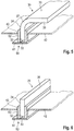
- FIG. 1 shows a cooking surface 10, which is preferably designed as a colored glass ceramic. It has an upper side 11 and a lower side 12.
- a coating 13 is applied to the cooking surface 10, which prevents viewing of the components arranged in the area behind the underside 12 of the cooking surface.
- the coating 13 has partial interruptions 14 which serve as light passages. This forms the Coating 13 a mask.
- the cooking surface 10 is formed from a transparent glass material or a glass ceramic. It can be colored in order to achieve a corresponding aesthetic look. The coloring can also be selected in such a way that a view through the glass ceramic is essentially prevented.
- the rear coating 13 can then be dispensed with. Heating elements 20 are arranged in the area behind the underside 12 of the cooking surface 10.
- a heating element 20 having an induction coil 21 is shown as an example.
- the heating element 20 is mounted on a support section 42 of a pressing device 40.
- the support section 42 is supported on a housing 50 via spring elements 41.
- the support section 42 is supported with respect to a housing bottom 51 of the housing 50 by means of the spring elements 41.
- Light elements 30 are also mounted on the support section 42.
- the lighting elements 30 are arranged in such a way that a spacing area is formed between the underside 12 of the cooking surface 10 and the lighting element 30.
- the distance is preferably selected in the range between 0.2 to 10 mm, preferably in the range from 0.5 to 5 mm, in particular in the range between 0.5 and 2 mm.
- the lighting elements 30 are positioned in such a way that their emission area 36 is arranged in the area of the interruption 14 of the coating 13. While the left luminous element 30 enters its luminous appearance directly into the cooking surface 10 via the radiation area 36, an optical compensation filter and / or an immersion layer 31 is arranged on the right luminous element 30 between the underside 12 of the cooking surface 10 and the lighting element 30.
- the luminous appearance of the luminous element 30 can be changed with the optical compensation filter or the immersion layer 31.
- the cooking surface 10 is elastically glued at the edge into a frame or glued with mounting brackets that are screwed, latched or the like. Connected to the housing 50. The assignment is made in such a way that the cooking surface 10 is supported in a resilient manner with respect to the housing 50. If now a shock load acts on the top 11 of the cooking surface 10, the Bend the cooking surface and can oscillate in relation to the housing. During this transient process, the heating element 20, which is pressed against the underside 13 of the cooking surface 10, is also deflected. Since the luminous elements 30 are positioned in a fixed assignment to the heating element 20 on the support section 42, they swing back together with the heating element 20 against the bias of the springs 41.
- the support section 42 is adjusted against the spring elements 41 in the direction of the housing depth. As a result of the spacing of the lighting elements 30 relative to the underside 13 of the cooking surface 10 and with the deflectable support section 42, the underside 13 is reliably prevented from hitting the lighting elements 30. Damage to the light-emitting elements 30 can thus be practically ruled out.
- the support section 42 itself can have a spring effect. In this case there is no need to use additional springs.
- FIG 2 an exemplary embodiment for fixing the luminous element 30 to the support section 42 is shown.
- a holder 60 is used here, which has a fastening piece 61, which can be designed, for example, in the form of a printed circuit board.
- a holding lug 62 is attached to the fastening piece 61.
- the fastening piece 61 carries a lighting means 33 of the luminous element 30.
- the fastening piece 61 is equipped with a contact area which maintains an electrical contact for the voltage supply of the luminous element 30 in the area of the underside of the support section 42.
- the support section 42 is provided with an opening 43 through which the fastening piece 61 extends.
- a connection 63 is provided to fix the holder 60 on the support section 42.
- the support section 42 can consist of a sheet metal.
- the connection 63 can be, for example, a weld, screw connection or adhesive bond, with which the retaining lug 62 is connected to the surface of the support section 42.
- the holding attachment 62 forms a receptacle into which a light guide of the luminous element 30 can be inserted.
- the light guide has a coupling piece 32 which is inserted into the holding attachment 62.
- a light guide section 34 adjoins the coupling piece 32.
- the light guide section 34 of the Luminous element 30 formed from a rod-shaped material with a circular cross-section.
- the luminous element 30 can be a glass rod.
- the light source 33 couples its light into the coupling piece 32 at the end, from there the light reaches the area of the light guide section 34.
- the light element 30 has its emission area 36 in the area facing the underside 13 of the cooking surface 10.
- the light of the illuminant 33 is coupled out of the light guide section 34.
- the decoupling can be carried out, for example, by means of suitable measures, for example etching the surface of the light guide section 34. It is also conceivable to provide scattered light structures on the upper side of the light guide section 34. It is also provided that the light is coupled out via a scattering reflective layer on the side of the light guide 30 facing away from the underside of the cooking surface.
- the scattering reflective layer can be produced by a scattering film or roughening of the light guide surface or printing in the desired partial area of the light guide.
- Figure 3 shows two different variants of a holder 60 for fixing a lighting element 30. While the fastening piece 61 of the left holder 60 protrudes significantly above the holding attachment 62, a flattening 64 is provided on the fastening piece 61 on the right holder 60, so that the holding attachment 62 is preferably flush with the The top of the fastening piece 61 closes off or is only at a short distance from the top of the fastening piece 61. With the in Figure 3 The variant of a holder 60 shown on the right, the distance between the underside 12 of the cooking surface 10 and the lighting element 30 can be reduced in favor of an improved light yield.
- FIG. 4 shows a further variant of a holder 60.
- the basic construction of the holder is again similar to that of FIGS Figures 2 and 3 elected.
- the holder 60 again has a fastening piece 61 with a holding attachment 62 connected.
- the support section 42 has a fold in the area of which the connection 63 to the retaining lug 62 can be realized.
- a light guide of the lighting element 30 in the form of a curved glass rod, Plastic rod or a rod made of another transparent material used.
- the light guide has two light guide sections 34, 35 which are arranged at an angle to one another and which are merged into one another in one piece via an arcuate bend 37.
- the lighting means 33 in particular can be held below the support section 42, as a result of which an additional distance from the heating element and thermal insulation is achieved. As a result, the service life of the lighting means 33 can be increased.
- Figure 5 is basically a similar structure as in Figure 4 shown.
- No rod-shaped light guide is used here, but a light guide in the form of an angled plate, for example made of glass or plastic.
- Two light guide sections 34, 35 are again passed into one another via an angled portion 37.
- the light guide section 35 forms on its upper side an emission area 36 in the form of a rectangular or square area, which can also be structured, depending on the intended scattering or reflection areas.
- Figure 6 shows a light guide of a luminous element 30 in the form of a flat plate, which is set with its coupling piece 32 in the holder 60.
- the plate forms a radiation area 36 via which the light coupled in by the illuminant is emitted.
- the holder is also designed with a correspondingly elongated holding projection 62.
- the holding attachment is formed by two flat elements spaced parallel to one another and between which the coupling piece 32 is enclosed.
- a plurality of illuminants are preferably arranged next to one another in the direction of the longitudinal extension of the holding projection 62.
- the lighting means 33 are preferably arranged at the same spacing from one another in order to be able to achieve uniform illumination.
- the equalization of the illumination can be improved by attaching it a scattering surface on the surface of the light guide facing the illuminant.
- the scattering surface can be made by roughening or printing or, particularly advantageously, by using a special adhesive tape, which is offered by the 3M company as unifomity tape.
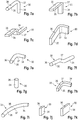
- FIGS. 7a to 7i show various embodiments of rod-shaped light guides of a luminous element 30, always using two light guide sections 34, 35 which are at an angle to one another and which are connected to one another in one piece via an angled portion 37.
- a circular cross-section is selected which enables light to be coupled out via the scattering or reflection area on the side of the light guide facing away from the cooking surface.
- a light guide with a rectangular or square cross-section is selected for this purpose.
- Figure 7c shows a similar cross-sectional configuration of the light guide.
- the bend 37 is selected so that the light guide sections 34, 35 are at a small angle to one another. But they can also be arranged parallel to one another.
- a rectangular cross section is selected for the light guide, the height of the light guide being significantly greater than the width of the light guide.
- Figure 7e shows an embodiment of a light guide accordingly Figure 4 .
- Figure 7f shows a similar configuration of a light guide to FIG Figure 7c only with a round rod cross-section.
- Figure 7g shows a variant of a cylindrical light guide.
- Figure 7h shows a light guide similar to Figure 7d is designed, but has a lower height.
- 7i shows a light guide with an arcuate course.
- FIGS. 7I and 7m show light guides of a luminous element 30 analogous to the exemplary embodiment according to FIG Figure 5 . These representations show that for Variation of the geometry of the emitting surface can vary both the extension of the light guide in depth and in width directions.
- Figure 7q shows again, similar to Figure 5 , a plate-shaped light guide, the light guide section 35 having a concave geometry 30.1 at its free end in order to be able to visualize an arcuate geometry, for example the terminating area of a heating element 20.
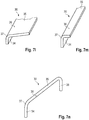
- Figure 7r shows a light guide which is formed by a plate-shaped blank and has two leg-like light guide sections 34 and 38 which merge into the light guide section 35 via bends 37.
- the light guide section 35 forms a large-area emission surface 36.
- Figure 7s discloses a light guide which has two plate-like light guide sections 34, 35 which merge into one another via an angled 37.
- the light guide sections 34, 35 are set at a small angle to one another or are preferably arranged parallel to one another.
- Figure 7t discloses a variant similar to Figure 7r however, a smaller width of the light guide section 35 is selected so that a correspondingly narrower radiating surface 36 results.
- Figure 7u shows an embodiment of a light guide which has plate-like light guide sections 34, 35 and 38 which merge into one another via the bends 37.
- the light guide sections 34, 38 are preferably parallel to one another aligned.
- the light guide section 35 is provided with an opening 30.2, which preferably has a circular design corresponding to the geometry of the heating element 20.
- the opening 30.2 is limited by the geometric edge 30.1.
- the emission regions 36 are preferably arranged parallel to the underside 12 of the cooking surface 10.
- the radiating surfaces 36 can also be at an angle to the underside 12 of the cooking surface 10.
- Figure 8 discloses an embodiment of a luminous element 30 with a two-part shape of the light guide.
- a light guide element in angular geometry is formed in one piece by the two light guide sections 34 and 35 or the angled portion 37.
- the light guide section 34 is correspondingly for example Figure 2 attached to a holder 60.
- the light guide section 35 is now inserted in a holder 70.
- the holder 70 carries a light guide section 38 designed as a rod profile.
- the light guide sections 35 and 38 are positioned in the holder 70 such that the light of the luminous element 33 coming from the light guide section 35 can be coupled into the light guide section 38.
- FIG. 9a to 9e different design variants of the invention are shown.
- a circular heating element 22 is symbolized in these representations, to which the emission regions 36 of luminous elements 30 are assigned.
- Figure 9a shows using the light guide Figure 7i four arcuate radiating areas 36 which enclose the heating element 20.
- Figure 9b also shows using the light guide Figure 7i two arcuate radiating areas 36 which enclose the heating element 20.
- Figure 9c shows four line-shaped radiation regions 36 which enclose the heating element 20, the light guides according to FIG Figure 7k come into use.
- Figure 9d shows four point-shaped emission areas 36 of lighting means 33 using the light guide according to FIG Figure 7g are designed.
- an emission region 36 is shown which is produced using the light guide according to FIG Figure 7u can be designed.
- Figures 10a to 10c illustrate that a plurality of heating elements 20 can be installed on a support section 42.
- Different radiation areas 36 can be assigned to the support section 42 in order to be able to either optically mark the delimitation of the support section 42 and / or to be able to optically delimit individual heating elements 20.
- Figure 10a shows, not only circular heating elements 20 in plan view, but rather any other geometries of heating elements 20, for example oval heating elements 20, can be used.
- Figure 10c shows that several rows of heating elements 20 can be installed on a support section 42.
- Figure 10d shows the rectangular configuration of a heating element 20 mounted on a support section 42
- Figure 10a are light guides according to Figure 7h or 7e , at Figure 10b according to Figure 7k or Figure 2 , at Figure 10c according to Figure 7k or Figure 2 and at Figure 10c according to Figure 7m used.
- Figure 10e a light guide, in which a plurality of openings 30.2 can also be made in the light guide section 35.
- Figure 11 shows a cooking appliance for a surface induction application, wherein a plurality of induction coils 21 of heating elements 20 are mounted on a support section 42.
- Figure 12 shows, between the induction coils 21 luminous elements with light guides according to Figure 7g be arranged.
- Figure 13 also a line-shaped marking of the induction coils 21 with lighting means, having light guides, for example according to FIGS Figures 7j and 7k be used.
- Figure 14 shows a disk-like carrier 22. This takes, like the Figures 14a and 14b show an induction coil 21. Projections which form receptacles 23 are formed on the carrier 22. Luminous means 33 are inserted into the receptacles 23, which directly have a radiating surface 36 to form a luminous element 30 and can be designed as LEDs, for example (see FIG Figure 14b ). Alternatively, the light elements 30 according to Figure 14a also a light guide, for example, according to Figure 7g have, then in the receptacle 23 a Illuminant 33, for example an LED, is installed.
- the carrier 22 can form the support section 42 on which the spring elements 41 are supported.
- the supports 22 are preferably arranged in rows, the supports 22 of a row being particularly preferably mounted on a common support section 42 in the form of, for example, a cross member.
- Figure 15 symbolizes such a row-like arrangement of the supports 22 and thus of the heating elements 20. Accordingly, in Figure 15 three (or more) juxtaposed support sections 42 are used, which are then each connected to the housing 50 of the cooking appliance. As the Figures 15 and 14th show, the receptacles 23 or the luminous elements 30 are arranged distributed over the circumference of the carrier 22 at the same angular distance ⁇ from one another. Preferably, three receptacles 23 are provided, which are arranged offset from one another by 120 °. In this way, how Figure 15 shows, achieve a compact assignment of the individual heating elements 20 to one another and a uniform illumination of the intermediate areas between the carriers 22 is made possible.
- the Figures 16 and 17 show the cooking appliance according to FIG Fig. 1 in a modified version, with a light-scattering element 70, in particular a light-scattering plane in the form of a roughening, organic or ceramic coating, a scattering film, a scattering glass or ceramic plate or a scattering plastic film on the underside 12 of the cooking surface 19 to improve the light appearance may be appropriate.
- the indirect carrier of the light-scattering layer can either be with an adhesive layer or self-adhesive or loosely connected to the underside 12 via pressure forces.
- the light-scattering plane causes the viewing angle ⁇ 1, ⁇ 2 to be widened and the parallax shift to be reduced whereby the recognition of this luminous phenomenon for the user B is significantly improved.
Landscapes
- Engineering & Computer Science (AREA)
- Chemical & Material Sciences (AREA)
- Combustion & Propulsion (AREA)
- Mechanical Engineering (AREA)
- General Engineering & Computer Science (AREA)
- Ceramic Engineering (AREA)
- Physics & Mathematics (AREA)
- Electromagnetism (AREA)
- Induction Heating Cooking Devices (AREA)
- Electric Stoves And Ranges (AREA)
Priority Applications (2)
| Application Number | Priority Date | Filing Date | Title |
|---|---|---|---|
| EP17203551.1A EP3321592A1 (de) | 2013-07-16 | 2014-05-07 | Kochgerät mit lichtelementen |
| PL14167301T PL2827064T3 (pl) | 2013-07-16 | 2014-05-07 | Urządzenie do gotowania z elementami świetlnymi |
Applications Claiming Priority (2)
| Application Number | Priority Date | Filing Date | Title |
|---|---|---|---|
| DE102013107523 | 2013-07-16 | ||
| DE102013110277.8A DE102013110277B4 (de) | 2013-07-16 | 2013-09-18 | Kochgerät mit Lichtelementen |
Related Child Applications (2)
| Application Number | Title | Priority Date | Filing Date |
|---|---|---|---|
| EP17203551.1A Division EP3321592A1 (de) | 2013-07-16 | 2014-05-07 | Kochgerät mit lichtelementen |
| EP17203551.1A Division-Into EP3321592A1 (de) | 2013-07-16 | 2014-05-07 | Kochgerät mit lichtelementen |
Publications (2)
| Publication Number | Publication Date |
|---|---|
| EP2827064A1 EP2827064A1 (de) | 2015-01-21 |
| EP2827064B1 true EP2827064B1 (de) | 2021-06-02 |
Family
ID=50639354
Family Applications (2)
| Application Number | Title | Priority Date | Filing Date |
|---|---|---|---|
| EP14167301.2A Active EP2827064B1 (de) | 2013-07-16 | 2014-05-07 | Kochgerät mit Lichtelementen |
| EP17203551.1A Withdrawn EP3321592A1 (de) | 2013-07-16 | 2014-05-07 | Kochgerät mit lichtelementen |
Family Applications After (1)
| Application Number | Title | Priority Date | Filing Date |
|---|---|---|---|
| EP17203551.1A Withdrawn EP3321592A1 (de) | 2013-07-16 | 2014-05-07 | Kochgerät mit lichtelementen |
Country Status (6)
| Country | Link |
|---|---|
| US (1) | US10228146B2 (pl) |
| EP (2) | EP2827064B1 (pl) |
| JP (1) | JP6621976B2 (pl) |
| CN (2) | CN110500622A (pl) |
| ES (1) | ES2880299T3 (pl) |
| PL (1) | PL2827064T3 (pl) |
Families Citing this family (14)
| Publication number | Priority date | Publication date | Assignee | Title |
|---|---|---|---|---|
| EP3031785B1 (de) * | 2014-12-12 | 2018-10-17 | Schott AG | Verfahren zur herstellung eines glaskeramikelements mit strukturierter beschichtung |
| US10314427B2 (en) | 2015-07-27 | 2019-06-11 | Whirlpool Corporation | Light guide for generating illuminated indicia for an electric burner of a heating appliance |
| US10314428B2 (en) | 2015-07-27 | 2019-06-11 | Whirlpool Corporation | Fiber optic light guide for generating illuminated indicia for an electric burner of a heating appliance |
| WO2017108356A1 (en) * | 2015-12-25 | 2017-06-29 | Arcelik Anonim Sirketi | An induction heating cooker comprising a light source |
| CN105744665B (zh) * | 2016-03-28 | 2019-01-25 | 邢昱 | 振动式电磁炉 |
| KR102493148B1 (ko) * | 2016-03-28 | 2023-01-27 | 엘지전자 주식회사 | 테이블 |
| KR102493915B1 (ko) * | 2016-06-03 | 2023-02-01 | 삼성전자주식회사 | 오븐 |
| DE102018216818B4 (de) | 2018-09-28 | 2020-04-16 | Schott Ag | Arbeitsplatte sowie ein Arbeitstisch umfassend eine Arbeitsplatte |
| EP3672363B1 (en) * | 2018-12-17 | 2021-05-05 | Electrolux Appliances Aktiebolag | Induction cooking hob with illumination equipment |
| JP7241578B2 (ja) * | 2019-03-15 | 2023-03-17 | リンナイ株式会社 | 液晶表示装置及びこれを備えた加熱調理器 |
| US12410919B2 (en) | 2019-09-06 | 2025-09-09 | BSH Hausgeräte GmbH | Cooktop device |
| DE102019217915A1 (de) * | 2019-11-20 | 2021-05-20 | BSH Hausgeräte GmbH | Dunstabzugsvorrichtung mit Wrasenleitplatte und Beleuchtungseinrichtung |
| CN112361400B (zh) * | 2020-09-28 | 2026-03-17 | 华帝股份有限公司 | 一种具有氛围灯的吸油烟机 |
| US11982447B2 (en) | 2021-11-29 | 2024-05-14 | Haier Us Appliance Solutions, Inc. | Appliance control panel lighting system |
Citations (2)
| Publication number | Priority date | Publication date | Assignee | Title |
|---|---|---|---|---|
| JP2003151746A (ja) * | 2001-11-13 | 2003-05-23 | Matsushita Electric Ind Co Ltd | 誘導加熱調理器 |
| EP2410815A1 (en) * | 2009-03-19 | 2012-01-25 | Panasonic Corporation | Induction heating cooker |
Family Cites Families (33)
| Publication number | Priority date | Publication date | Assignee | Title |
|---|---|---|---|---|
| DE3613902A1 (de) | 1986-04-24 | 1987-10-29 | Ego Elektro Blanc & Fischer | Kochplatte, insbesondere fuer grosskuechen-herde |
| DE3831233A1 (de) | 1988-09-14 | 1990-03-22 | Ego Elektro Blanc & Fischer | Heizkoerper |
| DE3835735A1 (de) | 1988-10-20 | 1990-04-26 | Ako Werke Gmbh & Co | Anzeigeeinrichtung eines kochfeldes |
| DE4002322A1 (de) | 1990-01-26 | 1991-08-01 | Bosch Siemens Hausgeraete | Kochfeld |
| DE4004309A1 (de) | 1990-02-13 | 1991-08-14 | Ego Elektro Blanc & Fischer | Anzeigeeinrichtung fuer kochgeraete |
| DE4105627A1 (de) | 1991-02-22 | 1992-08-27 | Mmg Minnahuette Masch Glas | Leuchtring zur kennzeichnung des kochfeldes bei glaskeramikabdeckungen an elektroherden |
| GB2271840B (en) | 1992-10-24 | 1996-02-21 | Zortech Int | Optical indicating arrangement |
| DE9302894U1 (de) | 1993-02-27 | 1993-04-15 | Pistor + Boss GmbH, 5880 Lüdenscheid | Elektrische Leuchte zur Anzeige der Wärme oder Restwärme an elektrischen Kochplatten |
| DE19651859C1 (de) * | 1996-12-13 | 1997-12-04 | Schott Glaswerke | Befestigungsvorrichtung für als Kochzonenmarkierung und/oder Restwärmeanzeige dienende Lichtleiter |
| DE10004446B4 (de) * | 2000-02-03 | 2004-05-06 | E.G.O. Elektro-Gerätebau GmbH | Beleuchtungseinrichtung für eine Heizeinrichtung |
| US6300602B1 (en) * | 2000-05-26 | 2001-10-09 | Bsh Home Appliances Corporation | Light ring display for cooktop |
| JP3769462B2 (ja) | 2000-12-08 | 2006-04-26 | 株式会社東芝 | 加熱調理器 |
| US6969834B2 (en) * | 2001-07-03 | 2005-11-29 | Matsushita Electric Industrial Co., Ltd. | Line type luminous device and induction heating cooker employing same |
| WO2003098115A1 (fr) * | 2002-05-16 | 2003-11-27 | Nippon Electric Glass Co., Ltd. | Plaque de cuisson superieure |
| JP4133408B2 (ja) * | 2003-02-14 | 2008-08-13 | 株式会社東芝 | 誘導加熱調理器 |
| JP4444199B2 (ja) | 2005-11-16 | 2010-03-31 | パナソニック株式会社 | 加熱調理器 |
| DE102006027739B4 (de) | 2006-06-16 | 2008-05-29 | Schott Ag | Kochfeld mit einer Glaskeramikplatte als Kochfläche |
| CN101627661B (zh) * | 2007-03-12 | 2012-05-23 | 松下电器产业株式会社 | 感应加热烹饪器 |
| CN101622905B (zh) * | 2007-08-13 | 2012-06-20 | 松下电器产业株式会社 | 感应加热烹调器 |
| EP2288231B1 (en) * | 2008-05-27 | 2018-08-08 | Panasonic Corporation | Induction heating cooking apparatus |
| DE102008050263C5 (de) | 2008-10-07 | 2020-01-02 | Schott Ag | Transparente, eingefärbte Kochfläche mit verbesserter farbiger Anzeigefähigkeit und Verfahren zur Herstellung einer solchen Kochfläche |
| JP5169970B2 (ja) | 2009-04-21 | 2013-03-27 | パナソニック株式会社 | 誘導加熱調理器 |
| WO2011010428A1 (ja) | 2009-07-24 | 2011-01-27 | パナソニック株式会社 | 加熱調理器 |
| WO2011020720A1 (de) * | 2009-08-17 | 2011-02-24 | BSH Bosch und Siemens Hausgeräte GmbH | Induktiv beheiztes kochfeld mit einer metallisch beschichteten abdeckplatte |
| JP5671470B2 (ja) * | 2009-10-23 | 2015-02-18 | パナソニックIpマネジメント株式会社 | 誘導加熱装置 |
| DE102010032112A1 (de) * | 2010-07-23 | 2012-01-26 | Schott Ag | Glaskeramik als Kochfläche für Induktionsbeheizung mit verbesserter farbiger Anzeigefähigkeit und Wärmeabschirmung, Verfahren zur Herstellung einer solchen Kochfläche und ihre Verwendung |
| FR2967236B1 (fr) * | 2010-11-04 | 2014-10-10 | Eurokera | Article vitroceramique lumineux |
| DE202010013087U1 (de) | 2010-12-08 | 2011-02-24 | Schott Ag | Anzeige |
| DE102010061123A1 (de) * | 2010-12-08 | 2012-06-14 | Schott Ag | Anzeige |
| JP5682432B2 (ja) | 2011-04-15 | 2015-03-11 | パナソニックIpマネジメント株式会社 | 加熱調理器用のトッププレート |
| DE202011110029U1 (de) | 2011-06-06 | 2012-10-08 | Schott Ag | Anzeigevorrichtung |
| DE102011115379B4 (de) * | 2011-10-10 | 2018-09-27 | Schott Ag | Beschichtetes Glas- oder Glaskeramik-Substrat mit haptischen Eigenschaften und Glaskeramik-Kochfeld |
| US9109803B2 (en) * | 2012-02-28 | 2015-08-18 | General Electric Company | Cooktop appliance with features for improving illumination |
-
2014
- 2014-05-07 ES ES14167301T patent/ES2880299T3/es active Active
- 2014-05-07 EP EP14167301.2A patent/EP2827064B1/de active Active
- 2014-05-07 PL PL14167301T patent/PL2827064T3/pl unknown
- 2014-05-07 EP EP17203551.1A patent/EP3321592A1/de not_active Withdrawn
- 2014-07-15 CN CN201910676786.1A patent/CN110500622A/zh active Pending
- 2014-07-15 CN CN201410336502.1A patent/CN104296200A/zh active Pending
- 2014-07-16 JP JP2014145870A patent/JP6621976B2/ja active Active
- 2014-07-16 US US14/332,432 patent/US10228146B2/en not_active Expired - Fee Related
Patent Citations (2)
| Publication number | Priority date | Publication date | Assignee | Title |
|---|---|---|---|---|
| JP2003151746A (ja) * | 2001-11-13 | 2003-05-23 | Matsushita Electric Ind Co Ltd | 誘導加熱調理器 |
| EP2410815A1 (en) * | 2009-03-19 | 2012-01-25 | Panasonic Corporation | Induction heating cooker |
Also Published As
| Publication number | Publication date |
|---|---|
| EP3321592A1 (de) | 2018-05-16 |
| EP2827064A1 (de) | 2015-01-21 |
| CN110500622A (zh) | 2019-11-26 |
| PL2827064T3 (pl) | 2021-11-22 |
| ES2880299T3 (es) | 2021-11-24 |
| JP2015023028A (ja) | 2015-02-02 |
| US20150021312A1 (en) | 2015-01-22 |
| JP6621976B2 (ja) | 2019-12-18 |
| CN104296200A (zh) | 2015-01-21 |
| US10228146B2 (en) | 2019-03-12 |
Similar Documents
| Publication | Publication Date | Title |
|---|---|---|
| EP2827064B1 (de) | Kochgerät mit Lichtelementen | |
| DE102009033538A1 (de) | Bedieneinrichtung für ein Elektrogerät | |
| DE202012003287U1 (de) | Kochfeld mit einer Platte und einem Leuchtmittel | |
| DE102009002775A1 (de) | Lampe für Hausgerät sowie Hausgerät, insbesondere zum Zubereiten von Lebensmitteln, mit einer Lampe | |
| DE202013103165U1 (de) | Kochgerät mit Lichtelementen | |
| DE112013004163T5 (de) | Induktionsheizeinrichtung | |
| DE102018207071B4 (de) | Bedien- und/oder Anzeigeelement für ein Kraftfahrzeug | |
| DE102013110277B4 (de) | Kochgerät mit Lichtelementen | |
| EP2602553A1 (de) | Haushaltsgerätetür mit Beleuchtungseinrichtung | |
| DE19902489B4 (de) | Duschkombination | |
| EP2913736B1 (de) | Drehwahleinrichtung für ein haushaltsgerät mit beleuchtetem drehknebel | |
| EP2462070A1 (de) | Hausgeräte-abdeckplatte mit einer laser-innengravur | |
| EP2223565B1 (de) | Kochfeld | |
| EP3653020A1 (de) | Kochfeldvorrichtung | |
| EP2267358A2 (de) | Beleuchtungseinrichtung für den Behandlungsraum von Hausgeräten | |
| WO2016185301A1 (de) | Kochfeldvorrichtung und verfahren mit einer kochfeldvorrichtung | |
| DE102016200569A1 (de) | Anzeigeeinrichtung für ein Elektrogerät, Elektrogerät und Verfahren zur Herstellung einer solchen Anzeigeeinrichtung | |
| DE102017223289B4 (de) | Beleuchtungseinrichtung für ein Kochgerät und Kochgerät mit einer Beleuchtungseinrichtung | |
| EP3738411B1 (de) | Kochfeldvorrichtung | |
| DE102016213004A1 (de) | Bedienmodul für ein Kochfeld | |
| EP1929840A1 (de) | Halteanordnung für eine kochfeldplatte eines gargerätes | |
| EP4098080B1 (de) | Kochfeldvorrichtung | |
| DE9316042U1 (de) | Optische Anzeigevorrichtung | |
| EP1982116A2 (de) | Gargerät, insbesondere hocheinbau-gargerät, und verfahren zu dessen herstellung | |
| BE1031423B1 (de) | Kochfeldeinrichtung |
Legal Events
| Date | Code | Title | Description |
|---|---|---|---|
| 17P | Request for examination filed |
Effective date: 20140507 |
|
| AK | Designated contracting states |
Kind code of ref document: A1 Designated state(s): AL AT BE BG CH CY CZ DE DK EE ES FI FR GB GR HR HU IE IS IT LI LT LU LV MC MK MT NL NO PL PT RO RS SE SI SK SM TR |
|
| AX | Request for extension of the european patent |
Extension state: BA ME |
|
| PUAI | Public reference made under article 153(3) epc to a published international application that has entered the european phase |
Free format text: ORIGINAL CODE: 0009012 |
|
| R17P | Request for examination filed (corrected) |
Effective date: 20150721 |
|
| RBV | Designated contracting states (corrected) |
Designated state(s): AL AT BE BG CH CY CZ DE DK EE ES FI FR GB GR HR HU IE IS IT LI LT LU LV MC MK MT NL NO PL PT RO RS SE SI SK SM TR |
|
| STAA | Information on the status of an ep patent application or granted ep patent |
Free format text: STATUS: EXAMINATION IS IN PROGRESS |
|
| 17Q | First examination report despatched |
Effective date: 20170206 |
|
| REG | Reference to a national code |
Ref country code: DE Ref legal event code: R079 Free format text: PREVIOUS MAIN CLASS: F24C0007060000 Ipc: F24C0007080000 |
|
| RIC1 | Information provided on ipc code assigned before grant |
Ipc: H05B 6/12 20060101ALI20201127BHEP Ipc: F24C 7/06 20060101ALI20201127BHEP Ipc: H05B 3/74 20060101ALI20201127BHEP Ipc: F24C 15/10 20060101ALI20201127BHEP Ipc: F24C 7/08 20060101AFI20201127BHEP |
|
| GRAP | Despatch of communication of intention to grant a patent |
Free format text: ORIGINAL CODE: EPIDOSNIGR1 |
|
| STAA | Information on the status of an ep patent application or granted ep patent |
Free format text: STATUS: GRANT OF PATENT IS INTENDED |
|
| RAP1 | Party data changed (applicant data changed or rights of an application transferred) |
Owner name: SCHOTT AG |
|
| INTG | Intention to grant announced |
Effective date: 20210119 |
|
| GRAS | Grant fee paid |
Free format text: ORIGINAL CODE: EPIDOSNIGR3 |
|
| GRAA | (expected) grant |
Free format text: ORIGINAL CODE: 0009210 |
|
| STAA | Information on the status of an ep patent application or granted ep patent |
Free format text: STATUS: THE PATENT HAS BEEN GRANTED |
|
| RBV | Designated contracting states (corrected) |
Designated state(s): AL AT BE BG CH CY CZ DK EE ES FI FR GB GR HR HU IE IS IT LI LT LU LV MC MK MT NL NO PL PT RO RS SE SI SK SM TR |
|
| REG | Reference to a national code |
Ref country code: DE Ref legal event code: R108 |
|
| REG | Reference to a national code |
Ref country code: CH Ref legal event code: EP |
|
| AK | Designated contracting states |
Kind code of ref document: B1 Designated state(s): AL AT BE BG CH CY CZ DK EE ES FI FR GB GR HR HU IE IS IT LI LT LU LV MC MK MT NL NO PL PT RO RS SE SI SK SM TR |
|
| REG | Reference to a national code |
Ref country code: GB Ref legal event code: FG4D Free format text: NOT ENGLISH |
|
| REG | Reference to a national code |
Ref country code: AT Ref legal event code: REF Ref document number: 1398803 Country of ref document: AT Kind code of ref document: T Effective date: 20210615 |
|
| REG | Reference to a national code |
Ref country code: IE Ref legal event code: FG4D Free format text: LANGUAGE OF EP DOCUMENT: GERMAN |
|
| REG | Reference to a national code |
Ref country code: LT Ref legal event code: MG9D |
|
| PG25 | Lapsed in a contracting state [announced via postgrant information from national office to epo] |
Ref country code: FI Free format text: LAPSE BECAUSE OF FAILURE TO SUBMIT A TRANSLATION OF THE DESCRIPTION OR TO PAY THE FEE WITHIN THE PRESCRIBED TIME-LIMIT Effective date: 20210602 Ref country code: LT Free format text: LAPSE BECAUSE OF FAILURE TO SUBMIT A TRANSLATION OF THE DESCRIPTION OR TO PAY THE FEE WITHIN THE PRESCRIBED TIME-LIMIT Effective date: 20210602 Ref country code: BG Free format text: LAPSE BECAUSE OF FAILURE TO SUBMIT A TRANSLATION OF THE DESCRIPTION OR TO PAY THE FEE WITHIN THE PRESCRIBED TIME-LIMIT Effective date: 20210902 Ref country code: HR Free format text: LAPSE BECAUSE OF FAILURE TO SUBMIT A TRANSLATION OF THE DESCRIPTION OR TO PAY THE FEE WITHIN THE PRESCRIBED TIME-LIMIT Effective date: 20210602 |
|
| REG | Reference to a national code |
Ref country code: NL Ref legal event code: MP Effective date: 20210602 |
|
| REG | Reference to a national code |
Ref country code: ES Ref legal event code: FG2A Ref document number: 2880299 Country of ref document: ES Kind code of ref document: T3 Effective date: 20211124 |
|
| PG25 | Lapsed in a contracting state [announced via postgrant information from national office to epo] |
Ref country code: LV Free format text: LAPSE BECAUSE OF FAILURE TO SUBMIT A TRANSLATION OF THE DESCRIPTION OR TO PAY THE FEE WITHIN THE PRESCRIBED TIME-LIMIT Effective date: 20210602 Ref country code: GR Free format text: LAPSE BECAUSE OF FAILURE TO SUBMIT A TRANSLATION OF THE DESCRIPTION OR TO PAY THE FEE WITHIN THE PRESCRIBED TIME-LIMIT Effective date: 20210903 Ref country code: RS Free format text: LAPSE BECAUSE OF FAILURE TO SUBMIT A TRANSLATION OF THE DESCRIPTION OR TO PAY THE FEE WITHIN THE PRESCRIBED TIME-LIMIT Effective date: 20210602 Ref country code: SE Free format text: LAPSE BECAUSE OF FAILURE TO SUBMIT A TRANSLATION OF THE DESCRIPTION OR TO PAY THE FEE WITHIN THE PRESCRIBED TIME-LIMIT Effective date: 20210602 Ref country code: NO Free format text: LAPSE BECAUSE OF FAILURE TO SUBMIT A TRANSLATION OF THE DESCRIPTION OR TO PAY THE FEE WITHIN THE PRESCRIBED TIME-LIMIT Effective date: 20210902 |
|
| PG25 | Lapsed in a contracting state [announced via postgrant information from national office to epo] |
Ref country code: SK Free format text: LAPSE BECAUSE OF FAILURE TO SUBMIT A TRANSLATION OF THE DESCRIPTION OR TO PAY THE FEE WITHIN THE PRESCRIBED TIME-LIMIT Effective date: 20210602 Ref country code: SM Free format text: LAPSE BECAUSE OF FAILURE TO SUBMIT A TRANSLATION OF THE DESCRIPTION OR TO PAY THE FEE WITHIN THE PRESCRIBED TIME-LIMIT Effective date: 20210602 Ref country code: EE Free format text: LAPSE BECAUSE OF FAILURE TO SUBMIT A TRANSLATION OF THE DESCRIPTION OR TO PAY THE FEE WITHIN THE PRESCRIBED TIME-LIMIT Effective date: 20210602 Ref country code: CZ Free format text: LAPSE BECAUSE OF FAILURE TO SUBMIT A TRANSLATION OF THE DESCRIPTION OR TO PAY THE FEE WITHIN THE PRESCRIBED TIME-LIMIT Effective date: 20210602 Ref country code: RO Free format text: LAPSE BECAUSE OF FAILURE TO SUBMIT A TRANSLATION OF THE DESCRIPTION OR TO PAY THE FEE WITHIN THE PRESCRIBED TIME-LIMIT Effective date: 20210602 Ref country code: PT Free format text: LAPSE BECAUSE OF FAILURE TO SUBMIT A TRANSLATION OF THE DESCRIPTION OR TO PAY THE FEE WITHIN THE PRESCRIBED TIME-LIMIT Effective date: 20211004 Ref country code: NL Free format text: LAPSE BECAUSE OF FAILURE TO SUBMIT A TRANSLATION OF THE DESCRIPTION OR TO PAY THE FEE WITHIN THE PRESCRIBED TIME-LIMIT Effective date: 20210602 |
|
| PLBE | No opposition filed within time limit |
Free format text: ORIGINAL CODE: 0009261 |
|
| STAA | Information on the status of an ep patent application or granted ep patent |
Free format text: STATUS: NO OPPOSITION FILED WITHIN TIME LIMIT |
|
| PG25 | Lapsed in a contracting state [announced via postgrant information from national office to epo] |
Ref country code: DK Free format text: LAPSE BECAUSE OF FAILURE TO SUBMIT A TRANSLATION OF THE DESCRIPTION OR TO PAY THE FEE WITHIN THE PRESCRIBED TIME-LIMIT Effective date: 20210602 |
|
| 26N | No opposition filed |
Effective date: 20220303 |
|
| PG25 | Lapsed in a contracting state [announced via postgrant information from national office to epo] |
Ref country code: AL Free format text: LAPSE BECAUSE OF FAILURE TO SUBMIT A TRANSLATION OF THE DESCRIPTION OR TO PAY THE FEE WITHIN THE PRESCRIBED TIME-LIMIT Effective date: 20210602 |
|
| REG | Reference to a national code |
Ref country code: CH Ref legal event code: PL |
|
| REG | Reference to a national code |
Ref country code: BE Ref legal event code: MM Effective date: 20220531 |
|
| GBPC | Gb: european patent ceased through non-payment of renewal fee |
Effective date: 20220507 |
|
| PG25 | Lapsed in a contracting state [announced via postgrant information from national office to epo] |
Ref country code: MC Free format text: LAPSE BECAUSE OF FAILURE TO SUBMIT A TRANSLATION OF THE DESCRIPTION OR TO PAY THE FEE WITHIN THE PRESCRIBED TIME-LIMIT Effective date: 20210602 Ref country code: LU Free format text: LAPSE BECAUSE OF NON-PAYMENT OF DUE FEES Effective date: 20220507 Ref country code: LI Free format text: LAPSE BECAUSE OF NON-PAYMENT OF DUE FEES Effective date: 20220531 Ref country code: CH Free format text: LAPSE BECAUSE OF NON-PAYMENT OF DUE FEES Effective date: 20220531 |
|
| PG25 | Lapsed in a contracting state [announced via postgrant information from national office to epo] |
Ref country code: IE Free format text: LAPSE BECAUSE OF NON-PAYMENT OF DUE FEES Effective date: 20220507 |
|
| PG25 | Lapsed in a contracting state [announced via postgrant information from national office to epo] |
Ref country code: GB Free format text: LAPSE BECAUSE OF NON-PAYMENT OF DUE FEES Effective date: 20220507 Ref country code: BE Free format text: LAPSE BECAUSE OF NON-PAYMENT OF DUE FEES Effective date: 20220531 |
|
| P01 | Opt-out of the competence of the unified patent court (upc) registered |
Effective date: 20230516 |
|
| REG | Reference to a national code |
Ref country code: AT Ref legal event code: MM01 Ref document number: 1398803 Country of ref document: AT Kind code of ref document: T Effective date: 20220507 |
|
| PG25 | Lapsed in a contracting state [announced via postgrant information from national office to epo] |
Ref country code: AT Free format text: LAPSE BECAUSE OF NON-PAYMENT OF DUE FEES Effective date: 20220507 |
|
| PG25 | Lapsed in a contracting state [announced via postgrant information from national office to epo] |
Ref country code: HU Free format text: LAPSE BECAUSE OF FAILURE TO SUBMIT A TRANSLATION OF THE DESCRIPTION OR TO PAY THE FEE WITHIN THE PRESCRIBED TIME-LIMIT; INVALID AB INITIO Effective date: 20140507 |
|
| PG25 | Lapsed in a contracting state [announced via postgrant information from national office to epo] |
Ref country code: MK Free format text: LAPSE BECAUSE OF FAILURE TO SUBMIT A TRANSLATION OF THE DESCRIPTION OR TO PAY THE FEE WITHIN THE PRESCRIBED TIME-LIMIT Effective date: 20210602 Ref country code: CY Free format text: LAPSE BECAUSE OF FAILURE TO SUBMIT A TRANSLATION OF THE DESCRIPTION OR TO PAY THE FEE WITHIN THE PRESCRIBED TIME-LIMIT Effective date: 20210602 |
|
| PG25 | Lapsed in a contracting state [announced via postgrant information from national office to epo] |
Ref country code: MT Free format text: LAPSE BECAUSE OF FAILURE TO SUBMIT A TRANSLATION OF THE DESCRIPTION OR TO PAY THE FEE WITHIN THE PRESCRIBED TIME-LIMIT Effective date: 20210602 |
|
| PGFP | Annual fee paid to national office [announced via postgrant information from national office to epo] |
Ref country code: PL Payment date: 20250425 Year of fee payment: 12 |
|
| PGFP | Annual fee paid to national office [announced via postgrant information from national office to epo] |
Ref country code: ES Payment date: 20250627 Year of fee payment: 12 |
|
| PGFP | Annual fee paid to national office [announced via postgrant information from national office to epo] |
Ref country code: IT Payment date: 20250527 Year of fee payment: 12 |
|
| PGFP | Annual fee paid to national office [announced via postgrant information from national office to epo] |
Ref country code: FR Payment date: 20250528 Year of fee payment: 12 |
|
| PGFP | Annual fee paid to national office [announced via postgrant information from national office to epo] |
Ref country code: TR Payment date: 20250429 Year of fee payment: 12 |