EP2823973B1 - Luftreifen - Google Patents
Luftreifen Download PDFInfo
- Publication number
- EP2823973B1 EP2823973B1 EP13757531.2A EP13757531A EP2823973B1 EP 2823973 B1 EP2823973 B1 EP 2823973B1 EP 13757531 A EP13757531 A EP 13757531A EP 2823973 B1 EP2823973 B1 EP 2823973B1
- Authority
- EP
- European Patent Office
- Prior art keywords
- tire
- grooves
- groove
- bent
- blocks
- Prior art date
- Legal status (The legal status is an assumption and is not a legal conclusion. Google has not performed a legal analysis and makes no representation as to the accuracy of the status listed.)
- Not-in-force
Links
Images



Classifications
-
- B—PERFORMING OPERATIONS; TRANSPORTING
- B60—VEHICLES IN GENERAL
- B60C—VEHICLE TYRES; TYRE INFLATION; TYRE CHANGING; CONNECTING VALVES TO INFLATABLE ELASTIC BODIES IN GENERAL; DEVICES OR ARRANGEMENTS RELATED TO TYRES
- B60C11/00—Tyre tread bands; Tread patterns; Anti-skid inserts
- B60C11/03—Tread patterns
- B60C11/0306—Patterns comprising block rows or discontinuous ribs
-
- B—PERFORMING OPERATIONS; TRANSPORTING
- B60—VEHICLES IN GENERAL
- B60C—VEHICLE TYRES; TYRE INFLATION; TYRE CHANGING; CONNECTING VALVES TO INFLATABLE ELASTIC BODIES IN GENERAL; DEVICES OR ARRANGEMENTS RELATED TO TYRES
- B60C11/00—Tyre tread bands; Tread patterns; Anti-skid inserts
- B60C11/03—Tread patterns
- B60C11/0302—Tread patterns directional pattern, i.e. with main rolling direction
-
- B—PERFORMING OPERATIONS; TRANSPORTING
- B60—VEHICLES IN GENERAL
- B60C—VEHICLE TYRES; TYRE INFLATION; TYRE CHANGING; CONNECTING VALVES TO INFLATABLE ELASTIC BODIES IN GENERAL; DEVICES OR ARRANGEMENTS RELATED TO TYRES
- B60C11/00—Tyre tread bands; Tread patterns; Anti-skid inserts
- B60C11/03—Tread patterns
- B60C11/0304—Asymmetric patterns
-
- B—PERFORMING OPERATIONS; TRANSPORTING
- B60—VEHICLES IN GENERAL
- B60C—VEHICLE TYRES; TYRE INFLATION; TYRE CHANGING; CONNECTING VALVES TO INFLATABLE ELASTIC BODIES IN GENERAL; DEVICES OR ARRANGEMENTS RELATED TO TYRES
- B60C11/00—Tyre tread bands; Tread patterns; Anti-skid inserts
- B60C11/03—Tread patterns
- B60C11/11—Tread patterns in which the raised area of the pattern consists only of isolated elements, e.g. blocks
-
- B—PERFORMING OPERATIONS; TRANSPORTING
- B60—VEHICLES IN GENERAL
- B60C—VEHICLE TYRES; TYRE INFLATION; TYRE CHANGING; CONNECTING VALVES TO INFLATABLE ELASTIC BODIES IN GENERAL; DEVICES OR ARRANGEMENTS RELATED TO TYRES
- B60C11/00—Tyre tread bands; Tread patterns; Anti-skid inserts
- B60C11/03—Tread patterns
- B60C2011/0337—Tread patterns characterised by particular design features of the pattern
- B60C2011/0339—Grooves
-
- B—PERFORMING OPERATIONS; TRANSPORTING
- B60—VEHICLES IN GENERAL
- B60C—VEHICLE TYRES; TYRE INFLATION; TYRE CHANGING; CONNECTING VALVES TO INFLATABLE ELASTIC BODIES IN GENERAL; DEVICES OR ARRANGEMENTS RELATED TO TYRES
- B60C11/00—Tyre tread bands; Tread patterns; Anti-skid inserts
- B60C11/03—Tread patterns
- B60C2011/0337—Tread patterns characterised by particular design features of the pattern
- B60C2011/0339—Grooves
- B60C2011/0341—Circumferential grooves
-
- B—PERFORMING OPERATIONS; TRANSPORTING
- B60—VEHICLES IN GENERAL
- B60C—VEHICLE TYRES; TYRE INFLATION; TYRE CHANGING; CONNECTING VALVES TO INFLATABLE ELASTIC BODIES IN GENERAL; DEVICES OR ARRANGEMENTS RELATED TO TYRES
- B60C11/00—Tyre tread bands; Tread patterns; Anti-skid inserts
- B60C11/03—Tread patterns
- B60C2011/0337—Tread patterns characterised by particular design features of the pattern
- B60C2011/0339—Grooves
- B60C2011/0341—Circumferential grooves
- B60C2011/0344—Circumferential grooves provided at the equatorial plane
-
- B—PERFORMING OPERATIONS; TRANSPORTING
- B60—VEHICLES IN GENERAL
- B60C—VEHICLE TYRES; TYRE INFLATION; TYRE CHANGING; CONNECTING VALVES TO INFLATABLE ELASTIC BODIES IN GENERAL; DEVICES OR ARRANGEMENTS RELATED TO TYRES
- B60C11/00—Tyre tread bands; Tread patterns; Anti-skid inserts
- B60C11/03—Tread patterns
- B60C2011/0337—Tread patterns characterised by particular design features of the pattern
- B60C2011/0339—Grooves
- B60C2011/0341—Circumferential grooves
- B60C2011/0346—Circumferential grooves with zigzag shape
-
- B—PERFORMING OPERATIONS; TRANSPORTING
- B60—VEHICLES IN GENERAL
- B60C—VEHICLE TYRES; TYRE INFLATION; TYRE CHANGING; CONNECTING VALVES TO INFLATABLE ELASTIC BODIES IN GENERAL; DEVICES OR ARRANGEMENTS RELATED TO TYRES
- B60C11/00—Tyre tread bands; Tread patterns; Anti-skid inserts
- B60C11/03—Tread patterns
- B60C2011/0337—Tread patterns characterised by particular design features of the pattern
- B60C2011/0339—Grooves
- B60C2011/0341—Circumferential grooves
- B60C2011/0353—Circumferential grooves characterised by width
-
- B—PERFORMING OPERATIONS; TRANSPORTING
- B60—VEHICLES IN GENERAL
- B60C—VEHICLE TYRES; TYRE INFLATION; TYRE CHANGING; CONNECTING VALVES TO INFLATABLE ELASTIC BODIES IN GENERAL; DEVICES OR ARRANGEMENTS RELATED TO TYRES
- B60C11/00—Tyre tread bands; Tread patterns; Anti-skid inserts
- B60C11/03—Tread patterns
- B60C2011/0337—Tread patterns characterised by particular design features of the pattern
- B60C2011/0339—Grooves
- B60C2011/0381—Blind or isolated grooves
-
- B—PERFORMING OPERATIONS; TRANSPORTING
- B60—VEHICLES IN GENERAL
- B60C—VEHICLE TYRES; TYRE INFLATION; TYRE CHANGING; CONNECTING VALVES TO INFLATABLE ELASTIC BODIES IN GENERAL; DEVICES OR ARRANGEMENTS RELATED TO TYRES
- B60C11/00—Tyre tread bands; Tread patterns; Anti-skid inserts
- B60C11/03—Tread patterns
- B60C2011/0337—Tread patterns characterised by particular design features of the pattern
- B60C2011/0339—Grooves
- B60C2011/0381—Blind or isolated grooves
- B60C2011/0383—Blind or isolated grooves at the centre of the tread
-
- B—PERFORMING OPERATIONS; TRANSPORTING
- B60—VEHICLES IN GENERAL
- B60C—VEHICLE TYRES; TYRE INFLATION; TYRE CHANGING; CONNECTING VALVES TO INFLATABLE ELASTIC BODIES IN GENERAL; DEVICES OR ARRANGEMENTS RELATED TO TYRES
- B60C11/00—Tyre tread bands; Tread patterns; Anti-skid inserts
- B60C11/03—Tread patterns
- B60C11/12—Tread patterns characterised by the use of narrow slits or incisions, e.g. sipes
- B60C11/1204—Tread patterns characterised by the use of narrow slits or incisions, e.g. sipes with special shape of the sipe
- B60C2011/1209—Tread patterns characterised by the use of narrow slits or incisions, e.g. sipes with special shape of the sipe straight at the tread surface
Definitions
- the present invention relates to a pneumatic tire, and more particularly relates to a pneumatic tire that can improve the snow performance and the wet performance.
- Patent Documents 1 and 2 are known as conventional winter tires for passenger cars.
- An object of the present invention is to provide a pneumatic tire whereby snow performance and wet performance can be enhanced.
- the pneumatic tire according to this invention in order to achieve this object includes a plurality of circumferential main grooves that extend in the tire circumferential direction; a plurality of lug grooves that extend in the tire width direction; and a plurality of blocks partitioned by the circumferential main grooves and the lug grooves, wherein the blocks include a bent groove having a bent shape that is convex in one direction and that extends in the tire circumferential direction dividing the block into two in the tire width direction, and the blocks that are adjacent to each other in the tire circumferential direction are disposed such that the bend direction of the bent grooves are alternately reversed.
- the pneumatic tire according to this invention includes two circumferential main grooves that extend in the tire circumferential direction; a single row of a center land portion and a pair of left and right shoulder land portions partitioned by the circumferential main grooves; and a plurality of lug grooves disposed in the center land portion, wherein the lug grooves are inclined lug grooves that incline and extend at a predetermined inclination angle with respect to the tire circumferential direction, a first end portion thereof opens into the circumferential main groove, and a second end portion thereof terminates within the center land portion, the center land portion is divided into a plurality of blocks by intersecting the lug groove that extends from one of the circumferential main grooves and the lug groove that extends from the other of the circumferential main grooves within the center land portion, the blocks include a bent groove having a bent shape that is convex in one direction and that extends in the tire circumferential direction dividing the block into two in the tire width direction, and the blocks that are adjacent to
- the blocks are provided with the bent grooves that are convex in the tire width direction, so the edge component of the blocks is increased, and this has the advantage that the snow performance of the tire is improved.
- the groove area of the land portions is increased by the bent grooves, and, the water drainage properties of the land portions are improved by extending the bent grooves in the tire circumferential direction, and this has the advantage that the tire wet performance is improved.
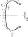
- FIG. 1 is a cross-sectional view in a tire meridian direction illustrating a pneumatic tire 1A (1B) according to an embodiment of the present invention.
- This drawing illustrates a radial tire for use on a passenger car as an example of the pneumatic tire 1A.
- CL refers to a tire equator plane.
- the pneumatic tire 1A includes a pair of bead cores 11, 11, a pair of bead fillers 12, 12, a carcass layer 13, a belt layer 14, tread rubber 15, a pair of side wall rubbers 16,16, and a pair of rim cushion rubbers 17,17 (see FIG. 1 ).
- the pair of bead cores 11, 11 have annular structures and constitute cores of left and right bead portions.
- the pair of bead fillers 12, 12 is disposed on a periphery of each of the pair of bead cores 11, 11 in the tire radial direction so as to reinforce the bead portions.
- the carcass layer 13 has a single-layer structure, and stretches between the left and right bead cores 11, 11 in toroidal form, forming a framework for the tire. Additionally, both ends of the carcass layer 13 are folded toward an outer side in the tire width direction so as to envelop the bead cores 11 and the bead fillers 12, and fixed. Also, the carcass layer 13 is constituted by a plurality of carcass cords formed from steel or organic fibers (e.g.
- aramid, nylon, polyester, rayon, or the like covered by a coating rubber and subjected to a rolling process, and has a carcass angle (inclination angle of the carcass cord in the fiber direction with respect to the tire circumferential direction), as an absolute value, of not less than 85 degrees and not more than 95 degrees.
- the belt layer 14 is formed by laminating a pair of cross belts 141, 142, and a belt cover 143, disposed on the periphery of the carcass layer 13.
- the pair of cross belts 141, 142 are constituted by a plurality of belt cords formed from steel or organic fibers, covered by coating rubber, and subjected to a rolling process, having a belt angle, as an absolute value, of not less than 10 degrees and not more than 30 degrees.
- each of the belts of the pair of cross belts 141, 142 has a belt angle (inclination angle in the fiber direction of the belt cord with respect to the tire circumferential direction) denoted with a mutually different symbol, and the belts are stacked so as to intersect each other in the belt cord fiber directions (crossply configuration).
- the belt cover 143 is configured by a plurality of belt cords formed from steel or organic fibers, covered by coating rubber, and subjected to a rolling process, having a belt angle, as an absolute value, of not less than 10 degrees and not more than 45 degrees. Also, the belt cover 143 is disposed so as to be laminated on the outer side in the tire radial direction of the cross belts 141, 142.
- the tread rubber 15 is disposed on an outer circumference in the tire radial direction of the carcass layer 13 and the belt layer 14, and forms a tread portion of the tire.
- the pair of side wall rubbers 16, 16 is disposed on each outer side of the carcass layer 13 in the tire width direction, so as to form left and right sidewall portions of the tire.
- the pair rim cushion rubbers 17 and 17 is disposed on each outer side of the left and right bead cores 11, 11 and the bead fillers 12, 12 in the tire width direction so as to form left and right bead portions of the tire.
- FIG. 2 is a plan view illustrating a tread surface of the pneumatic tire 1A depicted in FIG. 1 .
- This drawing illustrates a typical block pattern.
- the symbol T is the tire ground contact edge.
- the pneumatic tire 1A includes a plurality of circumferential main grooves 21, 22 extending in the tire circumferential direction, a plurality of land portions 31, 32 partitioned by the circumferential main grooves 21, 22, and a plurality of lug grooves 41, 42 extending in the tire width direction.
- the pneumatic tire 1A includes a plurality of blocks 311, 321 partitioned by the circumferential main grooves 21, 22 and the lug grooves 41, 42.
- Circumferential main groove refers to a circumferential groove having a groove width W1 of not less than 3.0 mm.
- lug groove refers to a lateral groove having a groove width of not less than 2.0 mm.
- the three circumferential main grooves 21, 22 have a straight shape, disposed with left-right symmetry about the tire equatorial plane CL as center.
- two rows of center land portions 31, 31 and a pair of left and right shoulder land portions 32, 32 are partitioned by these circumferential main grooves 21, 22.
- each of the land portions 31, 32 has a plurality of lug grooves 41, 42, respectively.
- each of the lug grooves 41, 42 has an open structure that crosses the land portions 31, 32, and is disposed at predetermined intervals in the tire circumferential direction. In this way, each of the land portions 31, 32 is partitioned into the plurality of blocks 311, 321 having a rectangular shape.
- each of the land portions 31, 32 is a row of blocks formed from the plurality of blocks 311, 321.
- at least one land portion may be a row of blocks.
- the center land portions 31, 31 are rows of blocks, and the left and right shoulder land portions 32, 32 may be ribs (not illustrated on the drawings).
- the lug groove 42 of the shoulder land portion 32 can be envisaged to be configured with a semi-closed structure that terminates within the shoulder land portion 32.
- the developed tread width TDW and the distance Wce between the left and right outermost circumferential main grooves 22, 22 are within the range 0.3 ⁇ Wcs/TDW ⁇ 0.7.
- the left and right outermost circumferential main grooves 22, 22 are disposed with left-right symmetry about the tire equatorial plane CL as center, so the distances Wsh, Wsh on the left and right from the outermost circumferential main grooves 22, 22 to the end of the tread are equal.
- the developed tread width TDW refers to the straight line distance between the two ends of the tread pattern portion of the tire on a developed view when the tire is assembled on a regular rim and the regular inner pressure is applied under no load conditions.
- standard rim refers to an "applicable rim” defined by the Japan Automobile Tyre Manufacturers Association (JATMA), a “design rim” defined by the Tire and Rim Association (TRA), or a “measuring rim” defined by the European Tyre and Rim Technical Organisation (ETRTO).
- JATMA Japan Automobile Tyre Manufacturers Association
- TRA Tire and Rim Association
- ETRTO European Tyre and Rim Technical Organisation
- Regular inner pressure refers to "maximum air pressure” stipulated by JATMA, a maximum value in “tire load limits at various cold inflation pressures” defined by TRA, and “inflation pressures” stipulated by ETRTO.
- regular load refers to "maximum load capacity” stipulated by JATMA, a maximum value in “tire load limits at various cold inflation pressures” defined by TRA, and “load capacity” stipulated by ETRTO.
- JATMA in the case of passenger car tires, the regular internal pressure is an air pressure of 180 kPa, and the regular load is 88% of the maximum load capacity.
- FIG. 3 is an enlarged view illustrating the main portion of the pneumatic tire 1A depicted in FIG. 2 . This drawing illustrates a row of blocks of the center land portion 31.
- the blocks 311 of the center land portion 31 have bent grooves 5a, 5b (see FIG. 2 and FIG. 3 ).
- the bent grooves 5a, 5b have a bent shape that is convex in one direction in the tire width direction, and extend in the tire circumferential direction dividing the block 311 into two in the tire width direction. Also, blocks 311 that are adjacent to each other in the tire circumferential direction are disposed such that the bend directions of the bent grooves 5a, 5b are alternately reversed.
- Bent grooves 5a, 5b refers to grooves having a refracted shape or a curved shape, and includes, for example, grooves with a V-shape, a U-shape, an arc-shape, or the like.
- each block 311 of the left and right center land portion 31, 31 has the bent groove 5a, or 5b.
- one of the bent grooves 5a, 5b is disposed in one block 311.
- the bent grooves 5a, 5b have a V-shape that is convex in only one direction in the tire width direction, and both edges are open in the edge portions of the block 311 in the tire circumferential direction.
- the blocks 311 are divided into left and right small block portions by the bent grooves 5a, 5b.
- the blocks 311 are provided with the bent grooves 5a, 5b that are convex in the tire width direction, so the edge component of the blocks 311 is increased, and the snow performance of the tire is improved. Also, the groove area of the land portions 31 is increased by the bent grooves 5a, 5b, and, the drainage properties of the land portions 31 are improved by extending the bent grooves 5a, 5b in the tire circumferential direction, so the tire wet performance is improved.
- the blocks 311, 311 that are adjacent to each other in the tire circumferential direction are disposed such that the bend directions of the bent grooves 5a, 5b are alternately reversed, so collapse of the blocks 311 in the tire width direction is suppressed, and the steering stability performance of the tire is ensured.
- the left and right center land portions 31 only have the bent grooves 5a, 5b.
- the left and right shoulder land portions 32, 32 may also have the bent grooves 5a, 5b (not illustrated on the drawings).
- at least one row of center land portions may have the bent grooves 5a, 5b.
- the groove width W1 of the circumferential main groove 22 and the groove width W3 of the bent grooves 5a, 5b have the relationship 0.2 ⁇ W3/W1 ⁇ 0.8, and more preferably have the relationship 0.3 ⁇ W3/W1 ⁇ 0.6 (see FIG. 3 ).
- the groove width W1 of the circumferential main groove 22 is measured as the groove width of the circumferential main groove 22 that partitions the edge portion on the outer side in the tire width direction of the blocks 311 having the bent grooves 5a, 5b (in FIG. 2 , the outermost circumferential main groove 22).
- the groove width W3 of the bent grooves 5a, 5b are measured as the groove width of the linear section, as illustrated in FIG. 3 .
- the groove depth H1 of the circumferential main grooves 22 (not illustrated on the drawings) and the groove depth H3 of the bent grooves 5a, 5b (not illustrated on the drawings) have the relationship 0.3 ⁇ H3/H1 ⁇ 0.8, and more preferably have the relationship 0.4 ⁇ H3/H1 ⁇ 0.6.
- the groove depth H1 of the circumferential main groove 22 is measured as the groove depth of the circumferential main groove 22 that partitions the edge portion on the outer side in the tire width direction of the blocks 311 having the bent grooves 5a, 5b.
- the groove depth H1 of the circumferential main grooves 22 and the groove depth H3 of the bent grooves 5a, 5b are measured as the maximum groove depth, excluding raised bottom portions of the groove bottoms, and the like.
- the bend angles ⁇ a, ⁇ b of the bent grooves 5a, 5b are within the range 90 degrees ⁇ ⁇ a ⁇ 150 degrees, and 90 degrees ⁇ ⁇ b ⁇ 150 degrees, and more preferably within the range 100 degrees ⁇ ⁇ a ⁇ 130 degrees, and 100 degrees ⁇ ⁇ b ⁇ 130 degrees (see FIG. 3 ). Also, preferably the bend angles ⁇ a, ⁇ b of the bent grooves 5a, 5b of blocks 311, 311 that are adjacent to each other in the tire circumferential direction have the relationship 10 degrees ⁇
- the angle formed between the lines joining the center point of the curved portion and the two openings of the bent grooves 5a, 5b constitutes the bend angles ⁇ a, ⁇ b of the bent grooves 5a, 5b.
- the bent portion of the bent grooves 5a, 5b is disposed in the center region when the block 311 is divided into three equal portions in the tire circumferential direction (see FIG. 3 ).
- the bent grooves 5a, 5b have bent portions in the center portion (1/3rd region) in the tire circumferential direction, and linear sections in the two end portions (the other 2/3rd regions).
- the center point of the curved portion constitutes the bent portion of the bent grooves 5a, 5b.
- the openings of the bent groove 5a (5b) are disposed offset with respect to the openings of the bent grooves 5a, 5b of at least one of the blocks 311 that are adjacent in the tire circumferential direction (see FIG. 2 ). Therefore, in adjacent blocks 311 in the tire circumferential direction, the bent grooves 5a, 5b of each of the blocks 311 are disposed mutually separated (are not continuous in the tire circumferential direction) at at least one opening.
- one of the openings of one of the bent grooves 5a (5b) is disposed opposite the opening of the bent groove 5b (5a) of one of the adjacent blocks 311 in the tire circumferential direction, and, the other opening is disposed offset with respect to the opening of the bent groove 5b (5a) of the other adjacent block 311 in the tire circumferential direction. Therefore, a pair of bent grooves 5a, 5b that are adjacent to each other in the tire circumferential direction is disposed continuous by having the openings opposite each other. Also, if one set is a pair of such bent grooves 5a, 5b, a plurality of sets of bent grooves 5a, 5b is disposed discontinuously by offsetting the openings from each other.
- one block 311 has a single bent groove 5a (5b).
- a single block 311 may have a plurality of bent grooves 5a, 5b (not illustrated on the drawings).
- the blocks 311 with the bent grooves 5a, 5b are provided with notch grooves 6a, 6b (see FIG. 2 and FIG. 3 ).
- the notch grooves 6a, 6b open into the edge portion of the block 311 in the tire width direction at a first end portion thereof, and a second end portion thereof terminate within the block 311 without intersecting the bent grooves 5a, 5b.
- the blocks 311 in the center land portion 31 each have one bent groove 5a (5b) and one notch groove 6a (6b).
- the notch grooves 6a, 6b have a linear form, extending from the edge portion on the outer side of the block 311 in the tire width direction toward the tire equatorial plane CL, and terminating before the bent grooves 5a, 5b.
- the blocks 321 on the shoulder land portions 32 also have notch grooves 7 in the edge portions on the inner side in the tire width direction.
- the edge component of the blocks 311 is increased, and the snow performance of the tire is improved. Also, because the notch grooves 6a, 6b and the bent grooves 5a, 5b do not intersect, the stiffness of the blocks 311 is properly ensured, and the tire steering stability performance is ensured.
- the notch grooves 6a, 6b are disposed in the edge portions on the outer side in the tire width direction of the blocks 311.
- the notch grooves 6a, 6b may be disposed in the edge portions on the inner side in the tire width direction of the blocks 311 (not illustrated on the drawings), and they may be disposed in the edge portions both on the outer side in the tire width direction and the inner side in the tire width direction of the blocks 311 (not illustrated on the drawings).
- the groove length Lb of the notch groove 6b on the bend side of the bent groove 5b and the groove length La of the notch groove 6a on the opposite side to the bend side of the bent groove 5a have the relationship La > Lb. Therefore, the groove lengths La, Lb of the notch grooves 6a, 6b are adjusted in accordance with their positional relationship to the bent grooves 5a, 5b.
- the groove length of the notch grooves refers to the groove length from the openings of the notch grooves 6a, 6b in the edge portions of the blocks 311 to the terminating portion of the notch grooves 6a, 6b within the blocks 311.
- the notch grooves 6a, 6b are disposed in the edge portions on the outer side in the tire width direction of the blocks 311.
- the notch groove 6b having a short groove length Lb is disposed with the bent groove 5b that is convex to the outer side in the tire width direction
- the notch groove 6a having a long groove length La is disposed with the bent groove 5a that is convex to the inner side in the tire width direction.
- the groove width W1 of the circumferential main groove 22 and the groove width W4 of the notch grooves 6a, 6b have the relationship 0.2 ⁇ W4/W1 ⁇ 0.8, and more preferably have the relationship 0.3 ⁇ W4/W1 ⁇ 0.6 (see FIG. 3 ).
- the stiffness as a block pattern is properly ensured.
- the groove depth H1 of the circumferential main grooves 22 and the groove depth H4 of the notch grooves 6a, 6b (not illustrated on the drawings) have the relationship 0.1 ⁇ H4/H1 ⁇ 0.6, and more preferably have the relationship 0.2 ⁇ H4/H1 ⁇ 0.4.
- the groove depth H4 of the notch grooves 6a, 6b is measured as the maximum groove depth, excluding raised bottom portions of the groove bottoms, and the like.
- the notch grooves 6a, 6b are disposed in the center region when the block 311 is divided into three equal portions in the tire circumferential direction (see FIG. 3 ).
- both the bent portion of the bent groove 5a (5b) and the notch groove 6a (6b) are disposed in the center portion in the tire circumferential direction of the block 311.
- the point of intersection of the imaginary line extending from the notch groove 6a having the groove length La and the bent groove 5a is obtained.
- the distance Lc between this intersection point and the opening in the edge portion of the block 311 of the notch groove 6a is within the range 0.2 ⁇ La/Lc ⁇ 0.6.
- the point of intersection of the imaginary line extending from the notch groove 6b having the groove length Lb and the bent groove 5b is obtained.
- the distance Ld between this intersection point and the opening in the edge portion of the block 311 of the notch groove 6b is within the range 0.2 ⁇ Lb/Ld ⁇ 0.6.
- the ratio La/Lc and the ratio Lb/Ld have the relationship 0.90 ⁇ (La/Lc)/(Lb/Ld) ⁇ 1.10.
- the inclination angles ⁇ a, ⁇ b with respect to the tire circumferential direction of the notch grooves 6a, 6b in a pair of blocks 311, 311 that are adjacent to each other in the tire circumferential direction are within the range
- each of the notch grooves 6a, 6b are disposed substantially parallel.
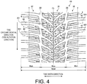
- FIG. 4 is an explanatory view of a modified example of the pneumatic tire 1A depicted in FIG. 1 .
- This drawing illustrates a winter tire for use on passenger cars that has a directional tread pattern.
- FIG. 5 is an enlarged view illustrating the main portion of a pneumatic tire 1B depicted in FIG. 4 .
- This drawing illustrates a row of blocks on one side of the center land portion 31.
- constituent elements that are the same as those described for the tread pattern of the pneumatic tire 1A depicted in FIG. 1 (see FIG. 2 ) are assigned the same reference numerals and descriptions thereof are omitted.
- the pneumatic tire 1B includes two circumferential main grooves 22, 22 having a zigzag shape, one row of the center land portion 31 partitioned by the circumferential main grooves 22, 22 and a pair of left and right shoulder land portions 32, 32. Therefore, compared with the configuration in FIG. 2 , a single wide center land portion 31 is partitioned.
- lug groove 41, 42 is provided in the center land portion 31 and the left and right shoulder land portions 32, 32, respectively of the pneumatic tire 1B.
- the lug groove 41 is an inclined lug groove that extends at an inclination at a predetermined angle of inclination ⁇ with respect to the tire circumferential direction, a first end portion thereof opens into the circumferential main groove 22, and a second end portion thereof extends beyond the tire equatorial plane CL and terminates within the center land portion 31.
- the lug grooves 41 that open into one of the circumferential main grooves 22 and the lug grooves 41 that open into the other of the circumferential main grooves 22 are disposed at predetermined intervals in the tire circumferential direction and alternately left and right. Also, two lug grooves 41, 41 that extend from one of the circumferential main grooves 22 toward the tire equatorial plane CL, and one lug groove 41 that extends from the other of the circumferential main grooves 22 toward the tire equatorial plane CL intersect within the center land portion 31.
- the center land portion 31 is divided by the lug grooves 41 into a mesh-like form, and a row of blocks is partitioned that includes a plurality of the blocks 311 arranged in a staggered manner in the tire circumferential direction.
- the lug grooves 41, 41 of the center land portion 31 extend at an inclination at the predetermined angle of inclination ⁇ from the left and right circumferential main grooves 22, 22 beyond the tire equatorial plane CL and intersect.
- the drainage properties of the center land portion 31 are improved, and the tire wet performance is improved.
- the edge component of the center land portion 31 is increased, so the snow performance of the tire is improved.
- one block 311 is partitioned.
- one block 311 may be partitioned by intersecting one lug groove 41 that extends from one of the circumferential main grooves 22 and one lug groove 41 that extends from the other of the circumferential main grooves 22 (not illustrated on the drawings).
- the center land portion 31 is divided in the tire circumferential direction by the lug grooves 41, so a row of blocks formed from the plurality of blocks 311 is partitioned.
- the groove width W2 of the lug groove 41 increases from the tire equatorial plane CL toward the outer side in the tire width direction.
- the angle of inclination ⁇ of the lug groove 41 increases from the tire equatorial plane CL toward the outer side in the tire width direction.
- the angle of inclination ⁇ of the lug groove 41 is within the range 20 degrees ⁇ ⁇ ⁇ 80 degrees. As a result, the drainage properties of the lug groove 41 are improved.
- each of the blocks 311, 321 of the center land portion 31 and the shoulder land portions 32 has a plurality of sipes 8.
- the edge component of the blocks 311, 321 is increased, so the tire snow performance is increased.
- Sipe refers to a cut formed in a land portion, typically with a sipe width of less than 1.5 mm (not illustrated on the drawings).
- the blocks 311 in the center land portion 31 each have the bent grooves 5a, 5b. Also, each of the blocks 311 having the bent grooves 5a, 5b has the notch grooves 6a, 6b.
- the amplitude D1 of the zigzag shape of the circumferential main groove 22 and the amplitude D2 in the tire width direction of the bent grooves 5a, 5b have the relationship D1 ⁇ D2.
- These amplitudes D1, D2 are measured using the maximum width positions of the range of extension of the groove in the tire width direction as standard.
- the notch grooves 6a, 6b are inclined with respect to the tire circumferential direction following the inclination of the lug grooves 41.
- the inclination angles ⁇ a, ⁇ b with respect to the tire circumferential direction of the notch grooves 6a, 6b are within the range 60 degrees ⁇ ⁇ a ⁇ 120 degrees and 60 degrees ⁇ ⁇ b ⁇ 120 degrees.
- the developed tread width TDW and the distance Wce between the left and right outermost circumferential main grooves 22, 22 are within the range 0.4 ⁇ Wce/TDW ⁇ 0.8.
- the left and right outermost circumferential main grooves 22, 22 are disposed with left-right symmetry about the tire equatorial plane CL as center, so the distances Wsh, Wsh on the left and right from the outermost circumferential main grooves 22, 22 to the end of the tread are equal.
- the bent portions of the bent grooves 5a, 5b of the blocks 311, 311 that are adjacent in the tire width direction are disposed at the same position relative to each other with respect to the tire circumferential direction.
- the bent shape of the bent grooves 5a, 5b of the blocks 311, 311 that are adjacent in the tire width direction are disposed such that the bend directions with respect to the tire width direction are reversed with respect to each other.
- the plurality of blocks 311 is disposed in a staggered manner in the tire circumferential direction, so the bent portions of the bent grooves 5a, 5b of the blocks 311, 311 that are adjacent in the tire width direction are disposed in positions offset from each other in the tire circumferential direction. Also, the bent shapes of the bent grooves 5a, 5b of the blocks 311, 311 that are adjacent to each other in the tire width direction are disposed with their phases offset with respect to each other.
- the pneumatic tire 1A includes the plurality of circumferential main grooves 21, 22 extending in the tire circumferential direction, the plurality of lug grooves 41 extending in the tire width direction, and the plurality of blocks 311 partitioned by the circumferential main grooves 21, 22 and the lug grooves 41 (see FIGS. 2 and 3 ).
- the block 311 has a bent groove 5a (5b) having a bent shape that is convex in one direction that extends in the tire circumferential direction dividing the block 311 into two in the tire width direction.
- the blocks 311, 311 that are adjacent to each other in the tire circumferential direction are disposed such that the bend directions of the bent grooves 5a, 5b are alternately reversed.
- the blocks 311 are provided with the bent grooves 5a, 5b that are convex in the tire width direction, so the edge component of the blocks 311 is increased, and this has the advantage that the snow performance of the tire is improved.
- the groove area of the land portions 31 is increased by the bent grooves 5a, 5b, and, the drainage properties of the land portions 31 are improved by extending the bent grooves 5a, 5b in the tire circumferential direction, and this has the advantage that the tire wet performance is improved.
- the blocks 311, 311 that are adjacent to each other in the tire circumferential direction are disposed such that the bend directions of the bent grooves 5a, 5b are alternately reversed, so collapse of the blocks 311 in the tire width direction is suppressed, and this has the advantage that the steering stability performance of the tire is ensured.
- the blocks 311 having the bent groove 5a (5b) have the notch grooves 6a (6b) that at a first end portion thereof open into the edge portion in the tire width direction of the blocks 311 and at a second end portion thereof terminate within the blocks 311 without intersecting the bent groove 5a (5b) (see FIGS. 2 to 5 ).
- the edge component of the blocks 311 is increased, which has the advantage that the tire snow performance is improved.
- the notch grooves 6a, 6b and the bent grooves 5a, 5b do not intersect, the stiffness of the blocks 311 is properly ensured, which has the advantage that the tire steering stability performance is ensured.
- the plurality of bent grooves 5a, 5b are provided in the blocks 311 that are adjacent in the tire width direction (see FIG. 4 ). Thereby, the edge component of the center land portion 31 is increased, which has the advantage that the snow performance of the tire is improved.
- the bent shapes of the bent grooves 5a, 5b of the blocks 311, 311 that are adjacent to each other in the tire width direction are disposed with their phases offset with respect to each other (see FIG. 4 ).
- the stiffness of the land portions 31 in the entire periphery of the tire is made uniform, which has the advantage that the tire wet performance is improved.
- the groove length Lb of the notch groove 6b on the bend side of the bent groove 5b, and the groove length La of the notch groove 6a on the opposite side to the bend side of the bent groove 5a have the relationship La>Lb (see FIG. 3 and FIG. 5 ).
- the groove lengths La, Lb of the notch grooves 6a, 6b are adjusted in accordance with the positional relationship with the bent grooves 5a, 5b, so the stiffness of the blocks 311 is properly ensured, which has the advantage that the steering stability performance of the tire is ensured.
- the notch groove 6a (6b) is disposed on the edge portion on the outer side in the tire width direction of the blocks 311 having the bent groove 5a (5b) (see FIGS. 2 to 5 ).
- the notch grooves 6a, 6b are opened into the edge portions on the outer side in the tire width direction of the blocks 311, the drainage properties of the land portions 31 are improved, which has the advantage that the tire wet performance is improved.
- the groove width W1 of the circumferential main groove 22 and the groove width W3 of the bent grooves 5a, 5b have the relationship 0.2 ⁇ W3/W1 ⁇ 0.8 (see FIG. 3 and FIG. 5 ).
- the groove width W3 of the bent grooves 5a, 5b is made appropriate, which has the advantage that the tire wet performance is improved.
- the drainage properties of the bent grooves 5a, 5b are properly ensured.
- W3/W1 ⁇ 0.8 the stiffness of the land portion 31 is properly ensured.
- the groove depth H1 of the circumferential main groove 22 and the groove depth H3 of the bent grooves 5a, 5b have the relationship 0.3 ⁇ H3/H1 ⁇ 0.8.
- the groove depth H3 of the bent grooves 5a, 5b is made appropriate, which has the advantage that the tire wet performance is improved.
- the drainage properties of the bent grooves 5a, 5b are properly ensured.
- H3/H1 ⁇ 0.8 the stiffness of the land portion 31 is properly ensured.
- the bend angle ⁇ ( ⁇ a, ⁇ b) of the bent grooves 5a, 5b is within the range 90 degrees ⁇ 150 degrees (see FIG. 3 and FIG. 5 ).
- the bend angles ⁇ of the bent grooves 5a, 5b are made appropriate, which has the advantage that the snow performance of the tire is improved.
- the stiffness of the land portion 31 is properly ensured.
- ⁇ 150 degrees the edge component of the bent grooves 5a, 5b is increased, so the snow performance is increased.
- the groove width W1 of the circumferential main groove 22 and the groove width W4 of the notch grooves 6a, 6b have the relationship 0.2 ⁇ W4/W1 ⁇ 0.8 (see FIG. 3 and FIG. 5 ).
- the groove width W4 of the notch grooves 6a, 6b is made appropriate, which has the advantage that the tire wet performance is improved.
- the drainage properties of the notch grooves 6a, 6b are properly ensured.
- W4/W1 ⁇ 0.8 the stiffness of the land portion 31 is properly ensured.
- the groove depth H1 of the circumferential main groove 22 and the groove depth H4 of the notch grooves 6a, 6b have the relationship 0.1 ⁇ H4/H1 ⁇ 0.6.
- the groove depth H4 of the notch grooves 6a, 6b is made appropriate, which has the advantage that the tire wet performance is improved.
- the drainage properties of the notch grooves 6a, 6b are properly ensured.
- H4/H1 ⁇ 0.6 the stiffness of the land portion 31 is properly ensured.
- the bent portion of the bent grooves 5a, 5b are disposed in the center region when the block 311 is divided into three equal portions in the tire circumferential direction (see FIG. 3 and FIG. 5 ).
- the bent portion of the bent grooves 5a, 5b is disposed in the center portion of the blocks 311, which has the advantage that the uneven wear resistance of the blocks 311 is properly ensured.
- the notch grooves 6a, 6b are disposed in the center region when the block 311 is divided into three equal portions in the tire circumferential direction (see FIG. 3 and FIG. 5 ).
- the notch grooves 6a, 6b are disposed in the center portion of the blocks 311, which has the advantage that the uneven wear resistance of the blocks 311 is properly ensured.
- the distance Lc between the point of intersection of the bent groove 5a and an imaginary line extended from the notch groove 6a having the groove length La in one of the blocks 311 and the opening of the notch groove 6a in the edge portion of the block 311 is within the range 0.2 ⁇ La/Lc ⁇ 0.6 (see FIG. 3 and FIG. 5 ).
- the distance Ld between the point of intersection of the bent groove 5b and an imaginary line extended from the notch groove 6b having the groove length Lb in the other of the blocks 311 and the opening of the notch groove 6b in the edge portion of the block 311 is within the range 0.2 ⁇ Lb/Ld ⁇ 0.6.
- the ratio La/Lc and the ratio Lb/Ld have the relationship 0.90 ⁇ (La/Lc)/(Lb/Ld) ⁇ 1.10.
- the bend angles ⁇ a, ⁇ b of the bent grooves 5a, 5b are within the range 10 degrees ⁇
- the bend angles ⁇ a, ⁇ b of the bent grooves 5a, 5b of adjacent blocks 311, 311 are made appropriate, which has the advantage that the steering stability performance of the tire is improved.
- the bend angles ⁇ a, ⁇ b of the bent grooves 5a, 5b of adjacent blocks 311, 311 are made appropriate, which has the advantage that the steering stability performance of the tire is improved.
- the mutual support action of the portions of the blocks 311, 311 divided by the bent grooves 5a, 5b is ensured.
- the inclination angles ⁇ a, ⁇ b with respect to the tire circumferential direction of the notch grooves 6a, 6b in a pair of blocks 311, 311 that are adjacent to each other in the tire circumferential direction are within the range
- the notch grooves 6a, 6b of adjacent blocks 311, 311 are disposed substantially parallel. This has the advantage that the uneven wear resistance performance of the tire is improved.
- the opening of the bent groove 5a (5b) is disposed offset with respect to the opening of the bent groove 5b (5a) of at least one of the blocks 311 that are adjacent in the tire circumferential direction (see FIG. 3 and FIG. 5 ).
- the edge effect of the land portion 31 is increased, which has the advantage that the snow performance of the tire is improved.
- the pneumatic tire 1B includes two circumferential main grooves 22, 22 extending in the tire circumferential direction, and one row of the center land portion 31 and the pair of left and right shoulder land portions 32, 32 partitioned by the circumferential main grooves 22, 22, and the plurality of lug grooves 41 disposed in the center land portion 31 (see FIG. 4 ).
- the lug groove 41 of the center land portion 31 is an inclined lug groove that extends at an inclination at a predetermined angle of inclination ⁇ with respect to the tire circumferential direction, a first end portion thereof opens into the circumferential main groove 22, and a second end portion thereof terminates within the center land portion 31.
- the center land portion 31 is divided into a plurality of blocks 311 by intersecting within the center land portion 31 a lug groove 41 that extends from one of the circumferential main grooves 22 and a lug groove 41 that extends from the other of the circumferential main grooves 22.
- the block 311 has a bent groove 5a (5b) having a bent shape that is convex in one direction that extends in the tire circumferential direction dividing the block 311 into two in the tire width direction.
- the blocks 311, 311 that are adjacent to each other in the tire circumferential direction are disposed such that the bend directions of the bent grooves 5a, 5b are alternately reversed.
- the lug grooves 41, 41 of the center land portions 31 extend at an inclination at the predetermined angle of inclination ⁇ from the left and right circumferential main grooves 22, 22 beyond the tire equatorial plane CL, and intersect.
- the drainage properties of the center land portion 31 are improved, and this has the advantage that the tire wet performance is improved.
- the edge component of the center land portion 31 is increased, which has the advantage that the snow performance of the tire is improved.
- the blocks 311 are provided with the bent grooves 5a, 5b that are convex in the tire width direction, so the edge component of the blocks 311 is increased, and this has the advantage that the snow performance of the tire is improved.
- the groove area of the land portions 31 is increased by the bent grooves 5a, 5b, and, the drainage properties of the land portions 31 are improved by extending the bent grooves 5a, 5b in the tire circumferential direction, and this has the advantage that the tire wet performance is further improved.
- the blocks 311, 311 that are adjacent to each other in the tire circumferential direction are disposed such that the bend directions of the bent grooves 5a, 5b are alternately reversed, so collapse of the blocks 311 in the tire width direction is suppressed, and this has the advantage that the steering stability performance of the tire is ensured.
- the circumferential main grooves 22 have a zigzag shape (see FIG. 4 ). Thereby, the edge component of the land portions 31, 32 is increased, which has the advantage that the snow performance of the tire is improved.
- the amplitude D1 of the zigzag shape of the circumferential main groove 22 and the amplitude D2 in the tire width direction of the bent grooves 5a, 5b have the relationship D1 ⁇ D2 (see FIG. 5 ). This has the advantage that both the water drainage properties of the tire and the edge effect due to the circumferential main grooves 22 and the bent grooves 5a, 5b are achieved.
- the groove width W2 of the lug grooves 41 increases from the tire equatorial plane CL toward the outer side in the tire width direction (see FIG. 5 ). Thereby, the water drainage performance of the lug grooves 41 is improved, which has the advantage that the tire wet performance is improved.
- the angle of inclination ⁇ of the lug grooves 41 increases from the tire equatorial plane CL toward the outer side in the tire width direction (see FIG. 5 ).
- the water drainage performance of the lug grooves 41 in the region close to the tire equatorial plane CL is improved, which has the advantage that the wet performance of the tire is improved.
- the edge component of the lug grooves 41 in the region on the outer side in the tire width direction is increased, which has the advantage that the tire snow performance is improved.
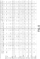
- FIG. 6 is a table showing results of performance testing of pneumatic tires according to embodiments of the present invention.
- a plurality of mutually differing pneumatic tires was evaluated for (1) snow performance, (2) wet performance, and (3) steering stability performance (see FIG. 6 ).
- pneumatic tires with a tire size of 205/55R16 91H were assembled on a rim having a rim size of 16x6.5JJ, and an air pressure of 230 kPa and the maximum load defined by JATMA were applied to these pneumatic tires.
- the pneumatic tires were fitted to a 1600 cc displacement front-engine front-drive (FF) test vehicle.
- Working Examples 1 to 16 were pneumatic tires having tread patterns as depicted in FIGS. 4 and 5 .
- the pneumatic tire of Comparative Example did not have the bent grooves 5a, 5b and the notch grooves 6a, 6b in the tread patterns depicted in FIGS. 4 and 5 .
Landscapes
- Engineering & Computer Science (AREA)
- Mechanical Engineering (AREA)
- Tires In General (AREA)
Claims (22)
- Luftreifen (1A, 1B), umfassend:eine Mehrzahl von Hauptumfangsrillen (21, 22), die in Reifenumfangsrichtung verlaufen;eine Mehrzahl von Stollenrillen (41, 42), die in Reifenbreitenrichtung verlaufen;undeine Mehrzahl von Blöcken (311, 321), die von den Hauptumfangsrillen (21, 22) und den Stollenrillen (41, 42) unterteilt werden, dadurch gekennzeichnet, dass die Blöcke (311), die eine gebogene Rille (5, 5a, 5b) einschließen, eine gebogene Form aufweisen, die in einer Richtung konvex ist und die in Reifenumfangsrichtung verläuft, wodurch der Block (311) in Reifenbreitenrichtung zweigeteilt wird, und wobei die Blöcke (311), die in Reifenumfangsrichtung aneinander angrenzend sind, so angeordnet sind, dass die Biegerichtung der gebogenen Rillen (5, 5a, 5b) alternierend umgekehrt wird.
- Luftreifen (1A, 1B) gemäß Anspruch 1, wobei die Blöcke (311), die die gebogenen Rillen (5, 5a, 5b) aufweisen, eine Kerbrille (6a, 6b) aufweisen, bei der ein erster Endabschnitt davon sich in einen Randabschnitt in Reifenbreitenrichtung des Blocks (311) öffnet und ein zweiter Endabschnitt davon innerhalb des Blocks (311) endet, ohne die gebogene Rille (5a, 5b) zu überschneiden.
- Luftreifen (1A, 1B) gemäß Anspruch 1 oder 2, wobei Blöcke (311), die in Reifenbreitenrichtung aneinander angrenzend sind, eine Mehrzahl von gebogenen Rillen (5a, 5b) aufweisen.
- Luftreifen (1A, 1B) gemäß einem der Ansprüche 1 bis 3, wobei die gebogenen Formen der gebogenen Rillen (5a, 5b) der Blöcke (311), die in Reifenbreitenrichtung aneinander angrenzend sind, so angeordnet sind, dass ihre Phasen in Bezug zueinander versetzt sind.
- Luftreifen (1A, 1B) gemäß einem der Ansprüche 2 bis 4, wobei die Rillenlänge Lb der Kerbrille (6b) auf der Biegungsseite der gebogenen Rille (5b) und die Rillenlänge La der Kerbrille (6a) auf der gegenüberliegenden Seite der Biegungsseite der gebogenen Rille (5a) die Beziehung La>Lb aufweisen.
- Luftreifen (1A, 1B) gemäß einem der Ansprüche 2 bis 5; wobei die Kerbrillen (6a, 6b) am Randabschnitt auf der Außenseite in Reifenbreitenrichtung der Blöcke (311), die die gebogenen Rillen (5a, 5b) aufweisen, angeordnet sind.
- Luftreifen (1A, 1B) gemäß einem der Ansprüche 1 bis 6, wobei die Rillenbreite W1 der Hauptumfangsrillen (21, 22) und die Rillenbreite W3 der gebogenen Rillen (5a, 5b) die Beziehung 0,2≤W3/W1≤0,8 aufweisen.
- Luftreifen (1A, 1B) gemäß einem der Ansprüche 1 bis 7, wobei die Rillentiefe H1 der Hauptumfangsrillen (21, 22) und die Rillentiefe H3 der gebogenen Rillen (5a, 5b) die Beziehung 0,3≤H3/H1≤0,8 aufweisen.
- Luftreifen (1A, 1B) gemäß einem der Ansprüche 1 bis 8, wobei der Biegungswinkel α der gebogenen Rillen (5a, 5b) innerhalb des Bereichs von 90 Grad ≤ α ≤ 150 Grad liegt.
- Luftreifen (1A, 1B) gemäß einem der Ansprüche 2 bis 9, wobei die Rillenbreite W1 der Hauptumfangsrillen (21, 22) und die Rillenbreite W4 der Kerbrillen (6a, 6b) die Beziehung 0,2≤W4/W1≤0,8 aufweisen.
- Luftreifen (1A, 1B) gemäß einem der Ansprüche 2 bis 10, wobei die Rillentiefe H1 der Hauptumfangsrillen (21, 22) und die Rillentiefe H4 der Kerbrillen (6a, 6b) die Beziehung 0,1≤H4/H1≤0,6 aufweisen.
- Luftreifen (1A, 1B) gemäß einem der Ansprüche 1 bis 11, wobei der gebogene Abschnitt der gebogenen Rillen (5a, 5b) im Mittelbereich angeordnet ist, wenn der Block (311) in Reifenumfangsrichtung in drei gleiche Abschnitte unterteilt ist.
- Luftreifen (1A, 1B) gemäß einem der Ansprüche 1 bis 12, wobei die Kerbrille (6a, 6b) im Mittelbereich angeordnet ist, wenn der Block (311) in Reifenumfangsrichtung in drei gleiche Abschnitte unterteilt ist.
- Luftreifen (1A, 1B) gemäß einem der Ansprüche 2 bis 13, wobei bei einem Paar von Blöcken (311), die in Reifenumfangsrichtung aneinander angrenzend sind,
der Abstand Lc zwischen dem Schnittpunkt der gebogenen Rillen (5a) und einer gedachten Linie, die von der Kerbrille (6a) mit der Rillenlänge La in einem der Blöcke (311) und der Öffnung der Kerbrille (6a) im Randabschnitt des Blocks (311) verlängert ist, innerhalb des Bereichs 0,2≤La/Lc≤0,6 liegt,
der Abstand Ld zwischen dem Schnittpunkt der gebogenen Rillen (5b) und einer gedachten Linie, die von der Kerbrille (6b) mit der Rillenlänge Lb in dem anderen der Blöcke (311) und der Öffnung der Kerbrille (6b) im Randabschnitt des Blocks (311) verlängert ist, innerhalb des Bereichs von 0,2≤Lb/Ld≤0,6 liegt, und
das Verhältnis La/Lc und das Verhältnis Lb/Ld die Beziehung 0,9 ≤(La/Lc)/(Lb/Ld)≤ 1,10 aufweisen. - Luftreifen (1A, 1B) gemäß einem der Ansprüche 1 bis 14, wobei bei einem Paar von Blöcken (311), die in Reifenumfangsrichtung aneinander angrenzend sind, die Biegungswinkel αa, αb der gebogenen Rillen (5a, 5b) innerhalb des Bereichs 10 Grad ≤ |αa-αb| ≤ 30 Grad liegen.
- Luftreifen (1A, 1B) gemäß einem der Ansprüche 1 bis 15, wobei bei einem Paar von Blöcken (311), die in Reifenumfangsrichtung aneinander angrenzend sind, die Neigungswinkel βa, βb der Kerbrillen (6a, 6b) in Bezug auf die Reifenumfangsrichtung innerhalb des Bereichs |βa -βb| ≤ 10 Grad liegen.
- Luftreifen (1A, 1B) gemäß einem der Ansprüche 1 bis 16, wobei die Öffnung der gebogenen Rille (5a, 5b) in Bezug auf die Öffnung von mindestens einer der angrenzenden, gebogenen Rillen (5b, 5a) in Reifenumfangsrichtung versetzt angeordnet ist.
- Luftreifen (1B) nach einem der Ansprüche 1 bis 17, ferner umfassend:eine einzelne Reihe eines Mittelstegabschnitts (31) und ein Paar aus linkem und rechtem Schulterstegabschnitt (32), die von den Hauptumfangsrillen (21, 22) unterteilt werden;die Mehrzahl von Stollenrillen (41), die im Mittelstegabschnitt (31) angeordnet sind, wobei die Stollenrillen (41) geneigte Stollenrillen (41) sind, die in einer Neigung mit einem vorgegebenen Neigungswinkel in Bezug auf die Reifenumfangsrichtung verlaufen, wobei ein erster Endabschnitt davon zur Hauptumfangsrille (22) hin geöffnet ist und ein zweiter Endabschnitt davon innerhalb des Mittelstegabschnitts (31) endet,wobei der Mittelstegabschnitt (31) in eine Mehrzahl von Blöcken (311) unterteilt wird, indem er sich mit der Stollenrille (41), die von einer der Hauptumfangsrillen (22) ausgeht, und der Stollenrille (41), die von der anderen der Hauptumfangsrillen (22) ausgeht, innerhalb des Mittelstegabschnitts (31) überschneidet.
- Luftreifen (1B) gemäß einem der Ansprüche 1 bis 18, wobei die Hauptumfangsrillen (22) eine Zickzackform aufweisen.
- Luftreifen (1B) gemäß Anspruch 19, wobei die Amplitude D1 der Zickzackform der Hauptumfangsrillen (22) und die Amplitude D2 in Reifenbreitenrichtung der gebogenen Rillen (5b) die Beziehung D1<D2 aufweisen.
- Luftreifen (1B) gemäß einem der Ansprüche 1 bis 20, wobei die Rillenbreite W2 der Stollenrille (41) von der Reifenäquatorialebene zur Außenseite in Reifenbreitenrichtung zunimmt.
- Luftreifen (1B) gemäß einem der Ansprüche 1 bis 21, wobei der Neigungswinkel der Stollenrillen (41) von der Reifenäquatorialebene zur Außenseite in Reifenbreitenrichtung zunimmt.
Applications Claiming Priority (2)
| Application Number | Priority Date | Filing Date | Title |
|---|---|---|---|
| JP2012053755A JP5617859B2 (ja) | 2012-03-09 | 2012-03-09 | 空気入りタイヤ |
| PCT/JP2013/054588 WO2013133049A1 (ja) | 2012-03-09 | 2013-02-22 | 空気入りタイヤ |
Publications (3)
| Publication Number | Publication Date |
|---|---|
| EP2823973A1 EP2823973A1 (de) | 2015-01-14 |
| EP2823973A4 EP2823973A4 (de) | 2015-10-07 |
| EP2823973B1 true EP2823973B1 (de) | 2017-05-03 |
Family
ID=49116531
Family Applications (1)
| Application Number | Title | Priority Date | Filing Date |
|---|---|---|---|
| EP13757531.2A Not-in-force EP2823973B1 (de) | 2012-03-09 | 2013-02-22 | Luftreifen |
Country Status (7)
| Country | Link |
|---|---|
| US (1) | US10668774B2 (de) |
| EP (1) | EP2823973B1 (de) |
| JP (1) | JP5617859B2 (de) |
| KR (1) | KR101985672B1 (de) |
| CN (1) | CN104159754B (de) |
| RU (1) | RU2564064C1 (de) |
| WO (1) | WO2013133049A1 (de) |
Families Citing this family (23)
| Publication number | Priority date | Publication date | Assignee | Title |
|---|---|---|---|---|
| JP6360459B2 (ja) * | 2015-05-26 | 2018-07-18 | 住友ゴム工業株式会社 | 冬用タイヤ |
| JP2017065605A (ja) * | 2015-10-01 | 2017-04-06 | 住友ゴム工業株式会社 | 自動車用タイヤ |
| EP3176006B1 (de) * | 2015-11-24 | 2018-06-20 | Sumitomo Rubber Industries Limited | Reifen |
| JP6146490B1 (ja) * | 2016-01-19 | 2017-06-14 | 横浜ゴム株式会社 | 空気入りタイヤ |
| JP6724397B2 (ja) * | 2016-02-04 | 2020-07-15 | 住友ゴム工業株式会社 | タイヤ |
| CN108725101B (zh) * | 2017-04-18 | 2021-12-03 | 住友橡胶工业株式会社 | 轮胎 |
| JP6907690B2 (ja) * | 2017-05-16 | 2021-07-21 | 住友ゴム工業株式会社 | タイヤ |
| JP6762267B2 (ja) | 2017-06-07 | 2020-09-30 | 株式会社ブリヂストン | タイヤ |
| US10836215B2 (en) * | 2017-06-27 | 2020-11-17 | Sumitomo Rubber Industries, Ltd. | Tire |
| JP6521115B1 (ja) | 2018-01-30 | 2019-05-29 | 横浜ゴム株式会社 | 空気入りタイヤ |
| JP7091702B2 (ja) * | 2018-02-23 | 2022-06-28 | 住友ゴム工業株式会社 | 冬用タイヤ |
| JP2020006753A (ja) * | 2018-07-04 | 2020-01-16 | 株式会社ブリヂストン | タイヤ |
| JP7302264B2 (ja) * | 2019-04-26 | 2023-07-04 | 横浜ゴム株式会社 | 空気入りタイヤ |
| JP7159968B2 (ja) * | 2019-04-26 | 2022-10-25 | 横浜ゴム株式会社 | 空気入りタイヤ |
| JP7120146B2 (ja) * | 2019-04-26 | 2022-08-17 | 横浜ゴム株式会社 | 空気入りタイヤ |
| JP7388904B2 (ja) * | 2019-12-12 | 2023-11-29 | Toyo Tire株式会社 | 空気入りタイヤ |
| JP7502855B2 (ja) * | 2019-12-13 | 2024-06-19 | Toyo Tire株式会社 | 空気入りタイヤ |
| JP7372550B2 (ja) | 2020-04-14 | 2023-11-01 | 横浜ゴム株式会社 | タイヤ |
| US20230286326A1 (en) * | 2020-07-29 | 2023-09-14 | The Yokohama Rubber Co., Ltd. | Tire |
| JP7808471B2 (ja) * | 2021-12-28 | 2026-01-29 | Toyo Tire株式会社 | 空気入りタイヤ |
| CN114393957A (zh) * | 2022-03-08 | 2022-04-26 | 正新橡胶(中国)有限公司 | 一种轮胎 |
| EP4635755A1 (de) * | 2024-04-18 | 2025-10-22 | Bridgestone Europe NV/SA | Reifen mit verbessertem muster |
| EP4635756A1 (de) * | 2024-04-18 | 2025-10-22 | Bridgestone Europe NV/SA | Reifen mit verbessertem muster |
Family Cites Families (24)
| Publication number | Priority date | Publication date | Assignee | Title |
|---|---|---|---|---|
| US4351381A (en) * | 1978-02-14 | 1982-09-28 | The Goodyear Tire & Rubber Company | Tread for pneumatic tire |
| JPS5853604B2 (ja) * | 1979-12-28 | 1983-11-30 | 株式会社ブリヂストン | ラリ−用タイヤ |
| JPH0390404A (ja) * | 1989-06-08 | 1991-04-16 | Bridgestone Corp | 重荷重用タイヤ |
| JPH03231001A (ja) * | 1990-02-05 | 1991-10-15 | Bridgestone Corp | 重荷重用タイヤ |
| US5238038A (en) * | 1990-09-04 | 1993-08-24 | The Goodyear Tire & Rubber Company | Pneumatic tire |
| US5269357A (en) * | 1991-07-09 | 1993-12-14 | Uniroyal Goodrich Tire Company | Reduced noise generating tread pattern for a tire |
| JPH07108606B2 (ja) * | 1992-10-30 | 1995-11-22 | オーツタイヤ株式会社 | 空気入りタイヤ |
| DE4300695A1 (de) | 1993-01-13 | 1994-07-14 | Sp Reifenwerke Gmbh | Lauffläche für Fahrzeugluftreifen |
| JP3481981B2 (ja) * | 1993-11-22 | 2003-12-22 | 住友ゴム工業株式会社 | 低騒音タイヤ |
| DE69722728T2 (de) * | 1996-08-05 | 2003-12-04 | Sumitomo Rubber Industries Ltd., Kobe | Luftreifen |
| JPH10287110A (ja) * | 1997-04-14 | 1998-10-27 | Bridgestone Corp | 空気入りタイヤ |
| JP2000264018A (ja) | 1999-03-19 | 2000-09-26 | Bridgestone Corp | 空気入りタイヤ |
| JP3913045B2 (ja) * | 2001-11-16 | 2007-05-09 | 横浜ゴム株式会社 | 空気入りタイヤ |
| JP3930391B2 (ja) * | 2002-07-29 | 2007-06-13 | 住友ゴム工業株式会社 | 空気入りタイヤ |
| WO2005005170A1 (ja) * | 2003-07-14 | 2005-01-20 | The Yokohama Rubber Co., Ltd. | 空気入りタイヤ |
| JP4377862B2 (ja) * | 2005-08-04 | 2009-12-02 | 住友ゴム工業株式会社 | 重荷重用空気入りタイヤ |
| JP4928785B2 (ja) * | 2006-01-06 | 2012-05-09 | 株式会社ブリヂストン | 空気入りタイヤ |
| JP5129470B2 (ja) * | 2006-08-24 | 2013-01-30 | 住友ゴム工業株式会社 | 空気入りタイヤ |
| EP2151334B1 (de) * | 2007-05-28 | 2014-09-10 | Bridgestone Corporation | Reifen |
| JP5739869B2 (ja) * | 2010-03-10 | 2015-06-24 | 株式会社ブリヂストン | 空気入りタイヤ |
| JP5018981B2 (ja) | 2010-11-15 | 2012-09-05 | 横浜ゴム株式会社 | 空気入りタイヤ |
| JP5808597B2 (ja) * | 2011-07-26 | 2015-11-10 | 株式会社ブリヂストン | タイヤ |
| JP5440590B2 (ja) | 2011-11-14 | 2014-03-12 | 横浜ゴム株式会社 | 空気入りタイヤ |
| JP5083451B1 (ja) | 2011-12-07 | 2012-11-28 | 横浜ゴム株式会社 | 空気入りタイヤ |
-
2012
- 2012-03-09 JP JP2012053755A patent/JP5617859B2/ja not_active Expired - Fee Related
-
2013
- 2013-02-22 US US14/383,900 patent/US10668774B2/en active Active
- 2013-02-22 KR KR1020147014779A patent/KR101985672B1/ko not_active Expired - Fee Related
- 2013-02-22 WO PCT/JP2013/054588 patent/WO2013133049A1/ja not_active Ceased
- 2013-02-22 CN CN201380012590.3A patent/CN104159754B/zh not_active Expired - Fee Related
- 2013-02-22 RU RU2014140757/11A patent/RU2564064C1/ru active
- 2013-02-22 EP EP13757531.2A patent/EP2823973B1/de not_active Not-in-force
Also Published As
| Publication number | Publication date |
|---|---|
| WO2013133049A1 (ja) | 2013-09-12 |
| US10668774B2 (en) | 2020-06-02 |
| RU2564064C1 (ru) | 2015-09-27 |
| EP2823973A1 (de) | 2015-01-14 |
| US20150059940A1 (en) | 2015-03-05 |
| JP5617859B2 (ja) | 2014-11-05 |
| KR20140138590A (ko) | 2014-12-04 |
| EP2823973A4 (de) | 2015-10-07 |
| CN104159754A (zh) | 2014-11-19 |
| CN104159754B (zh) | 2016-11-16 |
| KR101985672B1 (ko) | 2019-06-04 |
| JP2013184666A (ja) | 2013-09-19 |
Similar Documents
| Publication | Publication Date | Title |
|---|---|---|
| US10668774B2 (en) | Pneumatic tire | |
| JP6248537B2 (ja) | 空気入りタイヤ | |
| US9346323B2 (en) | Pneumatic tire | |
| US10500903B2 (en) | Pneumatic tire | |
| RU2589192C2 (ru) | Пневматическая шина | |
| US9855801B2 (en) | Pneumatic tire | |
| US9789736B2 (en) | Pneumatic tire | |
| JP5667614B2 (ja) | 空気入りタイヤ | |
| CN103381741B (zh) | 充气轮胎 | |
| CN103029528B (zh) | 充气轮胎 | |
| US11724550B2 (en) | Pneumatic tire | |
| US10780743B2 (en) | Tire | |
| US11560018B2 (en) | Tyre | |
| WO2013183685A1 (ja) | 空気入りタイヤ | |
| US9056530B2 (en) | Pneumatic tire | |
| RU2585196C2 (ru) | Пневматическая шина | |
| JP5181581B2 (ja) | 空気入りタイヤ | |
| JP2013249018A (ja) | 空気入りタイヤ | |
| JP2013189137A (ja) | 空気入りタイヤ | |
| JP4255229B2 (ja) | 空気入りタイヤ | |
| JP2016022807A (ja) | 空気入りタイヤ | |
| JP2018099957A (ja) | 空気入りタイヤ |
Legal Events
| Date | Code | Title | Description |
|---|---|---|---|
| PUAI | Public reference made under article 153(3) epc to a published international application that has entered the european phase |
Free format text: ORIGINAL CODE: 0009012 |
|
| 17P | Request for examination filed |
Effective date: 20140908 |
|
| AK | Designated contracting states |
Kind code of ref document: A1 Designated state(s): AL AT BE BG CH CY CZ DE DK EE ES FI FR GB GR HR HU IE IS IT LI LT LU LV MC MK MT NL NO PL PT RO RS SE SI SK SM TR |
|
| AX | Request for extension of the european patent |
Extension state: BA ME |
|
| DAX | Request for extension of the european patent (deleted) | ||
| RA4 | Supplementary search report drawn up and despatched (corrected) |
Effective date: 20150909 |
|
| RIC1 | Information provided on ipc code assigned before grant |
Ipc: B60C 11/11 20060101ALI20150903BHEP Ipc: B60C 11/03 20060101AFI20150903BHEP Ipc: B60C 11/04 20060101ALI20150903BHEP Ipc: B60C 11/13 20060101ALI20150903BHEP |
|
| REG | Reference to a national code |
Ref country code: DE Ref legal event code: R079 Ref document number: 602013020656 Country of ref document: DE Free format text: PREVIOUS MAIN CLASS: B60C0011110000 Ipc: B60C0011030000 |
|
| RIC1 | Information provided on ipc code assigned before grant |
Ipc: B60C 11/12 20060101ALI20161011BHEP Ipc: B60C 11/03 20060101AFI20161011BHEP Ipc: B60C 11/11 20060101ALI20161011BHEP Ipc: B60C 11/13 20060101ALI20161011BHEP Ipc: B60C 11/04 20060101ALI20161011BHEP |
|
| GRAP | Despatch of communication of intention to grant a patent |
Free format text: ORIGINAL CODE: EPIDOSNIGR1 |
|
| STAA | Information on the status of an ep patent application or granted ep patent |
Free format text: STATUS: GRANT OF PATENT IS INTENDED |
|
| INTG | Intention to grant announced |
Effective date: 20161121 |
|
| GRAS | Grant fee paid |
Free format text: ORIGINAL CODE: EPIDOSNIGR3 |
|
| GRAA | (expected) grant |
Free format text: ORIGINAL CODE: 0009210 |
|
| STAA | Information on the status of an ep patent application or granted ep patent |
Free format text: STATUS: THE PATENT HAS BEEN GRANTED |
|
| AK | Designated contracting states |
Kind code of ref document: B1 Designated state(s): AL AT BE BG CH CY CZ DE DK EE ES FI FR GB GR HR HU IE IS IT LI LT LU LV MC MK MT NL NO PL PT RO RS SE SI SK SM TR |
|
| REG | Reference to a national code |
Ref country code: GB Ref legal event code: FG4D |
|
| REG | Reference to a national code |
Ref country code: AT Ref legal event code: REF Ref document number: 889541 Country of ref document: AT Kind code of ref document: T Effective date: 20170515 Ref country code: CH Ref legal event code: EP |
|
| REG | Reference to a national code |
Ref country code: IE Ref legal event code: FG4D |
|
| REG | Reference to a national code |
Ref country code: DE Ref legal event code: R096 Ref document number: 602013020656 Country of ref document: DE |
|
| REG | Reference to a national code |
Ref country code: NL Ref legal event code: MP Effective date: 20170503 |
|
| REG | Reference to a national code |
Ref country code: AT Ref legal event code: MK05 Ref document number: 889541 Country of ref document: AT Kind code of ref document: T Effective date: 20170503 |
|
| REG | Reference to a national code |
Ref country code: LT Ref legal event code: MG4D |
|
| PG25 | Lapsed in a contracting state [announced via postgrant information from national office to epo] |
Ref country code: AT Free format text: LAPSE BECAUSE OF FAILURE TO SUBMIT A TRANSLATION OF THE DESCRIPTION OR TO PAY THE FEE WITHIN THE PRESCRIBED TIME-LIMIT Effective date: 20170503 Ref country code: NO Free format text: LAPSE BECAUSE OF FAILURE TO SUBMIT A TRANSLATION OF THE DESCRIPTION OR TO PAY THE FEE WITHIN THE PRESCRIBED TIME-LIMIT Effective date: 20170803 Ref country code: ES Free format text: LAPSE BECAUSE OF FAILURE TO SUBMIT A TRANSLATION OF THE DESCRIPTION OR TO PAY THE FEE WITHIN THE PRESCRIBED TIME-LIMIT Effective date: 20170503 Ref country code: LT Free format text: LAPSE BECAUSE OF FAILURE TO SUBMIT A TRANSLATION OF THE DESCRIPTION OR TO PAY THE FEE WITHIN THE PRESCRIBED TIME-LIMIT Effective date: 20170503 Ref country code: GR Free format text: LAPSE BECAUSE OF FAILURE TO SUBMIT A TRANSLATION OF THE DESCRIPTION OR TO PAY THE FEE WITHIN THE PRESCRIBED TIME-LIMIT Effective date: 20170804 Ref country code: HR Free format text: LAPSE BECAUSE OF FAILURE TO SUBMIT A TRANSLATION OF THE DESCRIPTION OR TO PAY THE FEE WITHIN THE PRESCRIBED TIME-LIMIT Effective date: 20170503 |
|
| PG25 | Lapsed in a contracting state [announced via postgrant information from national office to epo] |
Ref country code: LV Free format text: LAPSE BECAUSE OF FAILURE TO SUBMIT A TRANSLATION OF THE DESCRIPTION OR TO PAY THE FEE WITHIN THE PRESCRIBED TIME-LIMIT Effective date: 20170503 Ref country code: PL Free format text: LAPSE BECAUSE OF FAILURE TO SUBMIT A TRANSLATION OF THE DESCRIPTION OR TO PAY THE FEE WITHIN THE PRESCRIBED TIME-LIMIT Effective date: 20170503 Ref country code: BG Free format text: LAPSE BECAUSE OF FAILURE TO SUBMIT A TRANSLATION OF THE DESCRIPTION OR TO PAY THE FEE WITHIN THE PRESCRIBED TIME-LIMIT Effective date: 20170803 Ref country code: IS Free format text: LAPSE BECAUSE OF FAILURE TO SUBMIT A TRANSLATION OF THE DESCRIPTION OR TO PAY THE FEE WITHIN THE PRESCRIBED TIME-LIMIT Effective date: 20170903 Ref country code: NL Free format text: LAPSE BECAUSE OF FAILURE TO SUBMIT A TRANSLATION OF THE DESCRIPTION OR TO PAY THE FEE WITHIN THE PRESCRIBED TIME-LIMIT Effective date: 20170503 Ref country code: RS Free format text: LAPSE BECAUSE OF FAILURE TO SUBMIT A TRANSLATION OF THE DESCRIPTION OR TO PAY THE FEE WITHIN THE PRESCRIBED TIME-LIMIT Effective date: 20170503 Ref country code: SE Free format text: LAPSE BECAUSE OF FAILURE TO SUBMIT A TRANSLATION OF THE DESCRIPTION OR TO PAY THE FEE WITHIN THE PRESCRIBED TIME-LIMIT Effective date: 20170503 |
|
| PG25 | Lapsed in a contracting state [announced via postgrant information from national office to epo] |
Ref country code: CZ Free format text: LAPSE BECAUSE OF FAILURE TO SUBMIT A TRANSLATION OF THE DESCRIPTION OR TO PAY THE FEE WITHIN THE PRESCRIBED TIME-LIMIT Effective date: 20170503 Ref country code: EE Free format text: LAPSE BECAUSE OF FAILURE TO SUBMIT A TRANSLATION OF THE DESCRIPTION OR TO PAY THE FEE WITHIN THE PRESCRIBED TIME-LIMIT Effective date: 20170503 Ref country code: DK Free format text: LAPSE BECAUSE OF FAILURE TO SUBMIT A TRANSLATION OF THE DESCRIPTION OR TO PAY THE FEE WITHIN THE PRESCRIBED TIME-LIMIT Effective date: 20170503 Ref country code: RO Free format text: LAPSE BECAUSE OF FAILURE TO SUBMIT A TRANSLATION OF THE DESCRIPTION OR TO PAY THE FEE WITHIN THE PRESCRIBED TIME-LIMIT Effective date: 20170503 Ref country code: SK Free format text: LAPSE BECAUSE OF FAILURE TO SUBMIT A TRANSLATION OF THE DESCRIPTION OR TO PAY THE FEE WITHIN THE PRESCRIBED TIME-LIMIT Effective date: 20170503 |
|
| REG | Reference to a national code |
Ref country code: DE Ref legal event code: R097 Ref document number: 602013020656 Country of ref document: DE |
|
| PG25 | Lapsed in a contracting state [announced via postgrant information from national office to epo] |
Ref country code: SM Free format text: LAPSE BECAUSE OF FAILURE TO SUBMIT A TRANSLATION OF THE DESCRIPTION OR TO PAY THE FEE WITHIN THE PRESCRIBED TIME-LIMIT Effective date: 20170503 Ref country code: IT Free format text: LAPSE BECAUSE OF FAILURE TO SUBMIT A TRANSLATION OF THE DESCRIPTION OR TO PAY THE FEE WITHIN THE PRESCRIBED TIME-LIMIT Effective date: 20170503 |
|
| PLBE | No opposition filed within time limit |
Free format text: ORIGINAL CODE: 0009261 |
|
| STAA | Information on the status of an ep patent application or granted ep patent |
Free format text: STATUS: NO OPPOSITION FILED WITHIN TIME LIMIT |
|
| 26N | No opposition filed |
Effective date: 20180206 |
|
| PG25 | Lapsed in a contracting state [announced via postgrant information from national office to epo] |
Ref country code: SI Free format text: LAPSE BECAUSE OF FAILURE TO SUBMIT A TRANSLATION OF THE DESCRIPTION OR TO PAY THE FEE WITHIN THE PRESCRIBED TIME-LIMIT Effective date: 20170503 |
|
| REG | Reference to a national code |
Ref country code: CH Ref legal event code: PL |
|
| PG25 | Lapsed in a contracting state [announced via postgrant information from national office to epo] |
Ref country code: MC Free format text: LAPSE BECAUSE OF FAILURE TO SUBMIT A TRANSLATION OF THE DESCRIPTION OR TO PAY THE FEE WITHIN THE PRESCRIBED TIME-LIMIT Effective date: 20170503 |
|
| GBPC | Gb: european patent ceased through non-payment of renewal fee |
Effective date: 20180222 |
|
| REG | Reference to a national code |
Ref country code: IE Ref legal event code: MM4A |
|
| REG | Reference to a national code |
Ref country code: BE Ref legal event code: MM Effective date: 20180228 |
|
| PG25 | Lapsed in a contracting state [announced via postgrant information from national office to epo] |
Ref country code: CH Free format text: LAPSE BECAUSE OF NON-PAYMENT OF DUE FEES Effective date: 20180228 Ref country code: LI Free format text: LAPSE BECAUSE OF NON-PAYMENT OF DUE FEES Effective date: 20180228 Ref country code: LU Free format text: LAPSE BECAUSE OF NON-PAYMENT OF DUE FEES Effective date: 20180222 |
|
| REG | Reference to a national code |
Ref country code: FR Ref legal event code: ST Effective date: 20181031 |
|
| PG25 | Lapsed in a contracting state [announced via postgrant information from national office to epo] |
Ref country code: IE Free format text: LAPSE BECAUSE OF NON-PAYMENT OF DUE FEES Effective date: 20180222 |
|
| PG25 | Lapsed in a contracting state [announced via postgrant information from national office to epo] |
Ref country code: FR Free format text: LAPSE BECAUSE OF NON-PAYMENT OF DUE FEES Effective date: 20180228 Ref country code: GB Free format text: LAPSE BECAUSE OF NON-PAYMENT OF DUE FEES Effective date: 20180222 Ref country code: BE Free format text: LAPSE BECAUSE OF NON-PAYMENT OF DUE FEES Effective date: 20180228 |
|
| PG25 | Lapsed in a contracting state [announced via postgrant information from national office to epo] |
Ref country code: MT Free format text: LAPSE BECAUSE OF NON-PAYMENT OF DUE FEES Effective date: 20180222 |
|
| PG25 | Lapsed in a contracting state [announced via postgrant information from national office to epo] |
Ref country code: TR Free format text: LAPSE BECAUSE OF FAILURE TO SUBMIT A TRANSLATION OF THE DESCRIPTION OR TO PAY THE FEE WITHIN THE PRESCRIBED TIME-LIMIT Effective date: 20170503 |
|
| PG25 | Lapsed in a contracting state [announced via postgrant information from national office to epo] |
Ref country code: HU Free format text: LAPSE BECAUSE OF FAILURE TO SUBMIT A TRANSLATION OF THE DESCRIPTION OR TO PAY THE FEE WITHIN THE PRESCRIBED TIME-LIMIT; INVALID AB INITIO Effective date: 20130222 Ref country code: PT Free format text: LAPSE BECAUSE OF FAILURE TO SUBMIT A TRANSLATION OF THE DESCRIPTION OR TO PAY THE FEE WITHIN THE PRESCRIBED TIME-LIMIT Effective date: 20170503 |
|
| PG25 | Lapsed in a contracting state [announced via postgrant information from national office to epo] |
Ref country code: CY Free format text: LAPSE BECAUSE OF FAILURE TO SUBMIT A TRANSLATION OF THE DESCRIPTION OR TO PAY THE FEE WITHIN THE PRESCRIBED TIME-LIMIT Effective date: 20170503 Ref country code: MK Free format text: LAPSE BECAUSE OF NON-PAYMENT OF DUE FEES Effective date: 20170503 |
|
| PG25 | Lapsed in a contracting state [announced via postgrant information from national office to epo] |
Ref country code: AL Free format text: LAPSE BECAUSE OF FAILURE TO SUBMIT A TRANSLATION OF THE DESCRIPTION OR TO PAY THE FEE WITHIN THE PRESCRIBED TIME-LIMIT Effective date: 20170503 |
|
| P01 | Opt-out of the competence of the unified patent court (upc) registered |
Effective date: 20230512 |
|
| PGFP | Annual fee paid to national office [announced via postgrant information from national office to epo] |
Ref country code: FI Payment date: 20240213 Year of fee payment: 12 Ref country code: DE Payment date: 20231228 Year of fee payment: 12 |
|
| REG | Reference to a national code |
Ref country code: DE Ref legal event code: R119 Ref document number: 602013020656 Country of ref document: DE |
|
| PG25 | Lapsed in a contracting state [announced via postgrant information from national office to epo] |
Ref country code: FI Free format text: LAPSE BECAUSE OF NON-PAYMENT OF DUE FEES Effective date: 20250222 |
|
| PG25 | Lapsed in a contracting state [announced via postgrant information from national office to epo] |
Ref country code: DE Free format text: LAPSE BECAUSE OF NON-PAYMENT OF DUE FEES Effective date: 20250902 |