EP2823689B2 - Scheibenanordnung mit elektrisch beheizbarer streulichtblende - Google Patents
Scheibenanordnung mit elektrisch beheizbarer streulichtblende Download PDFInfo
- Publication number
- EP2823689B2 EP2823689B2 EP13703378.3A EP13703378A EP2823689B2 EP 2823689 B2 EP2823689 B2 EP 2823689B2 EP 13703378 A EP13703378 A EP 13703378A EP 2823689 B2 EP2823689 B2 EP 2823689B2
- Authority
- EP
- European Patent Office
- Prior art keywords
- pane
- radiation
- baffle plate
- area
- electrically heatable
- Prior art date
- Legal status (The legal status is an assumption and is not a legal conclusion. Google has not performed a legal analysis and makes no representation as to the accuracy of the status listed.)
- Active
Links
Images


Classifications
-
- H—ELECTRICITY
- H05—ELECTRIC TECHNIQUES NOT OTHERWISE PROVIDED FOR
- H05B—ELECTRIC HEATING; ELECTRIC LIGHT SOURCES NOT OTHERWISE PROVIDED FOR; CIRCUIT ARRANGEMENTS FOR ELECTRIC LIGHT SOURCES, IN GENERAL
- H05B3/00—Ohmic-resistance heating
- H05B3/02—Details
- H05B3/03—Electrodes
-
- B—PERFORMING OPERATIONS; TRANSPORTING
- B60—VEHICLES IN GENERAL
- B60R—VEHICLES, VEHICLE FITTINGS, OR VEHICLE PARTS, NOT OTHERWISE PROVIDED FOR
- B60R11/00—Arrangements for holding or mounting articles, not otherwise provided for
- B60R11/04—Mounting of cameras operative during drive; Arrangement of controls thereof relative to the vehicle
-
- H—ELECTRICITY
- H05—ELECTRIC TECHNIQUES NOT OTHERWISE PROVIDED FOR
- H05B—ELECTRIC HEATING; ELECTRIC LIGHT SOURCES NOT OTHERWISE PROVIDED FOR; CIRCUIT ARRANGEMENTS FOR ELECTRIC LIGHT SOURCES, IN GENERAL
- H05B3/00—Ohmic-resistance heating
- H05B3/10—Heating elements characterised by the composition or nature of the materials or by the arrangement of the conductor
-
- H—ELECTRICITY
- H05—ELECTRIC TECHNIQUES NOT OTHERWISE PROVIDED FOR
- H05B—ELECTRIC HEATING; ELECTRIC LIGHT SOURCES NOT OTHERWISE PROVIDED FOR; CIRCUIT ARRANGEMENTS FOR ELECTRIC LIGHT SOURCES, IN GENERAL
- H05B3/00—Ohmic-resistance heating
- H05B3/84—Heating arrangements specially adapted for transparent or reflecting areas, e.g. for demisting or de-icing windows, mirrors or vehicle windshields
-
- B—PERFORMING OPERATIONS; TRANSPORTING
- B60—VEHICLES IN GENERAL
- B60R—VEHICLES, VEHICLE FITTINGS, OR VEHICLE PARTS, NOT OTHERWISE PROVIDED FOR
- B60R11/00—Arrangements for holding or mounting articles, not otherwise provided for
- B60R2011/0001—Arrangements for holding or mounting articles, not otherwise provided for characterised by position
- B60R2011/0003—Arrangements for holding or mounting articles, not otherwise provided for characterised by position inside the vehicle
- B60R2011/0026—Windows, e.g. windscreen
-
- H—ELECTRICITY
- H05—ELECTRIC TECHNIQUES NOT OTHERWISE PROVIDED FOR
- H05B—ELECTRIC HEATING; ELECTRIC LIGHT SOURCES NOT OTHERWISE PROVIDED FOR; CIRCUIT ARRANGEMENTS FOR ELECTRIC LIGHT SOURCES, IN GENERAL
- H05B2203/00—Aspects relating to Ohmic resistive heating covered by group H05B3/00
- H05B2203/002—Heaters using a particular layout for the resistive material or resistive elements
- H05B2203/008—Heaters using a particular layout for the resistive material or resistive elements with layout including a portion free of resistive material, e.g. communication window
-
- H—ELECTRICITY
- H05—ELECTRIC TECHNIQUES NOT OTHERWISE PROVIDED FOR
- H05B—ELECTRIC HEATING; ELECTRIC LIGHT SOURCES NOT OTHERWISE PROVIDED FOR; CIRCUIT ARRANGEMENTS FOR ELECTRIC LIGHT SOURCES, IN GENERAL
- H05B2203/00—Aspects relating to Ohmic resistive heating covered by group H05B3/00
- H05B2203/032—Heaters specially adapted for heating by radiation heating
-
- Y—GENERAL TAGGING OF NEW TECHNOLOGICAL DEVELOPMENTS; GENERAL TAGGING OF CROSS-SECTIONAL TECHNOLOGIES SPANNING OVER SEVERAL SECTIONS OF THE IPC; TECHNICAL SUBJECTS COVERED BY FORMER USPC CROSS-REFERENCE ART COLLECTIONS [XRACs] AND DIGESTS
- Y10—TECHNICAL SUBJECTS COVERED BY FORMER USPC
- Y10T—TECHNICAL SUBJECTS COVERED BY FORMER US CLASSIFICATION
- Y10T29/00—Metal working
- Y10T29/49—Method of mechanical manufacture
- Y10T29/49002—Electrical device making
- Y10T29/49082—Resistor making
- Y10T29/49083—Heater type
Definitions
- the invention relates to a pane arrangement with an electrically heatable lens hood, in particular for heating an optically transparent pane area by means of radiant heat, a method for its production and its use.
- optical sensors are camera systems such as video cameras, night vision cameras, residual light amplifiers or passive infrared detectors such as FLIR (Forward Looking Infrared).
- the camera systems can use light in the ultraviolet (UV), visible (VIS) and infrared wavelength range (IR).
- UV ultraviolet
- VIS visible
- IR infrared wavelength range
- the camera systems can be used to precisely detect objects, vehicles and people even in poor weather conditions such as darkness and fog.
- These camera systems can be installed in motor vehicles behind the windshield in the passenger compartment. This means that they also offer the possibility of detecting dangerous situations and obstacles in good time in road traffic.
- EDM electronic distance measurement
- the sensor can be installed either inside a vehicle or outside, as with thermal imaging cameras on helicopters. In this case, the sensor is installed in a pivoting housing on the outside of the helicopter. To ensure that the optical sensors function optimally, clean and fog-free panes are essential in both cases.
- Such radiation sources are, for example, optical lighting elements, such as a third brake light behind a rear window.
- the optical lighting elements illuminate an area of the window that is not usually heated by heating conductors for aesthetic and practical reasons. This is the case, for example, if this area of the window is used for antennas that are not connected to the heating field.
- the inner pane in addition to the outer surface of the pane, the inner pane in particular must be kept free of fog.
- the arrangement of sensor or light source and pane is usually encapsulated. If moisture penetrates this encapsulated space, this moisture can condense on the inside of the pane, especially in cold outside temperatures, and limit transmission through the pane area.
- DE 101 56 850 A1 discloses a sensor in a vehicle window pane, the lens of which is sealed off from the vehicle interior by a housing. This structure prevents dust particles from settling on the lens. A particle filter is provided for air exchange.
- DE 10 2004 054 161 A1 discloses an infrared light detection area in a vehicle windshield.
- the infrared light detection area is surrounded by heating elements that keep it free of ice and fog through heat conduction.
- EP 1 605 729 A2 discloses an electrically heated window with a camera window. This camera window is kept free of fog and ice using a heating device.
- the heating element is laminated into the window at the position of the camera window.
- an additional heating element can be attached to the window surface.
- the additional heating element is preferably printed as a conductive paste onto the window surface.
- US 2011/0204037 A1 discloses a heating device for the area of the windshield wiper rest position. The heating of this area of the windshield is generated by direct contact of the windshield with the heating element or by valves with warm air.
- WO 2004/020250 A1 discloses a method and a device for attaching a sensor to a vehicle window.
- JP2002341432 A reveals a vehicle window with a camera window.
- the camera window is kept fog-free by a convection heating device.
- the object of the invention is to provide an improved pane arrangement with a heatable lens hood, which makes it possible to heat an area of a pane and can be manufactured easily and inexpensively from finished, standard panes without major conversion measures.
- the object of the present invention is achieved by a pane arrangement with an electrically heatable lens hood according to independent claim 1. Furthermore, the invention comprises a method for its production and its use according to independent claims 12 and 13. Preferred embodiments emerge from the subclaims.
- the electrically heatable surface If the electrically heatable surface is heated, it emits heat radiation and uses the heat radiation to heat the specified area of the pane. For this to happen, it is necessary that the beam path of the radiation receiver or the radiation source runs between the specified area of the pane and the lens hood so that the beam path is not obstructed or restricted.
- the pane arrangement comprises at least one pane and at least one predetermined area of the pane.
- the predetermined area must be transparent for the electromagnetic information or signals that are to be received by the radiation receiver or that are to be transmitted through the area by the radiation source.
- the area can be any part of the pane or an inserted pane segment that has a high transmission for the corresponding optical and electromagnetic signals.
- the feature "transparent" refers to the transparency in the wavelength range relevant to the radiation receiver or the radiation source.
- the transmission for wavelengths from 200 nm to 2000 nm is preferably more than 60%, particularly preferably > 70% and in particular > 90%.
- the transmission in the wavelength range from 800 nm to 1300 nm is preferably more than 60%, particularly preferably > 70% and in particular > 90%.
- the region preferably occupies less than 10%, particularly preferably less than 5% of the pane surface.
- the radiation receiver according to the invention is, for example, a camera or a light-sensitive sensor that can detect infrared, visible and/or ultraviolet electromagnetic radiation.
- the radiation receiver preferably comprises cameras for visible light with wavelengths from 400 nm to 800 nm and/or infrared light with wavelengths from 800 nm to 1300 nm.
- the radiation source according to the invention is preferably a light source, for example at least one light bulb or a light-emitting diode, which can emit infrared, visible and/or ultraviolet electromagnetic radiation.
- the housing protects the radiation receiver or the radiation source from dirt and dust particles as well as unwanted light.
- the housing is preferably arranged in the upper pane area, preferably no more than 30% of the pane height from the upper and/or lower edge.
- the housing preferably contains a polymer, particularly preferably polybutylene terephthalate, polyamides, polycarbonate, polyurethanes, polybutylene, polypropylene, polyethylene, polyethylene terephthalate, polyvinyl chloride, polystyrene, acrylonitrile-butadiene-styrene, ethylene-vinyl acetate, ethylene-vinyl alcohol, polyimides, polyesters, polyketones, polyetheretherketones and/or polymethyl methacrylate as well as mixtures, block polymers and copolymers thereof.
- the pane preferably contains glass and/or polymers, preferably flat glass, float glass, quartz glass, borosilicate glass, soda-lime glass, polymethyl methacrylate, polycarbonate and/or mixtures or layer composites thereof.
- the pane preferably comprises toughened safety glass (ESG) or laminated safety glass (VSG).
- the specified area preferably has an opaque and/or colored edge.
- the edge can be designed either as a border strip or as a border area.
- the lens hood according to the invention has an electrically heatable surface.
- the lens hood is arranged in such a way that the beam path of the electromagnetic radiation received by the radiation receiver or emitted by the radiation source is located between the lens hood and the pane. This particularly refers to the part of the beam path that runs inside the housing.
- the electrically heatable surface can be a separate component, which for example is connected to the lens hood, for example glued, soldered, pressed or welded.
- the electrically heatable surface can also be a region of the lens hood material.
- the specified area and the electrically heated surface run as parallel as possible so that the heat radiation emanating from the electrically heated surface hits the area of the pane as perpendicularly as possible. It is also advantageous if no other components or parts of the housing can shield the heat radiation.
- the angle ⁇ between the specified area and the lens hood is from 5° to 65° and preferably from 10° to 45°. This enables a flatter arrangement of the lens hood on the window.
- the electrically heatable surface of the lens hood advantageously has a base area of 20 cm 2 to 300 cm 2 , preferably 20 cm 2 to 40 cm 2 for arrangements on a windshield and 100 cm 2 to 300 cm 2 for rear windows of vehicles.
- the base area is preferably trapezoidal, with the larger of the two parallel sides being arranged immediately adjacent to the window.
- the heating power of the electrically heatable surface is selected so that it has a temperature of 30° C to 90° C, preferably 50° C to 70° C. According to the invention, a heating power of 0.5 W/dm 2 to 10 W/dm 2 is required for this. Such a heating power is sufficient to remove fog from the inside of the window in the specified area under the standard conditions of automotive technology using radiant heat.
- the electrically heatable surface has a radiation output of 0.5 W/dm 2 to 5 W/dm 2. Such a radiation output is sufficient to remove fog from the inside of the window in the specified area under the standard conditions of automotive technology by means of radiant heat.
- a lens hood according to the invention advantageously has a thermal conductivity of more than 80 W/(m K), preferably more than 190 W/(m K), particularly preferably more than 300 W/(m K).
- the surface of the lens hood advantageously has an emissivity of 0.7 to 0.97.
- the lens hood according to the invention contains or consists of a metal, preferably aluminum, copper, spring bronze and/or steel. Lens hoods made of aluminum can be manufactured by the meter as a continuous cast, for example. Lens hoods made of copper are preferably pressed or punched from solid copper plates.
- the lens hood is made of aluminum, the surface of which facing the pane has been anodized black.
- the stray light shield is structured on the surface facing the pane and in particular on the side facing the beam path.
- the structuring is, for example, a corrugation or a zigzag or wave-shaped shape. This has the particular advantage that stray light is not reflected into the radiation receiver as far as possible.
- the lens hood according to the invention can advantageously contain a heatable coating and/or heating wires.
- the coating or the heating wires preferably contain fluorine-doped tin dioxide (F:SnO 2 ), tin-doped indium oxide (ITO), silver, copper, tin, gold, aluminum, iron, tungsten, chromium or alloys thereof and/or at least one electrically conductive organic polymer.
- the heatable coating preferably has a layer thickness of 0.1 ⁇ m to 50 ⁇ m, particularly preferably 1 ⁇ m to 10 ⁇ m.
- the lens hood according to the invention contains a heating element, preferably a heating cartridge, in a first area outside the electrically heatable surface.
- a heating element preferably a heating cartridge
- Such heating cartridges are particularly cost-effective and easy to process. Due to the high thermal conductivity of the lens hood material, the entire lens hood is heated. This leads to indirect heating of the heatable surface and in turn to radiant heating of the area.
- the housing is advantageously connected to the pane by an adhesive.
- the adhesive preferably contains acrylate adhesives, methyl methacrylate adhesives, cyanoacrylate adhesives, polyepoxides, silicone adhesives and/or silane-crosslinking polymer adhesives as well as mixtures and/or copolymers thereof.
- the housing is advantageously designed in several parts, with a holding part being connected to the pane by an adhesive and a cover being detachably connected to the holding part for service purposes.
- the housing is preferably arranged in the upper region of the windshield and/or rear window, particularly preferably behind a cover strip, a sun visor and/or a band filter.
- the housing preferably contains water-absorbing materials or desiccants, particularly preferably silica gel, CaCl 2 , Na 2 SO 4 , activated carbon, silicates, bentonites, zeolites and/or mixtures thereof.
- desiccants can be incorporated into the surface of the housing and/or in open containers in the enclosure.
- the desiccants are preferably arranged in such a way that an exchange of air and moisture with the air inside the enclosure is possible, but the materials cannot fly around and are fixed. This can preferably be done by enclosing the desiccants in an air and moisture permeable polymer film or in a fine-mesh net.
- the invention further includes the use of the window arrangement according to the invention in vehicles, ships, aircraft and helicopters and preferably as a windshield and/or rear window of a vehicle.
- the invention is explained in more detail below with the aid of a drawing.
- the drawing is a schematic representation and not to scale. The drawing does not limit the invention in any way.
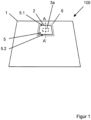
- Figure 1 shows a plan view of a pane arrangement 100 according to the invention.
- a housing 6, a radiation receiver 3a and a region 2, which is defined by the beam path 5 through the pane 1, are arranged in the upper region of the pane 1.
- the beam path 5 has an upper edge 5.1 and a lower edge 5.2.
- FIG 2 shows a simplified, schematic representation of a cross section along the section line AA' from Figure 1 .
- the housing 6 is arranged on the inner side II of the pane 1.
- the inner side II is the side of the pane 1 facing the vehicle interior.
- a radiation receiver 3a is arranged inside the housing 6 and below the pane 1.
- the beam path 5 of the radiation receiver 3a runs in a funnel shape from the exit lens of the radiation receiver 3a through the pane 1.
- the beam path 5 of the field of view penetrates the pane 1 in an area 2 which lies between the upper edge 5.1 of the beam path 5 and the lower edge 5.2 of the beam path 5.
- the area 2 must be sufficiently transparent for the electromagnetic radiation 15 of the radiation receiver 3a.
- a stray light shield 4 is arranged below the radiation receiver 3a.
- the stray light shield 4 extends from the radiation receiver 3a to the pane 1.
- the stray light shield 4 is arranged outside and in particular below the beam path 5 of the radiation receiver 3a in order not to restrict the beam path 5.
- the stray light shield 4 borders on the area 2 of the pane 1 at an angle ⁇ of, for example, 30°.
- the lens hood 4 has an electrically heatable surface 7 on the surface 20.
- the electrically heatable surface 7 can be heated directly, for example by a heating conductor on the surface 20.
- the electrically heatable surface 7 can also be heated indirectly, for example by an electrical heating element in another area of the lens hood 4, wherein the electrically heatable surface 7 is heated by the heat conduction of the material of the lens hood 4.
- the electrically heatable surface 7 is arranged opposite the area 2 of the window 1. If the electrically heatable surface 7 is heated, it heats the area 2 of the window 1 using heat radiation 9 and thereby removes any condensation. For this purpose, it is particularly advantageous if the area 2 and the electrically heatable surface 7 run as parallel as possible so that the heat radiation 9 emanating from the electrically heatable surface 7 hits the area 2 of the window 1 as perpendicularly as possible. At the same time, this would require a very large installation space, which, if arranged on a vehicle window, would extend undesirably far into the interior. Therefore, a certain angle ⁇ of 5° to 45° and, for example, 30° is preferred.
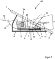
- FIG 3 shows a cross section through a pane arrangement 100 according to the invention in the area of a housing 6.
- the cross section runs along the section line AA' from Figure 1 .
- the housing 6 is arranged on the inner side II of a pane 1 and is attached to the pane 1 by bonding with an acrylate adhesive.
- the pane 1 is, for example, a windshield of a motor vehicle and, for example, a laminated safety glass.
- the inner side II is the side of the pane 1 facing the vehicle interior.
- the housing contains, for example, polybutylene terephthalate with a 10% proportion of glass fibers (PBT-GF10) and was manufactured by an injection molding process.
- PBT-GF10 polybutylene terephthalate with a 10% proportion of glass fibers
- a radiation receiver 3a is arranged inside the housing 6 and underneath the pane 1.
- the radiation receiver 3a is, for example, an infrared camera for a night driving assistance system.
- the radiation receiver 3a detects in particular infrared electromagnetic radiation 15 in the wavelength range from 800 to 1100 nm.
- the field of view of the radiation receiver 3a is aligned to capture images of the traffic area in front of the vehicle.
- the beam path 5 of the field of view runs in a funnel shape from the exit lens of the radiation receiver 3a through the pane 1.
- the beam path 5 of the field of view penetrates the pane 1 in an area 2.
- the area 2 must be sufficiently transparent for the infrared electromagnetic radiation 15 of the radiation receiver 3a.
- the pane 1 has, for example, a transparency for infrared radiation in the wavelength range from 800 nm to 1100 nm of more than 70%.
- the radiation receiver 3a is connected via supply lines 13 to an evaluation electronics not shown here.
- a lens hood 4 is arranged below the radiation receiver 3a. Below here means, in the case of a vehicle window in the installed state, perpendicular and closer to the underside of the vehicle.
- the lens hood 4 extends from the radiation receiver 3a to the window 1.
- the lens hood 4 is arranged below the beam path 5 of the radiation receiver 3a in order not to restrict the field of view of the traffic area.
- the lens hood 4 borders on the area 2 of the window 1 at an angle ⁇ of, for example, 30°.
- the lens hood 4 is made of aluminum with a thermal conductivity of 200 W/(m K), for example.
- the lens hood 4 is black anodized on the surface 20 visible from the outside through the pane 1.
- the surface 20 has a zigzag or wave-shaped structure 10. This reduces or prevents unwanted reflections of scattered light entering the radiation receiver 3a from the side.
- the lens hood 4 has an electrically heatable surface 7 on the surface 20.
- the surface 7 is heated by an electrical heating element 11 on the underside of the lens hood 4.
- the base area of the electrically heatable surface 7 of the lens hood 4 is, for example, 35 cm 2 .
- the electrical heating element 11 is, for example, a heating wire or an electrically conductive coating and can be heated by an electrical current.
- the heating element 11 is connected to a voltage source via supply lines 12, for example to the on-board network of a motor vehicle.
- the electrical heating element 11 If the electrical heating element 11 is heated by an electric current, the electrically heatable area 7 of the surface 20 of the lens hood 4 heats up due to the high thermal conductivity of the material of the lens hood 4.
- the heated area 7 is particularly suitable for heating the area 2 of the window 1 by means of thermal radiation 9 and thereby removing fog. As investigations by the inventors have shown, a heating output of 6 W/dm 2 is sufficient to keep the inside II of the window 1 of a motor vehicle in area 2 free of fog at an outside temperature of 0°C.
- FIG 4 shows a cross section of an alternative embodiment of a disc arrangement 100 according to the invention.
- the disc arrangement 100 corresponds to the disc arrangement 100 of Figure 1
- a radiation source 3b is arranged within the housing 6.
- the radiation source 3b contains, for example, ten red light-emitting diodes and serves as a so-called third brake light on the rear window of a motor vehicle.
- the housing 6 is arranged, for example, in an upper area of the window 1 that has no printed or other heating structures.
- the electromagnetic radiation 15 of the radiation source 3b penetrates the window 1 in an area 2.
- the heat radiation 9, which emanates from the electrically heatable surface 7 of the lens hood 4, can keep the area 2 free of fogging. Furthermore, the heat radiation accelerates defrosting of the outside I of the window 1 above the area 2.
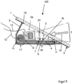
- FIG. 5 shows a plan view of a further embodiment of a pane arrangement 100 according to the invention.
- An infrared-reflecting, low-emissivity coating 16 based on indium tin oxide is arranged on the inner side II of the pane 1.
- Such infrared-reflecting coatings 16 are made, for example, from WO 2011/088330 A2 known.
- the coating 16 has a transparency for electromagnetic radiation in the visible range of about 80%, but absorbs a large proportion of infrared electromagnetic radiation.
- the coating 16 is stripped within the housing 6 and in particular in the area 2 of the beam path 5 of the radiation receiver 3a. The stripping allows a large part of the infrared radiation 15 to reach the radiation receiver 3a. Due to the housing 6 on the inner side II of the pane 1, the stripped area is hardly visible from the outside and the aesthetic aspect of the pane 1 is retained.
- the heating element 11 is arranged in an area 17 of the lens cover 4 that is remote from the panel 1.
- the heating element 11 is, for example, a cost-effective and easy-to-process heating cartridge that has been pressed into an opening in the aluminum body of the lens cover 4.
- the heat generated in the heating element 11 is passed on to the area 18 and the surface 7 due to the good thermal conductivity of the aluminum.
- a thermal insulation 8 is arranged between the radiation receiver 3a and the scattered light shield 4.
- the thermal insulation 8 contains, for example, a polymer and in particular the material of the housing 6.
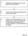
- Figure 6a and 6b each show a flow chart of a method according to the invention for producing a pane arrangement 100 according to the invention.
- the present invention has a number of advantages over prior art pane arrangements.
- the pane In prior art pane arrangements with radiation receivers or radiation sources, the pane is usually heated in the vicinity of the area through which the electromagnetic pane is transmitted. Since no heating conductors should cross this area, the heating conductors are arranged on the outer edge of the area. The interior of the area is heated only by heat conduction. Since glass is a poor heat conductor, the area is heated very inhomogeneously and insufficiently. This type of heating of the area does not produce a satisfactory result.
- the area 2 is heated directly by heat radiation 9.
- the transfer of sufficient heat output occurs solely due to heat radiation. This allows a uniform energy input to the area to be heated. At the same time, it is possible to keep the necessary energy consumption low.
- the electrically heatable lens hood 4 according to the invention can be easily integrated into an existing housing 6 of a camera or a third brake light and replaces, for example, an existing, non-heatable lens hood.
- the power supply of the lens hood 4 according to the invention can simply be provided via the power supply of the camera or the brake light.
Landscapes
- Engineering & Computer Science (AREA)
- Mechanical Engineering (AREA)
- Surface Heating Bodies (AREA)
- Joining Of Glass To Other Materials (AREA)
- Fittings On The Vehicle Exterior For Carrying Loads, And Devices For Holding Or Mounting Articles (AREA)
- Cookers (AREA)
- Heating, Cooling, Or Curing Plastics Or The Like In General (AREA)
Description
- Die Erfindung bezieht sich auf eine Scheibenanordnung mit elektrisch beheizbarer Streulichtblende, insbesondere zum Beheizen eines optisch transparenten Scheibenbereichs mittels Strahlungswärme, ein Verfahren zu deren Herstellung und deren Verwendung.
- Viele Fahrzeuge, Flugzeuge, Hubschrauber und Schiffe sind mit verschiedenen optischen Sensoren ausgestattet. Beispiele für optische Sensoren sind Kamerasysteme, wie Videokameras, Nachtsichtkameras, Restlichtverstärker oder passive Infrarotdetektoren wie FLIR (Forward Looking Infrared). Die Kamerasysteme können Licht im ultravioletten (UV), sichtbaren (VIS) und infraroten Wellenlängenbereich (IR) nutzen. Mit den Kamerasystemen lassen sich auch bei schlechten Witterungsverhältnissen, wie Dunkelheit und Nebel, Gegenstände, Fahrzeuge sowie Personen präzise erkennen. Diese Kamerasysteme können in Kraftfahrzeugen hinter der Windschutzscheibe im Fahrgastraum angeordnet werden. Damit bieten sie auch im Straßenverkehr die Möglichkeit, Gefahrensituationen und Hindernisse rechtzeitig zu erkennen.
- Weitere Einsatzbereiche für optische Sensoren liegen in der elektronischen Distanzmessung (EDM), beispielsweise mit Hilfe von Laserentfernungsmessern. Hierbei kann die Entfernung zu anderen Fahrzeugen bestimmt werden. Derartige Systeme sind im militärischen Anwendungsbereich weit verbreitet, aber auch im zivilen Bereich ergeben sich viele Anwendungsmöglichkeiten. Durch Abstandsmessungen zum vorausfahrenden Fahrzeug lässt sich der notwendige Sicherheitsabstand bestimmen und die Verkehrssicherheit deutlich erhöhen.
- Aufgrund ihrer Empfindlichkeit gegenüber Witterungseinflüssen oder Fahrtwinden müssen derartige Sensoren aber in allen Fällen durch entsprechende Scheiben geschützt werden. Der Sensor kann entweder innerhalb eines Fahrzeuges angebracht sein oder außerhalb wie bei Wärmebildkameras von Hubschraubern. Hierbei ist der Sensor in einem schwenkbaren Gehäuse außen am Hubschrauber angebracht. Um eine optimale Funktion der optischen Sensoren zu gewährleisten, sind bei beiden Möglichkeiten saubere und beschlagsfreie Scheiben zwingend notwendig.
- Gleiches gilt für Strahlungsquellen, die auf der Innenseite von Fahrzeugverglasungen angeordnet sind. Derartige Strahlungsquellen sind beispielsweise optische Leuchtelementen, wie eine dritte Bremsleuchte hinter einer Heckscheibe. Die optischen Leuchtelemente durchleuchten einen Scheibenbereich, der aus ästhetischen und praktischen Gründen üblicherweise nicht durch Heizleiter beheizt wird. Dies ist beispielsweise der Fall, wenn dieser Bereich der Scheibe für Antennen, die nicht mit dem Heizfeld verbunden sind, genutzt wird.
- Beschlag und Vereisungen behindern die Funktionsweise der Sensoren und Lichtquellen, da sie die Transmission elektromagnetischer Strahlung deutlich reduzieren. Während für Wassertropfen und Schmutzpartikel Wischersysteme eingesetzt werden können, reichen diese in der Regel bei Vereisung nicht aus. Hierbei sind Systeme notwendig, die das dem Sensor oder der Lichtquelle zugeordnete Scheibensegment bei Bedarf zumindest kurzzeitig aufheizen und damit einen unterbrechungsfreien Einsatz ermöglichen.
- Neben der äußeren Scheibenoberfläche muss vor allem die innen liegende Scheibe beschlagsfrei gehalten werden. Damit keine Schmutz- und Staubpartikel den Sensor oder die Lichtquelle verschmutzen, wird die Anordnung aus Sensor oder Lichtquelle und Scheibe in der Regel eingekapselt. Dringt in diesen eingekapselten Raum Feuchtigkeit ein, so kann diese Feuchtigkeit vor allem bei kalten Außentemperaturen an der Scheibeninnenseite kondensieren und die Transmission durch den Scheibenbereich einschränken.
-
DE 101 56 850 A1 offenbart einen Sensor in einer Fahrzeugfensterscheibe, dessen Linse vom Fahrzeuginnenraum durch eine Einhausung abgeschlossen ist. Dieser Aufbau verhindert die Ablagerung von Staubpartikeln auf der Linse. Zum Luftaustausch ist ein Partikelfilter vorgesehen. -
DE 10 2004 054 161 A1 offenbart einen Infrarotlicht-Erfassungsbereich in einer Fahrzeugwindschutzscheibe. Der Infrarotlicht-Erfassungsbereich ist von Heizelementen umgeben, die diesen durch Wärmeleitung eis- und beschlagsfrei halten. -
EP 1 605 729 A2 offenbart eine elektrisch beheizbare Scheibe mit einem Kamerafenster. Dieses Kamerafenster wird über eine Heizvorrichtung beschlags- und eisfrei gehalten. Das Heizelement wird an der Position des Kamerafensters in die Scheibe einlaminiert. Zusätzlich kann an der Scheibenoberfläche noch ein zusätzliches Heizelement angebracht werden. Das zusätzliche Heizelement wird bevorzugt als leitfähige Paste auf die Scheibenoberfläche gedruckt. -
US 2011/0204037 A1 offenbart eine Heizvorrichtung für den Bereich der Scheibenwischerruhestellung von Windschutzscheiben. Die Erwärmung dieses Bereiches der Windschutzscheibe wird dabei durch direkten Kontakt der Windschutzscheibe mit dem Heizelement oder durch Ventile mit warmer Luft erzeugt.WO 2004/020250 A1 offenbart ein Verfahren und eine Vorrichtung zur Befestigung eines Sensors an einer Fahrzeugscheibe. -
JP2002341432 A - Die Aufgabe der Erfindung liegt darin, eine verbesserte Scheibenanordnung mit einer beheizbaren Streulichtblende bereitzustellen, welche es ermöglicht einen Bereich einer Scheibe zu beheizen und einfach und kostengünstig aus fertigen, standardmäßigen Scheiben ohne größere Umbaumaßnahmen herstellbar ist.
- Die Aufgabe der vorliegenden Erfindung wird erfindungsgemäß durch eine Scheibenanordnung mit elektrisch beheizbarer Streulichtblende gemäß dem unabhängigen Anspruch 1 gelöst. Des Weiteren umfasst die Erfindung ein Verfahren zu deren Herstellung und deren Verwendung nach den unabhängigen Ansprüchen 12 und 13. Bevorzugte Ausführungen gehen aus den Unteransprüchen hervor.
- Die erfindungsgemäße Scheibenanordnung umfasst mindestens:
- eine Scheibe mit einer Einhausung auf der Innenseite der Scheibe,
- einen Strahlungsempfänger, der innerhalb der Einhausung so der Scheibe zugewandt ist, dass ein Strahlengang einer elektromagnetischen Strahlung durch einen vorgegebenen Bereich der Scheibe führt,
- eine Streulichtblende, die innerhalb der Einhausung und unterhalb des Strahlengangs angeordnet ist und
- eine elektrisch beheizbare Fläche in der Streulichtblende, die den Bereich beheizt.
- Eine alternative erfindungsgemäße Scheibenanordnung umfasst mindestens:
- eine Scheibe mit einer Einhausung auf der Innenseite der Scheibe,
- eine Strahlungsquelle, die innerhalb der Einhausung so der Scheibe zugewandt ist, dass ein Strahlengang einer elektromagnetischen Strahlung durch einen vorgegebenen Bereich der Scheibe führt,
- eine Streulichtblende, die innerhalb der Einhausung und unterhalb des Strahlengangs angeordnet ist und
- eine elektrisch beheizbare Fläche in der Streulichtblende, die den Bereich beheizt.
- Wird die elektrisch beheizbare Fläche beheizt, so strahlt sie Wärmestrahlung ab und beheizt durch die Wärmestrahlung den vorgegebenen Bereich der Scheibe. Dazu ist es notwendig, dass der Strahlengang des Strahlungsempfängers oder der Strahlungsquelle zwischen dem vorgegebenen Bereich der Scheibe und der Streulichtblende verläuft, damit der Strahlengang nicht behindert oder eingeschränkt wird.
- Die Scheibenanordnung umfasst mindestens eine Scheibe und mindestens einen vorgegebenen Bereich der Scheibe. Der vorgegebene Bereich muss transparent sein für die elektromagnetischen Informationen oder Signale, die vom Strahlungsempfänger empfangen werden sollen oder die von der Strahlungsquelle durch den Bereich transmittiert werden sollen. Der Bereich kann ein beliebiger Teil der Scheibe oder ein eingesetztes Scheibensegment sein, das für die entsprechenden optischen und elektromagnetischen Signale eine hohe Transmission aufweist. Das Merkmal "transparent" bezieht sich im Rahmen der Erfindung auf die Transparenz im für den Strahlungsempfänger oder die Strahlungsquelle relevanten Wellenlängenbereich. Für Strahlungsempfänger oder Strahlungsquellen im sichtbaren Bereich und/oder im Infrarotbereich beträgt die Transmission für Wellenlängen von 200 nm bis 2000 nm bevorzugt mehr als 60 %, besonders bevorzugt > 70 % und insbesondere > 90 %. Für Strahlungsempfänger oder Strahlungsquellen im Infrarotbereich beträgt die Transmission im Wellenlängenbereich von 800 nm bis 1300 nm, bevorzugt mehr als 60 %, besonders bevorzugt > 70 % und insbesondere > 90 %. Der Bereich nimmt bevorzugt weniger als 10 %, besonders bevorzugt weniger als 5 % der Scheibenoberfläche ein.
- Der erfindungsgemäße Strahlungsempfänger ist beispielsweise eine Kamera oder ein lichtempfindlicher Sensor, der infrarote, sichtbare und/oder ultraviolette elektromagnetische Strahlung detektieren kann. Der Strahlungsempfänger umfasst bevorzugt Kameras für sichtbares Licht der Wellenlängen von 400 nm bis 800 nm und/oder infrarotes Licht der Wellenlängen von 800 nm bis 1300 nm.
- Die erfindungsgemäße Strahlungsquelle ist bevorzugt eine Lichtquelle, beispielsweise mindestens eine Glühbirne oder eine Leuchtdiode, die infrarote, sichtbare und/oder ultraviolette elektromagnetische Strahlung emittieren kann.
- Die Einhausung schützt den Strahlungsempfänger oder die Strahlungsquelle vor Schmutz- und Staubpartikeln sowie unerwünschten Lichteinfall. Die Einhausung ist bevorzugt im oberen Scheibenbereich angeordnet, bevorzugt nicht mehr als 30 % der Scheibenhöhe vom oberen und/oder unteren Rand entfernt. Die Einhausung enthält bevorzugt ein Polymer, besonders bevorzugt Polybutylenterephthalat, Polyamide, Polycarbonat, Polyurethane, Polybutylen, Polypropylen, Polyethylen, Polyethylenterephthalat, Polyvinylchlorid, Polystyrol, Acrylnitril-Butadien-Styrol, Ethylenvinylacetat, Ethylenvinylalkohol, Polyimide, Polyester, Polyketone, Polyetheretherketone und/oder Polymethylmethacrylat sowie Gemische, Blockpolymere und Copolymere davon.
- Die Scheibe enthält bevorzugt Glas und/oder Polymere, bevorzugt Flachglas, Floatglas, Quarzglas, Borosilikatglas, Kalk-Natron-Glas, Polymethylmethacrylat, Polycarbonat und/oder Gemische oder Schichtverbünde davon. Die Scheibe umfasst bevorzugt Einscheibensicherheitsglas (ESG) oder Verbundscheibensicherheitsglas (VSG).
- Der vorgegebene Bereich weist bevorzugt einen opaken und/oder farbigen Rand auf. Der Rand kann sowohl als Randstreifen oder auch als Randbereich ausgebildet sein.
- Die erfindungsgemäße Streulichtblende weist eine elektrisch beheizbare Fläche auf. Die Streulichtblende ist dabei so angeordnet, dass sich der Strahlengang der elektromagnetischen Strahlung, die der Strahlungsempfänger empfängt beziehungsweise die die Strahlungsquelle emittiert, zwischen der Streulichtblende und der Scheibe befindet. Dies bezieht sich insbesondere auf den Teil des Strahlengangs, der innerhalb der Einhausung verläuft. Die elektrisch beheizbare Fläche kann ein eigenes Bauelement sein, das beispielsweise mit der Streulichtblende verbunden ist, beispielsweise verklebt, verlötet, verpresst oder verschweißt. Die elektrisch beheizbare Fläche kann auch ein Bereich des Materials der Streulichtblende sein.
- Es ist besonders vorteilhaft, wenn der vorgegebene Bereich und die elektrisch beheizbare Fläche möglichst parallel verlaufen, so dass die Wärmestrahlung, die von der elektrisch beheizbaren Fläche ausgeht, möglichst senkrecht auf den Bereich der Scheibe auftrifft. Des Weiteren ist es vorteilhaft, wenn keine weiteren Bauelemente oder Teile der Einhausung die Wärmestrahlung abschirmen können.
- Sind die beheizbare Fläche der Streulichtblende und der vorgegebene Bereich der Scheibe, durch den der Strahlengang verläuft, parallel angeordnet, wird dadurch ein sehr großer Bauraum benötigt, der im Falle einer Anordnung an einer Fahrzeugscheibe unerwünscht weit in den Innenraum ragt. In einer vorteilhaften Ausgestaltung der Erfindung beträgt der Winkel α zwischen dem vorgegebene Bereich und der Streulichtblende von 5° bis 65° und bevorzugt von 10° bis 45°. Dadurch wird eine flachere Anordnung der Streulichtblende an der Scheibe ermöglicht.
- Die elektrisch beheizbare Fläche der Streulichtblende hat vorteilhafterweise eine Grundfläche von 20 cm2 bis 300 cm2, bevorzugt von 20 cm2 bis 40 cm2 für Anordnungen an einer Windschutzscheibe und von 100 cm2 bis 300 cm2 für Heckscheiben von Fahrzeugen. Die Grundfläche ist bevorzugt trapezförmig, wobei die größere der beiden parallelen Seiten unmittelbar benachbart zur Scheibe angeordnet ist.
- In einer vorteilhaften Ausgestaltung der Erfindung wird die Heizleistung der elektrisch beheizbaren Fläche so gewählt, dass sie eine Temperatur von 30° C bis 90°C, bevorzugt 50°C bis 70°C aufweist. Dafür wird erfindungsgemäß eine Heizleistung von 0,5 W/dm2 bis 10 W/dm2 benötigt. Eine derartige Heizleistung ist ausreichend um die Innenseite der Scheibe im vorgegebenen Bereich unter den Standardbedingungen der Kraftfahrzeugtechnik mittels Strahlungswärme von Beschlag zu befreien.
- In einer weiteren vorteilhaften Ausgestaltung der Erfindung weist die elektrisch beheizbare Fläche eine Strahlungsleistung von 0,5 W/dm2 bis 5 W/dm2 auf. Eine derartige Strahlungsleistung ist ausreichend um die Innenseite der Scheibe im vorgegebenen Bereich unter den Standardbedingungen der Kraftfahrzeugtechnik mittels Strahlungswärme von Beschlag zu befreien.
- Eine erfindungsgemäße Streulichtblende weist vorteilhafterweise eine Wärmeleitfähigkeit von mehr als 80 W/(m K), bevorzugt mehr als 190 W/(m K), besonders bevorzugt mehr als 300 W/(m K) auf. Die Oberfläche der Streulichtblende hat vorteilhafterweise eine Emissivität von 0,7 bis 0,97. Dazu enthält die erfindungsgemäße Streulichtblende ein Metall, bevorzugt Aluminium, Kupfer, Federbronze und/oder Stahl oder besteht daraus. Streulichtblenden aus Aluminium können beispielsweise als Meterware als Strangguss gefertigt werden. Streulichtblenden aus Kupfer werden vorzugsweise aus massiven Kupferplatten gepresst oder gestanzt.
- Insbesondere besteht die Streulichtblende aus Aluminium, dessen zur Scheibe weisende Oberfläche schwarz eloxiert wurde. Dies hat den besonderen Vorteil, dass Streulicht, welches von außen durch die Scheibe in die Einhausung eintritt, nicht in den Strahlungsempfänger reflektiert wird und deshalb keine Störsignale hervorruft.
In einer vorteilhaften Ausgestaltung ist die Streulichtblende auf der zur Scheibe weisenden Oberfläche und insbesondere auf der zum Strahlengang zugewandten Seite strukturiert. Die Strukturierung ist beispielsweise eine Riffelung oder eine zickzackförmige oder wellenförmige Ausprägung. Dies hat den besonderen Vorteil, dass Streulicht möglichst nicht in den Strahlungsempfänger reflektiert wird. - Die erfindungsgemäße Streulichtblende kann vorteilhafterweise eine beheizbare Beschichtung und/oder Heizdrähte enthalten. Die Beschichtung oder die Heizdrähte enthalten bevorzugt Fluor-dotiertes Zinndioxid (F:SnO2), Zinn dotiertes Indiumoxid (ITO), Silber, Kupfer, Zinn, Gold, Aluminium, Eisen, Wolfram, Chrom oder Legierungen davon und/oder mindestens ein elektrisch leitfähiges organisches Polymer. Die beheizbare Beschichtung weist bevorzugt eine Schichtdicke von 0,1 µm bis 50 µm, besonders bevorzugt 1 µm bis 10 µm auf.
- Die erfindungsgemäße Streulichtblende enthält in einem ersten Bereich, außerhalb der elektrisch beheizbaren Fläche, ein Heizelement, bevorzugt eine Heizpatrone. Derartige Heizpatronen sind besonders kostengünstig und einfach zu verarbeiten. Aufgrund der hohen Wärmeleitfähigkeit des Materials der Streulichtblende wird die gesamte Streulichtblende erwärmt. Dies führt zu einer indirekten Erwärmung der beheizbaren Fläche und wiederum zu einer Strahlungsheizung des Bereichs.
- Die Einhausung ist vorteilhafterweise mit der Scheibe durch einen Klebstoff verbunden. Der Klebstoff enthält bevorzugt Acrylatklebstoffe, Methylmethacrylatklebstoffe, Cyanacrylatklebstoffe, Polyepoxide, Silikonklebstoffe und/oder silanvernetzende Polymerklebstoffe sowie Gemische und/oder Copolymere davon.
- Die Einhausung ist vorteilhafterweise mehrteilig ausgestaltet, wobei ein Halteteil mit der Scheibe durch einen Klebstoff verbunden und eine Abdeckung für Service-Zwecke lösbar mit dem Halteteil verbunden ist.
- Die Einhausung ist bevorzugt im oberen Bereich der Windschutzscheibe und/oder Heckscheibe, besonders bevorzugt hinter einem Abdeckstreifen, einer Sonnenblende und/oder einem Bandfilter angeordnet.
- Die Einhausung enthält bevorzugt wasserabsorbierende Materialien oder Trockenmittel, besonders bevorzugt Kieselgel, CaCl2, Na2SO4, Aktivkohle, Silikate, Bentonite, Zeolithe und/oder Gemische davon. Die Trockenmittel können in die Oberfläche der Einhausung eingearbeitet sein und/oder in offenen Behältnissen in der Einhausung angeordnet sein. Die Trockenmittel sind bevorzugt so angeordnet, dass ein Luft- und Feuchtigkeitsaustausch mit der Luft im Inneren der Einhausung möglich ist, die Materialien aber nicht umherfliegen können und fixiert sind. Dies kann bevorzugt durch Einschließen der Trockenmittel in einen luft- und feuchtigkeitsdurchlässigen Polymerfilm oder in einem feinmaschigen Netz erfolgen.
- Die Erfindung umfasst des Weiteren ein Verfahren zur Herstellung einer Scheibenanordnung mit elektrisch beheizbarer Streulichtblende, wobei
- a. die Einhausung an dem vorgegebenen Bereich der Scheibe befestigt wird,
- b. der Strahlungsempfänger und/oder die Strahlungsquelle in der Einhausung angeordnet wird und
- c. die Streulichtblende in der Einhausung angeordnet wird, wobei der Strahlengang des Strahlungsempfängers und/oder der Strahlungsquelle zwischen Scheibe und Streulichtblende verläuft.
- Die Erfindung umfasst des Weiteren die Verwendung der erfindungsgemäßen Scheibenanordnung in Fahrzeugen, Schiffen, Flugzeugen und Hubschraubern und bevorzugt als Windschutzscheibe und/oder Heckscheibe eines Fahrzeuges.
- Im Folgenden wird die Erfindung anhand einer Zeichnung näher erläutert. Die Zeichnung ist eine schematische Darstellung und nicht maßstabsgetreu. Die Zeichnung schränkt die Erfindung in keiner Weise ein.
- Es zeigen:
-
Figur 1 eine Draufsicht auf ein Ausgestaltungsbeispiel einer erfindungsgemäßen Scheibenanordnung, -
Figur 2 eine vereinfachte, schematische Darstellung eines Querschnitts einer erfindungsgemäßen Scheibenanordnung, -
Figur 3 einen Querschnitt eines Ausschnitts einer erfindungsgemäßen Scheibenanordnung, -
Figur 4 einen Querschnitt eines Ausschnitts einer alternativen Ausgestaltung einer erfindungsgemäßen Scheibenanordnung, -
Figur 5 einen Querschnitt einer erfindungsgemäßen Scheibenanordnung, -
Figur 6a ein Flussdiagramm einer bevorzugten Ausführungsform des erfindungsgemäßen Verfahrens und -
Figur 6b ein Flussdiagramm einer alternativen Ausführungsform des erfindungsgemäßen Verfahrens. -
Figur 1 zeigt eine Draufsicht auf eine erfindungsgemäße Scheibenanordnung 100. Eine Einhausung 6, ein Strahlungsempfänger 3a und einen Bereich 2, der durch den Strahlengang 5 durch die Scheibe 1 vorgegeben wird, sind im oberen Bereich der Scheibe 1 angeordnet. Der Strahlengang 5 hat einen oberen Rand 5.1 und einen unteren Rand 5.2. -
Figur 2 zeigt eine vereinfachte, schematische Darstellung eines Querschnitts entlang der Schnittlinie A-A' ausFigur 1 . Die Einhausung 6 ist an der Innenseite II der Scheibe 1 angeordnet. Im Falle einer Fahrzeugscheibe ist die Innenseite II die dem Fahrzeuginnenraum zugewandte Seite der Scheibe 1.
Innerhalb der Einhausung 6 und unterhalb der Scheibe 1 ist ein Strahlungsempfänger 3a angeordnet. Der Strahlengang 5 des Strahlungsempfängers 3a verläuft trichterförmig von der Austrittslinse des Strahlungsempfängers 3a durch die Scheibe 1. Der Strahlengang 5 des Sichtfelds durchdringt die Scheibe 1 in einem Bereich 2, der zwischen dem oberen Rand 5.1 des Strahlengangs 5 und dem unteren Rand 5.2 des Strahlengangs 5 liegt. Der Bereich 2 muss ausreichend transparent für die elektromagnetische Strahlung 15 des Strahlungsempfängers 3a sein. - Unterhalb des Strahlungsempfängers 3a ist eine Streulichtblende 4 angeordnet. Die Streulichtblende 4 reicht vom Strahlungsempfänger 3a bis zur Scheibe 1. Die Streulichtblende 4 ist außerhalb und insbesondere unterhalb des Strahlengangs 5 des Strahlungsempfängers 3a angeordnet, um nicht den Strahlengang 5 einzuschränken. Die Streulichtblende 4 grenzt an den Bereich 2 der Scheibe 1 unter einem Winkel α von beispielsweise 30°.
- Die Streulichtblende 4 weist an der Oberfläche 20 eine elektrisch beheizbare Fläche 7 auf. Die elektrisch beheizbare Fläche 7 kann unmittelbar beheizt werden, beispielsweise durch einen Heizleiter an der Oberfläche 20. Die elektrisch beheizbare Fläche 7 kann auch indirekt beheizt werden, beispielsweise durch ein elektrisches Heizelement in einem anderen Bereich der Streulichtblende 4, wobei die elektrisch beheizbare Fläche 7 durch die Wärmeleitung des Materials der Streulichtblende 4 erwärmt wird.
- Die elektrisch beheizbare Fläche 7 ist gegenüberliegend zum Bereich 2 der Scheibe 1 angeordnet. Ist die elektrisch beheizbare Fläche 7 beheizt, so heizt sie den Bereich 2 der Scheibe 1 durch Wärmestrahlung 9 auf und befreit ihn dadurch von Beschlag. Dazu ist es besonders vorteilhaft, wenn der Bereich 2 und die elektrisch beheizbare Fläche 7 möglichst parallel verlaufen, so dass die Wärmestrahlung 9, die von der elektrisch beheizbaren Fläche 7 ausgeht, möglichst senkrecht auf den Bereich 2 der Scheibe 1 auftrifft. Gleichzeitig würde dadurch ein sehr großer Bauraum benötigt werden, der im Falle einer Anordnung an einer Fahrzeugscheibe unerwünscht weit in den Innenraum ragen würde. Deshalb ist ein gewisser Winkel α von 5° bis 45° und beispielsweise 30° bevorzugt.
-
Figur 3 zeigt einen Querschnitt durch eine erfindungsgemäße Scheibenanordnung 100 im Bereich einer Einhausung 6. Der Querschnitt verläuft entlang der Schnittlinie A-A' ausFigur 1 . Die Einhausung 6 ist an der Innenseite II einer Scheibe 1 angeordnet und durch Verkleben mit einem Acrylatklebstoff an der Scheibe 1 befestigt. Die Scheibe 1 ist beispielsweise eine Windschutzscheibe eines Kraftfahrzeugs und beispielsweise ein Verbundsicherheitsglas. Die Innenseite II ist die dem Fahrzeuginnenraum zugewandte Seite der Scheibe 1. Die Einhausung enthält beispielsweise Polybutylenterephthalat mit einem 10%-igen Anteil an Glasfasern (PBT-GF10) und wurde durch ein Spritzgußverfahren hergestellt. - Innerhalb der Einhausung 6 und unterhalb der Scheibe 1 ist ein Strahlungsempfänger 3a angeordnet. Der Strahlungsempfänger 3a ist beispielsweise eine Infrarotkamera für ein Nachtfahrassistenzsystem. Der Strahlungsempfänger 3a detektiert insbesondere infrarote elektromagnetische Strahlung 15 im Wellenlängenbereich von 800 bis 1100 nm. Das Sichtfeld des Strahlungsempfängers 3a ist zur Bilderfassung des vor dem Fahrzeug befindlichen Verkehrsraumes ausgerichtet. Der Strahlengang 5 des Sichtfelds verläuft trichterförmig von der Austrittslinse des Strahlungsempfängers 3a durch die Scheibe 1. Der Strahlengang 5 des Sichtfelds durchdringt die Scheibe 1 in einem Bereich 2. Der Bereich 2 muss ausreichend transparent für die infrarote elektromagnetische Strahlung 15 des Strahlungsempfängers 3a sein. Die Scheibe 1 hat im Bereich 2 beispielsweise eine Transparenz für Infrarotstrahlung im Wellenlängenbereich von 800 nm bis 1100 nm von mehr als 70%. Der Strahlungsempfänger 3a ist über Zuleitungen 13 mit einer hier nicht dargestellten Auswerteelektronik verbunden.
- Unterhalb des Strahlungsempfängers 3a ist eine Streulichtblende 4 angeordnet. Unterhalb bedeutet hier im Falle einer Fahrzeugscheibe in eingebautem Zustand, lotrecht und näher zur Unterseite des Fahrzeugs. Die Streulichtblende 4 reicht vom Strahlungsempfänger 3a bis zur Scheibe 1. Die Streulichtblende 4 ist unterhalb des Strahlengangs 5 des Strahlungsempfängers 3a angeordnet, um nicht das Sichtfeld auf den Verkehrsraum einzuschränken. Die Streulichtblende 4 grenzt an den Bereich 2 der Scheibe 1 unter einem Winkel α von beispielsweise 30°.
- Die Streulichtblende 4 besteht beispielsweise aus Aluminium mit einer Wärmeleitfähigkeit von 200 W/(m K). Die Streulichtblende 4 ist auf der von außen, durch die Scheibe 1 sichtbaren Oberfläche 20 schwarz eloxiert. Des Weiteren weist die Oberfläche 20 eine zickzackförmige oder wellenförmige Strukturierung 10 auf. Dadurch werden unerwünschte Reflexionen von seitlich eintreffendem Streulicht in den Strahlungsempfänger 3a reduziert oder verhindert.
- Die Streulichtblende 4 weist an der Oberfläche 20 eine elektrisch beheizbare Fläche 7 auf. Im dargestellten Beispiel erfolgt die Beheizung der Fläche 7 durch ein elektrisches Heizelement 11 an der Unterseite der Streulichtblende 4. Die Grundfläche der elektrisch beheizbaren Fläche 7 der Streulichtblende 4 beträgt beispielsweise 35 cm2. Das elektrische Heizelement 11 ist beispielsweise ein Heizdraht oder eine elektrisch leitfähige Beschichtung und kann durch einen elektrischen Strom geheizt werden. Das Heizelement 11 ist über Zuleitungen 12 mit einer Spannungsquelle verbunden, beispielsweise mit dem Bordnetz eines Kraftfahrzeugs.
- Wird das elektrische Heizelement 11 durch einen elektrischen Strom geheizt, erwärmt sich die elektrisch beheizbare Fläche 7 der Oberfläche 20 der Streulichtblende 4 aufgrund der hohen Wärmeleitfähigkeit des Materials der Streulichtblende 4. Die erwärmte Fläche 7 ist insbesondere dazu geeignet, den Bereich 2 der Scheibe 1 durch Wärmestrahlung 9 zu heizen und dadurch von Beschlag zu befreien. Wie Untersuchungen der Erfinder ergaben, genügt eine Heizleistung von 6 W/dm2 um die Innenseite II der Scheibe 1 eines Kraftfahrzeugs im Bereich 2 bei 0°C Außentemperatur beschlagsfrei zu halten.
-
Figur 4 zeigt einen Querschnitt einer alternativen Ausgestaltung einer erfindungsgemäßen Scheibenanordnung 100. Die Scheibenanordnung 100 entspricht der Scheibenanordnung 100 ausFigur 1 . Anstelle des Strahlungsempfängers 3a ist eine Strahlungsquelle 3b innerhalb der Einhausung 6 angeordnet. Die Strahlungsquelle 3b enthält beispielsweise zehn rote Leuchtdioden und dient als sogenannte dritte Bremsleuchte an der Heckscheibe eines Kraftfahrzeugs. Die Einhausung 6 ist beispielsweise in einem oberen Bereich der Scheibe 1 angeordnet, der keine aufgedruckten oder anderweitigen Heizstrukturen aufweist. Die elektromagnetische Strahlung 15 der Strahlungsquelle 3b durchdringt die Scheibe 1 in einem Bereich 2. Durch die Wärmestrahlung 9, die von der elektrisch beheizbaren Fläche 7 der Streulichtblende 4 ausgeht, kann der Bereich 2 beschlagsfrei gehalten werden. Des Weiteren beschleunigt die Wärmestrahlung eine Enteisung der Außenseite I der Scheibe 1 über dem Bereich 2. -
Figur 5 zeigt eine Draufsicht auf ein weiteres Ausgestaltungsbeispiel einer erfindungsgemäßen Scheibenanordnung 100. Auf der Innenseite II der Scheibe 1 ist eine infrarotreflektierende, niedrig emissive Beschichtung 16 auf der Basis von Indiumzinnoxid angeordnet. Derartige infrarotreflektierende Beschichtungen 16 sind beispielsweise ausWO 2011/088330 A2 bekannt. Die Beschichtung 16 hat eine Transparenz für elektromagnetische Strahlung im sichtbaren Bereich von etwa 80 %, absorbiert aber einen großen Anteil von infraroter elektromagnetischer Strahlung. Die Beschichtung 16 ist innerhalb der Einhausung 6 und insbesondere im Bereich 2 des Strahlengangs 5 des Strahlungsempfängers 3a entschichtet. Durch die Entschichtung kann ein Großteil der infraroten Strahlung 15 zum Strahlungsempfänger 3a gelangen. Durch die Einhausung 6 auf der Innenseite II der Scheibe 1 ist der entschichtete Bereich von außen kaum mehr zu erkennen und der ästhetische Aspekt der Scheibe 1 bleibt erhalten. - Im dargestellten Beispiel ist das Heizelement 11 in einem von der Scheibe 1 entfernten Bereich 17 der Streulichtscheibe 4 angeordnet. Das Heizelement 11 ist beispielsweise eine kostengünstige und einfach zu verarbeitende Heizpatrone, die in eine Öffnung des Aluminiumkörpers der Streulichtblende 4 eingepresst wurde. Die im Heizelement 11 erzeugte Wärme wird aufgrund der guten Wärmeleitfähigkeit des Aluminiums an den Bereich 18 und die Fläche 7 weitergeleitet. Die somit indirekt elektrisch beheizte Fläche 7 beheizt über Wärmestrahlung 9 den Bereich 2 der Scheibe 1. Um den Strahlungsempfänger 3a vor zu hohen Temperaturen zu schützen ist zwischen Strahlungsempfänger 3a und Streulichtblende 4 eine thermische Isolierung 8 angeordnet. Die thermische Isolierung 8 enthält beispielsweise ein Polymer und insbesondere das Material der Einhausung 6.
-
Figur 6a und6b zeigen jeweils ein Flussdiagramm eines erfindungsgemäßen Verfahrens zur Herstellung einer erfindungsgemäßen Scheibenanordnung 100. - Die vorliegende Erfindung zeigt eine Reihe von Vorteilen gegenüber Scheibenanordnungen nach dem Stand der Technik. Bei Scheibenanordnungen mit Strahlungsempfängern oder Strahlungsquellen nach dem Stand der Technik wird üblicherweise die Scheibe in der Umgebung des Bereichs, durch den die elektromagnetische Scheibe transmittiert wird, geheizt. Da möglichst keine Heizleiter diesen Bereich durchkreuzen sollen, sind die Heizleiter am äußeren Rande des Bereichs angeordnet. Die Erwärmung des Inneren des Bereichs erfolgt lediglich über Wärmeleitung. Da Glas ein schlechter Wärmeleiter ist, wird der Bereich sehr inhomogen und unzureichend erwärmt. Durch diese Art der Beheizung des Bereichs ist kein befriedigendes Ergebnis zu erzielen.
- Bei der vorliegenden Erfindung wird der Bereich 2 durch Wärmestrahlung 9 direkt geheizt. Die Übertragung einer ausreichenden Heizleistung erfolgt allein aufgrund von Wärmestrahlung. Dies erlaubt einen gleichmäßigen Energieeintrag auf den zu beheizenden Bereich. Gleichzeitig ist es möglich den nötigen Energieverbrauch gering zu halten.
- Die erfindungsgemäße elektrisch beheizbare Streulichtblende 4 ist einfach in eine bereits vorhandene Einhausung 6 einer Kamera oder einer dritten Bremsleuchte zu integrieren und ersetzt dort beispielsweise eine bereits vorhandene, nicht beheizbare Streulichtblende. Die Spannungsversorgung der erfindungsgemäßen Streulichtblende 4 kann einfach über die Spannungsversorgung der Kamera oder der Bremsleuchte erfolgen.
- Es war für den Fachmann unerwartet und überraschend, dass die Übertragung von Wärmestrahlung bei der erfindungsgemäßen Scheibenanordnung ausreichend ist, um den zu beheizenden Bereich beschlagsfrei zu halten.
-
- 1
- Scheibe
- 2
- Bereich
- 3a
- Strahlungsempfänger
- 3b
- Strahlungsquelle
- 4
- Streulichtblende
- 5
- Strahlengang
- 5.1
- oberer Rand des Strahlengangs 5
- 5.2
- unterer Rand des Strahlengangs 5
- 6
- Einhausung
- 7
- beheizbare Fläche
- 8
- thermische Isolierung
- 9
- Wärmestrahlung
- 10
- Strukturierung, Riffelung
- 11
- Heizelement
- 12
- Zuleitung zum Heizelement 7 oder zur Heizfläche 11
- 13
- Zuleitung zum Strahlungsempfänger 3a oder zur Strahlungsquelle 3b
- 15
- elektromagnetische Strahlung
- 16
- Beschichtung
- 17
- erster Bereich der Streulichtblende 4
- 18
- zweiter Bereich der Streulichtblende 4
- 20
- Oberfläche der Streulichtblende 4
- 100
- Scheibenanordnung
- α
- Winkel zwischen Scheibe 1 und Streulichtblende 4
- I
- Außenseite der Scheibe 1
- II
- Innenseite der Scheibe 1
- III
- Seite der Streulichtblende 4
- A-A'
- Schnittlinie
Claims (13)
- Scheibenanordnung (100) mit elektrisch beheizbarer Streulichtblende (4), mindestens umfassend:- eine Scheibe (1) mit einer Einhausung (6) auf der Innenseite (II) der Scheibe (1),- einen Strahlungsempfänger (3a) und/oder eine Strahlungsquelle (3b), der/die innerhalb der Einhausung (6) so der Scheibe (1) zugewandt ist, dass ein Strahlengang (5) einer elektromagnetischen Strahlung (15) durch einen vorgegebenen Bereich (2) der Scheibe (1) führt,gekennzeichnet durch- eine Streulichtblende (4), die innerhalb der Einhausung (6) und unterhalb des Strahlengangs (5) angeordnet ist und- eine elektrisch beheizbare Fläche (7) in der Streulichtblende (4), die Wärmestrahlung abstrahlt und den Bereich (2) allein durch die Wärmestrahlung beheizt,wobei die Streulichtblende (4) außerhalb der elektrisch beheizbaren Fläche (7) ein elektrisches Heizelement (7) aufweist und die elektrisch beheizbare Fläche (7) durch Wärmeleitung beheizbar ist, und wobei die Streulichtblende (4) ein Metall enthält oder daraus besteht,wobei die elektrisch beheizbare Fläche (7) eine Heizleistung von 0,5 W/dm2 bis 10 W/dm2 aufweist.
- Scheibenanordnung (100) nach Anspruch 1, wobei der Strahlungsempfänger (3a) eine Kamera oder einen Photosensor für infrarote, sichtbare und/oder ultraviolette elektromagnetische Strahlung enthält.
- Scheibenanordnung (100) nach Anspruch 1, wobei die Strahlungsquelle (3b) eine Glühbirne oder eine Leuchtdiode für infrarote, sichtbare und/oder ultraviolette elektromagnetische Strahlung enthält.
- Scheibenanordnung (100) nach einem der Ansprüche 1 bis 3, wobei die Streulichtblende (4) Aluminium, Kupfer, Federbronze und/oder Stahl und bevorzugt schwarz eloxiertes Aluminium enthält oder daraus besteht.
- Scheibenanordnung (100) nach einem der Ansprüche 1 bis 4, wobei die Streulichtblende (4) eine Wärmeleitfähigkeit von mehr als 80W/(m K), bevorzugt mehr als 190W/(m K) und besonders bevorzugt mehr als 300 W/(m K) aufweist.
- Scheibenanordnung (100) nach einem der Ansprüche 1 bis 5, wobei das elektrische Heizelement (7) eine Heizpatrone (11) ist.
- Scheibenanordnung (100) nach einem der Ansprüche 1 bis 6, wobei der Winkel (α) zwischen Bereich (2) und elektrisch beheizbarer Fläche (7) von 5° bis 65° und bevorzugt von 10° bis 45° beträgt.
- Scheibenanordnung (100) nach einem der Ansprüche 1 bis 7, wobei der Bereich (2) eine Transparenz für die elektromagnetische Strahlung (15) von > 60 %, bevorzugt > 70 %, besonders bevorzugt > 90 % aufweist.
- Scheibenanordnung (100) nach einem der Ansprüche 1 bis 8, wobei die Streulichtblende (4) auf der dem Strahlengang (5) zugewandten Seite (III) eine Riffelung (10) aufweist.
- Scheibenanordnung (100) nach einem der Ansprüche 1 bis 9, wobei die Scheibe (1) Glas und/oder Polymere, bevorzugt Flachglas, Floatglas, Quarzglas, Borosilikatglas, Kalk-Natron-Glas, Polymethylmethacrylat und/oder Gemische davon enthält.
- Scheibenanordnung (100) nach einem der Ansprüche 1 bis 10, wobei die Einhausung (6) im oberen Bereich der Scheibe (1) angeordnet ist.
- Verfahren zur Herstellung einer Scheibenanordnung (100) mit elektrisch beheizbarer Streulichtblende (4) nach einem der Ansprüche 1 bis 11, wobeia) die Einhausung (6) an dem Bereich (2) der Scheibe (1) befestigt wird,b) der Strahlungsempfänger (3a) und/oder die Strahlungsquelle (3b) in der Einhausung (6) angeordnet wird undc) die Streulichtblende (4) in der Einhausung (6) angeordnet wird, wobei der Strahlengang (5) des Strahlungsempfängers (3a) und/oder der Strahlungsquelle (3b) zwischen Scheibe (1) und Streulichtblende (4) verläuft.
- Verwendung einer Scheibenanordnung (100) mit elektrisch beheizbarer Streulichtblende (4) nach einem der Ansprüche 1 bis 11 in Fahrzeugen, Schiffen, Flugzeugen und Hubschraubern, bevorzugt als Windschutzscheibe und/oder Heckscheibe eines Fahrzeuges.
Priority Applications (3)
| Application Number | Priority Date | Filing Date | Title |
|---|---|---|---|
| PL13703378.3T PL2823689T5 (pl) | 2012-03-05 | 2013-02-06 | Układ szyby z elektrycznie ogrzewaną przysłoną światła rozproszonego |
| EP18188317.4A EP3425999B1 (de) | 2012-03-05 | 2013-02-06 | Scheibenanordnung mit elektrisch beheizbarer streulichtblende |
| EP13703378.3A EP2823689B2 (de) | 2012-03-05 | 2013-02-06 | Scheibenanordnung mit elektrisch beheizbarer streulichtblende |
Applications Claiming Priority (3)
| Application Number | Priority Date | Filing Date | Title |
|---|---|---|---|
| EP12158006 | 2012-03-05 | ||
| PCT/EP2013/052268 WO2013131700A1 (de) | 2012-03-05 | 2013-02-06 | Scheibenanordnung mit elektrisch beheizbarer streulichtblende |
| EP13703378.3A EP2823689B2 (de) | 2012-03-05 | 2013-02-06 | Scheibenanordnung mit elektrisch beheizbarer streulichtblende |
Related Child Applications (3)
| Application Number | Title | Priority Date | Filing Date |
|---|---|---|---|
| EP18188317.4A Division-Into EP3425999B1 (de) | 2012-03-05 | 2013-02-06 | Scheibenanordnung mit elektrisch beheizbarer streulichtblende |
| EP18188317.4A Division EP3425999B1 (de) | 2012-03-05 | 2013-02-06 | Scheibenanordnung mit elektrisch beheizbarer streulichtblende |
| EP18180183.8 Division-Into | 2018-06-27 |
Publications (3)
| Publication Number | Publication Date |
|---|---|
| EP2823689A1 EP2823689A1 (de) | 2015-01-14 |
| EP2823689B1 EP2823689B1 (de) | 2018-10-17 |
| EP2823689B2 true EP2823689B2 (de) | 2025-01-29 |
Family
ID=47681879
Family Applications (2)
| Application Number | Title | Priority Date | Filing Date |
|---|---|---|---|
| EP13703378.3A Active EP2823689B2 (de) | 2012-03-05 | 2013-02-06 | Scheibenanordnung mit elektrisch beheizbarer streulichtblende |
| EP18188317.4A Active EP3425999B1 (de) | 2012-03-05 | 2013-02-06 | Scheibenanordnung mit elektrisch beheizbarer streulichtblende |
Family Applications After (1)
| Application Number | Title | Priority Date | Filing Date |
|---|---|---|---|
| EP18188317.4A Active EP3425999B1 (de) | 2012-03-05 | 2013-02-06 | Scheibenanordnung mit elektrisch beheizbarer streulichtblende |
Country Status (11)
| Country | Link |
|---|---|
| US (2) | US9913319B2 (de) |
| EP (2) | EP2823689B2 (de) |
| JP (2) | JP2015509458A (de) |
| KR (1) | KR101618492B1 (de) |
| CN (1) | CN104160779B (de) |
| DE (1) | DE202013012934U1 (de) |
| ES (1) | ES2706016T5 (de) |
| PL (1) | PL2823689T5 (de) |
| PT (1) | PT2823689T (de) |
| TR (1) | TR201900231T4 (de) |
| WO (1) | WO2013131700A1 (de) |
Families Citing this family (62)
| Publication number | Priority date | Publication date | Assignee | Title |
|---|---|---|---|---|
| DE102014110550B4 (de) | 2014-07-25 | 2017-07-13 | Oventrop Gmbh & Co. Kg | Regelarmatur |
| US10046692B2 (en) * | 2014-08-14 | 2018-08-14 | George A. Van Straten | Heated light enclosure having an adaptable heating system |
| US9395538B2 (en) * | 2014-09-26 | 2016-07-19 | Delphi Technologies, Inc. | Vehicle imager assembly with localized window defogging |
| WO2016085089A1 (en) * | 2014-11-24 | 2016-06-02 | Lg Electronics Inc. | Mobile terminal |
| WO2016105674A1 (en) * | 2014-12-22 | 2016-06-30 | Illinois Tool Works Inc. | Dual plane heater for vehicle sensor system |
| FR3035826B1 (fr) * | 2015-05-07 | 2018-11-16 | Saint-Gobain Glass France | Vitrage de vehicule comprenant une platine pour la fixation de plusieurs accessoires, platine et procede de fixation. |
| JP6304205B2 (ja) * | 2015-11-11 | 2018-04-04 | トヨタ自動車株式会社 | 車載撮像装置 |
| DE102016000269A1 (de) * | 2016-01-14 | 2017-07-20 | K.L. Kaschier- Und Laminier Gmbh | Streulichtblende eines Bilderfassungsgerätes |
| JP6536823B2 (ja) * | 2016-02-29 | 2019-07-03 | トヨタ自動車株式会社 | ウィンドウガラス加熱装置 |
| US20170274832A1 (en) * | 2016-03-24 | 2017-09-28 | Nidec Elesys Corporation | Windshield including vehicle-mounted radar |
| JP6589726B2 (ja) * | 2016-04-06 | 2019-10-16 | トヨタ自動車株式会社 | 車両用撮影装置 |
| JP6555190B2 (ja) * | 2016-05-18 | 2019-08-07 | トヨタ自動車株式会社 | 車両用撮影装置 |
| JP2017222327A (ja) * | 2016-06-17 | 2017-12-21 | トヨタ自動車株式会社 | ウィンドウガラス加熱装置 |
| US10131272B2 (en) * | 2016-07-18 | 2018-11-20 | Ford Global Technologies, Llc | Warning light system with dedicated windshield heating element |
| JP6402866B2 (ja) | 2016-08-29 | 2018-10-10 | トヨタ自動車株式会社 | ウインドウガラス加熱装置 |
| DE102017001513A1 (de) * | 2017-02-17 | 2018-08-23 | K. L. Kaschier- Und Laminier Gmbh | Streulichtblende eines Bilderfassungsgerätes |
| DE102017203720B4 (de) | 2017-03-07 | 2024-10-02 | Bayerische Motoren Werke Aktiengesellschaft | Enteisungsvorrichtung und Verfahren zum Enteisen eines Personenkraftwagens |
| DE102017204975A1 (de) | 2017-03-24 | 2018-09-27 | Bayerische Motoren Werke Aktiengesellschaft | Räumeinrichtung für eine Kraftwagenoberfläche |
| DE102017206438A1 (de) * | 2017-04-13 | 2018-10-18 | Bayerische Motoren Werke Aktiengesellschaft | Steuergerät, Fortbewegungsmittel und Scheibe für ein Fortbewegungsmittel mit Kamera |
| DE102017207024B4 (de) * | 2017-04-26 | 2023-03-30 | Audi Ag | Sensoranordnung für ein Kraftfahrzeug sowie Kraftfahrzeug |
| JP6813431B2 (ja) * | 2017-05-23 | 2021-01-13 | 東京コスモス電機株式会社 | 発熱装置 |
| JP6953181B2 (ja) * | 2017-05-23 | 2021-10-27 | 東京コスモス電機株式会社 | 発熱装置 |
| JP6953180B2 (ja) * | 2017-05-23 | 2021-10-27 | 東京コスモス電機株式会社 | 発熱装置 |
| WO2019014488A2 (en) * | 2017-07-12 | 2019-01-17 | Van Straten George A | HEAT SOURCE FOR VEHICLE LIGHTING ARRANGEMENT AND METHOD |
| EP3466775B1 (de) * | 2017-10-09 | 2020-08-19 | Kautex Textron GmbH & Co. Kg | Teleskopische fahrzeugoberflächenreinigungsvorrichtung |
| JP6852655B2 (ja) * | 2017-11-14 | 2021-03-31 | トヨタ自動車株式会社 | 車両用計測装置 |
| JP7142428B2 (ja) | 2017-11-20 | 2022-09-27 | 株式会社ニフコ | 加熱装置 |
| JP7125261B2 (ja) | 2017-12-12 | 2022-08-24 | 小島プレス工業株式会社 | 車両用撮影装置 |
| JP6939536B2 (ja) * | 2017-12-27 | 2021-09-22 | トヨタ自動車株式会社 | 車両用撮影装置 |
| JP6943177B2 (ja) * | 2017-12-27 | 2021-09-29 | トヨタ自動車株式会社 | 外部情報取得装置 |
| JP7006258B2 (ja) * | 2017-12-27 | 2022-01-24 | トヨタ自動車株式会社 | 車両用撮影装置及び加熱装置 |
| JP6702933B2 (ja) * | 2017-12-28 | 2020-06-03 | 株式会社ニフコ | 車両用ウインド装置の断熱構造 |
| JP2019155946A (ja) * | 2018-03-07 | 2019-09-19 | 株式会社デンソー | 電磁波利用システム |
| JP2019155947A (ja) * | 2018-03-07 | 2019-09-19 | 株式会社デンソー | 車両用電磁波利用システム |
| JP6583651B2 (ja) * | 2018-04-03 | 2019-10-02 | トヨタ自動車株式会社 | 加熱装置 |
| CN113170533B (zh) * | 2018-11-22 | 2023-11-14 | Sabic环球技术有限责任公司 | 用于车辆的外部面板组件 |
| JP7042206B2 (ja) | 2018-12-18 | 2022-03-25 | 本田技研工業株式会社 | 輸送機器およびセンサブラケット |
| JP6726265B2 (ja) | 2018-12-18 | 2020-07-22 | 本田技研工業株式会社 | センサブラケット |
| JP7048479B2 (ja) | 2018-12-18 | 2022-04-05 | 本田技研工業株式会社 | 輸送機器およびセンサブラケット |
| JP7044692B2 (ja) * | 2018-12-20 | 2022-03-30 | 本田技研工業株式会社 | 移動体用撮影システム |
| JP7172682B2 (ja) * | 2019-02-06 | 2022-11-16 | トヨタ自動車株式会社 | カメラ搭載構造 |
| JP7088078B2 (ja) * | 2019-02-27 | 2022-06-21 | トヨタ自動車株式会社 | カメラ搭載構造 |
| JP7066650B2 (ja) * | 2019-03-05 | 2022-05-13 | 本田技研工業株式会社 | 曇り抑制装置およびその制御方法 |
| JP7140698B2 (ja) * | 2019-03-05 | 2022-09-21 | 本田技研工業株式会社 | 曇り抑制装置およびその制御方法 |
| GB201904203D0 (en) | 2019-03-26 | 2019-05-08 | Pikington Group Ltd | Laminated glazing and process |
| WO2020220005A1 (en) | 2019-04-26 | 2020-10-29 | Van Straten Enterprises, Inc. | Heater and electromagnetic illuminator heater |
| CN110091809A (zh) * | 2019-05-29 | 2019-08-06 | 河北科力汽车零部件有限公司 | 一种基于导电塑料的自发热摄像头支架及导电塑料的配方 |
| JP7461121B2 (ja) * | 2019-09-09 | 2024-04-03 | 株式会社クラベ | スクリーンヒーターシステム |
| JP7512046B2 (ja) * | 2020-02-18 | 2024-07-08 | 東京コスモス電機株式会社 | 取付装置 |
| US20230194670A1 (en) * | 2020-05-25 | 2023-06-22 | Agc Glass Europe | Baffle of a detection device for automotive vehicle |
| JP7584941B2 (ja) * | 2020-06-02 | 2024-11-18 | 京セラ株式会社 | カメラモジュール |
| EP4275961A4 (de) * | 2021-01-08 | 2024-12-11 | Agc Inc. | Fahrzeugglas und verfahren zur herstellung eines fahrzeugglases |
| US12121088B2 (en) | 2021-01-21 | 2024-10-22 | Van Straten Enterprises, Inc. | Optical face protection shield, heated optical face protection apparatus, and method |
| FR3121384B1 (fr) * | 2021-03-31 | 2023-03-24 | Saint Gobain | Vitrage de vehicule et dispositif avec systeme de detection proche infrarouge associe |
| EP4323185A1 (de) | 2021-04-12 | 2024-02-21 | Saint-Gobain Glass France | Scheibenanordnung mit beheizbarem sensorfenster |
| US12614122B2 (en) | 2021-12-30 | 2026-04-28 | Y.E. Hub Armenia LLC | Method and a system of determining LiDAR data degradation degree |
| DE102022101566B4 (de) | 2022-01-24 | 2024-01-18 | Webasto SE | Sensoranordnung, umfassend ein Sensormodul und ein Scheibenelement, sowie Fahrzeugdach mit derartiger Sensoranordnung |
| JP7345000B2 (ja) * | 2022-02-04 | 2023-09-14 | 本田技研工業株式会社 | 保持装置および車両 |
| CN121666308A (zh) | 2023-08-10 | 2026-03-13 | 法国圣戈班安全玻璃公司 | 具有传感器窗的层压片材布置 |
| US20250305885A1 (en) * | 2024-03-29 | 2025-10-02 | Lynred | Infrared camera and outer window assembly for a vehicle glazing |
| WO2026002721A1 (de) | 2024-06-28 | 2026-01-02 | Saint-Gobain Sekurit France | Selektiv beheizbare fahrzeugscheibenanordnung |
| DE102024131601A1 (de) | 2024-10-29 | 2026-04-30 | Audi Aktiengesellschaft | Strahlungsemissions- und/oder Strahlungsempfangseinrichtung |
Citations (13)
| Publication number | Priority date | Publication date | Assignee | Title |
|---|---|---|---|---|
| DE4006174C1 (de) † | 1990-02-28 | 1991-07-25 | Leopold Kostal Gmbh & Co Kg, 5880 Luedenscheid, De | |
| DE4202121C1 (en) † | 1992-01-27 | 1992-12-24 | Leopold Kostal Gmbh & Co Kg, 5880 Luedenscheid, De | Sensor assembly detecting wetness of motor vehicle windscreen - includes receiver for radiation reflected from precipitation esp. drops of rain |
| DE4436087A1 (de) † | 1994-10-10 | 1996-04-11 | Siedle & Soehne S | Heizvorrichtung für eine Kamera in einem Gehäuse |
| DE10233348A1 (de) † | 2002-07-23 | 2004-01-29 | Leopold Kostal Gmbh & Co Kg | Sensoreinrichtung |
| WO2004020250A1 (de) † | 2002-08-24 | 2004-03-11 | Robert Bosch Gmbh | Verfahren und vorrichtung zur befestigung und ausrichtung eines sensors |
| WO2005090124A1 (de) † | 2004-02-20 | 2005-09-29 | Daimlerchrysler Ag | Bildverarbeitungssystem für kraftfahrzeuge |
| JP2008083298A (ja) † | 2006-09-27 | 2008-04-10 | Clarion Co Ltd | 車載用カメラ |
| DE10224692B4 (de) † | 2002-06-04 | 2008-06-26 | Leopold Kostal Gmbh & Co. Kg | Optoelektronische Sensoreinrichtung |
| WO2010037500A2 (de) † | 2008-10-04 | 2010-04-08 | Daimler Ag | Trägervorrichtung zur befestigung an einer scheibe eines kraftwagens |
| EP1986887B1 (de) † | 2006-02-17 | 2010-04-21 | Robert Bosch GmbH | Bilderfassungseinrichtung für ein fahrerassistenzsystem |
| EP1724568B1 (de) † | 2005-04-21 | 2010-07-07 | Leopold Kostal GmbH & Co. KG | Optoelektronische Sensoreinrichtung |
| US20110204037A1 (en) † | 2010-02-22 | 2011-08-25 | Seaborn W John | Windshield heater |
| WO2012069115A1 (de) † | 2010-11-26 | 2012-05-31 | Volkswagen Aktiengesellschaft | Anordnung für ein bilderfassungsgerät in einem fahrzeug |
Family Cites Families (29)
| Publication number | Priority date | Publication date | Assignee | Title |
|---|---|---|---|---|
| JPS4888728U (de) * | 1972-01-27 | 1973-10-26 | ||
| JPS59202954A (ja) * | 1983-05-02 | 1984-11-16 | Nippon Soken Inc | 自動車用除氷装置 |
| JPS61247536A (ja) * | 1985-04-26 | 1986-11-04 | Nissan Motor Co Ltd | 車両用灯具 |
| WO1994015819A1 (de) * | 1993-01-13 | 1994-07-21 | Robert Bosch Gmbh | Sensoreinrichtung zur erfassung des benetzungs- und/oder verschmutzungsgrades von scheiben, insbesondere frontscheiben von kraftfahrzeugen |
| US6144017A (en) * | 1997-03-19 | 2000-11-07 | Libbey-Owens-Ford Co. | Condensation control system for heated insulating glass units |
| JP2002341432A (ja) * | 2001-05-16 | 2002-11-27 | Murakami Corp | 撮像装置 |
| JP2002374441A (ja) | 2001-06-13 | 2002-12-26 | Mitsubishi Electric Corp | 車窓内センサ |
| DE10209615A1 (de) | 2002-03-05 | 2003-09-18 | Bosch Gmbh Robert | Vorrichtung und Verfahren zur Fixierung eines Sensormittels |
| US6654550B1 (en) * | 2002-09-12 | 2003-11-25 | Michael Lemanski | Portable hand held automobile windshield de-icer |
| GB0408392D0 (en) | 2004-04-15 | 2004-05-19 | Pilkington Plc | Electrically heated window |
| DE102004054161B4 (de) | 2004-11-10 | 2006-10-26 | Daimlerchrysler Ag | Infrarotlicht-Erfassungsbereich einer Windschutzscheibe eines Fahrzeugs |
| DE102004058683A1 (de) | 2004-12-06 | 2006-06-14 | Robert Bosch Gmbh | Streulichtblende zur Reduzierung des in eine Kamera fallenden Streulichts |
| DE102006010672A1 (de) * | 2006-03-08 | 2007-09-13 | Leopold Kostal Gmbh & Co. Kg | Kameraanordnung für ein Kraftfahrzeug |
| US20070216768A1 (en) * | 2006-03-14 | 2007-09-20 | Ford Global Technologies, Llc | Device and method for outwardly looking ir camera mounted inside vehicles particularly suited for pre-crash sensing and pedestrian detection |
| EP2071901B1 (de) * | 2007-12-11 | 2012-08-15 | Volvo Car Corporation | Fenster mit Widerstandserwärmungselement |
| JP2010102997A (ja) * | 2008-10-24 | 2010-05-06 | Stanley Electric Co Ltd | 車両用led灯具 |
| DE102009026021A1 (de) * | 2009-06-24 | 2010-12-30 | Saint-Gobain Sekurit Deutschland Gmbh & Co. Kg | Scheibe mit beheizbaren, optisch transparenten Sensorfeld |
| DE102009026319A1 (de) * | 2009-08-04 | 2011-02-24 | Saint-Gobain Sekurit Deutschland Gmbh & Co. Kg | Scheibe mit optisch transparenten Sensorfeld |
| CA2786872A1 (en) | 2010-01-16 | 2011-07-21 | Cardinal Cg Company | High quality emission control coatings, emission control glazings, and production methods |
| US20110207037A1 (en) | 2010-02-23 | 2011-08-25 | Konica Minolta Business Technologies, Inc. | Method for forming full color image and full color image forming apparatus |
| DE102011103340A1 (de) * | 2011-06-03 | 2012-12-06 | Continental Automotive Gmbh | Vorrichtung mit optischem Sensorsystem und Antibeschlaglösung |
| JP6303974B2 (ja) * | 2014-10-22 | 2018-04-04 | 株式会社デンソー | 車載カメラ装置及び車載システム |
| WO2016105674A1 (en) * | 2014-12-22 | 2016-06-30 | Illinois Tool Works Inc. | Dual plane heater for vehicle sensor system |
| JP2017144937A (ja) * | 2016-02-19 | 2017-08-24 | トヨタ自動車株式会社 | 撮像システム |
| JP6589726B2 (ja) * | 2016-04-06 | 2019-10-16 | トヨタ自動車株式会社 | 車両用撮影装置 |
| KR101822894B1 (ko) * | 2016-04-07 | 2018-01-29 | 엘지전자 주식회사 | 차량 운전 보조 장치 및 차량 |
| JP6402866B2 (ja) * | 2016-08-29 | 2018-10-10 | トヨタ自動車株式会社 | ウインドウガラス加熱装置 |
| JP6589897B2 (ja) * | 2017-01-25 | 2019-10-16 | トヨタ自動車株式会社 | 車載カメラ用フロントガラス加熱装置 |
| US10560983B2 (en) * | 2017-01-26 | 2020-02-11 | Ford Global Technologies, Llc | Self-defrosting sensor |
-
2013
- 2013-02-06 EP EP13703378.3A patent/EP2823689B2/de active Active
- 2013-02-06 JP JP2014560288A patent/JP2015509458A/ja active Pending
- 2013-02-06 CN CN201380012841.8A patent/CN104160779B/zh active Active
- 2013-02-06 PT PT13703378T patent/PT2823689T/pt unknown
- 2013-02-06 DE DE202013012934.4U patent/DE202013012934U1/de not_active Expired - Lifetime
- 2013-02-06 ES ES13703378T patent/ES2706016T5/es active Active
- 2013-02-06 US US14/371,107 patent/US9913319B2/en active Active
- 2013-02-06 WO PCT/EP2013/052268 patent/WO2013131700A1/de not_active Ceased
- 2013-02-06 PL PL13703378.3T patent/PL2823689T5/pl unknown
- 2013-02-06 KR KR1020147024589A patent/KR101618492B1/ko active Active
- 2013-02-06 TR TR2019/00231T patent/TR201900231T4/tr unknown
- 2013-02-06 EP EP18188317.4A patent/EP3425999B1/de active Active
-
2016
- 2016-12-01 JP JP2016234280A patent/JP6377115B2/ja active Active
-
2018
- 2018-01-31 US US15/885,426 patent/US10237920B2/en active Active
Patent Citations (15)
| Publication number | Priority date | Publication date | Assignee | Title |
|---|---|---|---|---|
| DE4006174C1 (de) † | 1990-02-28 | 1991-07-25 | Leopold Kostal Gmbh & Co Kg, 5880 Luedenscheid, De | |
| DE4202121C1 (en) † | 1992-01-27 | 1992-12-24 | Leopold Kostal Gmbh & Co Kg, 5880 Luedenscheid, De | Sensor assembly detecting wetness of motor vehicle windscreen - includes receiver for radiation reflected from precipitation esp. drops of rain |
| DE4436087A1 (de) † | 1994-10-10 | 1996-04-11 | Siedle & Soehne S | Heizvorrichtung für eine Kamera in einem Gehäuse |
| DE10224692B4 (de) † | 2002-06-04 | 2008-06-26 | Leopold Kostal Gmbh & Co. Kg | Optoelektronische Sensoreinrichtung |
| DE10233348A1 (de) † | 2002-07-23 | 2004-01-29 | Leopold Kostal Gmbh & Co Kg | Sensoreinrichtung |
| WO2004020250A1 (de) † | 2002-08-24 | 2004-03-11 | Robert Bosch Gmbh | Verfahren und vorrichtung zur befestigung und ausrichtung eines sensors |
| WO2005090124A1 (de) † | 2004-02-20 | 2005-09-29 | Daimlerchrysler Ag | Bildverarbeitungssystem für kraftfahrzeuge |
| EP1724568B1 (de) † | 2005-04-21 | 2010-07-07 | Leopold Kostal GmbH & Co. KG | Optoelektronische Sensoreinrichtung |
| EP1986887B1 (de) † | 2006-02-17 | 2010-04-21 | Robert Bosch GmbH | Bilderfassungseinrichtung für ein fahrerassistenzsystem |
| JP2008083298A (ja) † | 2006-09-27 | 2008-04-10 | Clarion Co Ltd | 車載用カメラ |
| DE102008050320A1 (de) † | 2008-10-04 | 2010-04-08 | Daimler Ag | Trägervorrichtung zur Befestigung an einer Scheibe eines Kraftwagens |
| WO2010037500A2 (de) † | 2008-10-04 | 2010-04-08 | Daimler Ag | Trägervorrichtung zur befestigung an einer scheibe eines kraftwagens |
| US20110204037A1 (en) † | 2010-02-22 | 2011-08-25 | Seaborn W John | Windshield heater |
| WO2012069115A1 (de) † | 2010-11-26 | 2012-05-31 | Volkswagen Aktiengesellschaft | Anordnung für ein bilderfassungsgerät in einem fahrzeug |
| EP2644005A1 (de) † | 2010-11-26 | 2013-10-02 | Volkswagen Aktiengesellschaft | Anordnung für ein bilderfassungsgerät in einem fahrzeug |
Non-Patent Citations (2)
| Title |
|---|
| "Regensensor", WIKIPEDIA, vol. 9, 28 February 2012 (2012-02-28), pages 1 - 3, Retrieved from the Internet <URL:https://de.wikipedia.org/w/index.php?title=Regensensor&oldid=100235954> [retrieved on 20190701] † |
| DUBBEL TASCHENBUCH FÜR DEN MASCHINENBAU, Berlin , Heidelberg , New York, pages 1 - 10 † |
Also Published As
| Publication number | Publication date |
|---|---|
| CN104160779B (zh) | 2016-10-12 |
| JP2017061317A (ja) | 2017-03-30 |
| JP6377115B2 (ja) | 2018-08-22 |
| US20180160477A1 (en) | 2018-06-07 |
| KR20140123985A (ko) | 2014-10-23 |
| EP2823689B1 (de) | 2018-10-17 |
| US9913319B2 (en) | 2018-03-06 |
| ES2706016T3 (es) | 2019-03-27 |
| WO2013131700A1 (de) | 2013-09-12 |
| DE202013012934U1 (de) | 2022-03-17 |
| PL2823689T5 (pl) | 2025-05-12 |
| EP3425999A1 (de) | 2019-01-09 |
| US10237920B2 (en) | 2019-03-19 |
| CN104160779A (zh) | 2014-11-19 |
| EP2823689A1 (de) | 2015-01-14 |
| JP2015509458A (ja) | 2015-03-30 |
| PL2823689T3 (pl) | 2019-05-31 |
| EP3425999B1 (de) | 2026-04-22 |
| PT2823689T (pt) | 2019-01-23 |
| TR201900231T4 (tr) | 2019-02-21 |
| ES2706016T5 (en) | 2025-05-28 |
| KR101618492B1 (ko) | 2016-05-04 |
| US20150034621A1 (en) | 2015-02-05 |
Similar Documents
| Publication | Publication Date | Title |
|---|---|---|
| EP2823689B2 (de) | Scheibenanordnung mit elektrisch beheizbarer streulichtblende | |
| DE102009026021A1 (de) | Scheibe mit beheizbaren, optisch transparenten Sensorfeld | |
| EP2462007B1 (de) | Scheibe mit optisch transparentem sensorfeld | |
| EP3372052B1 (de) | Scheibenanordnung mit beheizbarer verbundscheibe mit kapazitivem schaltbereich | |
| EP3372051B1 (de) | Elektrisch beheizbare verbundscheibe mit kapazitivem schaltbereich | |
| EP3362284B1 (de) | Beheizbare laminierte fahrzeugscheibe mit verbesserter wärmeverteilung | |
| EP3535847B1 (de) | Scheibenanordnung mit einer verbundscheibe mit erweitertem kapazitivem schaltbereich | |
| EP2325002B2 (de) | Verfahren zur Herstellung einer Verbundglasscheibe mit Sensorfenster | |
| EP3941740B1 (de) | Fahrzeug-verbundscheibe mit einem heizbaren einlegeelement | |
| DE202009018502U1 (de) | Scheibe mit beheizbaren, optisch transparenten Sensorfeld | |
| WO2015162108A1 (de) | Elektrisch beheizbare scheibe mit schaltbereich | |
| WO2022218838A1 (de) | Scheibenanordnung mit beheizbarem sensorfenster | |
| DE202020100226U1 (de) | Fahrzeug mit einer Mehrzahl von Sensoren zur Steuerung mindestens eines elektrischen Funktionselements | |
| DE202009018104U1 (de) | Scheibe mit beheizbarem optisch transparentem Scheibensegment | |
| WO2024068173A1 (de) | Fahrzeugverglasung und anordnung für ein fahrerassistenzsystem | |
| DE202021102128U1 (de) | Verbundscheibe mit beheizbarem Sensorfenster | |
| EP2206601A1 (de) | Scheibe mit einem Funktionselement | |
| WO2026002720A1 (de) | Fahrzeugscheibenanordnung mit selektiv beheizbarer fahrzeugscheibe | |
| WO2024068174A1 (de) | Anordnung für fahrerassistenzsystem mit einer beheizbaren fahrzeugverglasung | |
| WO2025209806A1 (de) | Selektiv beheizbare fahrzeugscheibe | |
| WO2024245672A1 (de) | Scheibe, vorrichtung und verfahren für die thermische stabilisierung eines hologrammelements | |
| WO2026002721A1 (de) | Selektiv beheizbare fahrzeugscheibenanordnung |
Legal Events
| Date | Code | Title | Description |
|---|---|---|---|
| PUAI | Public reference made under article 153(3) epc to a published international application that has entered the european phase |
Free format text: ORIGINAL CODE: 0009012 |
|
| 17P | Request for examination filed |
Effective date: 20140630 |
|
| AK | Designated contracting states |
Kind code of ref document: A1 Designated state(s): AL AT BE BG CH CY CZ DE DK EE ES FI FR GB GR HR HU IE IS IT LI LT LU LV MC MK MT NL NO PL PT RO RS SE SI SK SM TR |
|
| AX | Request for extension of the european patent |
Extension state: BA ME |
|
| DAX | Request for extension of the european patent (deleted) | ||
| GRAP | Despatch of communication of intention to grant a patent |
Free format text: ORIGINAL CODE: EPIDOSNIGR1 |
|
| STAA | Information on the status of an ep patent application or granted ep patent |
Free format text: STATUS: GRANT OF PATENT IS INTENDED |
|
| INTG | Intention to grant announced |
Effective date: 20180426 |
|
| GRAS | Grant fee paid |
Free format text: ORIGINAL CODE: EPIDOSNIGR3 |
|
| GRAA | (expected) grant |
Free format text: ORIGINAL CODE: 0009210 |
|
| STAA | Information on the status of an ep patent application or granted ep patent |
Free format text: STATUS: THE PATENT HAS BEEN GRANTED |
|
| AK | Designated contracting states |
Kind code of ref document: B1 Designated state(s): AL AT BE BG CH CY CZ DE DK EE ES FI FR GB GR HR HU IE IS IT LI LT LU LV MC MK MT NL NO PL PT RO RS SE SI SK SM TR |
|
| REG | Reference to a national code |
Ref country code: GB Ref legal event code: FG4D Free format text: NOT ENGLISH |
|
| REG | Reference to a national code |
Ref country code: CH Ref legal event code: EP |
|
| REG | Reference to a national code |
Ref country code: IE Ref legal event code: FG4D Free format text: LANGUAGE OF EP DOCUMENT: GERMAN |
|
| REG | Reference to a national code |
Ref country code: AT Ref legal event code: REF Ref document number: 1055542 Country of ref document: AT Kind code of ref document: T Effective date: 20181115 Ref country code: DE Ref legal event code: R096 Ref document number: 502013011364 Country of ref document: DE |
|
| REG | Reference to a national code |
Ref country code: RO Ref legal event code: EPE |
|
| REG | Reference to a national code |
Ref country code: PT Ref legal event code: SC4A Ref document number: 2823689 Country of ref document: PT Date of ref document: 20190123 Kind code of ref document: T Free format text: AVAILABILITY OF NATIONAL TRANSLATION Effective date: 20190114 |
|
| REG | Reference to a national code |
Ref country code: DE Ref legal event code: R082 Ref document number: 502013011364 Country of ref document: DE Representative=s name: SPLANEMANN PATENTANWAELTE PARTNERSCHAFT MBB, DE |
|
| REG | Reference to a national code |
Ref country code: NL Ref legal event code: FP |
|
| REG | Reference to a national code |
Ref country code: SE Ref legal event code: TRGR |
|
| REG | Reference to a national code |
Ref country code: LT Ref legal event code: MG4D |
|
| REG | Reference to a national code |
Ref country code: ES Ref legal event code: FG2A Ref document number: 2706016 Country of ref document: ES Kind code of ref document: T3 Effective date: 20190327 |
|
| PG25 | Lapsed in a contracting state [announced via postgrant information from national office to epo] |
Ref country code: IS Free format text: LAPSE BECAUSE OF FAILURE TO SUBMIT A TRANSLATION OF THE DESCRIPTION OR TO PAY THE FEE WITHIN THE PRESCRIBED TIME-LIMIT Effective date: 20190217 Ref country code: NO Free format text: LAPSE BECAUSE OF FAILURE TO SUBMIT A TRANSLATION OF THE DESCRIPTION OR TO PAY THE FEE WITHIN THE PRESCRIBED TIME-LIMIT Effective date: 20190117 Ref country code: LT Free format text: LAPSE BECAUSE OF FAILURE TO SUBMIT A TRANSLATION OF THE DESCRIPTION OR TO PAY THE FEE WITHIN THE PRESCRIBED TIME-LIMIT Effective date: 20181017 Ref country code: LV Free format text: LAPSE BECAUSE OF FAILURE TO SUBMIT A TRANSLATION OF THE DESCRIPTION OR TO PAY THE FEE WITHIN THE PRESCRIBED TIME-LIMIT Effective date: 20181017 Ref country code: HR Free format text: LAPSE BECAUSE OF FAILURE TO SUBMIT A TRANSLATION OF THE DESCRIPTION OR TO PAY THE FEE WITHIN THE PRESCRIBED TIME-LIMIT Effective date: 20181017 Ref country code: BG Free format text: LAPSE BECAUSE OF FAILURE TO SUBMIT A TRANSLATION OF THE DESCRIPTION OR TO PAY THE FEE WITHIN THE PRESCRIBED TIME-LIMIT Effective date: 20190117 Ref country code: FI Free format text: LAPSE BECAUSE OF FAILURE TO SUBMIT A TRANSLATION OF THE DESCRIPTION OR TO PAY THE FEE WITHIN THE PRESCRIBED TIME-LIMIT Effective date: 20181017 |
|
| PG25 | Lapsed in a contracting state [announced via postgrant information from national office to epo] |
Ref country code: AL Free format text: LAPSE BECAUSE OF FAILURE TO SUBMIT A TRANSLATION OF THE DESCRIPTION OR TO PAY THE FEE WITHIN THE PRESCRIBED TIME-LIMIT Effective date: 20181017 Ref country code: RS Free format text: LAPSE BECAUSE OF FAILURE TO SUBMIT A TRANSLATION OF THE DESCRIPTION OR TO PAY THE FEE WITHIN THE PRESCRIBED TIME-LIMIT Effective date: 20181017 Ref country code: GR Free format text: LAPSE BECAUSE OF FAILURE TO SUBMIT A TRANSLATION OF THE DESCRIPTION OR TO PAY THE FEE WITHIN THE PRESCRIBED TIME-LIMIT Effective date: 20190118 |
|
| REG | Reference to a national code |
Ref country code: SK Ref legal event code: T3 Ref document number: E 29859 Country of ref document: SK |
|
| REG | Reference to a national code |
Ref country code: DE Ref legal event code: R026 Ref document number: 502013011364 Country of ref document: DE |
|
| PLBI | Opposition filed |
Free format text: ORIGINAL CODE: 0009260 |
|
| PG25 | Lapsed in a contracting state [announced via postgrant information from national office to epo] |
Ref country code: DK Free format text: LAPSE BECAUSE OF FAILURE TO SUBMIT A TRANSLATION OF THE DESCRIPTION OR TO PAY THE FEE WITHIN THE PRESCRIBED TIME-LIMIT Effective date: 20181017 |
|
| PLAX | Notice of opposition and request to file observation + time limit sent |
Free format text: ORIGINAL CODE: EPIDOSNOBS2 |
|
| PLAN | Information deleted related to communication of a notice of opposition and request to file observations + time limit |
Free format text: ORIGINAL CODE: EPIDOSDOBS2 |
|
| PLAZ | Examination of admissibility of opposition: despatch of communication + time limit |
Free format text: ORIGINAL CODE: EPIDOSNOPE2 |
|
| PLBI | Opposition filed |
Free format text: ORIGINAL CODE: 0009260 |
|
| 26 | Opposition filed |
Opponent name: EICHENAUER HEIZELEMENTE GMBH & CO. KG Effective date: 20190717 |
|
| PLBA | Examination of admissibility of opposition: reply received |
Free format text: ORIGINAL CODE: EPIDOSNOPE4 |
|
| PG25 | Lapsed in a contracting state [announced via postgrant information from national office to epo] |
Ref country code: EE Free format text: LAPSE BECAUSE OF FAILURE TO SUBMIT A TRANSLATION OF THE DESCRIPTION OR TO PAY THE FEE WITHIN THE PRESCRIBED TIME-LIMIT Effective date: 20181017 Ref country code: SM Free format text: LAPSE BECAUSE OF FAILURE TO SUBMIT A TRANSLATION OF THE DESCRIPTION OR TO PAY THE FEE WITHIN THE PRESCRIBED TIME-LIMIT Effective date: 20181017 |
|
| PLAX | Notice of opposition and request to file observation + time limit sent |
Free format text: ORIGINAL CODE: EPIDOSNOBS2 |
|
| 26 | Opposition filed |
Opponent name: VOLKSWAGEN AKTIENGESELLSCHAFT Effective date: 20190716 |
|
| REG | Reference to a national code |
Ref country code: CH Ref legal event code: PL |
|
| PG25 | Lapsed in a contracting state [announced via postgrant information from national office to epo] |
Ref country code: SI Free format text: LAPSE BECAUSE OF FAILURE TO SUBMIT A TRANSLATION OF THE DESCRIPTION OR TO PAY THE FEE WITHIN THE PRESCRIBED TIME-LIMIT Effective date: 20181017 Ref country code: MC Free format text: LAPSE BECAUSE OF FAILURE TO SUBMIT A TRANSLATION OF THE DESCRIPTION OR TO PAY THE FEE WITHIN THE PRESCRIBED TIME-LIMIT Effective date: 20181017 |
|
| REG | Reference to a national code |
Ref country code: IE Ref legal event code: MM4A |
|
| PG25 | Lapsed in a contracting state [announced via postgrant information from national office to epo] |
Ref country code: LI Free format text: LAPSE BECAUSE OF NON-PAYMENT OF DUE FEES Effective date: 20190228 Ref country code: CH Free format text: LAPSE BECAUSE OF NON-PAYMENT OF DUE FEES Effective date: 20190228 |
|
| PLBB | Reply of patent proprietor to notice(s) of opposition received |
Free format text: ORIGINAL CODE: EPIDOSNOBS3 |
|
| PG25 | Lapsed in a contracting state [announced via postgrant information from national office to epo] |
Ref country code: IE Free format text: LAPSE BECAUSE OF NON-PAYMENT OF DUE FEES Effective date: 20190206 |
|
| PLAB | Opposition data, opponent's data or that of the opponent's representative modified |
Free format text: ORIGINAL CODE: 0009299OPPO |
|
| R26 | Opposition filed (corrected) |
Opponent name: VOLKSWAGEN AKTIENGESELLSCHAFT Effective date: 20190716 |
|
| REG | Reference to a national code |
Ref country code: AT Ref legal event code: MM01 Ref document number: 1055542 Country of ref document: AT Kind code of ref document: T Effective date: 20190206 |
|
| PG25 | Lapsed in a contracting state [announced via postgrant information from national office to epo] |
Ref country code: AT Free format text: LAPSE BECAUSE OF NON-PAYMENT OF DUE FEES Effective date: 20190206 |
|
| PGFP | Annual fee paid to national office [announced via postgrant information from national office to epo] |
Ref country code: PT Payment date: 20200205 Year of fee payment: 8 Ref country code: SE Payment date: 20200210 Year of fee payment: 8 |
|
| RAP2 | Party data changed (patent owner data changed or rights of a patent transferred) |
Owner name: SAINT-GOBAIN GLASS FRANCE |
|
| PG25 | Lapsed in a contracting state [announced via postgrant information from national office to epo] |
Ref country code: MT Free format text: LAPSE BECAUSE OF FAILURE TO SUBMIT A TRANSLATION OF THE DESCRIPTION OR TO PAY THE FEE WITHIN THE PRESCRIBED TIME-LIMIT Effective date: 20181017 |
|
| PG25 | Lapsed in a contracting state [announced via postgrant information from national office to epo] |
Ref country code: CY Free format text: LAPSE BECAUSE OF FAILURE TO SUBMIT A TRANSLATION OF THE DESCRIPTION OR TO PAY THE FEE WITHIN THE PRESCRIBED TIME-LIMIT Effective date: 20181017 |
|
| APBM | Appeal reference recorded |
Free format text: ORIGINAL CODE: EPIDOSNREFNO |
|
| APBP | Date of receipt of notice of appeal recorded |
Free format text: ORIGINAL CODE: EPIDOSNNOA2O |
|
| APAH | Appeal reference modified |
Free format text: ORIGINAL CODE: EPIDOSCREFNO |
|
| APBM | Appeal reference recorded |
Free format text: ORIGINAL CODE: EPIDOSNREFNO |
|
| APBP | Date of receipt of notice of appeal recorded |
Free format text: ORIGINAL CODE: EPIDOSNNOA2O |
|
| APBM | Appeal reference recorded |
Free format text: ORIGINAL CODE: EPIDOSNREFNO |
|
| APBP | Date of receipt of notice of appeal recorded |
Free format text: ORIGINAL CODE: EPIDOSNNOA2O |
|
| PG25 | Lapsed in a contracting state [announced via postgrant information from national office to epo] |
Ref country code: HU Free format text: LAPSE BECAUSE OF FAILURE TO SUBMIT A TRANSLATION OF THE DESCRIPTION OR TO PAY THE FEE WITHIN THE PRESCRIBED TIME-LIMIT; INVALID AB INITIO Effective date: 20130206 |
|
| APBQ | Date of receipt of statement of grounds of appeal recorded |
Free format text: ORIGINAL CODE: EPIDOSNNOA3O |
|
| APBQ | Date of receipt of statement of grounds of appeal recorded |
Free format text: ORIGINAL CODE: EPIDOSNNOA3O |
|
| REG | Reference to a national code |
Ref country code: SE Ref legal event code: EUG |
|
| PG25 | Lapsed in a contracting state [announced via postgrant information from national office to epo] |
Ref country code: SE Free format text: LAPSE BECAUSE OF NON-PAYMENT OF DUE FEES Effective date: 20210207 Ref country code: PT Free format text: LAPSE BECAUSE OF NON-PAYMENT OF DUE FEES Effective date: 20210806 |
|
| PG25 | Lapsed in a contracting state [announced via postgrant information from national office to epo] |
Ref country code: MK Free format text: LAPSE BECAUSE OF FAILURE TO SUBMIT A TRANSLATION OF THE DESCRIPTION OR TO PAY THE FEE WITHIN THE PRESCRIBED TIME-LIMIT Effective date: 20181017 |
|
| PLBP | Opposition withdrawn |
Free format text: ORIGINAL CODE: 0009264 |
|
| P01 | Opt-out of the competence of the unified patent court (upc) registered |
Effective date: 20230515 |
|
| APBU | Appeal procedure closed |
Free format text: ORIGINAL CODE: EPIDOSNNOA9O |
|
| PLBP | Opposition withdrawn |
Free format text: ORIGINAL CODE: 0009264 |
|
| PUAH | Patent maintained in amended form |
Free format text: ORIGINAL CODE: 0009272 |
|
| STAA | Information on the status of an ep patent application or granted ep patent |
Free format text: STATUS: PATENT MAINTAINED AS AMENDED |
|
| 27A | Patent maintained in amended form |
Effective date: 20250129 |
|
| AK | Designated contracting states |
Kind code of ref document: B2 Designated state(s): AL AT BE BG CH CY CZ DE DK EE ES FI FR GB GR HR HU IE IS IT LI LT LU LV MC MK MT NL NO PL PT RO RS SE SI SK SM TR |
|
| REG | Reference to a national code |
Ref country code: DE Ref legal event code: R102 Ref document number: 502013011364 Country of ref document: DE |
|
| REG | Reference to a national code |
Ref country code: NL Ref legal event code: FP |
|
| REG | Reference to a national code |
Ref country code: ES Ref legal event code: DC2A Ref document number: 2706016 Country of ref document: ES Kind code of ref document: T5 Effective date: 20250528 |
|
| REG | Reference to a national code |
Ref country code: DE Ref legal event code: R081 Ref document number: 502013011364 Country of ref document: DE Owner name: SAINT-GOBAIN SEKURIT FRANCE, FR Free format text: FORMER OWNER: SAINT-GOBAIN GLASS FRANCE, COURBEVOIE, FR |
|
| REG | Reference to a national code |
Ref country code: LU Ref legal event code: PD Owner name: SAINT-GOBAIN SEKURIT FRANCE; FR Free format text: FORMER OWNER: SAINT-GOBAIN GLASS FRANCE Effective date: 20250516 |
|
| REG | Reference to a national code |
Ref country code: SK Ref legal event code: T5 Ref document number: E 29859 Country of ref document: SK Ref country code: SK Ref legal event code: PC4A Ref document number: E 29859 Country of ref document: SK Owner name: SAINT-GOBAIN SEKURIT FRANCE, THOUROTTE, FR Free format text: FORMER OWNER: SAINT-GOBAIN GLASS FRANCE, COURBEVOIE, FR Effective date: 20250523 |
|
| REG | Reference to a national code |
Ref country code: NL Ref legal event code: PD Owner name: SAINT-GOBAIN SEKURIT FRANCE; FR Free format text: DETAILS ASSIGNMENT: CHANGE OF OWNER(S), ASSIGNMENT; FORMER OWNER NAME: SAINT-GOBAIN GLASS FRANCE Effective date: 20250703 |
|
| REG | Reference to a national code |
Ref country code: GB Ref legal event code: 732E Free format text: REGISTERED BETWEEN 20250703 AND 20250709 |
|
| REG | Reference to a national code |
Ref country code: BE Ref legal event code: PD Owner name: SAINT-GOBAIN SEKURIT FRANCE; FR Free format text: DETAILS ASSIGNMENT: CHANGE OF OWNER(S), ASSIGNMENT; FORMER OWNER NAME: SAINT-GOBAIN GLASS FRANCE Effective date: 20250523 |
|
| REG | Reference to a national code |
Ref country code: ES Ref legal event code: PC2A Owner name: SAINT-GOBAIN SEKURIT FRANCE Effective date: 20251111 |
|
| PGFP | Annual fee paid to national office [announced via postgrant information from national office to epo] |
Ref country code: GB Payment date: 20251218 Year of fee payment: 14 |
|
| PGFP | Annual fee paid to national office [announced via postgrant information from national office to epo] |
Ref country code: NL Payment date: 20251225 Year of fee payment: 14 Ref country code: FR Payment date: 20251222 Year of fee payment: 14 |
|
| PGFP | Annual fee paid to national office [announced via postgrant information from national office to epo] |
Ref country code: PL Payment date: 20251230 Year of fee payment: 14 |
|
| PGFP | Annual fee paid to national office [announced via postgrant information from national office to epo] |
Ref country code: SK Payment date: 20251223 Year of fee payment: 14 |
|
| PGFP | Annual fee paid to national office [announced via postgrant information from national office to epo] |
Ref country code: LU Payment date: 20260129 Year of fee payment: 14 |
|
| PGFP | Annual fee paid to national office [announced via postgrant information from national office to epo] |
Ref country code: ES Payment date: 20260305 Year of fee payment: 14 |
|
| PGFP | Annual fee paid to national office [announced via postgrant information from national office to epo] |
Ref country code: DE Payment date: 20251224 Year of fee payment: 14 |
|
| PGFP | Annual fee paid to national office [announced via postgrant information from national office to epo] |
Ref country code: RO Payment date: 20260112 Year of fee payment: 14 Ref country code: BE Payment date: 20260105 Year of fee payment: 14 Ref country code: IT Payment date: 20260122 Year of fee payment: 14 |
|
| PGFP | Annual fee paid to national office [announced via postgrant information from national office to epo] |
Ref country code: TR Payment date: 20260203 Year of fee payment: 14 |
|
| PGFP | Annual fee paid to national office [announced via postgrant information from national office to epo] |
Ref country code: CZ Payment date: 20260119 Year of fee payment: 14 |