EP2325002B2 - Verfahren zur Herstellung einer Verbundglasscheibe mit Sensorfenster - Google Patents
Verfahren zur Herstellung einer Verbundglasscheibe mit Sensorfenster Download PDFInfo
- Publication number
- EP2325002B2 EP2325002B2 EP20090176180 EP09176180A EP2325002B2 EP 2325002 B2 EP2325002 B2 EP 2325002B2 EP 20090176180 EP20090176180 EP 20090176180 EP 09176180 A EP09176180 A EP 09176180A EP 2325002 B2 EP2325002 B2 EP 2325002B2
- Authority
- EP
- European Patent Office
- Prior art keywords
- pane
- laminated glass
- glass pane
- sensor window
- pet film
- Prior art date
- Legal status (The legal status is an assumption and is not a legal conclusion. Google has not performed a legal analysis and makes no representation as to the accuracy of the status listed.)
- Not-in-force
Links
- 239000005340 laminated glass Substances 0.000 title claims description 32
- 238000004519 manufacturing process Methods 0.000 title description 5
- 229920002799 BoPET Polymers 0.000 claims description 35
- 238000000576 coating method Methods 0.000 claims description 26
- 239000011248 coating agent Substances 0.000 claims description 21
- 229910052751 metal Inorganic materials 0.000 claims description 21
- 239000002184 metal Substances 0.000 claims description 21
- 238000005538 encapsulation Methods 0.000 claims description 9
- 238000000034 method Methods 0.000 claims description 8
- 230000005670 electromagnetic radiation Effects 0.000 claims description 5
- 230000005540 biological transmission Effects 0.000 claims description 4
- BQCADISMDOOEFD-UHFFFAOYSA-N Silver Chemical compound [Ag] BQCADISMDOOEFD-UHFFFAOYSA-N 0.000 claims description 3
- 239000000203 mixture Substances 0.000 claims description 3
- 229920000139 polyethylene terephthalate Polymers 0.000 claims description 3
- 239000004332 silver Substances 0.000 claims description 3
- RYGMFSIKBFXOCR-UHFFFAOYSA-N Copper Chemical compound [Cu] RYGMFSIKBFXOCR-UHFFFAOYSA-N 0.000 claims description 2
- ATJFFYVFTNAWJD-UHFFFAOYSA-N Tin Chemical compound [Sn] ATJFFYVFTNAWJD-UHFFFAOYSA-N 0.000 claims description 2
- HCHKCACWOHOZIP-UHFFFAOYSA-N Zinc Chemical compound [Zn] HCHKCACWOHOZIP-UHFFFAOYSA-N 0.000 claims description 2
- 239000000956 alloy Substances 0.000 claims description 2
- 229910045601 alloy Inorganic materials 0.000 claims description 2
- 229910052802 copper Inorganic materials 0.000 claims description 2
- 239000010949 copper Substances 0.000 claims description 2
- PCHJSUWPFVWCPO-UHFFFAOYSA-N gold Chemical compound [Au] PCHJSUWPFVWCPO-UHFFFAOYSA-N 0.000 claims description 2
- 229910052737 gold Inorganic materials 0.000 claims description 2
- 239000010931 gold Substances 0.000 claims description 2
- 229910052738 indium Inorganic materials 0.000 claims description 2
- APFVFJFRJDLVQX-UHFFFAOYSA-N indium atom Chemical compound [In] APFVFJFRJDLVQX-UHFFFAOYSA-N 0.000 claims description 2
- 229910052709 silver Inorganic materials 0.000 claims description 2
- 229910052718 tin Inorganic materials 0.000 claims description 2
- 229910052725 zinc Inorganic materials 0.000 claims description 2
- 239000011701 zinc Substances 0.000 claims description 2
- 230000003287 optical effect Effects 0.000 description 7
- 238000010438 heat treatment Methods 0.000 description 6
- 239000002274 desiccant Substances 0.000 description 5
- 239000011521 glass Substances 0.000 description 5
- 239000002131 composite material Substances 0.000 description 4
- 230000003716 rejuvenation Effects 0.000 description 4
- 238000002360 preparation method Methods 0.000 description 3
- OKTJSMMVPCPJKN-UHFFFAOYSA-N Carbon Chemical compound [C] OKTJSMMVPCPJKN-UHFFFAOYSA-N 0.000 description 2
- VYPSYNLAJGMNEJ-UHFFFAOYSA-N Silicium dioxide Chemical compound O=[Si]=O VYPSYNLAJGMNEJ-UHFFFAOYSA-N 0.000 description 2
- 230000000052 comparative effect Effects 0.000 description 2
- 239000004020 conductor Substances 0.000 description 2
- 230000005672 electromagnetic field Effects 0.000 description 2
- 238000003475 lamination Methods 0.000 description 2
- 238000005259 measurement Methods 0.000 description 2
- 230000037303 wrinkles Effects 0.000 description 2
- -1 CaCl 2 Substances 0.000 description 1
- 230000005856 abnormality Effects 0.000 description 1
- 235000012216 bentonite Nutrition 0.000 description 1
- 239000005388 borosilicate glass Substances 0.000 description 1
- 238000005520 cutting process Methods 0.000 description 1
- 230000032798 delamination Effects 0.000 description 1
- 230000001419 dependent effect Effects 0.000 description 1
- 230000005611 electricity Effects 0.000 description 1
- 239000008393 encapsulating agent Substances 0.000 description 1
- 239000005357 flat glass Substances 0.000 description 1
- 239000005329 float glass Substances 0.000 description 1
- 239000000446 fuel Substances 0.000 description 1
- 239000005349 heatable glass Substances 0.000 description 1
- 229910003437 indium oxide Inorganic materials 0.000 description 1
- PJXISJQVUVHSOJ-UHFFFAOYSA-N indium(iii) oxide Chemical compound [O-2].[O-2].[O-2].[In+3].[In+3] PJXISJQVUVHSOJ-UHFFFAOYSA-N 0.000 description 1
- 230000004297 night vision Effects 0.000 description 1
- 229920003229 poly(methyl methacrylate) Polymers 0.000 description 1
- 229920000642 polymer Polymers 0.000 description 1
- 239000004926 polymethyl methacrylate Substances 0.000 description 1
- 230000002940 repellent Effects 0.000 description 1
- 239000005871 repellent Substances 0.000 description 1
- 230000035945 sensitivity Effects 0.000 description 1
- 239000000741 silica gel Substances 0.000 description 1
- 229910002027 silica gel Inorganic materials 0.000 description 1
- 150000004760 silicates Chemical class 0.000 description 1
- 229910001923 silver oxide Inorganic materials 0.000 description 1
- 239000005361 soda-lime glass Substances 0.000 description 1
- 239000010457 zeolite Substances 0.000 description 1
Images

Classifications
-
- B—PERFORMING OPERATIONS; TRANSPORTING
- B32—LAYERED PRODUCTS
- B32B—LAYERED PRODUCTS, i.e. PRODUCTS BUILT-UP OF STRATA OF FLAT OR NON-FLAT, e.g. CELLULAR OR HONEYCOMB, FORM
- B32B17/00—Layered products essentially comprising sheet glass, or glass, slag, or like fibres
- B32B17/06—Layered products essentially comprising sheet glass, or glass, slag, or like fibres comprising glass as the main or only constituent of a layer, next to another layer of a specific material
- B32B17/10—Layered products essentially comprising sheet glass, or glass, slag, or like fibres comprising glass as the main or only constituent of a layer, next to another layer of a specific material of synthetic resin
- B32B17/10005—Layered products essentially comprising sheet glass, or glass, slag, or like fibres comprising glass as the main or only constituent of a layer, next to another layer of a specific material of synthetic resin laminated safety glass or glazing
- B32B17/10165—Functional features of the laminated safety glass or glazing
- B32B17/10174—Coatings of a metallic or dielectric material on a constituent layer of glass or polymer
-
- B—PERFORMING OPERATIONS; TRANSPORTING
- B32—LAYERED PRODUCTS
- B32B—LAYERED PRODUCTS, i.e. PRODUCTS BUILT-UP OF STRATA OF FLAT OR NON-FLAT, e.g. CELLULAR OR HONEYCOMB, FORM
- B32B17/00—Layered products essentially comprising sheet glass, or glass, slag, or like fibres
- B32B17/06—Layered products essentially comprising sheet glass, or glass, slag, or like fibres comprising glass as the main or only constituent of a layer, next to another layer of a specific material
- B32B17/10—Layered products essentially comprising sheet glass, or glass, slag, or like fibres comprising glass as the main or only constituent of a layer, next to another layer of a specific material of synthetic resin
- B32B17/10005—Layered products essentially comprising sheet glass, or glass, slag, or like fibres comprising glass as the main or only constituent of a layer, next to another layer of a specific material of synthetic resin laminated safety glass or glazing
- B32B17/10009—Layered products essentially comprising sheet glass, or glass, slag, or like fibres comprising glass as the main or only constituent of a layer, next to another layer of a specific material of synthetic resin laminated safety glass or glazing characterized by the number, the constitution or treatment of glass sheets
- B32B17/10036—Layered products essentially comprising sheet glass, or glass, slag, or like fibres comprising glass as the main or only constituent of a layer, next to another layer of a specific material of synthetic resin laminated safety glass or glazing characterized by the number, the constitution or treatment of glass sheets comprising two outer glass sheets
-
- B—PERFORMING OPERATIONS; TRANSPORTING
- B32—LAYERED PRODUCTS
- B32B—LAYERED PRODUCTS, i.e. PRODUCTS BUILT-UP OF STRATA OF FLAT OR NON-FLAT, e.g. CELLULAR OR HONEYCOMB, FORM
- B32B17/00—Layered products essentially comprising sheet glass, or glass, slag, or like fibres
- B32B17/06—Layered products essentially comprising sheet glass, or glass, slag, or like fibres comprising glass as the main or only constituent of a layer, next to another layer of a specific material
- B32B17/10—Layered products essentially comprising sheet glass, or glass, slag, or like fibres comprising glass as the main or only constituent of a layer, next to another layer of a specific material of synthetic resin
- B32B17/10005—Layered products essentially comprising sheet glass, or glass, slag, or like fibres comprising glass as the main or only constituent of a layer, next to another layer of a specific material of synthetic resin laminated safety glass or glazing
- B32B17/1055—Layered products essentially comprising sheet glass, or glass, slag, or like fibres comprising glass as the main or only constituent of a layer, next to another layer of a specific material of synthetic resin laminated safety glass or glazing characterized by the resin layer, i.e. interlayer
- B32B17/10761—Layered products essentially comprising sheet glass, or glass, slag, or like fibres comprising glass as the main or only constituent of a layer, next to another layer of a specific material of synthetic resin laminated safety glass or glazing characterized by the resin layer, i.e. interlayer containing vinyl acetal
-
- B—PERFORMING OPERATIONS; TRANSPORTING
- B32—LAYERED PRODUCTS
- B32B—LAYERED PRODUCTS, i.e. PRODUCTS BUILT-UP OF STRATA OF FLAT OR NON-FLAT, e.g. CELLULAR OR HONEYCOMB, FORM
- B32B2367/00—Polyesters, e.g. PET, i.e. polyethylene terephthalate
-
- B—PERFORMING OPERATIONS; TRANSPORTING
- B41—PRINTING; LINING MACHINES; TYPEWRITERS; STAMPS
- B41M—PRINTING, DUPLICATING, MARKING, OR COPYING PROCESSES; COLOUR PRINTING
- B41M5/00—Duplicating or marking methods; Sheet materials for use therein
- B41M5/24—Ablative recording, e.g. by burning marks; Spark recording
Definitions
- the invention relates to a laminated glass pane with sensor window, a process for their preparation and their use.
- optical sensors are camera systems, such as video cameras, night vision cameras, residual light amplifiers or passive infrared detectors, such as FLIR (Forward Looking Infrared).
- the camera systems can use light in the ultraviolet (UV), visible (VIS) and infrared (IR) wavelength ranges. This can be objects, vehicles, and people even in bad weather conditions, such as darkness and fog, accurately recognize.
- UV ultraviolet
- VIS visible
- IR infrared
- EDM electronic distance measurement
- the distance to other vehicles can be determined.
- the required safety distance can be determined and the traffic safety significantly increased.
- Automatic warning systems significantly reduce the risk of rear-end collisions.
- the metallic coatings are in many cases applied to a PET layer and are laminated between two PVB films and two panes.
- the metallic coatings can be infrared rays repellent and thus reduce the heating of the passenger compartment, as well as the fuel consumption of the air conditioner.
- Another area of use for metallic coatings is heated windscreens. In heated windscreens, the metallic coatings serve as an electrical heating resistor.
- the metallic coating in the windshield complicates the transmission of electromagnetic radiation to camera or sensor systems mounted behind the windshield.
- the windscreens must therefore be stripped in the area of the sensor window, i. the metallic layer must be removed in this area. If the affected PET layer is removed from the film laminate as the carrier of the metallic layer, optical interference or wrinkles occur at the interface between the coated film laminate and the stripped film laminate during lamination.
- DE 10 2006 054 938 A1 discloses a heatable vehicle window with a recess for a humidity sensor.
- the vehicle window is heated with heating elements, which are each electrically connected at the end.
- EP 1 605 729 A2 discloses an electrically heatable glass with a camera window. This camera window is kept fog and ice-free via a heater. The heating element is laminated into the pane at the position of the camera window. In addition, an additional heating element can be attached to the window surface. The additional heating element is preferably printed as a conductive paste on the wafer surface.
- US 2009/0039901 A1 discloses a window with a capacitive rain sensor.
- the invention discloses at least one disk, wherein the non-weather exposed disk side comprises a detector and electrodes of a thin conductive material.
- WO 2007/039751 A1 discloses a laminated laminated glass.
- the glazing includes two slices, an intermediate layer and an electrically conductive element, which is also arranged in the intermediate layer.
- DE 37 08 577 A1 discloses an automotive glazing having an electrically conductive and heat ray reflecting layer.
- the layer has a transmission of less than 20% and a sheet resistance of less than 2 ohms per square unit.
- DE 102 58 522 A1 discloses a method of marking a laminated glass pane having a PVB sheet and a metal layer thereon. After exposure to a laser beam, the color of the metal layer changes.
- the object of the invention is to provide a method for producing a laminated glass pane with sensor window, which allows a simple production of a defined stripped area and produces no optical abnormalities in the boundary region between the coated and stripped film area.
- the object of the present invention is achieved by a method for producing a laminated glass pane having at least one sensor window according to claim 1. Preferred embodiments will become apparent from the dependent claims.
- the inventive method for producing a laminated glass pane comprises in a first step bonding a PVB film and a metal-coated PET film to a bilayer.
- a stripped region is produced on the metal-coated PET film.
- the metallic coating is largely removed, preferably more than 60% by weight, and the PET film is preferably removed only slightly.
- the PET film preferably has a thickness of> 80%, particularly preferably more than 90%, of the comparable thickness of the PET film with an intact metallic coating in the stripped area.
- the preparation of a trilayer is done by connecting the bilayer with another PVB film. The trilayer is then laminated between a first pane and a second pane to form a laminated glass pane.
- first disc and the second disc can be both the same, as well as differently procured and dimensioned. If the laminated glass pane is installed in a vehicle, room or building, the term “first pane” refers to the pane located on the outside and the term “second pane” refers to the pane located in the interior of a pane mounted in the vehicle.
- the laminated glass pane has a sensor window.
- the term sensor window in the context of the invention refers to a region of the laminated glass pane according to the invention which is permeable to electromagnetic radiation. Since the PET film is only slightly changed by the delamination, occur in the boundary region between the coated PET film and metal-coated PET film hardly optical disturbances, such as distortions, wrinkles or clouding in the film. The sensor window visually hardly stands out from the further laminated glass pane.
- the creation of the stripped area is done by lasers,.
- the metal coating of the PET film is preferably removed by treatment with a laser.
- the lasing is preferably carried out with a wavelength of 300 nm to 1300 nm and / or a power of 1 W to 150 W.
- At least 80% by weight, preferably at least 90% by weight, of the original metal coating is preferably removed.
- the invention further comprises a laminated glass pane with sensor window according to claim 5.
- the laminated glass pane comprises an upper pane, a PVB film trilayer, PET film and PVB film, and a lower pane. If the laminated glass pane is installed in a vehicle, then the designation of the first pane refers to the pane located on the outside of the vehicle and the designation of the second pane to the pane located in the vehicle interior.
- the PET film comprises a metal coating and a stripped area.
- the PET film in the stratified area is permeable to electromagnetic radiation or acoustic waves and forms in the laminated glass pane a sensor window present in the dimensions of the stripped area.
- the panes preferably contain glass and / or polymers, preferably flat glass, float glass, quartz glass, borosilicate glass, soda lime glass, polymethyl methacrylate and / or mixtures thereof.
- the metal coating has a thickness of 1 nm to 500 nm, preferably from 50 nm to 250 nm.
- the metal coating preferably contains silver, gold, copper, indium, tin, zinc and / or alloys or mixtures thereof.
- the PET film preferably has a thickness of 30 ⁇ m to 120 ⁇ m.
- the stripped area has an area of 20 cm 2 to 80 cm 2 .
- the stripped area preferably occupies less than 15%, more preferably less than 5%, of the total area of the PET film.
- the stripped area is preferably surrounded by opaque areas on the first pane and / or second pane.
- the stripped area preferably has an average transmission for electromagnetic radiation of the wavelength of 300 nm to 1300 nm of> 75%, preferably> 85%.
- the invention furthermore comprises a laminated glass pane produced by the process according to the invention.
- the invention further comprises a device comprising a laminated glass pane according to the invention, a sensor and an encapsulation.
- the sensor preferably includes cameras, as well as sensors for distance measurement.
- the encapsulation closes the sensor between the disk and the passenger compartment.
- the encapsulation is preferably mounted in the upper region of the windshield, preferably behind a cover strip.
- the encapsulation preferably contains desiccants, particularly preferably silica gel, CaCl 2 , Na 2 SO 4 , activated carbon, silicates, bentonites and / or zeolites.
- the desiccants are preferably incorporated into the surface of the encapsulant.
- the invention further includes the use of the laminated glass according to the invention for vehicles, ships, aircraft and helicopters, preferably as a windshield and / or rear window of a vehicle.
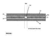
- FIG. 1 shows a cross section through a laminated glass pane with sensor window according to the prior art.
- a first disc (7) and a second disc (8) a trilayer of PVB film (5), PET film (1) and PVB film (3) is arranged.
- the PET film (1) contains a metallic coating (1b) and a stripped area (1a) by removing both the metallic coating (1b) and the PET film (1).
- the dashed line (9b) shows the region of the sensor window according to the prior art.
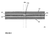
- FIG. 2 shows a cross section of a composite glass pane according to the invention with sensor window.
- a trilayer of PVB film (5) PET film (1) and PVB film (3) is arranged between a first disc (7) and a second disc (8) .
- the PET film (1) contains a metallic coating (1b) and a stripped area (1a) on the PET film (1).
- the PET film (1) is in contrast to the structure in FIG. 1 in the uncoated area (1a) not removed or removed.
- the dashed line (9a) shows the range of the sensor window according to the invention.
- FIG. 3 shows a plan view of the composite glass pane according to the invention as a windshield (12) with sensor window (9).
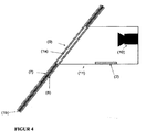
- FIG. 4 shows a cross section along the slice height I to l'in FIG. 3 the device according to the invention of the composite glass pane according to the invention as a windshield (12), sensor window (9), sensor (10) and encapsulation (11).
- a first disc (7) and a second disc (8) a not shown trilayer of PVB film (5), PET film (1) and PVB film (3) is laminated.
- the PET film (1) not shown, contains a metallic coating (1b) and a stripped region (1a) on the PET film (1), which forms the sensor window (9).
- a desiccant (2) is preferably arranged within the encapsulation (11) .
- the desiccant (2) is preferably incorporated in the surface of the encapsulation (11).
- a PVB film (3) and a metal-coated PET film (1) were combined to form a bilayer.
- two stratified areas (1a) were produced on the metal-coated PET film (1).
- the metallic coating (1b) was removed in the example according to the invention with an IR laser of the wavelength 1064 nm and a power of 20 watts, and the sensor window (9a) according to the invention was obtained.
- the sensor window (9b) of the prior art was obtained by cutting out the metallic coating (1b) and the PET film (1).
- the preparation of a trilayer from (1), (3) and (5) was carried out by connecting the bilayer from (3) and (1) with a further PVB film (5).
- the trilayer was then laminated between a first pane (7) and a second pane (8) to form a laminated glass pane.
- the lamination was carried out in an autoclave for 2.5 h at 80 ° C to 120 ° C and 8 bar to 13 bar.
- the windshield area of the windshield (12) was 1.2 m 2 , both disks (7) and (8) had a thickness of 2.1 mm.
- the PVB film (5) and the PVB film (3) had a thickness of 0.38 mm.
- the PET film (1) had a thickness of 50 microns, and was coated with silver and indium oxide (XIR ® - 75, South Europe GmbH, Grossroehrsdorf, Germany).
- the sensor window (9a) according to the invention and the sensor window (9b) according to the prior art had an area of 60 cm 2 each.
- the maximum size of the optical distortions was determined as the expansion or taper of a strip in the boundary region between the sensor windows (9a) and (9b), as well as the uncoated area of the windshields.
- the expansion / rejuvenation was measured over the black strip, which was created with a slide projector on a bright screen.
- the slide projector was placed at a distance of 4 m from a windscreen (12) placed at an angle of 27 ° to the light beam of the slide projector and produced 4 m behind the windshield (12) and 8 m away from the projector, on the bright screen, a black one Strip with a width of 12 mm.
- the maximum expansion / taper was measured, determined as the maximum increase / decrease in the width of the black stripe.
- the size of the expansion / rejuvenation can be found in the following Table 1. ⁇ b> Table 1: ⁇ / b> Comparison of the length of widening / narrowing of the 12 mm wide strip in the sensor window (9a) according to the invention and in the sensor window (9b) according to the prior art. strip width rejuvenation widening ⁇ Sensor window (9a) 12 mm 12 mm 0 mm Sensor window (9b) 7 mm 18 mm 11 mm
Landscapes
- Joining Of Glass To Other Materials (AREA)
Description
- Die Erfindung betrifft eine Verbundglasscheibe mit Sensorfenster, ein Verfahren zu deren Herstellung und deren Verwendung.
- Viele Fahrzeuge, Flugzeuge, Hubschrauber und Schiffe sind mit verschiedenen optischen Sensoren ausgestattet. Beispiele für optische Sensoren sind Kamerasysteme, wie Videokameras, Nachtsichtkameras, Restlichtverstärker oder passive Infrarotdetektoren, wie FLIR (Forward Looking Infrared). Die Kamerasysteme können Licht im ultravioletten (UV), sichtbaren (VIS) und infraroten Wellenlängenbereich (IR) nutzen. Damit lassen sich Gegenstände, Fahrzeuge, sowie Personen auch bei schlechten Witterungsverhältnissen, wie Dunkelheit und Nebel, präzise erkennen. Diese Kamerasysteme können in Kraftfahrzeugen hinter der Windschutzscheibe im Fahrgastraum platziert werden. Sie bieten damit auch im Straßenverkehr die Möglichkeit, Gefahrensituationen und Hindernisse rechtzeitig zu erkennen.
- Weitere Einsatzbereiche für optische Sensoren liegen in der elektronischen Distanzmessung (EDM), beispielsweise mit Hilfe von Laserentfernungsmessern. Hierbei kann die Entfernung zu anderen Fahrzeugen bestimmt werden. Durch Abstandsmessungen zum vorausfahrenden Fahrzeug lässt sich der notwendige Sicherheitsabstand bestimmen und die Verkehrssicherheit deutlich erhöhen. Bei automatischen Warnsystemen verringert sich die Gefahr eines Auffahrunfalls deutlich.
- Aufgrund ihrer Empfindlichkeit gegenüber Witterungseinflüssen oder Fahrtwinden müssen derartige Sensoren aber in allen Fällen durch entsprechende Scheiben geschützt werden. Viele moderne Fahrzeuge weisen heutzutage jedoch Scheiben mit speziellen metallischen Beschichtungen auf. Die metallischen Beschichtungen sind in vielen Fällen auf einer PET-Schicht aufgebracht und werden zwischen zwei PVB-Folien, sowie zwei Scheiben laminiert. Die metallischen Beschichtungen können Infrarotstrahlen abweisend sein und verringern somit die Aufheizung des Fahrgastinnenraums, sowie den Treibstoffverbrauch der Klimaanlage. Ein anderer Einsatzbereich metallischer Beschichtungen sind beheizbare Windschutzscheiben. In beheizbaren Windschutzscheiben dienen die metallischen Beschichtungen als elektrischer Heizwiderstand.
- Bei beiden Anwendungsmöglichkeiten erschwert die metallische Beschichtung in der Windschutzscheibe die Durchlässigkeit elektromagnetischer Strahlung für hinter der Windschutzscheibe angebrachte Kamera- oder Sensorsysteme. Die Windschutzscheiben müssen daher im Bereich des Sensorfensters entschichtet werden, d.h. die metallische Schicht muss in diesem Bereich entfernt werden. Trennt man aus dem Folienlaminat die betroffene PET-Schicht als Träger der metallischen Schicht heraus, kommt es beim Laminieren zu optische Störungen oder Falten an der Grenzfläche zwischen beschichtetem Folienlaminat und entschichteten Folienlaminat.
-
DE 10 2007 001 080 A1 offenbart eine elektrisch beheizbare Fensterscheibe. Diese wird mit Hilfe von elektrischen Sammelleitern mit Strom versorgt und dadurch geheizt. Die Anordnung der Leiter erfolgt dabei so, dass sich nur geringe elektromagnetische Felder entwickeln. Damit ist ein Betrieb von Geräten, die empfindlich auf elektromagnetische Felder reagieren, auch im Bereich der Scheibe möglich. -
DE 10 2006 054 938 A1 offenbart eine beheizbare Fahrzeugscheibe mit einer Ausparrung für einen Feuchtigkeitssensor. Die Fahrzeugscheibe wird mit Heizelementen beheizt, welche jeweils am Ende elektrisch verbunden sind. -
EP 1 605 729 A2 offenbart eine elektrisch beheizbare Scheibe mit einem Kamerafenster. Dieses Kamerafenster wird über eine Heizvorrichtung beschlags- und eisfrei gehalten. Das Heizelement wird an der Position des Kamerafensters in die Scheibe einlaminiert. Zusätzlich kann an der Scheibenoberfläche noch ein zusätzliches Heizelement angebracht werden. Das zusätzliche Heizelement wird bevorzugt als leitfähige Paste auf die Scheibenoberfläche gedruckt. -
US 2009/0039901 A1 offenbart ein Fenster mit einem kapazitiven Regensensor. Die Erfindung offenbart wenigstens eine Scheibe, wobei die nicht dem Wetter ausgesetzte Scheibenseite einen Detektor und Elektroden aus einem dünnen leitfähigen Material. -
WO 2007/039751 A1 offenbart eine laminierte Verbundglasscheibe. Die Verglasung beinhaltet zwei Scheiben, eine Zwischenschicht und ein elektrisch leitfähige Element, welches ebenfalls in der Zwischenschicht angeordnet ist. -
DE 37 08 577 A1 offenbart eine Automobilverglasung mit einer elektrisch leitenden und Wärmestrahlen reflektierenden Schicht. Die Schicht weist eine Transmission von weniger als 20 % und einen Flächenwiderstand von weniger als 2 Ohm pro Quadrateinheit aufweist. -
DE 102 58 522 A1 offenbart ein Verfahren zum Markieren einer Verbundglasscheibe mit einer PVB-Folie und einer darauf befindlichen Metallschicht. Nach einer Beaufschlagung mit einem Laserstrahl ändert sich die Farbe der Metallschicht. - Die Aufgabe der Erfindung liegt darin, ein Verfahren zur Herstellung einer Verbundglasscheibe mit Sensorfenster bereitzustellen, das eine einfache Herstellung eines definierten entschichteten Bereichs ermöglicht und keine optischen Auffälligkeiten im Grenzbereich zwischen beschichteten und entschichteten Folienbereich erzeugt.
- Die Aufgabe der vorliegenden Erfindung wird erfindungsgemäß durch ein Verfahren zur Herstellung einer Verbundglasscheibe mit mindestens einem Sensorfenster gemäß Anspruch 1 gelöst. Bevorzugte Ausführungen gehen aus den Unteransprüchen hervor.
- Das erfindungsgemäße Verfahren zur Herstellung einer Verbundglasscheibe umfasst in einem ersten Schritt das Verbinden einer PVB-Folie und einer metallbeschichteten PET-Folie zu einem Bilayer. In einem zweiten Schritt wird ein entschichteter Bereich auf der metallbeschichteten PET-Folie erzeugt. Dabei wird die metallische Beschichtung größtenteils, bevorzugt zu mehr als 60 Gew. % entfernt und die PET-Folie bevorzugt nur geringfügig abgetragen. Die PET-Folie weist im entschichteten Bereich bevorzugt eine Dicke von > 80 %, besonders bevorzugt mehr als 90 % der vergleichbaren Dicke der PET-Folie mit intakter metallischer Beschichtung auf. Die Herstellung eines Trilayers erfolgt durch Verbinden des Bilayers mit einer weiteren PVB-Folie. Der Trilayer wird anschließend zwischen einer ersten Scheibe und einer zweiten Scheibe zu einer Verbundglasscheibe laminiert. Die erste Scheibe und die zweite Scheibe können sowohl gleich, als auch unterschiedlich beschaffen und dimensioniert sein. Ist die Verbundglasscheibe in einem Fahrzeug, Raum oder Gebäude eingebaut, so bezieht sich bei einer im Fahrzeug eingebauten Scheibe die Bezeichnung erste Scheibe auf die außen befindliche Scheibe und die Bezeichnung zweite Scheibe auf die im Innenraum befindliche Scheibe.
- Im Bereich der entschichteten PET-Folie weist die Verbundglasscheibe ein Sensorfenster auf. Der Ausdruck Sensorfenster bezieht sich im Sinne der Erfindung auf einen für elektromagnetische Strahlung durchlässigen Bereich der erfindungsgemäßen Verbundglasscheibe. Da die PET-Folie durch die Entschichtung nur geringfügig verändert wird, treten im Grenzbereich zwischen entschichteter PET-Folie und metallbeschichteter PET-Folie kaum optische Störungen, wie Verzerrungen, Falten oder Wolkenbildung in der Folie auf. Das Sensorfenster hebt sich optisch kaum von der weiteren Verbundglasscheibe ab.
- Das Erzeugen des entschichteten Bereichs erfolgt durch Lasern, . Die Metallbeschichtung der PET-Folie wird bevorzugt durch Behandlung mit einem Laser, entfernt.
- Das Lasern erfolgt bevorzugt mit einer Wellenlänge von 300 nm bis 1300 nm und/oder einer Leistung von 1 W bis 150 W.
- Im entschichteten Bereich werden bevorzugt mindestens 80 Gew. %, bevorzugt mindestens 90 Gew. % der ursprünglichen Metallbeschichtung abgetragen.
- Die Erfindung umfasst des Weiteren eine Verbundglasscheibe mit Sensorfenster nach Anspruch 5. Die Verbundglasscheibe umfasst eine obere Scheibe, einen Trilayer aus PVB-Folie, PET-Folie und PVB-Folie, sowie eine untere Scheibe. Ist die Verbundglasscheibe in einem Fahrzeug eingebaut, so bezieht sich die Bezeichnung erste Scheibe auf die im Fahrzeug außen befindliche Scheibe und die Bezeichnung zweite Scheibe auf die im Fahrzeuginnenraum befindliche Scheibe.
- Die PET-Folie umfasst eine Metallbeschichtung und einen entschichteten Bereich. Die PET-Folie ist im entschichteten Bereich durchlässig für elektromagnetische Strahlung oder akustische Wellen und bildet in der Verbundglasscheibe ein in den Dimensionierungen des entschichteten Bereichs vorliegendes Sensorfenster. Die Scheiben enthalten bevorzugt Glas und/oder Polymere, bevorzugt Flachglas, Floatglas, Quarzglas, Borosilikatglas, Kalk-Natron-Glas, Polymethylmethacrylat und/oder Gemische davon.
- Die Metallbeschichtung weist eine Dicke von 1 nm bis 500 nm, bevorzugt von 50 nm bis 250 nm auf.
- Die Metallbeschichtung enthält bevorzugt Silber, Gold, Kupfer, Indium, Zinn, Zink und/oder Legierungen oder Mischungen davon.
- Die PET-Folie weist bevorzugt eine Dicke von 30 µm bis 120 µm auf.
- Der entschichtete Bereich weist eine Fläche von 20 cm2 bis 80 cm2 auf. Der entschichtete Bereich nimmt bevorzugt weniger als 15 %, besonders bevorzugt weniger als 5 % der Gesamtfläche der PET-Folie ein.
- Der entschichtete Bereich ist bevorzugt auf der ersten Scheibe und/oder zweiten Scheibe von opaken Bereichen umgeben.
- Der entschichtete Bereich weist bevorzugt eine mittlere Transmission für elektromagnetische Strahlung der Wellenlänge von 300 nm bis 1300 nm von > 75 %, bevorzugt > 85 % auf.
- Die Erfindung umfasst des Weiteren eine nach dem erfindungsgemäßen Verfahren hergestellte Verbundglasscheibe.
- Die Erfindung umfasst des Weiteren eine Vorrichtung mit einer erfindungsgemäßen Verbundglasscheibe, einem Sensor und einer Einkapselung. Der Sensor umfasst bevorzugt Kameras, sowie Sensoren zur Abstandsmessung. Die Einkapselung schließt den Sensor zwischen der Scheibe und dem Fahrgastinnenraum ab. Die Einkapselung ist bevorzugt im oberen Bereich der Windschutzscheibe, bevorzugt hinter einem Abdeckstreifen angebracht. Die Einkapselung enthält bevorzugt Trockenmittel, besonders bevorzugt Kieselgel, CaC12, Na2S04, Aktivkohle, Silikate, Bentonite und/oder Zeolithe. Die Trockenmittel sind bevorzugt in die Oberfläche der Einkapselung eingearbeitet.
- Die Erfindung umfasst des Weiteren die Verwendung der erfindungsgemäßen Verbundglasscheibe für Fahrzeuge, Schiffe, Flugzeuge und Hubschrauber, bevorzugt als Windschutzscheibe und/oder Heckscheibe eines Fahrzeuges.
- Im Folgenden wird die Erfindung anhand von Zeichnungen sowie eines Beispiels und Vergleichsbeispiels näher erläutert. Die Zeichnungen sind rein schematische Darstellungen und nicht maßstabsgetreu. Die Zeichnungen schränken die Erfindung in keiner Weise ein.
- Es zeigen:
-
Figur 1 einen Querschnitt einer Verbundglasscheibe mit Sensorfenster nach dem Stand der Technik, -
Figur 2 einen Querschnitt einer erfindungsgemäßen Verbundglasscheibe mit Sensorfenster, -
Figur 3 eine Draufsicht auf die erfindungsgemäße Verbundglasscheibe und -
Figur 4 einen Querschnitt der erfindungsgemäßen Vorrichtung. -
Figur 1 zeigt einen Querschnitt durch eine Verbundglasscheibe mit Sensorfenster nach dem Stand der Technik. Zwischen einer ersten Scheibe (7) und einer zweiten Scheibe (8) ist ein Trilayer aus PVB-Folie (5), PET-Folie (1) und PVB-Folie (3) angeordnet. Die PET-Folie (1) enthält eine metallische Beschichtung (1b) und einen entschichteten Bereich (1a) indem sowohl die metallische Beschichtung (1 b), als auch die PET-Folie (1) entfernt sind. Die gestrichelte Linie (9b) zeigt den Bereich des Sensorfensters nach dem Stand der Technik. -
Figur 2 zeigt einen Querschnitt einer erfindungsgemäßen Verbundglasscheibe mit Sensorfenster. Zwischen einer ersten Scheibe (7) und einer zweiten Scheibe (8) ist ein Trilayer aus PVB-Folie (5), PET-Folie (1) und PVB-Folie (3) angeordnet. Die PET-Folie (1) enthält eine metallische Beschichtung (1 b) und einen entschichteten Bereich (1a) auf der PET-Folie (1). Die PET-Folie (1) ist im Gegensatz zum Aufbau inFigur 1 im entschichteten Bereich (1a) nicht abgetragen oder entfernt. Die gestrichelte Linie (9a) zeigt den Bereich des erfindungsgemäßen Sensorfensters. -
Figur 3 zeigt eine Draufsicht auf die erfindungsgemäße Verbundglasscheibe als Windschutzscheibe (12) mit Sensorfenster (9). -
Figur 4 zeigt einen Querschnitt entlang der Scheibenhöhe I nach l'inFigur 3 der erfindungsgemäßen Vorrichtung aus der erfindungsgemäßen Verbundglasscheibe als Windschutzscheibe (12), Sensorfenster (9), Sensor (10) und Einkapselung (11). Zwischen einer ersten Scheibe (7) und einer zweiten Scheibe (8) ist ein nicht gezeigter Trilayer aus PVB-Folie (5), PET-Folie (1) und PVB-Folie (3) einlaminiert. Die nicht gezeigte PET-Folie (1) enthält eine metallische Beschichtung (1b) und einen entschichteten Bereich (1a) auf der PET-Folie (1), welcher das Sensorfenster (9) bildet. Innerhalb der Einkapselung (11) ist bevorzugt ein Trockenmittel (2) angeordnet. Das Trockenmittel (2) ist bevorzugt in die Oberfläche der Einkapselung (11) eingearbeitet. - Im Folgenden wird die Erfindung anhand eines Beispiels und eines Vergleichsbeispiels näher erläutert.
- Es wurde eine Windschutzscheibe (12) mit einem nach dem erfindungsgemäßen Verfahren hergestellten Sensorfenster (9a), gemäß
Figur 2 und mit einem Sensorfenster (9b) nach dem Stand der Technik gemäßFigur 1 hergestellt. - In einem ersten Schritt wurden eine PVB-Folie (3) und eine metallbeschichtete PET-Folie (1) zu einem Bilayer verbunden. In einem zweiten Schritt wurden zwei entschichtete Bereiche (1a) auf der metallbeschichteten PET-Folie (1) erzeugt. Die metallische Beschichtung (1b) wurde im erfindungsgemäßen Beispiel mit einem IR-Laser der Wellenlänge 1064 nm und einer Leistung von 20 Watt entfernt und das erfindungsgemäße Sensorfenster (9a) erhalten. Das Sensorfenster (9b) nach dem Stand der Technik wurde durch Ausschneiden der metallischen Beschichtung (1 b) und der PET-Folie (1) erhalten. Die Herstellung eines Trilayers aus (1), (3) und (5) erfolgte durch Verbinden des Bilayers aus (3) und (1) mit einer weiteren PVB-Folie (5). Der Trilayer wurde anschließend zwischen einer ersten Scheibe (7) und einer zweiten Scheibe (8) zu einer Verbundglasscheibe laminiert. Das Laminieren erfolgte im Autoklaven für 2,5 h bei 80°C bis 120 °C und 8 bar bis 13 bar.
- Die Windschutzscheibenfläche der Windschutzscheibe (12) betrug 1,2 m2, beide Scheiben (7) und (8) wiesen eine Dicke von 2,1 mm auf. Die PVB-Folie (5) und die PVB-Folie (3) wiesen eine Dicke von 0,38 mm auf. Die PET-Folie (1) wies eine Dicke von 50 µm auf und war mit Silber und Indiumoxid beschichtet (XIR® - 75, Southwall Europe GmbH, Großröhrsdorf, Deutschland). Das erfindungsgemäße Sensorfenster (9a) und das Sensorfenster (9b) nach dem Stand der Technik wiesen eine Fläche von jeweils 60 cm2 auf.
- Es wurde die maximale Größe der optischen Verzerrungen als Aufweitung oder Verjüngung eines Streifens im Grenzbereich zwischen den Sensorfenstern (9a) und (9b), sowie dem nicht entschichteten Bereich der Windschutzscheiben bestimmt. Die Aufweitung / Verjüngung wurde über dem schwarzen Streifen gemessen, welcher mit einem Diaprojektor auf einer hellen Leinwand erzeugt wurden. Der Diaprojektor war in einem Abstand von 4 m zu einer im Winkel von 27° zum Lichtstrahl des Diaprojektors aufgestellten Windschutzscheibe (12) angeordnet und erzeugte 4 m hinter der Windschutzscheibe (12) und 8 m vom Projektor entfernt, auf der hellen Leinwand, einen schwarzen Streifen mit einer Breite von 12 mm. Im Grenzbereich der Sensorfenster (9a) und (9b), sowie im Fensterbereich selbst, wurde die maximale Aufweitung / Verjüngung gemessen, bestimmt als maximale Zunahme / Abnahme der Breite des schwarzen Streifens. Die Größe der Aufweitung / Verjüngung findet sich in der folgenden Tabelle 1.
Tabelle 1: Vergleich der Länge der Aufweitung / Verjüngung des 12 mm breiten Streifens im erfindungsgemäßen Sensorfenster (9a) und im Sensorfenster (9b) nach dem Stand der Technik. Streifenbreite Verjüngung Verbreiterung Δ Sensorfenster (9a) 12 mm 12 mm 0 mm Sensorfenster (9b) 7 mm 18 mm 11 mm - Aus Tabelle 1 ist ersichtlich, dass der Betrag Δ der Aufweitung/Verjüngung im Grenzbereich zum erfindungsgemäßen Sensorfenster (9a) nicht messbar und damit deutlich geringer ist, als im Sensorfenster (9b) mit Δ = 11 mm nach dem Stand der Technik. Der Betrag Δ errechnet sich aus der Summe der Abnahme der Verjüngung und der Zunahme der Verbreiterung. Diese Ergebnisse waren überraschend und nicht naheliegend.
-
- (1)
- metallbeschichtete PET-Folie,
- (1a)
- entschichteter Bereich,
- (1b)
- metallische Beschichtung,
- (2)
- Trockenmittel,
- (3)
- PVB-Folie,
- (4)
- Bilayer,
- (5)
- PVB-Folie,
- (6)
- Trilayer,
- (7)
- erste Scheibe,
- (8)
- zweite Scheibe,
- (9)
- Sensorfenster,
- (9a)
- erfindungsgemäßes Sensorfenster,
- (9b)
- Sensorfenster nach dem Stand der Technik,
- (10)
- Sensor,
- (11)
- Einkapselung,
- (12)
- Windschutzscheibe und
- (1,1')
- Schnitt entlang der Windschutzscheibe.
Claims (12)
- Verfahren zur Herstellung einer Verbundglasscheibe mit mindestens einem Sensorfenster, wobeia. eine metallbeschichtete PET-Folie (1) über deren von der Metallbeschichtung (1b) abgewandten Seite mit einer PVB-Folie (3) zu einem Bilayer (4) verbunden werden,b. ein entschichteter Bereich (1a) durch Lasern auf der metallbeschichteten PET-Folie (1), der eine Fläche 20 cm2 bis 80 cm2 aufweist, erzeugt wird,c. ein Trilayer (6) durch Verbinden des Bilayers (4) auf der PET-Seite mit einer PVB-Folie (5) erzeugt wird undd. der Trilayer (6) zwischen einer ersten Scheibe (7) und einer zweiten Scheibe (8) laminiert wird und ein Sensorfenster (9) entsprechend dem entschichteten Bereich (1a) erhalten wird.
- Verfahren nach Anspruch 1, wobei das Lasern mit einer Wellenlänge von 300 nm bis 1300 nm erfolgt.
- Verfahren nach einem der Ansprüche 1 oder 2, wobei das Lasern mit einer Leistung von 1 W bis 150 W erfolgt.
- Verfahren nach einem der Ansprüche 1 bis 3, wobei im entschichteten Bereich (1a) mindestens 80 Gew. %, bevorzugt mindestens 90 Gew. % der ursprünglichen Metallbeschichtung abgetragen werden.
- Verbundglasscheibe umfassend:a. eine erste Scheibe (7),b. eine PVB-Folie (5) auf der ersten Scheibe (7),c. eine PET-Folie (1), umfassend eine Metallbeschichtung (1b) und einen entschichteten Bereich (1a) der eine Fläche von 20 cm2 bis 80 cm2 aufweist, auf der PVB-Folie (5), wobei im entschichteten Bereich (1a) mindestens 90 Gew. % der ursprünglichen Metallbeschichtung durch Lasern abgetragen sind,d. eine PVB-Folie (3) auf der PET-Folie (1),e. eine zweiten Scheibe (8) auf der PVB-Folie (3) undf. ein Sensorfenster (9) entsprechend dem entschichteten Bereich (1a).
- Verbundglasscheibe nach Anspruch 5, wobei die Metallbeschichtung (1b) eine Dicke von 1 nm bis 500 nm, bevorzugt von 50 nm bis 250 nm aufweist.
- Verbundglasscheibe nach einem der Ansprüche 5 bis 6, wobei die Metallbeschichtung (1b) Silber, Gold, Kupfer, Indium, Zinn, Zink und/oder Legierungen oder Mischungen davon enthält.
- Verbundglasscheibe nach einem der Ansprüche 5 bis 7, wobei die PET-Folie (1) eine Dicke von 20 µm bis 120 µm aufweist.
- Verbundglasscheibe nach einem der Ansprüche 5 bis 8, wobei der entschichtete Bereich (1a) auf der ersten Scheibe (7) und/oder zweiten Scheibe (8) von opaken Bereichen (9) umgeben ist.
- Verbundglasscheibe nach einem der Ansprüche 5 bis 9, wobei der entschichtete Bereich (1a) eine mittlere Transmission für elektromagnetische Strahlung der Wellenlänge von 300 nm bis 1300 nm von > 75 %, bevorzugt > 85 % aufweist.
- Vorrichtung umfassend eine Verbundglasscheibe nach den Ansprüchen 5 bis 10, einen Sensor (10) in der Position des Sensorfensters (9) und eine Einkapselung (11) für den Sensor.
- Verwendung der Verbundglasscheibe und/oder Vorrichtung nach einem der Ansprüche 6 bis 11 für Fahrzeuge, Schiffe, Flugzeuge und Hubschrauber, bevorzugt als Windschutzscheibe und/oder Heckscheibe eines Fahrzeuges.
Priority Applications (2)
| Application Number | Priority Date | Filing Date | Title |
|---|---|---|---|
| PL09176180T PL2325002T5 (pl) | 2009-11-17 | 2009-11-17 | Sposób wytwarzania szyby zespolonej z oknem dla czujnika |
| EP20090176180 EP2325002B2 (de) | 2009-11-17 | 2009-11-17 | Verfahren zur Herstellung einer Verbundglasscheibe mit Sensorfenster |
Applications Claiming Priority (1)
| Application Number | Priority Date | Filing Date | Title |
|---|---|---|---|
| EP20090176180 EP2325002B2 (de) | 2009-11-17 | 2009-11-17 | Verfahren zur Herstellung einer Verbundglasscheibe mit Sensorfenster |
Publications (3)
| Publication Number | Publication Date |
|---|---|
| EP2325002A1 EP2325002A1 (de) | 2011-05-25 |
| EP2325002B1 EP2325002B1 (de) | 2012-08-29 |
| EP2325002B2 true EP2325002B2 (de) | 2015-04-15 |
Family
ID=42062255
Family Applications (1)
| Application Number | Title | Priority Date | Filing Date |
|---|---|---|---|
| EP20090176180 Not-in-force EP2325002B2 (de) | 2009-11-17 | 2009-11-17 | Verfahren zur Herstellung einer Verbundglasscheibe mit Sensorfenster |
Country Status (2)
| Country | Link |
|---|---|
| EP (1) | EP2325002B2 (de) |
| PL (1) | PL2325002T5 (de) |
Families Citing this family (11)
| Publication number | Priority date | Publication date | Assignee | Title |
|---|---|---|---|---|
| EP2334141A1 (de) | 2009-12-11 | 2011-06-15 | Saint-Gobain Glass France | Beschichtete Scheibe mit beheizbarem Kommunikationsfenster |
| BR112014017114B1 (pt) * | 2012-03-05 | 2018-10-16 | Saint Gobain | processo para produzir um painel de vidro laminado e dispositivo para tratar a laser um filme de polímero revestido |
| DE102012012566B3 (de) * | 2012-06-23 | 2013-12-05 | Audi Ag | Verbundscheibe für einen Kraftwagen und Kraftwagen mit einer solchen Verbundscheibe. |
| CA2998306C (en) * | 2015-10-23 | 2020-05-05 | Saint-Gobain Glass France | Method for producing a composite pane having an infrared-reflecting coating on a carrier film |
| DE102017101321A1 (de) | 2017-01-24 | 2018-07-26 | geronimo GmbH | Abstandswarnsystem für das nachfolgende Fahrzeug |
| EP3616905A4 (de) * | 2017-03-27 | 2021-04-28 | Kuraray Co., Ltd. | Polyvinylacetalharzfolie für verbundglas |
| JP7228047B2 (ja) * | 2019-01-15 | 2023-02-22 | サン-ゴバン グラス フランス | 統合されているセンサーモジュールを有している乗物ウインドウ |
| DE102019112454A1 (de) * | 2019-05-13 | 2020-11-19 | Volkswagen Aktiengesellschaft | Glasscheibe für ein Fahrzeug, Scheiben-Sensor-Einheit und Fahrzeug |
| JP2021147243A (ja) * | 2020-03-13 | 2021-09-27 | 日本板硝子株式会社 | 自動車用窓ガラス |
| EP3960441A1 (de) * | 2020-08-25 | 2022-03-02 | Schott Ag | Fahrzeugscheibe mit erhöhter belastbarkeit gegenüber umwelteinflüssen |
| WO2023068035A1 (ja) * | 2021-10-20 | 2023-04-27 | セントラル硝子株式会社 | 窓ガラス |
Citations (8)
| Publication number | Priority date | Publication date | Assignee | Title |
|---|---|---|---|---|
| US5131967A (en) † | 1990-12-21 | 1992-07-21 | Ford Motor Company | Method of making laminated glazing units |
| WO2000072635A1 (en) † | 1999-05-20 | 2000-11-30 | Glaverbel | Automotive glazing panel having an electrically heatable solar control coating layer |
| WO2001068395A1 (en) † | 2000-03-14 | 2001-09-20 | Glaverbel | Automotive glazing panel having an electrically heatable solar control coating layer provided with data transmission windows |
| US6356236B1 (en) † | 1998-04-21 | 2002-03-12 | Saint-Gobain Glass France | Transparent plate, in particular partition glass provided with a coating reflecting radiation and a window permeable to high frequency radiation |
| US20020094407A1 (en) † | 1997-04-24 | 2002-07-18 | Saint-Gobain Glass France | Method for making a laminated glass sheet |
| WO2004032569A2 (en) † | 2002-10-03 | 2004-04-15 | Ppg Industries Ohio, Inc. | Heatable article having a configured heating member |
| US20060202897A1 (en) † | 2002-10-22 | 2006-09-14 | Philippe Roquiny | Glazing panel with a radiation-reflective coating layer |
| WO2009086869A1 (en) † | 2008-01-04 | 2009-07-16 | Saint-Gobain Glass France | Glass pane and glass pane arrangement |
Family Cites Families (7)
| Publication number | Priority date | Publication date | Assignee | Title |
|---|---|---|---|---|
| DE3708577A1 (de) * | 1987-03-17 | 1988-09-29 | Ver Glaswerke Gmbh | Mit einer elektrisch leitenden und waermestrahlen reflektierenden schicht versehene autoglasscheibe |
| DE10258522B4 (de) * | 2002-12-14 | 2014-11-13 | Volkswagen Ag | Verfahren zum Markieren einer Verbundglasscheibe und Verbundglasscheibe mit Markierung |
| GB0408392D0 (en) | 2004-04-15 | 2004-05-19 | Pilkington Plc | Electrically heated window |
| BE1016680A3 (fr) * | 2005-07-13 | 2007-04-03 | Glaverbel | Vitrage comportant un detecteur de pluie capacitif. |
| GB0520303D0 (en) * | 2005-10-06 | 2005-11-16 | Pilkington Plc | Laminated glazing |
| DE102006054938A1 (de) | 2006-11-22 | 2008-05-29 | Hella Kgaa Hueck & Co. | Fensterscheibe für Kraftfahrzeuge |
| DE102007001080A1 (de) | 2007-01-04 | 2008-07-10 | Saint-Gobain Sekurit Deutschland Gmbh & Co. Kg | Elektrisch beheizbare Fensterscheibe |
-
2009
- 2009-11-17 EP EP20090176180 patent/EP2325002B2/de not_active Not-in-force
- 2009-11-17 PL PL09176180T patent/PL2325002T5/pl unknown
Patent Citations (8)
| Publication number | Priority date | Publication date | Assignee | Title |
|---|---|---|---|---|
| US5131967A (en) † | 1990-12-21 | 1992-07-21 | Ford Motor Company | Method of making laminated glazing units |
| US20020094407A1 (en) † | 1997-04-24 | 2002-07-18 | Saint-Gobain Glass France | Method for making a laminated glass sheet |
| US6356236B1 (en) † | 1998-04-21 | 2002-03-12 | Saint-Gobain Glass France | Transparent plate, in particular partition glass provided with a coating reflecting radiation and a window permeable to high frequency radiation |
| WO2000072635A1 (en) † | 1999-05-20 | 2000-11-30 | Glaverbel | Automotive glazing panel having an electrically heatable solar control coating layer |
| WO2001068395A1 (en) † | 2000-03-14 | 2001-09-20 | Glaverbel | Automotive glazing panel having an electrically heatable solar control coating layer provided with data transmission windows |
| WO2004032569A2 (en) † | 2002-10-03 | 2004-04-15 | Ppg Industries Ohio, Inc. | Heatable article having a configured heating member |
| US20060202897A1 (en) † | 2002-10-22 | 2006-09-14 | Philippe Roquiny | Glazing panel with a radiation-reflective coating layer |
| WO2009086869A1 (en) † | 2008-01-04 | 2009-07-16 | Saint-Gobain Glass France | Glass pane and glass pane arrangement |
Also Published As
| Publication number | Publication date |
|---|---|
| PL2325002T5 (pl) | 2016-06-30 |
| PL2325002T3 (pl) | 2013-01-31 |
| EP2325002B1 (de) | 2012-08-29 |
| EP2325002A1 (de) | 2011-05-25 |
Similar Documents
| Publication | Publication Date | Title |
|---|---|---|
| EP2325002B2 (de) | Verfahren zur Herstellung einer Verbundglasscheibe mit Sensorfenster | |
| EP2462007B1 (de) | Scheibe mit optisch transparentem sensorfeld | |
| EP2823689B1 (de) | Scheibenanordnung mit elektrisch beheizbarer streulichtblende | |
| EP3028534B1 (de) | Beheizbare laminierte seitenscheibe | |
| EP2591638B1 (de) | Verbundscheibe mit einer elektrisch beheizbaren beschichtung | |
| EP3362284B1 (de) | Beheizbare laminierte fahrzeugscheibe mit verbesserter wärmeverteilung | |
| EP2718098B1 (de) | Heizbare verbundscheibe mit sicherheitsfunktion | |
| EP2446701A1 (de) | Scheibe mit beheizbaren, optisch transparenten sensorfeld | |
| WO2010136400A1 (de) | ELEKTRISCH GROßFLÄCHIG BEHEIZBARER, TRANSPARENTER GEGENSTAND, VERFAHREN ZU SEINER HERSTELLUNG UND SEINE VERWENDUNG | |
| WO2022167333A1 (de) | Verbundscheibe mit elektrisch beheizbarem kamerafenster | |
| WO2021104887A1 (de) | Verbundscheibe mit in thermoplastischer zwischenschicht eingelagertem funktionselement und entlüftungsstruktur | |
| DE202009018502U1 (de) | Scheibe mit beheizbaren, optisch transparenten Sensorfeld | |
| WO2022218838A1 (de) | Scheibenanordnung mit beheizbarem sensorfenster | |
| DE202022002755U1 (de) | Scheibe mit beheizbaren Sensorfeld | |
| EP4288283A1 (de) | Verbundscheibe mit elektrisch beheizbarem kamerafenster | |
| WO2023046477A1 (de) | Verglasung mit segmentiertem pdlc-funktionselement und elektrisch steuerbaren optischen eigenschaften | |
| EP4103922A1 (de) | Fahrzeugscheibe mit integriertem temperatursensor | |
| DE102009004045A1 (de) | Scheibe mit beheizbarem optisch transparentem Scheibensegment | |
| EP4353050A1 (de) | Scheibe mit muster-förmiger funktionsbeschichtung | |
| EP2206601A1 (de) | Scheibe mit einem Funktionselement | |
| DE202021102128U1 (de) | Verbundscheibe mit beheizbarem Sensorfenster | |
| EP4532196B1 (de) | Beheizbare verbundscheibe mit akustisch dämpfenden eigenschaften | |
| EP2256856A1 (de) | Transparente, flächenförmige Vorrichtung zum Empfangen und/oder Senden elektromagnetischer Strahlung mit mindestens einer weiteren Funktion, Verfahren zu ihrer Herstellung und ihre Verwendung | |
| EP4326549A1 (de) | Verfahren zur steuerung einer verglasungseinheit mit elektrisch steuerbaren optischen eigenschaften | |
| WO2024068174A1 (de) | Anordnung für fahrerassistenzsystem mit einer beheizbaren fahrzeugverglasung |
Legal Events
| Date | Code | Title | Description |
|---|---|---|---|
| PUAI | Public reference made under article 153(3) epc to a published international application that has entered the european phase |
Free format text: ORIGINAL CODE: 0009012 |
|
| AK | Designated contracting states |
Kind code of ref document: A1 Designated state(s): AT BE BG CH CY CZ DE DK EE ES FI FR GB GR HR HU IE IS IT LI LT LU LV MC MK MT NL NO PL PT RO SE SI SK SM TR |
|
| 17P | Request for examination filed |
Effective date: 20111110 |
|
| 17Q | First examination report despatched |
Effective date: 20120102 |
|
| GRAP | Despatch of communication of intention to grant a patent |
Free format text: ORIGINAL CODE: EPIDOSNIGR1 |
|
| GRAS | Grant fee paid |
Free format text: ORIGINAL CODE: EPIDOSNIGR3 |
|
| GRAA | (expected) grant |
Free format text: ORIGINAL CODE: 0009210 |
|
| AK | Designated contracting states |
Kind code of ref document: B1 Designated state(s): AT BE BG CH CY CZ DE DK EE ES FI FR GB GR HR HU IE IS IT LI LT LU LV MC MK MT NL NO PL PT RO SE SI SK SM TR |
|
| REG | Reference to a national code |
Ref country code: GB Ref legal event code: FG4D Free format text: NOT ENGLISH |
|
| REG | Reference to a national code |
Ref country code: CH Ref legal event code: EP |
|
| REG | Reference to a national code |
Ref country code: AT Ref legal event code: REF Ref document number: 572836 Country of ref document: AT Kind code of ref document: T Effective date: 20120915 |
|
| REG | Reference to a national code |
Ref country code: IE Ref legal event code: FG4D Free format text: LANGUAGE OF EP DOCUMENT: GERMAN |
|
| REG | Reference to a national code |
Ref country code: DE Ref legal event code: R096 Ref document number: 502009004525 Country of ref document: DE Effective date: 20121025 |
|
| REG | Reference to a national code |
Ref country code: NL Ref legal event code: VDEP Effective date: 20120829 |
|
| REG | Reference to a national code |
Ref country code: LT Ref legal event code: MG4D Effective date: 20120829 |
|
| PG25 | Lapsed in a contracting state [announced via postgrant information from national office to epo] |
Ref country code: NO Free format text: LAPSE BECAUSE OF FAILURE TO SUBMIT A TRANSLATION OF THE DESCRIPTION OR TO PAY THE FEE WITHIN THE PRESCRIBED TIME-LIMIT Effective date: 20121129 Ref country code: HR Free format text: LAPSE BECAUSE OF FAILURE TO SUBMIT A TRANSLATION OF THE DESCRIPTION OR TO PAY THE FEE WITHIN THE PRESCRIBED TIME-LIMIT Effective date: 20120829 Ref country code: LT Free format text: LAPSE BECAUSE OF FAILURE TO SUBMIT A TRANSLATION OF THE DESCRIPTION OR TO PAY THE FEE WITHIN THE PRESCRIBED TIME-LIMIT Effective date: 20120829 Ref country code: IS Free format text: LAPSE BECAUSE OF FAILURE TO SUBMIT A TRANSLATION OF THE DESCRIPTION OR TO PAY THE FEE WITHIN THE PRESCRIBED TIME-LIMIT Effective date: 20121229 Ref country code: FI Free format text: LAPSE BECAUSE OF FAILURE TO SUBMIT A TRANSLATION OF THE DESCRIPTION OR TO PAY THE FEE WITHIN THE PRESCRIBED TIME-LIMIT Effective date: 20120829 |
|
| REG | Reference to a national code |
Ref country code: PL Ref legal event code: T3 |
|
| REG | Reference to a national code |
Ref country code: SK Ref legal event code: T3 Ref document number: E 12835 Country of ref document: SK |
|
| PG25 | Lapsed in a contracting state [announced via postgrant information from national office to epo] |
Ref country code: SI Free format text: LAPSE BECAUSE OF FAILURE TO SUBMIT A TRANSLATION OF THE DESCRIPTION OR TO PAY THE FEE WITHIN THE PRESCRIBED TIME-LIMIT Effective date: 20120829 Ref country code: PT Free format text: LAPSE BECAUSE OF FAILURE TO SUBMIT A TRANSLATION OF THE DESCRIPTION OR TO PAY THE FEE WITHIN THE PRESCRIBED TIME-LIMIT Effective date: 20121231 Ref country code: GR Free format text: LAPSE BECAUSE OF FAILURE TO SUBMIT A TRANSLATION OF THE DESCRIPTION OR TO PAY THE FEE WITHIN THE PRESCRIBED TIME-LIMIT Effective date: 20121130 Ref country code: SE Free format text: LAPSE BECAUSE OF FAILURE TO SUBMIT A TRANSLATION OF THE DESCRIPTION OR TO PAY THE FEE WITHIN THE PRESCRIBED TIME-LIMIT Effective date: 20120829 Ref country code: LV Free format text: LAPSE BECAUSE OF FAILURE TO SUBMIT A TRANSLATION OF THE DESCRIPTION OR TO PAY THE FEE WITHIN THE PRESCRIBED TIME-LIMIT Effective date: 20120829 |
|
| PG25 | Lapsed in a contracting state [announced via postgrant information from national office to epo] |
Ref country code: ES Free format text: LAPSE BECAUSE OF FAILURE TO SUBMIT A TRANSLATION OF THE DESCRIPTION OR TO PAY THE FEE WITHIN THE PRESCRIBED TIME-LIMIT Effective date: 20121210 Ref country code: DK Free format text: LAPSE BECAUSE OF FAILURE TO SUBMIT A TRANSLATION OF THE DESCRIPTION OR TO PAY THE FEE WITHIN THE PRESCRIBED TIME-LIMIT Effective date: 20120829 Ref country code: RO Free format text: LAPSE BECAUSE OF FAILURE TO SUBMIT A TRANSLATION OF THE DESCRIPTION OR TO PAY THE FEE WITHIN THE PRESCRIBED TIME-LIMIT Effective date: 20120829 Ref country code: EE Free format text: LAPSE BECAUSE OF FAILURE TO SUBMIT A TRANSLATION OF THE DESCRIPTION OR TO PAY THE FEE WITHIN THE PRESCRIBED TIME-LIMIT Effective date: 20120829 Ref country code: NL Free format text: LAPSE BECAUSE OF FAILURE TO SUBMIT A TRANSLATION OF THE DESCRIPTION OR TO PAY THE FEE WITHIN THE PRESCRIBED TIME-LIMIT Effective date: 20120829 |
|
| BERE | Be: lapsed |
Owner name: SAINT-GOBAIN GLASS FRANCE Effective date: 20121130 |
|
| PG25 | Lapsed in a contracting state [announced via postgrant information from national office to epo] |
Ref country code: IT Free format text: LAPSE BECAUSE OF FAILURE TO SUBMIT A TRANSLATION OF THE DESCRIPTION OR TO PAY THE FEE WITHIN THE PRESCRIBED TIME-LIMIT Effective date: 20120829 |
|
| PLBI | Opposition filed |
Free format text: ORIGINAL CODE: 0009260 |
|
| PLAX | Notice of opposition and request to file observation + time limit sent |
Free format text: ORIGINAL CODE: EPIDOSNOBS2 |
|
| 26 | Opposition filed |
Opponent name: PILKINGTON GROUP LIMITED Effective date: 20130529 |
|
| PG25 | Lapsed in a contracting state [announced via postgrant information from national office to epo] |
Ref country code: BG Free format text: LAPSE BECAUSE OF FAILURE TO SUBMIT A TRANSLATION OF THE DESCRIPTION OR TO PAY THE FEE WITHIN THE PRESCRIBED TIME-LIMIT Effective date: 20121129 |
|
| REG | Reference to a national code |
Ref country code: IE Ref legal event code: MM4A |
|
| REG | Reference to a national code |
Ref country code: DE Ref legal event code: R026 Ref document number: 502009004525 Country of ref document: DE Effective date: 20130529 |
|
| PG25 | Lapsed in a contracting state [announced via postgrant information from national office to epo] |
Ref country code: BE Free format text: LAPSE BECAUSE OF NON-PAYMENT OF DUE FEES Effective date: 20121130 |
|
| PLBB | Reply of patent proprietor to notice(s) of opposition received |
Free format text: ORIGINAL CODE: EPIDOSNOBS3 |
|
| PG25 | Lapsed in a contracting state [announced via postgrant information from national office to epo] |
Ref country code: IE Free format text: LAPSE BECAUSE OF NON-PAYMENT OF DUE FEES Effective date: 20121117 |
|
| PG25 | Lapsed in a contracting state [announced via postgrant information from national office to epo] |
Ref country code: CY Free format text: LAPSE BECAUSE OF FAILURE TO SUBMIT A TRANSLATION OF THE DESCRIPTION OR TO PAY THE FEE WITHIN THE PRESCRIBED TIME-LIMIT Effective date: 20120829 Ref country code: MT Free format text: LAPSE BECAUSE OF FAILURE TO SUBMIT A TRANSLATION OF THE DESCRIPTION OR TO PAY THE FEE WITHIN THE PRESCRIBED TIME-LIMIT Effective date: 20120829 |
|
| PG25 | Lapsed in a contracting state [announced via postgrant information from national office to epo] |
Ref country code: TR Free format text: LAPSE BECAUSE OF FAILURE TO SUBMIT A TRANSLATION OF THE DESCRIPTION OR TO PAY THE FEE WITHIN THE PRESCRIBED TIME-LIMIT Effective date: 20120829 Ref country code: MC Free format text: LAPSE BECAUSE OF NON-PAYMENT OF DUE FEES Effective date: 20121130 |
|
| PG25 | Lapsed in a contracting state [announced via postgrant information from national office to epo] |
Ref country code: LU Free format text: LAPSE BECAUSE OF NON-PAYMENT OF DUE FEES Effective date: 20121117 Ref country code: SM Free format text: LAPSE BECAUSE OF FAILURE TO SUBMIT A TRANSLATION OF THE DESCRIPTION OR TO PAY THE FEE WITHIN THE PRESCRIBED TIME-LIMIT Effective date: 20120829 |
|
| REG | Reference to a national code |
Ref country code: CH Ref legal event code: PL |
|
| PG25 | Lapsed in a contracting state [announced via postgrant information from national office to epo] |
Ref country code: LI Free format text: LAPSE BECAUSE OF NON-PAYMENT OF DUE FEES Effective date: 20131130 Ref country code: HU Free format text: LAPSE BECAUSE OF FAILURE TO SUBMIT A TRANSLATION OF THE DESCRIPTION OR TO PAY THE FEE WITHIN THE PRESCRIBED TIME-LIMIT Effective date: 20091117 Ref country code: CH Free format text: LAPSE BECAUSE OF NON-PAYMENT OF DUE FEES Effective date: 20131130 |
|
| PUAH | Patent maintained in amended form |
Free format text: ORIGINAL CODE: 0009272 |
|
| STAA | Information on the status of an ep patent application or granted ep patent |
Free format text: STATUS: PATENT MAINTAINED AS AMENDED |
|
| 27A | Patent maintained in amended form |
Effective date: 20150415 |
|
| AK | Designated contracting states |
Kind code of ref document: B2 Designated state(s): AT BE BG CH CY CZ DE DK EE ES FI FR GB GR HR HU IE IS IT LI LT LU LV MC MK MT NL NO PL PT RO SE SI SK SM TR |
|
| REG | Reference to a national code |
Ref country code: DE Ref legal event code: R102 Ref document number: 502009004525 Country of ref document: DE |
|
| REG | Reference to a national code |
Ref country code: DE Ref legal event code: R102 Ref document number: 502009004525 Country of ref document: DE Effective date: 20150415 |
|
| PG25 | Lapsed in a contracting state [announced via postgrant information from national office to epo] |
Ref country code: MK Free format text: LAPSE BECAUSE OF FAILURE TO SUBMIT A TRANSLATION OF THE DESCRIPTION OR TO PAY THE FEE WITHIN THE PRESCRIBED TIME-LIMIT Effective date: 20120829 |
|
| REG | Reference to a national code |
Ref country code: SK Ref legal event code: T5 Ref document number: E 12835 Country of ref document: SK |
|
| REG | Reference to a national code |
Ref country code: FR Ref legal event code: PLFP Year of fee payment: 7 |
|
| REG | Reference to a national code |
Ref country code: AT Ref legal event code: MM01 Ref document number: 572836 Country of ref document: AT Kind code of ref document: T Effective date: 20141117 |
|
| PG25 | Lapsed in a contracting state [announced via postgrant information from national office to epo] |
Ref country code: AT Free format text: LAPSE BECAUSE OF NON-PAYMENT OF DUE FEES Effective date: 20141117 |
|
| REG | Reference to a national code |
Ref country code: FR Ref legal event code: PLFP Year of fee payment: 8 |
|
| REG | Reference to a national code |
Ref country code: FR Ref legal event code: PLFP Year of fee payment: 9 |
|
| REG | Reference to a national code |
Ref country code: FR Ref legal event code: PLFP Year of fee payment: 10 |
|
| PGFP | Annual fee paid to national office [announced via postgrant information from national office to epo] |
Ref country code: DE Payment date: 20201103 Year of fee payment: 12 Ref country code: FR Payment date: 20201013 Year of fee payment: 12 Ref country code: CZ Payment date: 20201030 Year of fee payment: 12 Ref country code: GB Payment date: 20201104 Year of fee payment: 12 |
|
| PGFP | Annual fee paid to national office [announced via postgrant information from national office to epo] |
Ref country code: SK Payment date: 20201015 Year of fee payment: 12 Ref country code: PL Payment date: 20201013 Year of fee payment: 12 |
|
| REG | Reference to a national code |
Ref country code: DE Ref legal event code: R119 Ref document number: 502009004525 Country of ref document: DE |
|
| REG | Reference to a national code |
Ref country code: SK Ref legal event code: MM4A Ref document number: E 12835 Country of ref document: SK Effective date: 20211117 |
|
| GBPC | Gb: european patent ceased through non-payment of renewal fee |
Effective date: 20211117 |
|
| PG25 | Lapsed in a contracting state [announced via postgrant information from national office to epo] |
Ref country code: SK Free format text: LAPSE BECAUSE OF NON-PAYMENT OF DUE FEES Effective date: 20211117 Ref country code: CZ Free format text: LAPSE BECAUSE OF NON-PAYMENT OF DUE FEES Effective date: 20211117 |
|
| PG25 | Lapsed in a contracting state [announced via postgrant information from national office to epo] |
Ref country code: GB Free format text: LAPSE BECAUSE OF NON-PAYMENT OF DUE FEES Effective date: 20211117 Ref country code: DE Free format text: LAPSE BECAUSE OF NON-PAYMENT OF DUE FEES Effective date: 20220601 |
|
| PG25 | Lapsed in a contracting state [announced via postgrant information from national office to epo] |
Ref country code: FR Free format text: LAPSE BECAUSE OF NON-PAYMENT OF DUE FEES Effective date: 20211130 |
|
| PG25 | Lapsed in a contracting state [announced via postgrant information from national office to epo] |
Ref country code: PL Free format text: LAPSE BECAUSE OF NON-PAYMENT OF DUE FEES Effective date: 20211117 |