EP2813731A1 - Dispositif de restriction rotationnelle pour appareil rotatif - Google Patents
Dispositif de restriction rotationnelle pour appareil rotatif Download PDFInfo
- Publication number
- EP2813731A1 EP2813731A1 EP13746993.8A EP13746993A EP2813731A1 EP 2813731 A1 EP2813731 A1 EP 2813731A1 EP 13746993 A EP13746993 A EP 13746993A EP 2813731 A1 EP2813731 A1 EP 2813731A1
- Authority
- EP
- European Patent Office
- Prior art keywords
- rotation
- dog
- rotary
- rotation shaft
- rotary cam
- Prior art date
- Legal status (The legal status is an assumption and is not a legal conclusion. Google has not performed a legal analysis and makes no representation as to the accuracy of the status listed.)
- Granted
Links
- 239000000523 sample Substances 0.000 description 5
- 230000002093 peripheral effect Effects 0.000 description 4
- 238000001514 detection method Methods 0.000 description 3
- 238000005259 measurement Methods 0.000 description 2
- 238000006073 displacement reaction Methods 0.000 description 1
- 238000000034 method Methods 0.000 description 1
Images


Classifications
-
- F—MECHANICAL ENGINEERING; LIGHTING; HEATING; WEAPONS; BLASTING
- F16—ENGINEERING ELEMENTS AND UNITS; GENERAL MEASURES FOR PRODUCING AND MAINTAINING EFFECTIVE FUNCTIONING OF MACHINES OR INSTALLATIONS; THERMAL INSULATION IN GENERAL
- F16D—COUPLINGS FOR TRANSMITTING ROTATION; CLUTCHES; BRAKES
- F16D3/00—Yielding couplings, i.e. with means permitting movement between the connected parts during the drive
- F16D3/02—Yielding couplings, i.e. with means permitting movement between the connected parts during the drive adapted to specific functions
- F16D3/04—Yielding couplings, i.e. with means permitting movement between the connected parts during the drive adapted to specific functions specially adapted to allow radial displacement, e.g. Oldham couplings
-
- F—MECHANICAL ENGINEERING; LIGHTING; HEATING; WEAPONS; BLASTING
- F16—ENGINEERING ELEMENTS AND UNITS; GENERAL MEASURES FOR PRODUCING AND MAINTAINING EFFECTIVE FUNCTIONING OF MACHINES OR INSTALLATIONS; THERMAL INSULATION IN GENERAL
- F16M—FRAMES, CASINGS OR BEDS OF ENGINES, MACHINES OR APPARATUS, NOT SPECIFIC TO ENGINES, MACHINES OR APPARATUS PROVIDED FOR ELSEWHERE; STANDS; SUPPORTS
- F16M11/00—Stands or trestles as supports for apparatus or articles placed thereon Stands for scientific apparatus such as gravitational force meters
- F16M11/02—Heads
- F16M11/04—Means for attachment of apparatus; Means allowing adjustment of the apparatus relatively to the stand
- F16M11/06—Means for attachment of apparatus; Means allowing adjustment of the apparatus relatively to the stand allowing pivoting
-
- F—MECHANICAL ENGINEERING; LIGHTING; HEATING; WEAPONS; BLASTING
- F16—ENGINEERING ELEMENTS AND UNITS; GENERAL MEASURES FOR PRODUCING AND MAINTAINING EFFECTIVE FUNCTIONING OF MACHINES OR INSTALLATIONS; THERMAL INSULATION IN GENERAL
- F16M—FRAMES, CASINGS OR BEDS OF ENGINES, MACHINES OR APPARATUS, NOT SPECIFIC TO ENGINES, MACHINES OR APPARATUS PROVIDED FOR ELSEWHERE; STANDS; SUPPORTS
- F16M11/00—Stands or trestles as supports for apparatus or articles placed thereon Stands for scientific apparatus such as gravitational force meters
- F16M11/20—Undercarriages with or without wheels
- F16M11/2007—Undercarriages with or without wheels comprising means allowing pivoting adjustment
-
- B—PERFORMING OPERATIONS; TRANSPORTING
- B23—MACHINE TOOLS; METAL-WORKING NOT OTHERWISE PROVIDED FOR
- B23Q—DETAILS, COMPONENTS, OR ACCESSORIES FOR MACHINE TOOLS, e.g. ARRANGEMENTS FOR COPYING OR CONTROLLING; MACHINE TOOLS IN GENERAL CHARACTERISED BY THE CONSTRUCTION OF PARTICULAR DETAILS OR COMPONENTS; COMBINATIONS OR ASSOCIATIONS OF METAL-WORKING MACHINES, NOT DIRECTED TO A PARTICULAR RESULT
- B23Q16/00—Equipment for precise positioning of tool or work into particular locations not otherwise provided for
- B23Q16/001—Stops, cams, or holders therefor
-
- B—PERFORMING OPERATIONS; TRANSPORTING
- B23—MACHINE TOOLS; METAL-WORKING NOT OTHERWISE PROVIDED FOR
- B23Q—DETAILS, COMPONENTS, OR ACCESSORIES FOR MACHINE TOOLS, e.g. ARRANGEMENTS FOR COPYING OR CONTROLLING; MACHINE TOOLS IN GENERAL CHARACTERISED BY THE CONSTRUCTION OF PARTICULAR DETAILS OR COMPONENTS; COMBINATIONS OR ASSOCIATIONS OF METAL-WORKING MACHINES, NOT DIRECTED TO A PARTICULAR RESULT
- B23Q16/00—Equipment for precise positioning of tool or work into particular locations not otherwise provided for
- B23Q16/02—Indexing equipment
- B23Q16/04—Indexing equipment having intermediate members, e.g. pawls, for locking the relatively movable parts in the indexed position
- B23Q16/043—Indexing equipment having intermediate members, e.g. pawls, for locking the relatively movable parts in the indexed position with a reciprocating or oscillating drive
-
- B—PERFORMING OPERATIONS; TRANSPORTING
- B23—MACHINE TOOLS; METAL-WORKING NOT OTHERWISE PROVIDED FOR
- B23Q—DETAILS, COMPONENTS, OR ACCESSORIES FOR MACHINE TOOLS, e.g. ARRANGEMENTS FOR COPYING OR CONTROLLING; MACHINE TOOLS IN GENERAL CHARACTERISED BY THE CONSTRUCTION OF PARTICULAR DETAILS OR COMPONENTS; COMBINATIONS OR ASSOCIATIONS OF METAL-WORKING MACHINES, NOT DIRECTED TO A PARTICULAR RESULT
- B23Q16/00—Equipment for precise positioning of tool or work into particular locations not otherwise provided for
- B23Q16/02—Indexing equipment
- B23Q16/04—Indexing equipment having intermediate members, e.g. pawls, for locking the relatively movable parts in the indexed position
- B23Q16/06—Rotary indexing
-
- B—PERFORMING OPERATIONS; TRANSPORTING
- B25—HAND TOOLS; PORTABLE POWER-DRIVEN TOOLS; MANIPULATORS
- B25B—TOOLS OR BENCH DEVICES NOT OTHERWISE PROVIDED FOR, FOR FASTENING, CONNECTING, DISENGAGING OR HOLDING
- B25B13/00—Spanners; Wrenches
- B25B13/46—Spanners; Wrenches of the ratchet type, for providing a free return stroke of the handle
- B25B13/461—Spanners; Wrenches of the ratchet type, for providing a free return stroke of the handle with concentric driving and driven member
- B25B13/462—Spanners; Wrenches of the ratchet type, for providing a free return stroke of the handle with concentric driving and driven member the ratchet parts engaging in a direction radial to the tool operating axis
- B25B13/463—Spanners; Wrenches of the ratchet type, for providing a free return stroke of the handle with concentric driving and driven member the ratchet parts engaging in a direction radial to the tool operating axis a pawl engaging an externally toothed wheel
-
- F—MECHANICAL ENGINEERING; LIGHTING; HEATING; WEAPONS; BLASTING
- F16—ENGINEERING ELEMENTS AND UNITS; GENERAL MEASURES FOR PRODUCING AND MAINTAINING EFFECTIVE FUNCTIONING OF MACHINES OR INSTALLATIONS; THERMAL INSULATION IN GENERAL
- F16D—COUPLINGS FOR TRANSMITTING ROTATION; CLUTCHES; BRAKES
- F16D41/00—Freewheels or freewheel clutches
- F16D41/12—Freewheels or freewheel clutches with hinged pawl co-operating with teeth, cogs, or the like
- F16D41/16—Freewheels or freewheel clutches with hinged pawl co-operating with teeth, cogs, or the like the action being reversible
-
- F—MECHANICAL ENGINEERING; LIGHTING; HEATING; WEAPONS; BLASTING
- F16—ENGINEERING ELEMENTS AND UNITS; GENERAL MEASURES FOR PRODUCING AND MAINTAINING EFFECTIVE FUNCTIONING OF MACHINES OR INSTALLATIONS; THERMAL INSULATION IN GENERAL
- F16M—FRAMES, CASINGS OR BEDS OF ENGINES, MACHINES OR APPARATUS, NOT SPECIFIC TO ENGINES, MACHINES OR APPARATUS PROVIDED FOR ELSEWHERE; STANDS; SUPPORTS
- F16M2200/00—Details of stands or supports
- F16M2200/02—Locking means
- F16M2200/021—Locking means for rotational movement
-
- G—PHYSICS
- G01—MEASURING; TESTING
- G01B—MEASURING LENGTH, THICKNESS OR SIMILAR LINEAR DIMENSIONS; MEASURING ANGLES; MEASURING AREAS; MEASURING IRREGULARITIES OF SURFACES OR CONTOURS
- G01B5/00—Measuring arrangements characterised by the use of mechanical techniques
- G01B5/08—Measuring arrangements characterised by the use of mechanical techniques for measuring diameters
- G01B5/12—Measuring arrangements characterised by the use of mechanical techniques for measuring diameters internal diameters
-
- Y—GENERAL TAGGING OF NEW TECHNOLOGICAL DEVELOPMENTS; GENERAL TAGGING OF CROSS-SECTIONAL TECHNOLOGIES SPANNING OVER SEVERAL SECTIONS OF THE IPC; TECHNICAL SUBJECTS COVERED BY FORMER USPC CROSS-REFERENCE ART COLLECTIONS [XRACs] AND DIGESTS
- Y10—TECHNICAL SUBJECTS COVERED BY FORMER USPC
- Y10T—TECHNICAL SUBJECTS COVERED BY FORMER US CLASSIFICATION
- Y10T74/00—Machine element or mechanism
- Y10T74/14—Rotary member or shaft indexing, e.g., tool or work turret
Definitions
- the present invention relates to a rotation restricting device for rotation machine, which allows a rotating body to rotate at 360° or more and can detect an origin point.
- a rotation angle of its rotating body is detected and rotating position of the rotating body is controlled, for instance, in an inner diameter measuring device for measuring an inner diameter by rotating a probe, it is necessary to detect a rotation angle to specify measuring position of the probe, and also, an origin point for measuring the rotation angle is needed. Further, for the purpose of measuring inner diameter over total circumference, rotation amount of at least 360° is needed. Also, for the purpose of supplying electric power to the probe or of giving and taking the measurement result of the probe (electronic signal), cables or the like are to be connected to the probe. To prevent the cutting-off caused by twisting of cables or the like, it is necessary to restrict the rotation.
- a function to detect the origin point must be provided, and also, a function to allow rotation of 360° or more to the rotating body and to restrict rotation more than an angle as predetermined are needed.
- a stopper for allowing rotation of 360° or more As a stopper for allowing rotation of 360° or more, a stopper disclosed in the Patent Document 1 is known. According to the Patent Document 1, there are provided a first circular plate where grooves are formed and a second circular plate having such projections as to be slidably engaged in the grooves. In the grooves as described above, two circular grooves where the centers deviated from each other are connected. A rotating body stopper is disclosed, by which it is possible to rotate for an angle of 360° or more as the projections are striding over from the first circular groove to the second circular groove.
- Patent Document 1 JP-A-2004-176852
- the present invention relates to a rotation restricting device for rotation machine comprising a rotation shaft supporting body, a rotation shaft rotatably provided on the rotation shaft supporting body, a fixing ring fixed on an end portion of the rotation shaft, a position finding dog provided on the fixing ring, a rotary cam rotatably provided on the rotation shaft and disposed as relatively rotatable with respect to the fixing ring, a cutaway portion formed on the rotary cam, a rotary dog disposed on the rotary cam, and a stopper provided on the rotation shaft supporting body, wherein the position finding dog is accommodated in the cutaway portion and can be rotated within a range in space as formed by the cutaway portion, the stopper is positioned on a locus of rotation of the rotary dog, and the rotation of the rotary cam is restricted when the rotary dog comes in contact with the stopper.
- the present invention relates to the rotation restricting device for rotation machine, wherein a size of the cutaway portion is set so that a sum of a rotation angle of the position finding dog with respect to the rotary cam and a rotation angle of the rotary cam exceeds 360°.
- the present invention relates to the rotation restricting device for rotation machine, wherein a position finding switch is provided on the rotation shaft supporting body in opposition to the rotary cam, and the position finding switch is configured so as to detect the cutaway portion.
- the present invention relates to the rotation restricting device for rotation machine, wherein an origin point dog is provided on the other side of the rotation shaft, and an origin point switch for detecting the origin point dog is provided on the rotation shaft supporting body.
- FIG.1 and FIG.2 each denote a rotation unit supporting mechanism 1 which has a rotation restricting device for rotation machine according to the embodiment of the invention.
- reference numeral 2 denotes a bearing housing, which is a rotation shaft supporting body. Inside the bearing housing 2, bearings (not shown) are provided, and a rotation shaft 3 is rotatably supported on the bearing housing 2 via the bearings.
- a rotary flange 4 On a base end (at the right end in the figure) of the rotation shaft 3, a rotary flange 4 is formed, and rotation units (not shown) such as measuring units are mounted at the rotary flange 4.
- a forward end of the rotation shaft 3 is protruded from the bearing housing 2.
- a large diameter portion 3a and a small diameter portion 3b are formed on the protruded portion of the rotation shaft 3.
- a fixing ring 5 is engaged on the large diameter portion 3a, and a position finding dog 6 protruding in radial direction is provided on outer peripheral surface of the fixing ring 5.
- a rotary cam 7 is rotatably engaged via a bearing (not shown).
- a cutaway portion 8 is formed within an angular range as required from end surface on a member of short cylindrical shape as shown in FIG.2 .
- a rotary dog 9 is protruded. Under the condition where the rotary cam 7 is incorporated in the small diameter portion 3b, the cutaway portion 8 and the rotary dog 9 stand face to face to a flange 11.
- the flange 11 is formed integrally with the bearing housing 2, and a position finding switch 12 is provided on the flange 11.
- a limit switch such as proximity switch is used.
- a stopper 13 is protruded toward the forward end. The stopper 13 is positioned on a locus of rotation of the rotary dog 9, and it is so arranged that the rotary dog 9 comes in contact with the stopper 13 regardless of whether the rotary cam 7 is rotated in normal or reverse direction.
- the fixing ring 5 and the rotary cam 7 are incorporated in the large diameter portion 3a and the small diameter portion 3b respectively, the fixing ring 5 is freely engaged on the rotary cam 7, and further it is so arranged that the position finding dog 6 is accommodated in the cutaway portion 8.
- the fixing ring 5 is fixed on the large diameter portion 3a, and the rotary cam 7 is rotatably mounted on the small diameter portion 3b.
- the fixing ring 5 and the rotary cam 7 are designed as freely rotatable with respect to each other.
- the rotary cam 7 can be freely rotatable so far as the position finding dog 6 can move within the cutaway portion 8.
- An inner surface (i.e. the surface facing toward the center) of the position finding switch 12 is prepared as a detecting surface, and the detecting surface is arranged so that the detecting surface stands face to face to an outer peripheral surface of the rotary cam 7 with a gap as required between the inner surface and the outer peripheral surface.
- a cutaway portion 8 is formed, and it is so arranged that the position finding switch 12 is to detect the cutaway portion 8, i.e. to detect both ends of the cutaway portion 8.
- an origin point switch 15 is provided.
- a limit switch such as proximity switch is used.
- An upper surface of the origin point switch 15 is prepared as a detection surface.
- an origin point dog 16 protruding toward the forward end is provided on the rotary flange 4.
- the origin point dog 16 comes to such a position as to stand face to face to upper surface of the origin point switch 15 at a rotating position as set up. This position is an origin point of the rotation of the rotary flange 4.
- the origin point switch 15 detects the origin point of the rotation of the rotary flange 4.
- a rotation motor 18 is provided concentrically with the bearing housing 2, and a driving gear 19 is engaged with an output shaft of the rotation motor 18.
- a driven gear 20 is fixed concentrically with the rotation flange 4, and the driven gear 20 is engaged with the driving gear 19.
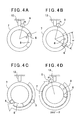
- the rotation of the rotary cam 7 is restricted by engagement of the rotary dog 9, which is rotated integrally with the rotary cam 7, and the stopper 13, and the rotary dog 9 is rotated from a position A to a position B. Because the rotation is restricted when the rotary dog 9 comes in contact with both sides of the stopper 13, as shown in the figure, maximum rotation angle of the rotary cam 7 will be: 360° - ⁇ , and the rotary cam 7 is not rotated by 360° as a single unit ( FIG.3A ).
- the fixing ring 5 is rotated by relative rotation from a position C to a position D with respect to the rotary cam 7 within a range of rotation of the position finding dog 6 in the cutaway portion 8.
- Rotation angle of the position finding dog 6 within the cutaway portion 8 is an angle, which is obtained when the angle of the cutaway portion 8 is subtracted by a portion occupied by the position finding dog 6. The angle is shown as ⁇ in the figure. ( FIG.3B )
- rotation amount of the fixing ring 5 including the rotation amount of the rotary cam 7 will be (360° - ⁇ + ⁇ ). If ⁇ is set as ⁇ ⁇ ⁇ , the fixing ring 5 can rotate by 360° or more.
- FIG.4A shows a condition when the rotation angle is 0°.
- the rotary dog 9 comes in contact with the right side in the figure of the stopper 13, and the position finding dog 6 comes in contact with an end in counterclockwise rotary direction of the cutaway portion 8.
- the rotation angle of the rotation shaft 3 is set to (360° - ⁇ + ⁇ ).
- the position finding switch 12 detects the cutaway portion 8, and based on the detection result of the position finding switch 12, reversal position of the rotation shaft 3 is judged. Therefore, in a case where the stopper 13 is rotated by motor, by controlling the motor based on a detection signal from the position finding switch 12, reverse control of the motor can be carried out even when the rotary dog 9 is not mechanically brought into contact with the stopper 13.
- FIG.5 description will be given on an inner diameter measuring device as an example of a rotation machine where the rotation restricting device according to the present embodiment is applied.
- the same component as shown in FIG.1 is referred by the same symbol.
- An inner diameter measuring head 21 is mounted on the rotary flange 4, and the inner diameter measuring head 21 is rotatably supported on the rotation unit supporting mechanism 1. Description will be given now on the inner diameter measuring head 21.
- a circulation base plate 22 is concentrically fixed on the rotary flange 4, and a measuring unit supporting base plate 23 is set in parallel to rotation axis on the circulation base plate 22.
- a measuring unit holder 25 is installed via a sliding guide 24 on the measuring unit supporting base plate 23 so that the measuring unit holder 25 can move back and forth in diametrical direction.
- a contact type measuring unit 26 is supported on the measuring unit holder 25.
- a rack 27 is disposed in parallel to the sliding guide 24, and a pinion gear 31 as mounted on output shaft of an advancing/ retreating motor 28 is engaged on the rack 27.
- the advancing/retreating motor 28 is integrated with the measuring unit holder 25, and when the advancing/retreating motor 28 rotates the pinion gear 31, the advancing/retreating motor 28 is advanced or retreated in diametrical direction together with the measuring unit holder 25 and the contact type measuring unit 26.
- reference numeral 29 denotes a contact of the contact type measuring unit 26.
- a scale sensor 33 is provided to move integrally with the measuring unit holder 25.
- a linear scale 34 is disposed at a position opposite to the scale sensor 33. When the linear scale 34 is read by the scale sensor 33, position in diametrical direction of the contact type measuring unit 26 can be determined.
- the inner diameter measuring head 21 is supported by the rotation unit supporting mechanism 1 so that the inner diameter measuring head 21 can be rotated at an angle of 360° or more, and the inner diameter measuring head 21 can be rotated and driven within the range as restricted by the rotation unit supporting mechanism 1 by means of the rotation motor 18.
- the inner diameter measuring head 21 is supported concentrically with the pipe and the inner diameter measuring head 21 is inserted into the pipe, and the contact type measuring unit 26 is moved by the advancing/ retreating motor 28 so that the contact 29 is brought into contact with the inner surface of the pipe.
- Position of the contact type measuring unit 26 is detected by the scale sensor 33. Further, when displacement of the contact 29 is detected by the contact type measuring unit 26, a position in diametrical direction where the contact 29 is brought into contact is measured. Position in peripheral direction is measured by detecting the rotation angle of the measuring unit supporting base plate 23.
- a rotation restricting device for rotation machine comprises a rotation shaft supporting body, a rotation shaft rotatably provided on the rotation shaft supporting body, a fixing ring fixed on an end portion of the rotation shaft, a position finding dog provided on the fixing ring, a rotary cam rotatably provided on the rotation shaft and disposed as relatively rotatable with respect to the fixing ring, a cutaway portion formed on the rotary cam, a rotary dog disposed on the rotary cam, and a stopper provided on the rotation shaft supporting body, wherein the position finding dog is accommodated in the cutaway portion and can be rotated within a range in space as formed by the cutaway portion, the stopper is positioned on a locus of rotation of the rotary dog, and the rotation of the rotary cam is restricted when the rotary dog comes in contact with the stopper.
- the rotation angle of the rotation shaft is a sum of the rotation angle of the rotary cam itself and the relative rotation angle between the fixing ring and the rotary cam, and this makes
Landscapes
- Engineering & Computer Science (AREA)
- General Engineering & Computer Science (AREA)
- Mechanical Engineering (AREA)
- A Measuring Device Byusing Mechanical Method (AREA)
- Length Measuring Devices With Unspecified Measuring Means (AREA)
- Transmission Devices (AREA)
- Manipulator (AREA)
Applications Claiming Priority (2)
| Application Number | Priority Date | Filing Date | Title |
|---|---|---|---|
| JP2012026048A JP5821675B2 (ja) | 2012-02-09 | 2012-02-09 | 回転機器の回転制限装置 |
| PCT/JP2013/053603 WO2013118920A1 (fr) | 2012-02-09 | 2013-02-07 | Dispositif de restriction rotationnelle pour appareil rotatif |
Publications (3)
| Publication Number | Publication Date |
|---|---|
| EP2813731A1 true EP2813731A1 (fr) | 2014-12-17 |
| EP2813731A4 EP2813731A4 (fr) | 2015-11-11 |
| EP2813731B1 EP2813731B1 (fr) | 2018-05-09 |
Family
ID=48947668
Family Applications (1)
| Application Number | Title | Priority Date | Filing Date |
|---|---|---|---|
| EP13746993.8A Active EP2813731B1 (fr) | 2012-02-09 | 2013-02-07 | Dispositif de restriction rotationnelle pour appareil rotatif |
Country Status (4)
| Country | Link |
|---|---|
| US (1) | US9145924B2 (fr) |
| EP (1) | EP2813731B1 (fr) |
| JP (1) | JP5821675B2 (fr) |
| WO (1) | WO2013118920A1 (fr) |
Cited By (1)
| Publication number | Priority date | Publication date | Assignee | Title |
|---|---|---|---|---|
| FR3066629A1 (fr) * | 2017-05-18 | 2018-11-23 | Thales | Dispositif mecanique a butees rotatives a amplitude de rotation superieure a un tour |
Families Citing this family (14)
| Publication number | Priority date | Publication date | Assignee | Title |
|---|---|---|---|---|
| WO2013118912A1 (fr) | 2012-02-09 | 2013-08-15 | 株式会社Ihi | Dispositif de mesure de diamètre intérieur |
| US9372061B2 (en) | 2012-02-09 | 2016-06-21 | Ihi Corporation | Inner diameter measuring device |
| JP2013164274A (ja) | 2012-02-09 | 2013-08-22 | Ihi Corp | 内径測定装置 |
| JP5915223B2 (ja) | 2012-02-09 | 2016-05-11 | 株式会社Ihi | 内径測定装置及び内径測定方法 |
| JP5880096B2 (ja) | 2012-02-09 | 2016-03-08 | 株式会社Ihi | 内径測定装置 |
| JP5880097B2 (ja) | 2012-02-09 | 2016-03-08 | 株式会社Ihi | 内径測定装置 |
| JP5915222B2 (ja) | 2012-02-09 | 2016-05-11 | 株式会社Ihi | 内径測定装置 |
| JP6415214B2 (ja) * | 2014-09-26 | 2018-10-31 | 株式会社シブタニ | トイレブースにおけるドアの開閉装置 |
| KR102332109B1 (ko) * | 2017-04-06 | 2021-11-30 | 두산공작기계 주식회사 | 공작기계 |
| CN107283013B (zh) * | 2017-06-30 | 2019-07-30 | 上海工程技术大学 | 一种用于加工石油井用卡套的定位分度装置及加工方法 |
| TW202004403A (zh) | 2018-06-01 | 2020-01-16 | 和碩聯合科技股份有限公司 | 旋轉裝置 |
| CN110792688B (zh) * | 2019-09-24 | 2021-03-05 | 华为技术有限公司 | 一种铰链结构及可折叠电子设备 |
| CA3172896A1 (fr) | 2020-03-27 | 2021-09-30 | Breese J. Watson | Module d'appareil de prise de vue a rotation a 360 degres et plus pour poignee de tete d'eclairage chirurgical |
| KR102624062B1 (ko) * | 2022-09-30 | 2024-01-11 | 김주훈 | 공작기계용 컨트롤러 장치 |
Family Cites Families (56)
| Publication number | Priority date | Publication date | Assignee | Title |
|---|---|---|---|---|
| US1664851A (en) * | 1926-08-18 | 1928-04-03 | Gisholt Machine Co | Tool post |
| US1721524A (en) * | 1927-10-03 | 1929-07-23 | Charles E Moore | Feed-screw limit gauge for lathes |
| US3247732A (en) * | 1963-10-16 | 1966-04-26 | A E Moore Company Inc | Reversible drive mechanism |
| US3436967A (en) * | 1965-08-18 | 1969-04-08 | Aircraft Radio Corp | Mechanical suppressor for jittery shaft |
| JPS50159355A (fr) | 1974-06-12 | 1975-12-23 | ||
| IT1133314B (it) | 1980-06-02 | 1986-07-09 | Finike Italiana Marposs | Comparatore manuale a tampone per il controllo del diametro di fori |
| JPS5866809A (ja) | 1981-09-28 | 1983-04-21 | サミユエル・ロスステイン | 管の欠陥測定方法及び管の検査装置における複合走査装置 |
| JPS59187155A (ja) | 1983-04-06 | 1984-10-24 | Hitachi Ltd | 回転運動変換装置 |
| JPS61144551A (ja) | 1984-12-18 | 1986-07-02 | Toshiba Corp | 長孔周壁検査装置 |
| JPS61282659A (ja) | 1985-06-10 | 1986-12-12 | Fuji Electric Co Ltd | 回動軸の回動範囲制限機構 |
| JPH0733996B2 (ja) | 1986-08-26 | 1995-04-12 | 三菱電機株式会社 | 管内面形状検出装置 |
| JPS63159708A (ja) | 1986-12-24 | 1988-07-02 | Seiko Instr & Electronics Ltd | 円筒形状物の軸中心検出装置 |
| JPH01195309A (ja) | 1988-01-29 | 1989-08-07 | Sumitomo Rubber Ind Ltd | 円筒体測定装置 |
| DE3841439A1 (de) | 1988-12-09 | 1990-06-13 | Pietzsch Automatisierungstech | Vorrichtung zum gleichzeitigen vermessen hintereinanderliegender zylinderbohrungen |
| JP2531488B2 (ja) | 1993-08-10 | 1996-09-04 | 株式会社機動技研 | 管内測定方法 |
| JPH0729405U (ja) | 1993-11-01 | 1995-06-02 | 三菱重工業株式会社 | 管内面検査装置 |
| JPH07191269A (ja) | 1993-12-27 | 1995-07-28 | Y S Opt:Kk | 内面観察装置 |
| JPH0814874A (ja) | 1994-06-27 | 1996-01-19 | Tosok Corp | 測定装置 |
| JPH0893876A (ja) | 1994-09-28 | 1996-04-12 | Mitsubishi Heavy Ind Ltd | 回転軸の過回動防止構造 |
| JP3338571B2 (ja) * | 1994-11-22 | 2002-10-28 | アスモ株式会社 | 移動体の位置検出装置 |
| JP3502491B2 (ja) | 1995-12-13 | 2004-03-02 | 本田技研工業株式会社 | 金型およびその製造方法 |
| JPH09311034A (ja) | 1996-05-23 | 1997-12-02 | Sumitomo Metal Ind Ltd | 鋼管の内径・内周長測定方法及び装置 |
| JPH10197215A (ja) | 1996-12-19 | 1998-07-31 | Westinghouse Electric Corp <We> | 管状製品の内壁の光学検査装置 |
| JP3700805B2 (ja) | 1997-01-30 | 2005-09-28 | 石川島播磨重工業株式会社 | ロングシャフトの内径振れ計測装置 |
| JP2000146564A (ja) | 1998-11-04 | 2000-05-26 | Kubota Corp | 接触式管内径測定装置の精度確認装置 |
| JP2000136923A (ja) | 1998-11-04 | 2000-05-16 | Kubota Corp | 接触式管内径測定装置 |
| JP2002022671A (ja) | 2000-07-12 | 2002-01-23 | Nissan Motor Co Ltd | 円筒内壁面検査装置および検査方法 |
| JP2002148036A (ja) | 2000-11-10 | 2002-05-22 | Mitsubishi Heavy Ind Ltd | 管内径モニタリング装置 |
| JP4085616B2 (ja) | 2001-11-01 | 2008-05-14 | 株式会社日立プラントテクノロジー | 内面形状計測方法及びその装置 |
| US6931149B2 (en) | 2002-04-19 | 2005-08-16 | Norsk Elektro Optikk A/S | Pipeline internal inspection device and method |
| JP2003329606A (ja) | 2002-05-09 | 2003-11-19 | Tohoku Techno Arch Co Ltd | 内面検査装置 |
| JP3869360B2 (ja) * | 2002-12-27 | 2007-01-17 | 三鷹光器株式会社 | 手術用顕微鏡の回転支持構造 |
| JP2004176852A (ja) | 2002-11-28 | 2004-06-24 | Moriyama Giken:Kk | 回転体ストッパーとそれを用いた風力発電装置 |
| JP4230408B2 (ja) | 2004-04-30 | 2009-02-25 | 独立行政法人科学技術振興機構 | 深穴計測装置および深穴計測方法 |
| JP2005331333A (ja) | 2004-05-19 | 2005-12-02 | Mitsubishi Heavy Ind Ltd | 軸管内径計測装置および軸管内径自動計測装置 |
| JP3105724U (ja) | 2004-06-04 | 2004-11-25 | 株式会社環境システム | 管の内径測定装置 |
| US7189023B2 (en) * | 2004-09-01 | 2007-03-13 | Micro-Star Int'l Co., Ltd. | Rotational positioning apparatus |
| JP2006153546A (ja) | 2004-11-26 | 2006-06-15 | Sanyo Special Steel Co Ltd | 接触式鋼管寸法測定装置 |
| JP4508849B2 (ja) * | 2004-11-30 | 2010-07-21 | 株式会社ケンウッド | 回転つまみのストッパー構造 |
| JP4192901B2 (ja) | 2005-02-17 | 2008-12-10 | 三菱電機株式会社 | アンテナ装置 |
| JP4641824B2 (ja) | 2005-02-24 | 2011-03-02 | 株式会社クボタ | 管内調査装置 |
| JP2007057305A (ja) | 2005-08-23 | 2007-03-08 | Mitsubishi Electric Engineering Co Ltd | 筒内検査装置 |
| JP2007071852A (ja) | 2005-09-02 | 2007-03-22 | Akio Katsuki | 深穴測定装置および深穴測定方法 |
| CH705706B1 (de) * | 2005-11-03 | 2013-05-15 | Belimo Holding Ag | Stellantrieb mit einem Reduktionsgetriebe für ein Stellglied zur Regelung eines Gas- oder Flüssigkeitsstroms. |
| FR2898671B1 (fr) | 2006-03-14 | 2008-12-26 | Snecma Sa | Systeme de mesure de cotes a l'interieur d'un arbre creux notamment de turbomachine aeronautique |
| JP2007292699A (ja) | 2006-04-27 | 2007-11-08 | Asmo Co Ltd | 部材の表面検査方法 |
| JP2010164334A (ja) | 2009-01-13 | 2010-07-29 | Ihi Corp | 内面形状測定装置および内面形状測定方法 |
| JP2011002439A (ja) | 2009-06-22 | 2011-01-06 | Kentaro Iguchi | 検査装置 |
| JP5378083B2 (ja) | 2009-07-01 | 2013-12-25 | 東亜グラウト工業株式会社 | 内径測定装置及びその内径測定装置を用いた管路内径測定システム |
| JP5880096B2 (ja) | 2012-02-09 | 2016-03-08 | 株式会社Ihi | 内径測定装置 |
| JP5880097B2 (ja) | 2012-02-09 | 2016-03-08 | 株式会社Ihi | 内径測定装置 |
| JP5915223B2 (ja) | 2012-02-09 | 2016-05-11 | 株式会社Ihi | 内径測定装置及び内径測定方法 |
| JP5915222B2 (ja) | 2012-02-09 | 2016-05-11 | 株式会社Ihi | 内径測定装置 |
| JP2013164274A (ja) | 2012-02-09 | 2013-08-22 | Ihi Corp | 内径測定装置 |
| WO2013118912A1 (fr) | 2012-02-09 | 2013-08-15 | 株式会社Ihi | Dispositif de mesure de diamètre intérieur |
| US9372061B2 (en) | 2012-02-09 | 2016-06-21 | Ihi Corporation | Inner diameter measuring device |
-
2012
- 2012-02-09 JP JP2012026048A patent/JP5821675B2/ja active Active
-
2013
- 2013-02-07 EP EP13746993.8A patent/EP2813731B1/fr active Active
- 2013-02-07 US US14/377,225 patent/US9145924B2/en active Active
- 2013-02-07 WO PCT/JP2013/053603 patent/WO2013118920A1/fr active Application Filing
Cited By (1)
| Publication number | Priority date | Publication date | Assignee | Title |
|---|---|---|---|---|
| FR3066629A1 (fr) * | 2017-05-18 | 2018-11-23 | Thales | Dispositif mecanique a butees rotatives a amplitude de rotation superieure a un tour |
Also Published As
| Publication number | Publication date |
|---|---|
| US9145924B2 (en) | 2015-09-29 |
| WO2013118920A1 (fr) | 2013-08-15 |
| EP2813731A4 (fr) | 2015-11-11 |
| JP5821675B2 (ja) | 2015-11-24 |
| US20150000465A1 (en) | 2015-01-01 |
| JP2013164087A (ja) | 2013-08-22 |
| EP2813731B1 (fr) | 2018-05-09 |
Similar Documents
| Publication | Publication Date | Title |
|---|---|---|
| EP2813731B1 (fr) | Dispositif de restriction rotationnelle pour appareil rotatif | |
| JP5296541B2 (ja) | 車両のための電動補助駆動装置 | |
| EP2182329B1 (fr) | Encodeur rotatif de détection par induction | |
| US7584551B2 (en) | Absolute position measuring apparatus | |
| CN107816929B (zh) | 圆度测量机 | |
| EP2352620B1 (fr) | Unité de broche | |
| EP3239654B1 (fr) | Dispositif de mesure de rotondité | |
| CN101699221A (zh) | 可实现360°范围内转动的转台限位机构 | |
| US9574611B2 (en) | Roller bearing having sensor, motor, and actuator | |
| WO2006112077A1 (fr) | Robot industriel | |
| EP3163590B1 (fr) | Dispositif de positionnement de bobine | |
| KR101999267B1 (ko) | 축방향력의 측정이 가능한 나사 구동장치 | |
| US10116110B2 (en) | Rotor arrangement for a slip ring assembly and rotary coupling arrangement comprising a rotor arrangement of this kind | |
| CN211042090U (zh) | 一种转轴定位装置 | |
| KR930016780A (ko) | 360˚감지가 가능한 센서 회전장치 | |
| FR3080679B1 (fr) | Dispositif de detection de la position angulaire d'un rotor d'une machine electrique tournante | |
| JP5436390B2 (ja) | 可変プーリのバックラッシュ測定装置 | |
| JP3035881B2 (ja) | 可搬式真円度測定器 | |
| CN202158139U (zh) | 带可控装置的蜗轮蜗杆传动单元 | |
| JP4417340B2 (ja) | 輸液装置の原動機保持機構 | |
| CN109596430B (zh) | 重载精密转台 | |
| CN202582457U (zh) | 测角仪 | |
| JP5080181B2 (ja) | 磁極検出器付き同期電動機 | |
| JP2008249136A (ja) | 回転センサの径方向平面配置構造を有する転がり軸受装置 | |
| KR101619817B1 (ko) | 보링 공구 |
Legal Events
| Date | Code | Title | Description |
|---|---|---|---|
| PUAI | Public reference made under article 153(3) epc to a published international application that has entered the european phase |
Free format text: ORIGINAL CODE: 0009012 |
|
| 17P | Request for examination filed |
Effective date: 20140728 |
|
| AK | Designated contracting states |
Kind code of ref document: A1 Designated state(s): AL AT BE BG CH CY CZ DE DK EE ES FI FR GB GR HR HU IE IS IT LI LT LU LV MC MK MT NL NO PL PT RO RS SE SI SK SM TR |
|
| AX | Request for extension of the european patent |
Extension state: BA ME |
|
| DAX | Request for extension of the european patent (deleted) | ||
| RA4 | Supplementary search report drawn up and despatched (corrected) |
Effective date: 20151008 |
|
| RIC1 | Information provided on ipc code assigned before grant |
Ipc: F16H 35/14 20060101ALI20151002BHEP Ipc: G01B 5/12 20060101ALI20151002BHEP Ipc: F16H 35/00 20060101AFI20151002BHEP Ipc: F16M 11/06 20060101ALI20151002BHEP |
|
| RIC1 | Information provided on ipc code assigned before grant |
Ipc: G01B 5/12 20060101ALI20171010BHEP Ipc: F16M 11/06 20060101ALI20171010BHEP Ipc: F16H 35/14 20060101ALI20171010BHEP Ipc: F16H 35/00 20060101AFI20171010BHEP Ipc: F16M 11/20 20060101ALI20171010BHEP |
|
| GRAP | Despatch of communication of intention to grant a patent |
Free format text: ORIGINAL CODE: EPIDOSNIGR1 |
|
| STAA | Information on the status of an ep patent application or granted ep patent |
Free format text: STATUS: GRANT OF PATENT IS INTENDED |
|
| INTG | Intention to grant announced |
Effective date: 20171208 |
|
| RIN1 | Information on inventor provided before grant (corrected) |
Inventor name: BABA, MICHIKO Inventor name: MIURA, YUUICHI Inventor name: TAGA, NORIMASA Inventor name: HASEGAWA, KOUZOU |
|
| GRAS | Grant fee paid |
Free format text: ORIGINAL CODE: EPIDOSNIGR3 |
|
| GRAA | (expected) grant |
Free format text: ORIGINAL CODE: 0009210 |
|
| STAA | Information on the status of an ep patent application or granted ep patent |
Free format text: STATUS: THE PATENT HAS BEEN GRANTED |
|
| AK | Designated contracting states |
Kind code of ref document: B1 Designated state(s): AL AT BE BG CH CY CZ DE DK EE ES FI FR GB GR HR HU IE IS IT LI LT LU LV MC MK MT NL NO PL PT RO RS SE SI SK SM TR |
|
| REG | Reference to a national code |
Ref country code: GB Ref legal event code: FG4D |
|
| REG | Reference to a national code |
Ref country code: CH Ref legal event code: EP Ref country code: AT Ref legal event code: REF Ref document number: 997857 Country of ref document: AT Kind code of ref document: T Effective date: 20180515 |
|
| REG | Reference to a national code |
Ref country code: IE Ref legal event code: FG4D |
|
| REG | Reference to a national code |
Ref country code: DE Ref legal event code: R096 Ref document number: 602013037238 Country of ref document: DE |
|
| REG | Reference to a national code |
Ref country code: NL Ref legal event code: MP Effective date: 20180509 |
|
| REG | Reference to a national code |
Ref country code: LT Ref legal event code: MG4D |
|
| PG25 | Lapsed in a contracting state [announced via postgrant information from national office to epo] |
Ref country code: FI Free format text: LAPSE BECAUSE OF FAILURE TO SUBMIT A TRANSLATION OF THE DESCRIPTION OR TO PAY THE FEE WITHIN THE PRESCRIBED TIME-LIMIT Effective date: 20180509 Ref country code: LT Free format text: LAPSE BECAUSE OF FAILURE TO SUBMIT A TRANSLATION OF THE DESCRIPTION OR TO PAY THE FEE WITHIN THE PRESCRIBED TIME-LIMIT Effective date: 20180509 Ref country code: BG Free format text: LAPSE BECAUSE OF FAILURE TO SUBMIT A TRANSLATION OF THE DESCRIPTION OR TO PAY THE FEE WITHIN THE PRESCRIBED TIME-LIMIT Effective date: 20180809 Ref country code: ES Free format text: LAPSE BECAUSE OF FAILURE TO SUBMIT A TRANSLATION OF THE DESCRIPTION OR TO PAY THE FEE WITHIN THE PRESCRIBED TIME-LIMIT Effective date: 20180509 Ref country code: SE Free format text: LAPSE BECAUSE OF FAILURE TO SUBMIT A TRANSLATION OF THE DESCRIPTION OR TO PAY THE FEE WITHIN THE PRESCRIBED TIME-LIMIT Effective date: 20180509 Ref country code: NO Free format text: LAPSE BECAUSE OF FAILURE TO SUBMIT A TRANSLATION OF THE DESCRIPTION OR TO PAY THE FEE WITHIN THE PRESCRIBED TIME-LIMIT Effective date: 20180809 |
|
| PG25 | Lapsed in a contracting state [announced via postgrant information from national office to epo] |
Ref country code: GR Free format text: LAPSE BECAUSE OF FAILURE TO SUBMIT A TRANSLATION OF THE DESCRIPTION OR TO PAY THE FEE WITHIN THE PRESCRIBED TIME-LIMIT Effective date: 20180810 Ref country code: HR Free format text: LAPSE BECAUSE OF FAILURE TO SUBMIT A TRANSLATION OF THE DESCRIPTION OR TO PAY THE FEE WITHIN THE PRESCRIBED TIME-LIMIT Effective date: 20180509 Ref country code: RS Free format text: LAPSE BECAUSE OF FAILURE TO SUBMIT A TRANSLATION OF THE DESCRIPTION OR TO PAY THE FEE WITHIN THE PRESCRIBED TIME-LIMIT Effective date: 20180509 Ref country code: LV Free format text: LAPSE BECAUSE OF FAILURE TO SUBMIT A TRANSLATION OF THE DESCRIPTION OR TO PAY THE FEE WITHIN THE PRESCRIBED TIME-LIMIT Effective date: 20180509 Ref country code: NL Free format text: LAPSE BECAUSE OF FAILURE TO SUBMIT A TRANSLATION OF THE DESCRIPTION OR TO PAY THE FEE WITHIN THE PRESCRIBED TIME-LIMIT Effective date: 20180509 |
|
| REG | Reference to a national code |
Ref country code: AT Ref legal event code: MK05 Ref document number: 997857 Country of ref document: AT Kind code of ref document: T Effective date: 20180509 |
|
| PG25 | Lapsed in a contracting state [announced via postgrant information from national office to epo] |
Ref country code: DK Free format text: LAPSE BECAUSE OF FAILURE TO SUBMIT A TRANSLATION OF THE DESCRIPTION OR TO PAY THE FEE WITHIN THE PRESCRIBED TIME-LIMIT Effective date: 20180509 Ref country code: PL Free format text: LAPSE BECAUSE OF FAILURE TO SUBMIT A TRANSLATION OF THE DESCRIPTION OR TO PAY THE FEE WITHIN THE PRESCRIBED TIME-LIMIT Effective date: 20180509 Ref country code: CZ Free format text: LAPSE BECAUSE OF FAILURE TO SUBMIT A TRANSLATION OF THE DESCRIPTION OR TO PAY THE FEE WITHIN THE PRESCRIBED TIME-LIMIT Effective date: 20180509 Ref country code: SK Free format text: LAPSE BECAUSE OF FAILURE TO SUBMIT A TRANSLATION OF THE DESCRIPTION OR TO PAY THE FEE WITHIN THE PRESCRIBED TIME-LIMIT Effective date: 20180509 Ref country code: RO Free format text: LAPSE BECAUSE OF FAILURE TO SUBMIT A TRANSLATION OF THE DESCRIPTION OR TO PAY THE FEE WITHIN THE PRESCRIBED TIME-LIMIT Effective date: 20180509 Ref country code: EE Free format text: LAPSE BECAUSE OF FAILURE TO SUBMIT A TRANSLATION OF THE DESCRIPTION OR TO PAY THE FEE WITHIN THE PRESCRIBED TIME-LIMIT Effective date: 20180509 Ref country code: AT Free format text: LAPSE BECAUSE OF FAILURE TO SUBMIT A TRANSLATION OF THE DESCRIPTION OR TO PAY THE FEE WITHIN THE PRESCRIBED TIME-LIMIT Effective date: 20180509 |
|
| REG | Reference to a national code |
Ref country code: DE Ref legal event code: R097 Ref document number: 602013037238 Country of ref document: DE |
|
| PG25 | Lapsed in a contracting state [announced via postgrant information from national office to epo] |
Ref country code: SM Free format text: LAPSE BECAUSE OF FAILURE TO SUBMIT A TRANSLATION OF THE DESCRIPTION OR TO PAY THE FEE WITHIN THE PRESCRIBED TIME-LIMIT Effective date: 20180509 Ref country code: IT Free format text: LAPSE BECAUSE OF FAILURE TO SUBMIT A TRANSLATION OF THE DESCRIPTION OR TO PAY THE FEE WITHIN THE PRESCRIBED TIME-LIMIT Effective date: 20180509 |
|
| PLBE | No opposition filed within time limit |
Free format text: ORIGINAL CODE: 0009261 |
|
| STAA | Information on the status of an ep patent application or granted ep patent |
Free format text: STATUS: NO OPPOSITION FILED WITHIN TIME LIMIT |
|
| 26N | No opposition filed |
Effective date: 20190212 |
|
| PG25 | Lapsed in a contracting state [announced via postgrant information from national office to epo] |
Ref country code: SI Free format text: LAPSE BECAUSE OF FAILURE TO SUBMIT A TRANSLATION OF THE DESCRIPTION OR TO PAY THE FEE WITHIN THE PRESCRIBED TIME-LIMIT Effective date: 20180509 |
|
| REG | Reference to a national code |
Ref country code: CH Ref legal event code: PL |
|
| PG25 | Lapsed in a contracting state [announced via postgrant information from national office to epo] |
Ref country code: MC Free format text: LAPSE BECAUSE OF FAILURE TO SUBMIT A TRANSLATION OF THE DESCRIPTION OR TO PAY THE FEE WITHIN THE PRESCRIBED TIME-LIMIT Effective date: 20180509 Ref country code: LU Free format text: LAPSE BECAUSE OF NON-PAYMENT OF DUE FEES Effective date: 20190207 |
|
| REG | Reference to a national code |
Ref country code: BE Ref legal event code: MM Effective date: 20190228 |
|
| REG | Reference to a national code |
Ref country code: IE Ref legal event code: MM4A |
|
| PG25 | Lapsed in a contracting state [announced via postgrant information from national office to epo] |
Ref country code: AL Free format text: LAPSE BECAUSE OF FAILURE TO SUBMIT A TRANSLATION OF THE DESCRIPTION OR TO PAY THE FEE WITHIN THE PRESCRIBED TIME-LIMIT Effective date: 20180509 |
|
| PG25 | Lapsed in a contracting state [announced via postgrant information from national office to epo] |
Ref country code: CH Free format text: LAPSE BECAUSE OF NON-PAYMENT OF DUE FEES Effective date: 20190228 Ref country code: LI Free format text: LAPSE BECAUSE OF NON-PAYMENT OF DUE FEES Effective date: 20190228 |
|
| PG25 | Lapsed in a contracting state [announced via postgrant information from national office to epo] |
Ref country code: IE Free format text: LAPSE BECAUSE OF NON-PAYMENT OF DUE FEES Effective date: 20190207 |
|
| PG25 | Lapsed in a contracting state [announced via postgrant information from national office to epo] |
Ref country code: BE Free format text: LAPSE BECAUSE OF NON-PAYMENT OF DUE FEES Effective date: 20190228 |
|
| PG25 | Lapsed in a contracting state [announced via postgrant information from national office to epo] |
Ref country code: TR Free format text: LAPSE BECAUSE OF FAILURE TO SUBMIT A TRANSLATION OF THE DESCRIPTION OR TO PAY THE FEE WITHIN THE PRESCRIBED TIME-LIMIT Effective date: 20180509 |
|
| PG25 | Lapsed in a contracting state [announced via postgrant information from national office to epo] |
Ref country code: PT Free format text: LAPSE BECAUSE OF FAILURE TO SUBMIT A TRANSLATION OF THE DESCRIPTION OR TO PAY THE FEE WITHIN THE PRESCRIBED TIME-LIMIT Effective date: 20180910 Ref country code: MT Free format text: LAPSE BECAUSE OF NON-PAYMENT OF DUE FEES Effective date: 20190207 |
|
| PG25 | Lapsed in a contracting state [announced via postgrant information from national office to epo] |
Ref country code: CY Free format text: LAPSE BECAUSE OF FAILURE TO SUBMIT A TRANSLATION OF THE DESCRIPTION OR TO PAY THE FEE WITHIN THE PRESCRIBED TIME-LIMIT Effective date: 20180509 |
|
| PG25 | Lapsed in a contracting state [announced via postgrant information from national office to epo] |
Ref country code: IS Free format text: LAPSE BECAUSE OF FAILURE TO SUBMIT A TRANSLATION OF THE DESCRIPTION OR TO PAY THE FEE WITHIN THE PRESCRIBED TIME-LIMIT Effective date: 20180909 |
|
| PG25 | Lapsed in a contracting state [announced via postgrant information from national office to epo] |
Ref country code: HU Free format text: LAPSE BECAUSE OF FAILURE TO SUBMIT A TRANSLATION OF THE DESCRIPTION OR TO PAY THE FEE WITHIN THE PRESCRIBED TIME-LIMIT; INVALID AB INITIO Effective date: 20130207 |
|
| PG25 | Lapsed in a contracting state [announced via postgrant information from national office to epo] |
Ref country code: MK Free format text: LAPSE BECAUSE OF FAILURE TO SUBMIT A TRANSLATION OF THE DESCRIPTION OR TO PAY THE FEE WITHIN THE PRESCRIBED TIME-LIMIT Effective date: 20180509 |
|
| PGFP | Annual fee paid to national office [announced via postgrant information from national office to epo] |
Ref country code: FR Payment date: 20230119 Year of fee payment: 11 |
|
| PGFP | Annual fee paid to national office [announced via postgrant information from national office to epo] |
Ref country code: GB Payment date: 20230120 Year of fee payment: 11 Ref country code: DE Payment date: 20230119 Year of fee payment: 11 |
|
| PGFP | Annual fee paid to national office [announced via postgrant information from national office to epo] |
Ref country code: DE Payment date: 20240123 Year of fee payment: 12 Ref country code: GB Payment date: 20240123 Year of fee payment: 12 |