EP2808875B1 - Integrierte Kabelverdrillungs-, Kabelumhüllungs- und Kabeltestvorrichtung und Betriebsverfahren dafür - Google Patents
Integrierte Kabelverdrillungs-, Kabelumhüllungs- und Kabeltestvorrichtung und Betriebsverfahren dafür Download PDFInfo
- Publication number
- EP2808875B1 EP2808875B1 EP14169294.7A EP14169294A EP2808875B1 EP 2808875 B1 EP2808875 B1 EP 2808875B1 EP 14169294 A EP14169294 A EP 14169294A EP 2808875 B1 EP2808875 B1 EP 2808875B1
- Authority
- EP
- European Patent Office
- Prior art keywords
- clamp
- tape
- wire pair
- wire
- pair
- Prior art date
- Legal status (The legal status is an assumption and is not a legal conclusion. Google has not performed a legal analysis and makes no representation as to the accuracy of the status listed.)
- Active
Links
Images


Classifications
-
- H—ELECTRICITY
- H01—ELECTRIC ELEMENTS
- H01B—CABLES; CONDUCTORS; INSULATORS; SELECTION OF MATERIALS FOR THEIR CONDUCTIVE, INSULATING OR DIELECTRIC PROPERTIES
- H01B13/00—Apparatus or processes specially adapted for manufacturing conductors or cables
- H01B13/22—Sheathing; Armouring; Screening; Applying other protective layers
- H01B13/26—Sheathing; Armouring; Screening; Applying other protective layers by winding, braiding or longitudinal lapping
-
- H—ELECTRICITY
- H01—ELECTRIC ELEMENTS
- H01B—CABLES; CONDUCTORS; INSULATORS; SELECTION OF MATERIALS FOR THEIR CONDUCTIVE, INSULATING OR DIELECTRIC PROPERTIES
- H01B13/00—Apparatus or processes specially adapted for manufacturing conductors or cables
- H01B13/02—Stranding-up
-
- H—ELECTRICITY
- H01—ELECTRIC ELEMENTS
- H01B—CABLES; CONDUCTORS; INSULATORS; SELECTION OF MATERIALS FOR THEIR CONDUCTIVE, INSULATING OR DIELECTRIC PROPERTIES
- H01B13/00—Apparatus or processes specially adapted for manufacturing conductors or cables
- H01B13/06—Insulating conductors or cables
- H01B13/08—Insulating conductors or cables by winding
- H01B13/085—Apparatus having the supply reels in a fixed position, the conductor or cable rotating about its own axis
-
- H—ELECTRICITY
- H01—ELECTRIC ELEMENTS
- H01B—CABLES; CONDUCTORS; INSULATORS; SELECTION OF MATERIALS FOR THEIR CONDUCTIVE, INSULATING OR DIELECTRIC PROPERTIES
- H01B13/00—Apparatus or processes specially adapted for manufacturing conductors or cables
- H01B13/22—Sheathing; Armouring; Screening; Applying other protective layers
- H01B13/227—Pretreatment
Definitions
- the invention generally relates to electrical wire cable manufacturing machines, and more particularly relates to a machine configured to automatically twist and wrap a twisted pair cable.
- Twisted wire pair cables used in automotive wire harnesses may also include an uninsulated "drain" wire and are wrapped in a conductive tape or foil that provides an electromagnetic shield. The conductive tape is then overwrapped with an insulative tape.
- a post twister machine that twists two or more wires to have a specific pitch or number of twists per unit length, e.g. twists per meter.
- the twisted wire pair along with the drain wire are then run through a dual taper machine, so named because it applies both the conductive tape and insulative tape to the wires at the same time.
- the dual taper machine spirally wraps the wires with the conductive tape and insulative tape.
- the dual taper machine typically uses feed wheels to pull the wires through the machine as the tape is applied.
- the pressure of the feed wheels on the wire pair provides an opportunity to damage the twisted wire pair.
- the operator may be required to pull the twisted pair wires though the dual taper machine before the feed wheels are engaged, providing another opportunity for damage.
- the drain wire is typically fed into the dual taper machine from a spool. As the wires are pulled through the dual taper machine the drain wire can tangle and become wrapped around the wire pair in such a way as to pinch through the insulation of the wire pair, causing a product failure.
- Damage to the insulated twisted wire pair that occurs during the manufacturing process or prior to the manufacturing process can create a failure when the wiring harness is used in the vehicle. Therefore, a facility to electrically test the twisted pair to ensure manufacturing quality is desired.
- an apparatus configured to manufacture a wire cable assembly including an insulated twisted wire pair having a tape spirally wrapped about said wire pair according to claim 1 .
- the apparatus includes a first clamp to secure a first end of the wire pair.
- the first clamp is configured to rotate or maintain a fixed position.
- the apparatus also includes a second clamp to secure a second end of the wire pair.
- the second clamp axially opposed to the first clamp.
- the second clamp is also configured to rotate while the first clamp maintains the fixed position thereby twisting the wires of the wire pair one about the other or to rotate synchronously with the rotation of the first clamp thereby rotating the wire pair without further twisting wire pair.
- the second clamp may be configured to maintain a fixed position and the first clamp may be configured to rotate while the second clamp maintains the fixed position thereby twisting the wires of the wire pair one about the other.
- the first and second clamps may be further configured to secure an uninsulated drain wire in addition to the wire pair.
- the apparatus may include a first servo motor that is mechanically coupled to the first clamp and is configured to rotate the first clamp and a second servo motor that is mechanically coupled to the second clamp and is configured to rotate the second clamp.
- the apparatus further includes a first tape reel that holds a first tape.
- the first tape reel is configured to move generally parallel to the axis of the first and second clamps when they rotate synchronously thereby wrapping the first tape around the wire pair.
- the apparatus may also include a second tape reel that holds a second tape.
- the second tape reel is configured to move in tandem with the first tape reel, thereby also wrapping the second tape around the wire pair.
- the apparatus may include a third servo motor that is mechanically coupled to the first tape reel and is configured to move the first tape reel in the direction generally parallel to the axis of the first and second clamps.
- the apparatus may also include an electrical continuity tester configured to check electrical continuity of the wire pair and drain wire after the first tape is applied.
- a method of manufacturing a wire cable assembly including an insulated twisted wire pair having a tape spirally wrapped about said wire pair according to claim 9 includes the steps of providing a first clamp configured to secure a first end of the wire pair, providing a second clamp axially opposed to the first clamp configured to secure a second end of the wire pair, and providing a first tape reel holding a first tape.
- the method also includes the steps of securing the first end in the first clamp, securing the second end in the second clamp, and attaching an end of the first tape to the wire pair proximate the first clamp.
- the method further includes the steps of rotating the second clamp while fixing the position of the first clamp, thereby twisting the wires of the wire pair one about the other, securing the end of the first tape within the wire pair, rotating the first clamp, and rotating the second clamp synchronously with the rotation of the first clamp thereby rotating the wire pair without twisting.
- the method additionally includes the steps of moving the first tape reel in a direction generally parallel to the axis of the first and second clamps as they rotate synchronously thereby wrapping the first tape around the wire pair.
- the method may also include the steps of providing a second tape reel holding a second tape, attaching an end of the second tape to the wire pair in the location proximate the first clamp, rotating the second clamp while fixing the position of the first clamp, thereby securing the end of the second tape within the wire pair, and moving the second tape reel in tandem with the first tape reel from a location proximate the first clamp to a location proximate the second clamp thereby wrapping the second tape around the wire pair.
- the method may include the step of rotating the second clamp in the opposite direction thereby relieving wire stress in the wire pair and/or the step of securing an uninsulated drain wire in the first and second clamps in addition to the wire pair
- the method may further include the steps of cutting the first and second tape and securing the cut ends of the first and second tape to the wire pair.
- the method may include the step of checking electrical continuity of the wire pair.
- a single machine designed to manufacture a wire cable assembly that includes an insulated twisted wire pair having a tape spirally wrapped about the wire pair.
- the machine is also capable of manufacturing a wire cable assembly that additionally includes a non-insulated drain wire and is additionally wrapped with an electrically conductive foil or tape to provide an electromagnetic shield around the twisted wire pair.
- a method of manufacturing this wire cable using this machine is also presented herein.
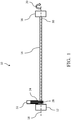
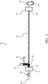
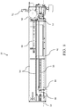
- Fig. 1 illustrates a non-limiting example of an integrated wire cable twisting, wrapping, and testing machine 10 or apparatus 10, hereafter the apparatus 10.
- the illustrations of Figs. 1-5 are schematic representations to simplify the explanation of the elements of the apparatus 10.
- Detailed illustrations of the apparatus 10 are found in Figs. 6- 10 .
- the apparatus 10 is designed to manufacture a wire cable assembly that includes an insulated twisted wire pair with a tape spirally wrapped about the wire pair. This type of wire cable is typically referred to as an unshielded twisted pair.
- the apparatus 10 includes a first wire chuck or first clamp 12 that is configured to hold or secure one end of a pair of insulated wires 14 and a second wire chuck or second clamp 16 configured to hold or secure the other end of the wire pair 14.
- the wire pair 14 is held substantially taut between the first and second clamps 12, 16.
- the first and second clamps 12, 16 may be designed to hold terminated wire ends, i.e. wire ends having terminals or contacts attached and/or the clamps may be designed to hold unterminated wire ends.
- the second clamp 16 is axially opposed to the first clamp 12.
- the first clamp 12 is constructed to be locked in a fixed position so that it does not rotate.
- the second clamp 16 is designed to rotate about the axis 18 between the first and second clamp 12, 16 the direction 20 while the first clamp 12 remains locked in the fixed position, thereby twisting the wires of the wire pair 14 one about the other.
- the number of rotations and the speed of rotation are controlled in order to provide the proper pitch or twists per unit length of the twisted wire pair 14.
- the first clamp 12 is also configured to rotate about the axis 18 between the first and second clamp 12, 16.
- the first clamp 12 is configured to rotate in the direction 20 synchronously with the rotation of the second clamp 16 thereby rotating the wire pair 14 without further twisting or untwisting the wire pair 14.
- the apparatus 10 also includes first tape reel 22 that holds a first tape 24.
- the first tape reel 22 is attached to a transport mechanism (not shown in Figs. 1-5 ) configured to move the first tape reel 22 in a lateral direction 26 that is generally parallel to the axis 18 of the first and second clamps 12, 16 when they rotate synchronously.
- the first tape 24 is attached to the wire pair 14 and as the wire pair 14 rotates, thereby enmeshing the end of the first tape 24 in the twists of the wire pair 14.
- the first tape reel 22 moves in the lateral direction 26 and the wire pair 14 is rotated by the first and second clamps 12, 16, the first tape 24 is wrapped around the wire pair 14.
- the first tape reel 22 moves from a first location 28 near the first clamp 12 to a second location 30 near the second clamp 16.
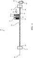
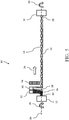
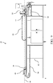
- Fig. 3 illustrates a non-limiting example of the apparatus 10 configured to manufacture a wire cable assembly that includes an insulated twisted wire pair 14 and an uninsulated drain wire 32 that is spirally wrapped by a conductive second tape 38 and an insulative or dielectric first tape 24.
- This type of wire cable is typically referred to as a shielded twisted pair.
- the wire pair 14 is secured in the first and second clamps 12, 16 and the second clamp 16 is rotated in the direction 20 while the first clamp 12 remains locked in the fixed position, thereby twisting the wires of the wire pair 14 one about the other.
- the apparatus 10 further includes a drain wire spool 34 that is attached to the transport mechanism, which is configured to move the drain wire spool 34 in a lateral direction 36 that is generally parallel to the axis 18 of the first and second clamps 12, 16.
- the second clamp 16 is designed to hold or secure the drain wire 32 in addition to the wire pair 14.
- the drain wire 32 is typically secured within the second clamp 16 after the wire pair 14 is twisted together.
- the transport mechanism then moves the drain wire spool 34 in the lateral direction 36 from the first location to the second location applying the drain wire 32 to the twisted wire pair 14.
- the second clamp 16 may be rotated in the direction 20 for a few revolutions while the drain wire spool 34 in moving to the second location 30 thereby wrapping the drain wire 32 about the twisted wire pair 14 and prevent sagging of the drain wire 32.
- the drain wire spool 34 reaches the second location 30, the drain wire 32 is cut from the drain wire spool 34 and the drain wire 32 is secured in the first clamp 12.
- the apparatus 10 also includes a second tape reel 40 that holds a second tape 38.
- the second tape reel 40 is preferably attached to the same transport mechanism (not shown in Figs. 1-5 ) as the first tape reel 22 so that they move in tandem with the first tape reel 22.
- the first and second tapes 24, 38 are attached to the wire pair 14 and as the wire pair 14 rotates and the first and second tape reels 22, 40 move from the second location 30 near the first clamp 12 to the first location 28 near the second clamp 16, thereby wrapping the first and second tape 24, 38 around the wire pair 14.
- the first tape 24 is a flexible insulative tape, such as a vinyl tape.
- the first tape 24 may or may not have an adhesive backing.
- the second tape 38 is a flexible conductive material, such as aluminized biaxially-orieneted polyethylene terephthalate (PET) film or tape.
- PET polyethylene terephthalate
- This tape is commonly known by the trade name MYLAR and the aluminized PET tape will hereafter be referred to as MYLAR tape.
- the first and second tape reels 22, 40 are arranged so that the conductive second tape 38 is applied in direct contact with the drain wire 32 and the insulative first tape 24 is applied over the second tape 38.
- the apparatus 10 includes a frame 42 on which the components are mounted.
- the first and second clamps 12, 16 are individually rotated by a pair of servo motors 44, 46 that are coupled to and controlled by an apparatus 10 controller (not shown).
- the controller determines the number of rotations, rotational direction 20 and speed of the pair of servo motors 44, 46 to produce the desired pitch of the twisted wire pair 14 and to synchronize the rotation of the first and second clamps 12, 16 to rotate the twisted wire pair 14.
- a third servo motor 52 is attached to the transport mechanism 50.
- the third servo motor 52 is also coupled to and controlled by the controller to synchronize the movement of the first and second tape reels 22, 40 while the twisted wire pair 14 is rotated in order to control the pitch and overlap of the tapes as they are applied to the twisted wire pair 14.
- the transport mechanism 50 is attached to a pair of guide rails 54 located generally parallel to the axis 18 of the first and second clamps 12, 16 that guide the transport mechanism 50 and thus the first and second tape reels 22, 40 along the axis 18 of the first and second clamps 12, 16.
- the first clamp 12 is mounted to a fixed location on the frame 42 while the second clamp 16 may be located at different locations along the frame 42 to accommodate wire harness assemblies of different length.
- the controller is housed within an enclosure attached to the frame 42.
- the apparatus 10 includes flexible cable trays 56 to carry the power and signal wires (not shown) to the second clamp servo motor 46 and transport mechanism servo motor 52.
- the apparatus 10 further includes an electrical continuity tester 58 which is configured to check the electrical continuity of the wire pair 14 and drain wire 32 after the first and second tapes 24, 38 are applied to the twisted wire pair 14.
- the tester may also check for short circuits between the wires of the twisted wire pair 14 to the drain wire 32.
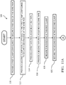
- Fig. 11 illustrates a method 100 of manufacturing a wire cable assembly including an insulated twisted wire pair 14 having an insulative first tape 24 spirally wrapped about said wire pair 14 and optionally including an uninsulated drain wire 32 and a conductive second tape 38 spirally wrapped about said wire pair 14.
- the apparatus 10 described supra may be manufactured according to this method 100.
- step 110 PROVIDE A FIRST CLAMP CONFIGURED TO SECURE A FIRST END OF THE WIRE PAIR, a first clamp, such as the first clamp 12 described supra is provided.
- a second clamp such as the second clamp 16 described supra is provided axially opposed to the first clamp 12.
- a first tape reel such as the first tape reel 22 described supra is provided.
- the first tape may be a flexible insulative tape, such as the first tape 24 described supra.
- a second tape reel such as the second tape reel 40 described supra is provided.
- the second tape may be a flexible conductive tape, such as the second tape 38 described supra.
- step 118 SECURE THE FIRST END IN THE FIRST CLAMP, one end of the wire pair 14 is secured in the first clamp 12.
- step 120 SECURE THE SECOND END IN THE SECOND CLAMP, the other end of the wire pair 14 is secured in the second clamp 16.
- step 122 ROTATE THE SECOND CLAMP WHILE FIXING THE POSITION OF THE FIRST CLAMP, the second clamp 16 is rotated in the direction 20 while holding the position of the first clamp 12 so that it will not rotate thereby twisting the wires of the wire pair 14 one about the other.
- the second clamp 16 may be rotated in the direction 60 opposite to the direction 20 in which the wire pair 14 was twisted in order to relieve strain in the twisted wire pair 14 caused by the twisting.
- the second clamp 16 is preferably rotated less than two revolutions in the opposite direction 60 in this step 124.
- an uninsulated drain wire 32 is secured within the first and second clamps 12, 16 in addition to the now twisted wire pair 14.
- the drain wire 32 may be secured in the second clamp 16 and applied to the wire pair 14 from a drain wire spool 34 attached to the transport mechanism 50 as the transport mechanism 50 moves in a lateral direction 36 from a first position near the second clamp 16 to a second position near the first clamp 12.
- the drain wire 32 is then cut from the drain wire spool 34 and the cut end is inserted in the first clamp 12.
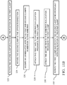
- step 1208 ATTACH THE FIRST TAPE TO THE WIRE PAIR IN A LOCATION PROXIMATE THE FIRST CLAMP, an end of the first tape 24 is attached to the wires of the wire pair 14 in a first location 28 near the first clamp 12.
- the first tape 24 may be attached to the wire pair 14 by an adhesive tape or tie wrap.
- step 130 ATTACH THE SECOND TAPE TO THE WIRE PAIR IN A LOCATION PROXIMATE THE FIRST CLAMP, an end of the second tape 38 is attached to the wires of the wire pair 14 near the first clamp 12.
- the second tape 34 may be attached to the wire pair 14 by an adhesive tape or tie wrap.
- step 132 ROTATE THE FIRST CLAMP AND ROTATE THE SECOND CLAMP SYNCHRONOUSLY WITH THE ROTATION OF THE FIRST CLAMP, the first clamp 12 is rotated in synchronization with the second clamp 16, thereby rotating the wire pair 14 and the drain wire 32 without further twisting the wire pair 14 or the drain wire 32.
- step 134 MOVE THE FIRST TAPE REEL GENERALLY PARALLEL TO THE AXIS OF THE FIRST AND SECOND CLAMPS AS THEY ROTATE SYNCHRONOUSLY, coincidental with step 130, the first tape reel 22 is moved in a lateral direction 26 generally parallel to the axis 18 of the first and second clamps 12, 16, thereby spirally wrapping the first tape 24 about the twisted wire pair 14.
- the first tape reel 22 is moved from a location near one of the clamps to a location near the other clamp.
- the speed at which the first and second clamp 12, 16 rotate and the speed at which the first tape reel 22 moves parallel to the axis 18 determines the pitch or overlap of the first tape 24 as it is wrapped.
- step 136 MOVE THE SECOND TAPE REEL IN TANDEM WITH THE FIRST TAPE REEL, the second tape reel 40 is moved in tandem with the first tape reel 22 thereby spirally wrapping the second tape 38 about the twisted wire pair 14.
- step 138 CUT THE FIRST AND SECOND TAPE, after the first and second tapes 24, 38 are wrapped about the twisted wire pair 14, the first and second tapes 24, 38 are cut from the first and second tape reels 22, 40.
- step 140 SECURE THE CUT ENDS OF THE FIRST AND SECOND TAPE TO THE WIRE PAIR, the cut ends of the first and second tape 24, 34 are secured to the wire pair 14, e.g. by use of a tie wrap, adhesive tape, or hot melt glue.
- step 142 CHECK ELECTRICAL CONTINUITY OF THE WIRE PAIR AND UNINSTALLED WIRE, the wire pair 14 and the drain wire 32 are tested for electrical continuity and short circuits between the wires.
- a single apparatus 10 configured to manufacture a wire cable assembly including an insulated twisted wire pair 14 having a tape spirally wrapped about said wire pair 14 and a method 100 of manufacturing a wire cable assembly including an insulated twisted wire pair 14 having a tape spirally wrapped about said wire pair 14 using the apparatus 10 is provided.
- the apparatus 10 may be further configured to manufacture a twisted pair wire cable assembly that includes an uninsulated drain wire 32 and has a conductive tape and an insulative tape spirally wrapped about said wire pair 14.
- the apparatus 10 provides the benefits of producing the wire cable assemblies on a single machine, thus eliminating in-process inventory required by manufacturing the wire assemblies on multiple machines as described in the Background of the Invention. This reduces the cost of in-process inventory and eliminates damage caused by handling between two or more machines.
- the apparatus 10 does not include feed wheels, so damage to the wire cable assemblies caused by pressure of feed wheels is also eliminated. Also, the apparatus 10 does not require the drain wire 32 to be pulled through the tape wrapping machine as described in the Background of the Invention. This eliminates the possibility of the drain wire 32 tangling with the twisted wire pair 14 and damaging the insulation of the twisted wire pair 14.
- first, second, etc. does not denote any order of importance, but rather the terms first, second, etc. are used to distinguish one element from another.
- use of the terms a, an, etc. do not denote a limitation of quantity, but rather denote the presence of at least one of the referenced items.
Claims (15)
- Vorrichtung (10), die konfiguriert ist zum Herstellen einer Drahtkabelanordnung mit einem isolierten verdrillten Drahtpaar (14) mit einem spiralförmig um das Drahtpaar (14) gewickelten Band (24), wobei die Vorrichtung (10) aufweist:eine erste Klemme (12) zum Befestigen eines ersten Endes des Drahtpaares (14) und zum Rotieren oder Beibehalten einer festen Position;eine zweite Klemme (16) zum Befestigen eines zweiten Endes des Drahtpaares (14) axial entgegengesetzt zu der ersten Klemme (12), wobei die zweite Klemme (16) konfiguriert ist, zu rotieren, während die erste Klemme (12) die feste Position beibehält, wodurch die Drähte des Drahtpaares (14) umeinander verdrillt werden, und die zweite Klemme konfiguriert ist, synchron mit der Rotation der ersten Klemme (12) zu rotieren, wodurch das Drahtpaar (14) ohne Verdrillen rotiert wird; undeine erste Bandspule (22), die ein erstes Band (24) hält und konfiguriert ist, sich im Allgemeinen parallel zu der Achse (18) der ersten und zweiten Klemmen (12, 16) zu bewegen, wenn diese synchron rotieren, wodurch das erste Band (24) um das Drahtpaar (14) gewickelt wird.
- Vorrichtung (10) gemäß Anspruch 1, die weiter eine zweite Bandspule (40) aufweist, die ein zweites Band (34) hält und konfiguriert ist, sich zusammen mit der ersten Bandspule (22) zu bewegen, wodurch das zweite Band (34) um das Drahtpaar (14) gewickelt wird.
- Vorrichtung (10) gemäß Anspruch 2, wobei das erste Band (24) ein elektrisch leitfähiges Band ist und das zweite Band (34) ein dielektrisches Band ist.
- Vorrichtung (10) gemäß einem der Ansprüche 1 bis 3, dadurch gekennzeichnet, dass die zweite Klemme (16) weiter konfiguriert ist, eine feste Position beizubehalten, und die erste Klemme (12) weiter konfiguriert ist, zu rotieren, während die zweite Klemme (16) die feste Position beibehält, wodurch die Drähte des Drahtpaares (14) umeinander verdrillt werden.
- Vorrichtung (10) gemäß einem der Ansprüche 1 bis 4, die weiter aufweist:einen ersten Servomotor (44), der mechanisch mit der ersten Klemme (12) gekoppelt ist und konfiguriert ist zum Rotieren der ersten Klemme (12); undeinen zweiten Servomotor (46), der mechanisch mit der zweiten Klemme (16) gekoppelt ist und konfiguriert ist zum Rotieren der zweiten Klemme (16).
- Vorrichtung (10) gemäß einem der Ansprüche 1 bis 5, die weiter aufweist:
einen dritten Servomotor (52), der mechanisch mit der ersten Bandspule (22) gekoppelt ist und konfiguriert ist, um die erste Bandspule (22) in eine Richtung (26) im Allgemeinen parallel zu der Achse (18) der ersten und zweiten Klemmen (12, 16) zu bewegen. - Vorrichtung (10) gemäß einem der Ansprüche 1 bis 6, wobei die ersten und zweiten Klemmen (12, 16) weiter konfiguriert sind zum Befestigen eines nicht-isolierten Beidrahts (32) zusätzlich zu dem Drahtpaar (14).
- Vorrichtung (10) gemäß Anspruch 7, dadurch gekennzeichnet, dass die Vorrichtung weiter einen elektrischen Durchgangsprüfer (58) aufweist, der konfiguriert ist zum Prüfen eines elektrischen Durchgangs des Drahtpaares (14) und des Beidrahts (32) nach dem Aufbringen des ersten Bands (24).
- Verfahren (100) zum Herstellen einer Drahtkabelanordnung mit einem isolierten verdrillten Drahtpaar (14) mit einem spiralförmig um das Drahtpaar (14) gewickelten Band (24), wobei das Verfahren (100) aufweist:Vorsehen (110) einer ersten Klemme (12), die konfiguriert ist zum Befestigen eines ersten Endes des Drahtpaares (14);Vorsehen (112) einer zweiten Klemme (16) axial entgegengesetzt zu der ersten Klemme (12), die konfiguriert ist zum Befestigen eines zweiten Endes des Drahtpaares (14);Vorsehen (114) einer ersten Bandspule (22), die ein erstes Band (24) hält;Befestigen (118) des ersten Endes in der ersten Klemme (12);Befestigen (120) des zweiten Endes in der zweiten Klemme (16);Anbringen (128) eines Endes des ersten Bandes (24) an dem Drahtpaar (14) an einer Stelle nahe der ersten Klemme (12);Rotieren (122) der zweiten Klemme (16), während die Position der ersten Klemme (12) gehalten wird, wodurch die Drähte des Drahtpaares (14) umeinander verdrillt werden und das Ende des ersten Bandes (24) innerhalb des Drahtpaares (14) befestigt wird;Rotieren (132) der ersten Klemme (12);Rotieren (132) der zweiten Klemme (16) synchron mit der Rotation der ersten Klemme (12), wodurch das Drahtpaar (14) ohne Verdrillen rotiert wird; undBewegen (134) der ersten Bandspule (22) in eine Richtung (26) im Allgemeinen parallel zu der Achse (18) der ersten und zweiten Klemmen (12, 16), wenn sie synchron rotieren, wodurch das erste Band (24) um das Drahtpaar (14) gewickelt wird.
- Verfahren (100) gemäß Anspruch 9, das weiter aufweist:Vorsehen (116) einer zweiten Bandspule (40), die ein zweites Band (34) hält;Anbringen (130) eines Endes des zweiten Bandes (34) an dem Drahtpaar (14) an der Stelle nahe der ersten Klemme (12);Rotieren (122) der zweiten Klemme (16), während die Position der ersten Klemme (12) gehalten wird, wodurch das Ende des zweiten Bandes (34) innerhalb des Drahtpaares (14) befestigt wird; undBewegen (136) der zweiten Bandspule (40) zusammen mit der ersten Bandspule (22) von einer Stelle nahe der ersten Klemme (12) zu einer Stelle nahe der zweiten Klemme (16), wodurch das zweite Band (34) um das Drahtpaar (14) gewickelt wird.
- Verfahren (100) gemäß Anspruch 10, das weiter die Schritte aufweist:Schneiden (138) des ersten und zweiten Bandes (24, 34) nach dem Schritt (136) des Bewegens der zweiten Bandspule (40) zusammen mit der ersten Bandspule (22); undBefestigen (140) der Schnittenden des ersten und zweiten Bandes (24, 34) an dem Drahtpaar (14).
- Verfahren (100) gemäß Anspruch 10, wobei das erste Band (24) ein elektrisch leitfähiges Band ist und das zweite Band (34) ein dielektrisches Band ist.
- Verfahren (100) gemäß einem der Ansprüche 9 bis 12, das weiter den Schritt aufweist:
Befestigen (126) eines nicht-isolierten Beidrahts (32) in den ersten und zweiten Klemmen (12, 16) zusätzlich zu dem Drahtpaar (14) nach dem Schritt (122) des Rotierens der zweiten Klemme (16), während die Position der ersten Klemme (12) gehalten wird. - Verfahren (100) gemäß Anspruch 13, das weiter aufweist:
Prüfen (142) des elektrischen Durchgangs des Drahtpaares (14) und des Beidrahts (32) nach dem Schritt (134) des Bewegens der ersten Bandspule (22) in eine Richtung (26) im Allgemeinen parallel zu der Achse (18) der ersten und zweiten Klemmen (12, 16). - Verfahren (100) gemäß einem der Ansprüche 9 bis 14, das weiter aufweist:Rotieren (124) der zweiten Klemme (16) in die entgegengesetzte Richtung (60),wodurch eine Drahtbeanspruchung in dem Drahtpaar (14) entlastet wird, nach dem Schritt (122) des Rotierens der zweiten Klemme (16), während die Position der ersten Klemme (12) gehalten wird.
Applications Claiming Priority (1)
| Application Number | Priority Date | Filing Date | Title |
|---|---|---|---|
| US13/905,553 US9117573B2 (en) | 2013-05-30 | 2013-05-30 | Integrated wire cable twisting, wrapping, and testing apparatus and method of operating same |
Publications (3)
| Publication Number | Publication Date |
|---|---|
| EP2808875A1 EP2808875A1 (de) | 2014-12-03 |
| EP2808875B1 true EP2808875B1 (de) | 2018-10-31 |
| EP2808875B8 EP2808875B8 (de) | 2019-01-09 |
Family
ID=50771430
Family Applications (1)
| Application Number | Title | Priority Date | Filing Date |
|---|---|---|---|
| EP14169294.7A Active EP2808875B8 (de) | 2013-05-30 | 2014-05-21 | Integrierte Kabelverdrillungs-, Kabelumhüllungs- und Kabeltestvorrichtung und Betriebsverfahren dafür |
Country Status (3)
| Country | Link |
|---|---|
| US (1) | US9117573B2 (de) |
| EP (1) | EP2808875B8 (de) |
| CN (1) | CN104217815B (de) |
Families Citing this family (16)
| Publication number | Priority date | Publication date | Assignee | Title |
|---|---|---|---|---|
| CN104025209B (zh) * | 2011-11-11 | 2017-05-10 | 施洛伊尼格控股有限公司 | 扭绞装置和用于在扭绞装置中扭绞电导线或光导线的方法 |
| SG11201402171PA (en) | 2011-11-11 | 2014-08-28 | Schleuniger Holding Ag | Cable-gathering device (wire stacker) |
| EP2801984B1 (de) | 2013-05-08 | 2018-11-14 | Schleuniger Holding AG | Greifer, Verdrillkopf und Verdrillvorrichtung |
| CN105788763B (zh) * | 2016-04-08 | 2017-12-05 | 广东奥美格传导科技股份有限公司 | 绞线检测机 |
| US10315590B2 (en) | 2016-06-14 | 2019-06-11 | Hitachi Metals, Ltd. | Cable and wire harness |
| DE102016214483A1 (de) * | 2016-08-04 | 2018-02-08 | Leoni Kabel Gmbh | Datenleitung und Verfahren zur Herstellung einer Datenleitung |
| EP3349222A1 (de) * | 2017-01-13 | 2018-07-18 | Schleuniger Holding AG | Greifbacke und leitungsgreifer für ein paar von elektrischen oder optischen leitungen |
| JP6475765B2 (ja) * | 2017-01-17 | 2019-02-27 | 矢崎総業株式会社 | ツイスト線製造装置、及びツイスト線製造方法 |
| DE102017109819B4 (de) * | 2017-05-08 | 2018-12-20 | Lisa Dräxlmaier GmbH | Umwickeln eines Leitungssatzes mit Band |
| NL2019256B1 (nl) * | 2017-07-17 | 2019-01-30 | Havatec B V | Werkwijze en inrichting voor het torderen van een bundel plantenstelen in een boeket |
| AU2019330648A1 (en) * | 2018-08-21 | 2021-04-15 | Richard V. Campbell | Termination installation method for long cables |
| CN113439312A (zh) * | 2019-04-09 | 2021-09-24 | 利萨·德雷克塞迈尔有限责任公司 | 用于包绕电的导线组的装置 |
| CN112216445A (zh) * | 2019-07-12 | 2021-01-12 | 库迈思控股股份公司 | 半自动电缆加捻装置和转移方法 |
| US11309105B2 (en) | 2019-07-18 | 2022-04-19 | Aptiv Technologies Limited | Apparatus for center twisting wires |
| US10946434B2 (en) | 2019-07-18 | 2021-03-16 | Aptiv Technologies Limited | Apparatus and method for center twisting wires |
| JP2022053694A (ja) * | 2020-09-25 | 2022-04-06 | 日立金属株式会社 | 複合ケーブル及び複合ハーネス |
Family Cites Families (19)
| Publication number | Priority date | Publication date | Assignee | Title |
|---|---|---|---|---|
| US3616531A (en) * | 1969-10-21 | 1971-11-02 | Lindberg John E | Method for making a double helix type of supported fire detector sensor |
| US3847190A (en) * | 1972-12-19 | 1974-11-12 | Phillips Cable Ltd | Method and apparatus for twisting wires |
| US3957092A (en) * | 1974-04-22 | 1976-05-18 | Gardner-Denver Company | Apparatus for forming twisted pairs of conductor wire |
| DE3211428A1 (de) | 1982-01-22 | 1983-10-13 | Schmitz & Bierther GmbH & Co KG, 5200 Siegburg | Aus einem profilband aus polymeren oder elastromeren hergestellter schlauch fuer griffummantelungen |
| DE3211481C2 (de) * | 1982-03-29 | 1985-05-02 | Franz Kirsten Elektrotechnische Spezialfabrik, 6530 Bingen | Vorrichtung und Verfahren zur Umwicklung von länglichen Gegenständen, insbesondere von Kabeln |
| US5564268A (en) | 1994-04-08 | 1996-10-15 | Ceeco Machinery Manufacturing Ltd. | Apparatus and method for the manufacture of uniform impedance communication cables for high frequency use |
| EP0844704A3 (de) * | 1996-11-20 | 1999-08-11 | Baumann GmbH | Verfahren zum Herstellen von verdrillten, konfektionierten leitungen sowie Vorrichtung zum Durchführen des Verfahrens |
| JP3409643B2 (ja) * | 1997-06-05 | 2003-05-26 | 住友電装株式会社 | ツイスト電線製造装置 |
| DE29721664U1 (de) * | 1997-12-08 | 1998-05-14 | Wika Alexander Wiegand Gmbh | Differenzdruckmanometer |
| JP2000149684A (ja) * | 1998-11-16 | 2000-05-30 | Sumitomo Wiring Syst Ltd | ツイスト電線の加工装置 |
| US6289944B1 (en) | 1999-02-23 | 2001-09-18 | Komax Holding Ag | Method and equipment for the treatment and twisting together of a conductor pair |
| DE10107670B4 (de) * | 2001-02-19 | 2005-11-10 | Gluth Systemtechnik Gmbh | Verfahren und Vorrichtung zum Verdrillen von mindestens zwei Einzelleitungen |
| CN2643454Y (zh) * | 2003-07-10 | 2004-09-22 | 北京云电英纳超导电缆有限公司 | 超导电缆带材绕制装置 |
| JP2005071753A (ja) * | 2003-08-22 | 2005-03-17 | Sumitomo Wiring Syst Ltd | ツイストケーブル製造装置 |
| DE202009004913U1 (de) * | 2009-06-12 | 2010-07-22 | Pro.Eff Gmbh | Vorrichtung zum Verdrillen von Leitungen |
| CN102117685A (zh) * | 2009-12-31 | 2011-07-06 | 鞍钢钢绳有限责任公司 | 一种在线缆外缠绕钢丝的生产方法 |
| JP5619505B2 (ja) * | 2010-07-26 | 2014-11-05 | 矢崎総業株式会社 | ツイスト線の製造装置及び製造方法 |
| CN104025209B (zh) | 2011-11-11 | 2017-05-10 | 施洛伊尼格控股有限公司 | 扭绞装置和用于在扭绞装置中扭绞电导线或光导线的方法 |
| CN202480368U (zh) * | 2012-03-21 | 2012-10-10 | 深圳市得润电子股份有限公司 | 一种线材的胶带缠绕装置 |
-
2013
- 2013-05-30 US US13/905,553 patent/US9117573B2/en active Active
-
2014
- 2014-05-21 EP EP14169294.7A patent/EP2808875B8/de active Active
- 2014-05-29 CN CN201410235133.7A patent/CN104217815B/zh active Active
Non-Patent Citations (1)
| Title |
|---|
| None * |
Also Published As
| Publication number | Publication date |
|---|---|
| EP2808875A1 (de) | 2014-12-03 |
| US20140352867A1 (en) | 2014-12-04 |
| CN104217815A (zh) | 2014-12-17 |
| US9117573B2 (en) | 2015-08-25 |
| CN104217815B (zh) | 2017-04-12 |
| EP2808875B8 (de) | 2019-01-09 |
Similar Documents
| Publication | Publication Date | Title |
|---|---|---|
| EP2808875B1 (de) | Integrierte Kabelverdrillungs-, Kabelumhüllungs- und Kabeltestvorrichtung und Betriebsverfahren dafür | |
| US10020096B2 (en) | Shielded wire harness and method for manufacturing the same | |
| CN110800072B (zh) | 利用条带来缠绕线束 | |
| US20130283612A1 (en) | Terminal treatment method and terminal treatment apparatus for coaxial cable | |
| US20060179908A1 (en) | Method and device for processing a wire | |
| AU2016332198B2 (en) | High temperature superconductor wire bundling system and method | |
| JPS62184716A (ja) | 可撓性電線の製造方法 | |
| CN110034480B (zh) | 处理多根导线的装置及方法 | |
| JP6496478B2 (ja) | シールド電線及びシールド電線の製造方法 | |
| JPH01209604A (ja) | シールド電線およびその製造方法 | |
| US3138915A (en) | Method of forming a sectorconductor cable | |
| JP2012128977A (ja) | 撚り合わせケーブル製造装置およびケーブル連接体 | |
| JP2016062863A (ja) | ケーブルおよびケーブルの製造方法 | |
| JP2017162701A (ja) | ワイヤハーネス製造方法及び製造装置 | |
| JP2003032825A (ja) | 電線の皮剥ぎ方法と皮剥ぎ装置 | |
| CN217562306U (zh) | 一种电缆包纸机 | |
| JPH1131426A (ja) | ワイヤーハーネスの形成方法 | |
| EP0148850B1 (de) | Verfahren zur herstellung einer verpackung für elektrische heizkabel | |
| JP2003242846A (ja) | 通信ケーブル、通信ケーブルの製造方法、通信ケーブル用の撚り合わせ装置及び撚り合わせ方法 | |
| JPH0458126B2 (de) | ||
| JPH065121A (ja) | シールド付ワイヤハーネスとその製造方法 | |
| US230653A (en) | Island | |
| JPH04262313A (ja) | 横巻シールド線の巻付方法 | |
| JPH0935555A (ja) | 可撓性の電気ケーブル用の心線を造るための方法およびこの方法により造った心線 | |
| JPH0479106A (ja) | 長尺ケーブルの送出しおよび巻取り方法 |
Legal Events
| Date | Code | Title | Description |
|---|---|---|---|
| PUAI | Public reference made under article 153(3) epc to a published international application that has entered the european phase |
Free format text: ORIGINAL CODE: 0009012 |
|
| 17P | Request for examination filed |
Effective date: 20140521 |
|
| AK | Designated contracting states |
Kind code of ref document: A1 Designated state(s): AL AT BE BG CH CY CZ DE DK EE ES FI FR GB GR HR HU IE IS IT LI LT LU LV MC MK MT NL NO PL PT RO RS SE SI SK SM TR |
|
| AX | Request for extension of the european patent |
Extension state: BA ME |
|
| R17P | Request for examination filed (corrected) |
Effective date: 20150603 |
|
| RBV | Designated contracting states (corrected) |
Designated state(s): AL AT BE BG CH CY CZ DE DK EE ES FI FR GB GR HR HU IE IS IT LI LT LU LV MC MK MT NL NO PL PT RO RS SE SI SK SM TR |
|
| GRAP | Despatch of communication of intention to grant a patent |
Free format text: ORIGINAL CODE: EPIDOSNIGR1 |
|
| STAA | Information on the status of an ep patent application or granted ep patent |
Free format text: STATUS: GRANT OF PATENT IS INTENDED |
|
| INTG | Intention to grant announced |
Effective date: 20180529 |
|
| GRAS | Grant fee paid |
Free format text: ORIGINAL CODE: EPIDOSNIGR3 |
|
| GRAA | (expected) grant |
Free format text: ORIGINAL CODE: 0009210 |
|
| STAA | Information on the status of an ep patent application or granted ep patent |
Free format text: STATUS: THE PATENT HAS BEEN GRANTED |
|
| AK | Designated contracting states |
Kind code of ref document: B1 Designated state(s): AL AT BE BG CH CY CZ DE DK EE ES FI FR GB GR HR HU IE IS IT LI LT LU LV MC MK MT NL NO PL PT RO RS SE SI SK SM TR |
|
| REG | Reference to a national code |
Ref country code: CH Ref legal event code: EP Ref country code: GB Ref legal event code: FG4D |
|
| REG | Reference to a national code |
Ref country code: AT Ref legal event code: REF Ref document number: 1060375 Country of ref document: AT Kind code of ref document: T Effective date: 20181115 |
|
| REG | Reference to a national code |
Ref country code: DE Ref legal event code: R096 Ref document number: 602014034971 Country of ref document: DE |
|
| REG | Reference to a national code |
Ref country code: IE Ref legal event code: FG4D |
|
| REG | Reference to a national code |
Ref country code: DE Ref legal event code: R081 Ref document number: 602014034971 Country of ref document: DE Owner name: APTIV TECHNOLOGIES LIMITED, BB Free format text: FORMER OWNER: DELPHI TECHNOLOGIES, INC., TROY, MICH., US |
|
| REG | Reference to a national code |
Ref country code: CH Ref legal event code: PK Free format text: BERICHTIGUNG B8 |
|
| RAP2 | Party data changed (patent owner data changed or rights of a patent transferred) |
Owner name: APTIV TECHNOLOGIES LIMITED |
|
| REG | Reference to a national code |
Ref country code: NL Ref legal event code: MP Effective date: 20181031 |
|
| REG | Reference to a national code |
Ref country code: LT Ref legal event code: MG4D |
|
| REG | Reference to a national code |
Ref country code: AT Ref legal event code: MK05 Ref document number: 1060375 Country of ref document: AT Kind code of ref document: T Effective date: 20181031 |
|
| PG25 | Lapsed in a contracting state [announced via postgrant information from national office to epo] |
Ref country code: LV Free format text: LAPSE BECAUSE OF FAILURE TO SUBMIT A TRANSLATION OF THE DESCRIPTION OR TO PAY THE FEE WITHIN THE PRESCRIBED TIME-LIMIT Effective date: 20181031 Ref country code: ES Free format text: LAPSE BECAUSE OF FAILURE TO SUBMIT A TRANSLATION OF THE DESCRIPTION OR TO PAY THE FEE WITHIN THE PRESCRIBED TIME-LIMIT Effective date: 20181031 Ref country code: LT Free format text: LAPSE BECAUSE OF FAILURE TO SUBMIT A TRANSLATION OF THE DESCRIPTION OR TO PAY THE FEE WITHIN THE PRESCRIBED TIME-LIMIT Effective date: 20181031 Ref country code: BG Free format text: LAPSE BECAUSE OF FAILURE TO SUBMIT A TRANSLATION OF THE DESCRIPTION OR TO PAY THE FEE WITHIN THE PRESCRIBED TIME-LIMIT Effective date: 20190131 Ref country code: HR Free format text: LAPSE BECAUSE OF FAILURE TO SUBMIT A TRANSLATION OF THE DESCRIPTION OR TO PAY THE FEE WITHIN THE PRESCRIBED TIME-LIMIT Effective date: 20181031 Ref country code: PL Free format text: LAPSE BECAUSE OF FAILURE TO SUBMIT A TRANSLATION OF THE DESCRIPTION OR TO PAY THE FEE WITHIN THE PRESCRIBED TIME-LIMIT Effective date: 20181031 Ref country code: FI Free format text: LAPSE BECAUSE OF FAILURE TO SUBMIT A TRANSLATION OF THE DESCRIPTION OR TO PAY THE FEE WITHIN THE PRESCRIBED TIME-LIMIT Effective date: 20181031 Ref country code: NO Free format text: LAPSE BECAUSE OF FAILURE TO SUBMIT A TRANSLATION OF THE DESCRIPTION OR TO PAY THE FEE WITHIN THE PRESCRIBED TIME-LIMIT Effective date: 20190131 Ref country code: AT Free format text: LAPSE BECAUSE OF FAILURE TO SUBMIT A TRANSLATION OF THE DESCRIPTION OR TO PAY THE FEE WITHIN THE PRESCRIBED TIME-LIMIT Effective date: 20181031 Ref country code: IS Free format text: LAPSE BECAUSE OF FAILURE TO SUBMIT A TRANSLATION OF THE DESCRIPTION OR TO PAY THE FEE WITHIN THE PRESCRIBED TIME-LIMIT Effective date: 20190228 |
|
| PG25 | Lapsed in a contracting state [announced via postgrant information from national office to epo] |
Ref country code: PT Free format text: LAPSE BECAUSE OF FAILURE TO SUBMIT A TRANSLATION OF THE DESCRIPTION OR TO PAY THE FEE WITHIN THE PRESCRIBED TIME-LIMIT Effective date: 20190301 Ref country code: RS Free format text: LAPSE BECAUSE OF FAILURE TO SUBMIT A TRANSLATION OF THE DESCRIPTION OR TO PAY THE FEE WITHIN THE PRESCRIBED TIME-LIMIT Effective date: 20181031 Ref country code: GR Free format text: LAPSE BECAUSE OF FAILURE TO SUBMIT A TRANSLATION OF THE DESCRIPTION OR TO PAY THE FEE WITHIN THE PRESCRIBED TIME-LIMIT Effective date: 20190201 Ref country code: NL Free format text: LAPSE BECAUSE OF FAILURE TO SUBMIT A TRANSLATION OF THE DESCRIPTION OR TO PAY THE FEE WITHIN THE PRESCRIBED TIME-LIMIT Effective date: 20181031 Ref country code: SE Free format text: LAPSE BECAUSE OF FAILURE TO SUBMIT A TRANSLATION OF THE DESCRIPTION OR TO PAY THE FEE WITHIN THE PRESCRIBED TIME-LIMIT Effective date: 20181031 Ref country code: AL Free format text: LAPSE BECAUSE OF FAILURE TO SUBMIT A TRANSLATION OF THE DESCRIPTION OR TO PAY THE FEE WITHIN THE PRESCRIBED TIME-LIMIT Effective date: 20181031 |
|
| PG25 | Lapsed in a contracting state [announced via postgrant information from national office to epo] |
Ref country code: DK Free format text: LAPSE BECAUSE OF FAILURE TO SUBMIT A TRANSLATION OF THE DESCRIPTION OR TO PAY THE FEE WITHIN THE PRESCRIBED TIME-LIMIT Effective date: 20181031 Ref country code: IT Free format text: LAPSE BECAUSE OF FAILURE TO SUBMIT A TRANSLATION OF THE DESCRIPTION OR TO PAY THE FEE WITHIN THE PRESCRIBED TIME-LIMIT Effective date: 20181031 Ref country code: CZ Free format text: LAPSE BECAUSE OF FAILURE TO SUBMIT A TRANSLATION OF THE DESCRIPTION OR TO PAY THE FEE WITHIN THE PRESCRIBED TIME-LIMIT Effective date: 20181031 |
|
| REG | Reference to a national code |
Ref country code: DE Ref legal event code: R097 Ref document number: 602014034971 Country of ref document: DE |
|
| PG25 | Lapsed in a contracting state [announced via postgrant information from national office to epo] |
Ref country code: SK Free format text: LAPSE BECAUSE OF FAILURE TO SUBMIT A TRANSLATION OF THE DESCRIPTION OR TO PAY THE FEE WITHIN THE PRESCRIBED TIME-LIMIT Effective date: 20181031 Ref country code: RO Free format text: LAPSE BECAUSE OF FAILURE TO SUBMIT A TRANSLATION OF THE DESCRIPTION OR TO PAY THE FEE WITHIN THE PRESCRIBED TIME-LIMIT Effective date: 20181031 Ref country code: EE Free format text: LAPSE BECAUSE OF FAILURE TO SUBMIT A TRANSLATION OF THE DESCRIPTION OR TO PAY THE FEE WITHIN THE PRESCRIBED TIME-LIMIT Effective date: 20181031 Ref country code: SM Free format text: LAPSE BECAUSE OF FAILURE TO SUBMIT A TRANSLATION OF THE DESCRIPTION OR TO PAY THE FEE WITHIN THE PRESCRIBED TIME-LIMIT Effective date: 20181031 |
|
| PLBE | No opposition filed within time limit |
Free format text: ORIGINAL CODE: 0009261 |
|
| STAA | Information on the status of an ep patent application or granted ep patent |
Free format text: STATUS: NO OPPOSITION FILED WITHIN TIME LIMIT |
|
| 26N | No opposition filed |
Effective date: 20190801 |
|
| PG25 | Lapsed in a contracting state [announced via postgrant information from national office to epo] |
Ref country code: SI Free format text: LAPSE BECAUSE OF FAILURE TO SUBMIT A TRANSLATION OF THE DESCRIPTION OR TO PAY THE FEE WITHIN THE PRESCRIBED TIME-LIMIT Effective date: 20181031 |
|
| REG | Reference to a national code |
Ref country code: CH Ref legal event code: PL |
|
| PG25 | Lapsed in a contracting state [announced via postgrant information from national office to epo] |
Ref country code: CH Free format text: LAPSE BECAUSE OF NON-PAYMENT OF DUE FEES Effective date: 20190531 Ref country code: MC Free format text: LAPSE BECAUSE OF FAILURE TO SUBMIT A TRANSLATION OF THE DESCRIPTION OR TO PAY THE FEE WITHIN THE PRESCRIBED TIME-LIMIT Effective date: 20181031 Ref country code: LI Free format text: LAPSE BECAUSE OF NON-PAYMENT OF DUE FEES Effective date: 20190531 |
|
| REG | Reference to a national code |
Ref country code: BE Ref legal event code: MM Effective date: 20190531 |
|
| PG25 | Lapsed in a contracting state [announced via postgrant information from national office to epo] |
Ref country code: LU Free format text: LAPSE BECAUSE OF NON-PAYMENT OF DUE FEES Effective date: 20190521 |
|
| PG25 | Lapsed in a contracting state [announced via postgrant information from national office to epo] |
Ref country code: TR Free format text: LAPSE BECAUSE OF FAILURE TO SUBMIT A TRANSLATION OF THE DESCRIPTION OR TO PAY THE FEE WITHIN THE PRESCRIBED TIME-LIMIT Effective date: 20181031 |
|
| PG25 | Lapsed in a contracting state [announced via postgrant information from national office to epo] |
Ref country code: IE Free format text: LAPSE BECAUSE OF NON-PAYMENT OF DUE FEES Effective date: 20190521 |
|
| PG25 | Lapsed in a contracting state [announced via postgrant information from national office to epo] |
Ref country code: BE Free format text: LAPSE BECAUSE OF NON-PAYMENT OF DUE FEES Effective date: 20190531 |
|
| PG25 | Lapsed in a contracting state [announced via postgrant information from national office to epo] |
Ref country code: CY Free format text: LAPSE BECAUSE OF FAILURE TO SUBMIT A TRANSLATION OF THE DESCRIPTION OR TO PAY THE FEE WITHIN THE PRESCRIBED TIME-LIMIT Effective date: 20181031 |
|
| PG25 | Lapsed in a contracting state [announced via postgrant information from national office to epo] |
Ref country code: MT Free format text: LAPSE BECAUSE OF FAILURE TO SUBMIT A TRANSLATION OF THE DESCRIPTION OR TO PAY THE FEE WITHIN THE PRESCRIBED TIME-LIMIT Effective date: 20181031 Ref country code: HU Free format text: LAPSE BECAUSE OF FAILURE TO SUBMIT A TRANSLATION OF THE DESCRIPTION OR TO PAY THE FEE WITHIN THE PRESCRIBED TIME-LIMIT; INVALID AB INITIO Effective date: 20140521 |
|
| PG25 | Lapsed in a contracting state [announced via postgrant information from national office to epo] |
Ref country code: MK Free format text: LAPSE BECAUSE OF FAILURE TO SUBMIT A TRANSLATION OF THE DESCRIPTION OR TO PAY THE FEE WITHIN THE PRESCRIBED TIME-LIMIT Effective date: 20181031 |
|
| P01 | Opt-out of the competence of the unified patent court (upc) registered |
Effective date: 20230425 |
|
| PGFP | Annual fee paid to national office [announced via postgrant information from national office to epo] |
Ref country code: FR Payment date: 20230525 Year of fee payment: 10 Ref country code: DE Payment date: 20230517 Year of fee payment: 10 |
|
| PGFP | Annual fee paid to national office [announced via postgrant information from national office to epo] |
Ref country code: GB Payment date: 20230522 Year of fee payment: 10 |