EP2808875B1 - Integrated wire cable twisting, wrapping, and testing apparatus and method of operating same - Google Patents
Integrated wire cable twisting, wrapping, and testing apparatus and method of operating same Download PDFInfo
- Publication number
- EP2808875B1 EP2808875B1 EP14169294.7A EP14169294A EP2808875B1 EP 2808875 B1 EP2808875 B1 EP 2808875B1 EP 14169294 A EP14169294 A EP 14169294A EP 2808875 B1 EP2808875 B1 EP 2808875B1
- Authority
- EP
- European Patent Office
- Prior art keywords
- clamp
- tape
- wire pair
- wire
- pair
- Prior art date
- Legal status (The legal status is an assumption and is not a legal conclusion. Google has not performed a legal analysis and makes no representation as to the accuracy of the status listed.)
- Active
Links
Images


Classifications
-
- H—ELECTRICITY
- H01—ELECTRIC ELEMENTS
- H01B—CABLES; CONDUCTORS; INSULATORS; SELECTION OF MATERIALS FOR THEIR CONDUCTIVE, INSULATING OR DIELECTRIC PROPERTIES
- H01B13/00—Apparatus or processes specially adapted for manufacturing conductors or cables
- H01B13/22—Sheathing; Armouring; Screening; Applying other protective layers
- H01B13/26—Sheathing; Armouring; Screening; Applying other protective layers by winding, braiding or longitudinal lapping
-
- H—ELECTRICITY
- H01—ELECTRIC ELEMENTS
- H01B—CABLES; CONDUCTORS; INSULATORS; SELECTION OF MATERIALS FOR THEIR CONDUCTIVE, INSULATING OR DIELECTRIC PROPERTIES
- H01B13/00—Apparatus or processes specially adapted for manufacturing conductors or cables
- H01B13/02—Stranding-up
-
- H—ELECTRICITY
- H01—ELECTRIC ELEMENTS
- H01B—CABLES; CONDUCTORS; INSULATORS; SELECTION OF MATERIALS FOR THEIR CONDUCTIVE, INSULATING OR DIELECTRIC PROPERTIES
- H01B13/00—Apparatus or processes specially adapted for manufacturing conductors or cables
- H01B13/06—Insulating conductors or cables
- H01B13/08—Insulating conductors or cables by winding
- H01B13/085—Apparatus having the supply reels in a fixed position, the conductor or cable rotating about its own axis
-
- H—ELECTRICITY
- H01—ELECTRIC ELEMENTS
- H01B—CABLES; CONDUCTORS; INSULATORS; SELECTION OF MATERIALS FOR THEIR CONDUCTIVE, INSULATING OR DIELECTRIC PROPERTIES
- H01B13/00—Apparatus or processes specially adapted for manufacturing conductors or cables
- H01B13/22—Sheathing; Armouring; Screening; Applying other protective layers
- H01B13/227—Pretreatment
Definitions
- the invention generally relates to electrical wire cable manufacturing machines, and more particularly relates to a machine configured to automatically twist and wrap a twisted pair cable.
- Twisted wire pair cables used in automotive wire harnesses may also include an uninsulated "drain" wire and are wrapped in a conductive tape or foil that provides an electromagnetic shield. The conductive tape is then overwrapped with an insulative tape.
- a post twister machine that twists two or more wires to have a specific pitch or number of twists per unit length, e.g. twists per meter.
- the twisted wire pair along with the drain wire are then run through a dual taper machine, so named because it applies both the conductive tape and insulative tape to the wires at the same time.
- the dual taper machine spirally wraps the wires with the conductive tape and insulative tape.
- the dual taper machine typically uses feed wheels to pull the wires through the machine as the tape is applied.
- the pressure of the feed wheels on the wire pair provides an opportunity to damage the twisted wire pair.
- the operator may be required to pull the twisted pair wires though the dual taper machine before the feed wheels are engaged, providing another opportunity for damage.
- the drain wire is typically fed into the dual taper machine from a spool. As the wires are pulled through the dual taper machine the drain wire can tangle and become wrapped around the wire pair in such a way as to pinch through the insulation of the wire pair, causing a product failure.
- Damage to the insulated twisted wire pair that occurs during the manufacturing process or prior to the manufacturing process can create a failure when the wiring harness is used in the vehicle. Therefore, a facility to electrically test the twisted pair to ensure manufacturing quality is desired.
- an apparatus configured to manufacture a wire cable assembly including an insulated twisted wire pair having a tape spirally wrapped about said wire pair according to claim 1 .
- the apparatus includes a first clamp to secure a first end of the wire pair.
- the first clamp is configured to rotate or maintain a fixed position.
- the apparatus also includes a second clamp to secure a second end of the wire pair.
- the second clamp axially opposed to the first clamp.
- the second clamp is also configured to rotate while the first clamp maintains the fixed position thereby twisting the wires of the wire pair one about the other or to rotate synchronously with the rotation of the first clamp thereby rotating the wire pair without further twisting wire pair.
- the second clamp may be configured to maintain a fixed position and the first clamp may be configured to rotate while the second clamp maintains the fixed position thereby twisting the wires of the wire pair one about the other.
- the first and second clamps may be further configured to secure an uninsulated drain wire in addition to the wire pair.
- the apparatus may include a first servo motor that is mechanically coupled to the first clamp and is configured to rotate the first clamp and a second servo motor that is mechanically coupled to the second clamp and is configured to rotate the second clamp.
- the apparatus further includes a first tape reel that holds a first tape.
- the first tape reel is configured to move generally parallel to the axis of the first and second clamps when they rotate synchronously thereby wrapping the first tape around the wire pair.
- the apparatus may also include a second tape reel that holds a second tape.
- the second tape reel is configured to move in tandem with the first tape reel, thereby also wrapping the second tape around the wire pair.
- the apparatus may include a third servo motor that is mechanically coupled to the first tape reel and is configured to move the first tape reel in the direction generally parallel to the axis of the first and second clamps.
- the apparatus may also include an electrical continuity tester configured to check electrical continuity of the wire pair and drain wire after the first tape is applied.
- a method of manufacturing a wire cable assembly including an insulated twisted wire pair having a tape spirally wrapped about said wire pair according to claim 9 includes the steps of providing a first clamp configured to secure a first end of the wire pair, providing a second clamp axially opposed to the first clamp configured to secure a second end of the wire pair, and providing a first tape reel holding a first tape.
- the method also includes the steps of securing the first end in the first clamp, securing the second end in the second clamp, and attaching an end of the first tape to the wire pair proximate the first clamp.
- the method further includes the steps of rotating the second clamp while fixing the position of the first clamp, thereby twisting the wires of the wire pair one about the other, securing the end of the first tape within the wire pair, rotating the first clamp, and rotating the second clamp synchronously with the rotation of the first clamp thereby rotating the wire pair without twisting.
- the method additionally includes the steps of moving the first tape reel in a direction generally parallel to the axis of the first and second clamps as they rotate synchronously thereby wrapping the first tape around the wire pair.
- the method may also include the steps of providing a second tape reel holding a second tape, attaching an end of the second tape to the wire pair in the location proximate the first clamp, rotating the second clamp while fixing the position of the first clamp, thereby securing the end of the second tape within the wire pair, and moving the second tape reel in tandem with the first tape reel from a location proximate the first clamp to a location proximate the second clamp thereby wrapping the second tape around the wire pair.
- the method may include the step of rotating the second clamp in the opposite direction thereby relieving wire stress in the wire pair and/or the step of securing an uninsulated drain wire in the first and second clamps in addition to the wire pair
- the method may further include the steps of cutting the first and second tape and securing the cut ends of the first and second tape to the wire pair.
- the method may include the step of checking electrical continuity of the wire pair.
- a single machine designed to manufacture a wire cable assembly that includes an insulated twisted wire pair having a tape spirally wrapped about the wire pair.
- the machine is also capable of manufacturing a wire cable assembly that additionally includes a non-insulated drain wire and is additionally wrapped with an electrically conductive foil or tape to provide an electromagnetic shield around the twisted wire pair.
- a method of manufacturing this wire cable using this machine is also presented herein.
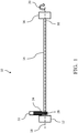
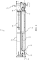
- Fig. 1 illustrates a non-limiting example of an integrated wire cable twisting, wrapping, and testing machine 10 or apparatus 10, hereafter the apparatus 10.
- the illustrations of Figs. 1-5 are schematic representations to simplify the explanation of the elements of the apparatus 10.
- Detailed illustrations of the apparatus 10 are found in Figs. 6- 10 .
- the apparatus 10 is designed to manufacture a wire cable assembly that includes an insulated twisted wire pair with a tape spirally wrapped about the wire pair. This type of wire cable is typically referred to as an unshielded twisted pair.
- the apparatus 10 includes a first wire chuck or first clamp 12 that is configured to hold or secure one end of a pair of insulated wires 14 and a second wire chuck or second clamp 16 configured to hold or secure the other end of the wire pair 14.
- the wire pair 14 is held substantially taut between the first and second clamps 12, 16.
- the first and second clamps 12, 16 may be designed to hold terminated wire ends, i.e. wire ends having terminals or contacts attached and/or the clamps may be designed to hold unterminated wire ends.
- the second clamp 16 is axially opposed to the first clamp 12.
- the first clamp 12 is constructed to be locked in a fixed position so that it does not rotate.
- the second clamp 16 is designed to rotate about the axis 18 between the first and second clamp 12, 16 the direction 20 while the first clamp 12 remains locked in the fixed position, thereby twisting the wires of the wire pair 14 one about the other.
- the number of rotations and the speed of rotation are controlled in order to provide the proper pitch or twists per unit length of the twisted wire pair 14.
- the first clamp 12 is also configured to rotate about the axis 18 between the first and second clamp 12, 16.
- the first clamp 12 is configured to rotate in the direction 20 synchronously with the rotation of the second clamp 16 thereby rotating the wire pair 14 without further twisting or untwisting the wire pair 14.
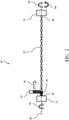
- the apparatus 10 also includes first tape reel 22 that holds a first tape 24.
- the first tape reel 22 is attached to a transport mechanism (not shown in Figs. 1-5 ) configured to move the first tape reel 22 in a lateral direction 26 that is generally parallel to the axis 18 of the first and second clamps 12, 16 when they rotate synchronously.
- the first tape 24 is attached to the wire pair 14 and as the wire pair 14 rotates, thereby enmeshing the end of the first tape 24 in the twists of the wire pair 14.
- the first tape reel 22 moves in the lateral direction 26 and the wire pair 14 is rotated by the first and second clamps 12, 16, the first tape 24 is wrapped around the wire pair 14.
- the first tape reel 22 moves from a first location 28 near the first clamp 12 to a second location 30 near the second clamp 16.
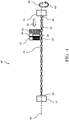
- Fig. 3 illustrates a non-limiting example of the apparatus 10 configured to manufacture a wire cable assembly that includes an insulated twisted wire pair 14 and an uninsulated drain wire 32 that is spirally wrapped by a conductive second tape 38 and an insulative or dielectric first tape 24.
- This type of wire cable is typically referred to as a shielded twisted pair.
- the wire pair 14 is secured in the first and second clamps 12, 16 and the second clamp 16 is rotated in the direction 20 while the first clamp 12 remains locked in the fixed position, thereby twisting the wires of the wire pair 14 one about the other.
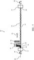
- the apparatus 10 further includes a drain wire spool 34 that is attached to the transport mechanism, which is configured to move the drain wire spool 34 in a lateral direction 36 that is generally parallel to the axis 18 of the first and second clamps 12, 16.
- the second clamp 16 is designed to hold or secure the drain wire 32 in addition to the wire pair 14.
- the drain wire 32 is typically secured within the second clamp 16 after the wire pair 14 is twisted together.
- the transport mechanism then moves the drain wire spool 34 in the lateral direction 36 from the first location to the second location applying the drain wire 32 to the twisted wire pair 14.
- the second clamp 16 may be rotated in the direction 20 for a few revolutions while the drain wire spool 34 in moving to the second location 30 thereby wrapping the drain wire 32 about the twisted wire pair 14 and prevent sagging of the drain wire 32.
- the drain wire spool 34 reaches the second location 30, the drain wire 32 is cut from the drain wire spool 34 and the drain wire 32 is secured in the first clamp 12.
- the apparatus 10 also includes a second tape reel 40 that holds a second tape 38.
- the second tape reel 40 is preferably attached to the same transport mechanism (not shown in Figs. 1-5 ) as the first tape reel 22 so that they move in tandem with the first tape reel 22.
- the first and second tapes 24, 38 are attached to the wire pair 14 and as the wire pair 14 rotates and the first and second tape reels 22, 40 move from the second location 30 near the first clamp 12 to the first location 28 near the second clamp 16, thereby wrapping the first and second tape 24, 38 around the wire pair 14.
- the first tape 24 is a flexible insulative tape, such as a vinyl tape.
- the first tape 24 may or may not have an adhesive backing.
- the second tape 38 is a flexible conductive material, such as aluminized biaxially-orieneted polyethylene terephthalate (PET) film or tape.
- PET polyethylene terephthalate
- This tape is commonly known by the trade name MYLAR and the aluminized PET tape will hereafter be referred to as MYLAR tape.
- the first and second tape reels 22, 40 are arranged so that the conductive second tape 38 is applied in direct contact with the drain wire 32 and the insulative first tape 24 is applied over the second tape 38.
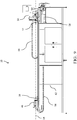
- the apparatus 10 includes a frame 42 on which the components are mounted.
- the first and second clamps 12, 16 are individually rotated by a pair of servo motors 44, 46 that are coupled to and controlled by an apparatus 10 controller (not shown).
- the controller determines the number of rotations, rotational direction 20 and speed of the pair of servo motors 44, 46 to produce the desired pitch of the twisted wire pair 14 and to synchronize the rotation of the first and second clamps 12, 16 to rotate the twisted wire pair 14.
- a third servo motor 52 is attached to the transport mechanism 50.
- the third servo motor 52 is also coupled to and controlled by the controller to synchronize the movement of the first and second tape reels 22, 40 while the twisted wire pair 14 is rotated in order to control the pitch and overlap of the tapes as they are applied to the twisted wire pair 14.
- the transport mechanism 50 is attached to a pair of guide rails 54 located generally parallel to the axis 18 of the first and second clamps 12, 16 that guide the transport mechanism 50 and thus the first and second tape reels 22, 40 along the axis 18 of the first and second clamps 12, 16.
- the first clamp 12 is mounted to a fixed location on the frame 42 while the second clamp 16 may be located at different locations along the frame 42 to accommodate wire harness assemblies of different length.
- the controller is housed within an enclosure attached to the frame 42.
- the apparatus 10 includes flexible cable trays 56 to carry the power and signal wires (not shown) to the second clamp servo motor 46 and transport mechanism servo motor 52.
- the apparatus 10 further includes an electrical continuity tester 58 which is configured to check the electrical continuity of the wire pair 14 and drain wire 32 after the first and second tapes 24, 38 are applied to the twisted wire pair 14.
- the tester may also check for short circuits between the wires of the twisted wire pair 14 to the drain wire 32.
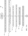
- Fig. 11 illustrates a method 100 of manufacturing a wire cable assembly including an insulated twisted wire pair 14 having an insulative first tape 24 spirally wrapped about said wire pair 14 and optionally including an uninsulated drain wire 32 and a conductive second tape 38 spirally wrapped about said wire pair 14.
- the apparatus 10 described supra may be manufactured according to this method 100.
- step 110 PROVIDE A FIRST CLAMP CONFIGURED TO SECURE A FIRST END OF THE WIRE PAIR, a first clamp, such as the first clamp 12 described supra is provided.
- a second clamp such as the second clamp 16 described supra is provided axially opposed to the first clamp 12.
- a first tape reel such as the first tape reel 22 described supra is provided.
- the first tape may be a flexible insulative tape, such as the first tape 24 described supra.
- a second tape reel such as the second tape reel 40 described supra is provided.
- the second tape may be a flexible conductive tape, such as the second tape 38 described supra.
- step 118 SECURE THE FIRST END IN THE FIRST CLAMP, one end of the wire pair 14 is secured in the first clamp 12.
- step 120 SECURE THE SECOND END IN THE SECOND CLAMP, the other end of the wire pair 14 is secured in the second clamp 16.
- step 122 ROTATE THE SECOND CLAMP WHILE FIXING THE POSITION OF THE FIRST CLAMP, the second clamp 16 is rotated in the direction 20 while holding the position of the first clamp 12 so that it will not rotate thereby twisting the wires of the wire pair 14 one about the other.
- the second clamp 16 may be rotated in the direction 60 opposite to the direction 20 in which the wire pair 14 was twisted in order to relieve strain in the twisted wire pair 14 caused by the twisting.
- the second clamp 16 is preferably rotated less than two revolutions in the opposite direction 60 in this step 124.
- an uninsulated drain wire 32 is secured within the first and second clamps 12, 16 in addition to the now twisted wire pair 14.
- the drain wire 32 may be secured in the second clamp 16 and applied to the wire pair 14 from a drain wire spool 34 attached to the transport mechanism 50 as the transport mechanism 50 moves in a lateral direction 36 from a first position near the second clamp 16 to a second position near the first clamp 12.
- the drain wire 32 is then cut from the drain wire spool 34 and the cut end is inserted in the first clamp 12.
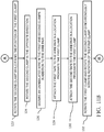
- step 1208 ATTACH THE FIRST TAPE TO THE WIRE PAIR IN A LOCATION PROXIMATE THE FIRST CLAMP, an end of the first tape 24 is attached to the wires of the wire pair 14 in a first location 28 near the first clamp 12.
- the first tape 24 may be attached to the wire pair 14 by an adhesive tape or tie wrap.
- step 130 ATTACH THE SECOND TAPE TO THE WIRE PAIR IN A LOCATION PROXIMATE THE FIRST CLAMP, an end of the second tape 38 is attached to the wires of the wire pair 14 near the first clamp 12.
- the second tape 34 may be attached to the wire pair 14 by an adhesive tape or tie wrap.
- step 132 ROTATE THE FIRST CLAMP AND ROTATE THE SECOND CLAMP SYNCHRONOUSLY WITH THE ROTATION OF THE FIRST CLAMP, the first clamp 12 is rotated in synchronization with the second clamp 16, thereby rotating the wire pair 14 and the drain wire 32 without further twisting the wire pair 14 or the drain wire 32.
- step 134 MOVE THE FIRST TAPE REEL GENERALLY PARALLEL TO THE AXIS OF THE FIRST AND SECOND CLAMPS AS THEY ROTATE SYNCHRONOUSLY, coincidental with step 130, the first tape reel 22 is moved in a lateral direction 26 generally parallel to the axis 18 of the first and second clamps 12, 16, thereby spirally wrapping the first tape 24 about the twisted wire pair 14.
- the first tape reel 22 is moved from a location near one of the clamps to a location near the other clamp.
- the speed at which the first and second clamp 12, 16 rotate and the speed at which the first tape reel 22 moves parallel to the axis 18 determines the pitch or overlap of the first tape 24 as it is wrapped.
- step 136 MOVE THE SECOND TAPE REEL IN TANDEM WITH THE FIRST TAPE REEL, the second tape reel 40 is moved in tandem with the first tape reel 22 thereby spirally wrapping the second tape 38 about the twisted wire pair 14.
- step 138 CUT THE FIRST AND SECOND TAPE, after the first and second tapes 24, 38 are wrapped about the twisted wire pair 14, the first and second tapes 24, 38 are cut from the first and second tape reels 22, 40.
- step 140 SECURE THE CUT ENDS OF THE FIRST AND SECOND TAPE TO THE WIRE PAIR, the cut ends of the first and second tape 24, 34 are secured to the wire pair 14, e.g. by use of a tie wrap, adhesive tape, or hot melt glue.
- step 142 CHECK ELECTRICAL CONTINUITY OF THE WIRE PAIR AND UNINSTALLED WIRE, the wire pair 14 and the drain wire 32 are tested for electrical continuity and short circuits between the wires.
- a single apparatus 10 configured to manufacture a wire cable assembly including an insulated twisted wire pair 14 having a tape spirally wrapped about said wire pair 14 and a method 100 of manufacturing a wire cable assembly including an insulated twisted wire pair 14 having a tape spirally wrapped about said wire pair 14 using the apparatus 10 is provided.
- the apparatus 10 may be further configured to manufacture a twisted pair wire cable assembly that includes an uninsulated drain wire 32 and has a conductive tape and an insulative tape spirally wrapped about said wire pair 14.
- the apparatus 10 provides the benefits of producing the wire cable assemblies on a single machine, thus eliminating in-process inventory required by manufacturing the wire assemblies on multiple machines as described in the Background of the Invention. This reduces the cost of in-process inventory and eliminates damage caused by handling between two or more machines.
- the apparatus 10 does not include feed wheels, so damage to the wire cable assemblies caused by pressure of feed wheels is also eliminated. Also, the apparatus 10 does not require the drain wire 32 to be pulled through the tape wrapping machine as described in the Background of the Invention. This eliminates the possibility of the drain wire 32 tangling with the twisted wire pair 14 and damaging the insulation of the twisted wire pair 14.
- first, second, etc. does not denote any order of importance, but rather the terms first, second, etc. are used to distinguish one element from another.
- use of the terms a, an, etc. do not denote a limitation of quantity, but rather denote the presence of at least one of the referenced items.
Description
- The invention generally relates to electrical wire cable manufacturing machines, and more particularly relates to a machine configured to automatically twist and wrap a twisted pair cable.
- Insulated twisted wire pair cables are typically used in wiring harness to provide a signal path that resistant to electromagnetic interference. Document
DE 3211481 A1 discloses an apparatus for wrapping a wire or wire bundle with a tape. Twisted wire pair cables used in automotive wire harnesses may also include an uninsulated "drain" wire and are wrapped in a conductive tape or foil that provides an electromagnetic shield. The conductive tape is then overwrapped with an insulative tape. Typically two machines are used to manufacture twisted pair wire harnesses. First wire leads are fed into a post twister machine that twists two or more wires to have a specific pitch or number of twists per unit length, e.g. twists per meter. The twisted wire pair along with the drain wire are then run through a dual taper machine, so named because it applies both the conductive tape and insulative tape to the wires at the same time. The dual taper machine spirally wraps the wires with the conductive tape and insulative tape. Using two machines to manufacture the wire harness undesirably creates in-process inventory that requires storage space and is subject to loss or damage. It is typically difficult to attach the conductive tape and the insulative tape to the twisted pair. The operator may be required to place the conductive tape and insulative tape between the twists of the wire pair and have to manually rotate the cable multiple times to ensure the wires do not rotate while initiating the taping process. - The dual taper machine typically uses feed wheels to pull the wires through the machine as the tape is applied. The pressure of the feed wheels on the wire pair provides an opportunity to damage the twisted wire pair. The operator may be required to pull the twisted pair wires though the dual taper machine before the feed wheels are engaged, providing another opportunity for damage. The drain wire is typically fed into the dual taper machine from a spool. As the wires are pulled through the dual taper machine the drain wire can tangle and become wrapped around the wire pair in such a way as to pinch through the insulation of the wire pair, causing a product failure.
- Damage to the insulated twisted wire pair that occurs during the manufacturing process or prior to the manufacturing process can create a failure when the wiring harness is used in the vehicle. Therefore, a facility to electrically test the twisted pair to ensure manufacturing quality is desired.
- The subject matter discussed in the background section should not be assumed to be prior art merely as a result of its mention in the background section. Similarly, a problem mentioned in the background section or associated with the subject matter of the background section should not be assumed to have been previously recognized in the prior art.
- According to an aspect of the present invention, an apparatus configured to manufacture a wire cable assembly including an insulated twisted wire pair having a tape spirally wrapped about said wire pair according to
claim 1 is provided. The apparatus includes a first clamp to secure a first end of the wire pair. The first clamp is configured to rotate or maintain a fixed position. The apparatus also includes a second clamp to secure a second end of the wire pair. The second clamp axially opposed to the first clamp. The second clamp is also configured to rotate while the first clamp maintains the fixed position thereby twisting the wires of the wire pair one about the other or to rotate synchronously with the rotation of the first clamp thereby rotating the wire pair without further twisting wire pair. In addition, the second clamp may be configured to maintain a fixed position and the first clamp may be configured to rotate while the second clamp maintains the fixed position thereby twisting the wires of the wire pair one about the other. The first and second clamps may be further configured to secure an uninsulated drain wire in addition to the wire pair. The apparatus may include a first servo motor that is mechanically coupled to the first clamp and is configured to rotate the first clamp and a second servo motor that is mechanically coupled to the second clamp and is configured to rotate the second clamp. - The apparatus further includes a first tape reel that holds a first tape. The first tape reel is configured to move generally parallel to the axis of the first and second clamps when they rotate synchronously thereby wrapping the first tape around the wire pair. The apparatus may also include a second tape reel that holds a second tape. The second tape reel is configured to move in tandem with the first tape reel, thereby also wrapping the second tape around the wire pair. The apparatus may include a third servo motor that is mechanically coupled to the first tape reel and is configured to move the first tape reel in the direction generally parallel to the axis of the first and second clamps.
- The apparatus may also include an electrical continuity tester configured to check electrical continuity of the wire pair and drain wire after the first tape is applied.
- According to another aspect of the present invention, a method of manufacturing a wire cable assembly including an insulated twisted wire pair having a tape spirally wrapped about said wire pair according to
claim 9 is provided. The method includes the steps of providing a first clamp configured to secure a first end of the wire pair, providing a second clamp axially opposed to the first clamp configured to secure a second end of the wire pair, and providing a first tape reel holding a first tape. The method also includes the steps of securing the first end in the first clamp, securing the second end in the second clamp, and attaching an end of the first tape to the wire pair proximate the first clamp. The method further includes the steps of rotating the second clamp while fixing the position of the first clamp, thereby twisting the wires of the wire pair one about the other, securing the end of the first tape within the wire pair, rotating the first clamp, and rotating the second clamp synchronously with the rotation of the first clamp thereby rotating the wire pair without twisting. The method additionally includes the steps of moving the first tape reel in a direction generally parallel to the axis of the first and second clamps as they rotate synchronously thereby wrapping the first tape around the wire pair. - The method may also include the steps of providing a second tape reel holding a second tape, attaching an end of the second tape to the wire pair in the location proximate the first clamp, rotating the second clamp while fixing the position of the first clamp, thereby securing the end of the second tape within the wire pair, and moving the second tape reel in tandem with the first tape reel from a location proximate the first clamp to a location proximate the second clamp thereby wrapping the second tape around the wire pair.
- Following the step of rotating the second clamp while fixing the position of the first clamp, the method may include the step of rotating the second clamp in the opposite direction thereby relieving wire stress in the wire pair and/or the step of securing an uninsulated drain wire in the first and second clamps in addition to the wire pair
- Following the step of moving the second tape reel in tandem with the first tape reel, the method may further include the steps of cutting the first and second tape and securing the cut ends of the first and second tape to the wire pair.
- Following the step of moving the first tape reel in a direction generally parallel to the axis of the first and second clamps, the method may include the step of checking electrical continuity of the wire pair.
- Further features and advantages of the invention will appear more clearly on a reading of the following detailed description of the preferred embodiment of the invention, which is given by way of non-limiting example only and with reference to the accompanying drawings.
- The present invention will now be described, by way of example with reference to the accompanying drawings, in which:
-
Fig. 1 is a schematic diagram of an apparatus configured to manufacture a wire cable assembly including an insulated twisted wire pair having a tape spirally wrapped about said wire pair in the process of twisting the wire pair in accordance with one embodiment; -
Fig. 2 is a schematic diagram of the apparatus ofFig. 1 in the process of wrapping the tape about the wire pair in accordance with one embodiment; -
Fig. 3 is a schematic diagram of the apparatus ofFig. 1 further configured to manufacture a wire cable assembly including an insulated twisted wire pair and an uninsulated drain wire having a first and second tape spirally wrapped about said wire pair and drain wire in the process of twisting the wire pair in accordance with one embodiment; -
Fig. 4 is a schematic diagram of the apparatus ofFig. 3 in the process of attaching the drain wire in accordance with one embodiment; -
Fig. 5 is a schematic diagram of the apparatus ofFig. 3 in the process of wrapping the first and second tape about the wire pair and drain wire in accordance with one embodiment; -
Fig. 6 is a detailed perspective view of the apparatus ofFig. 1 in accordance with one embodiment; -
Fig. 7 is an alternate detailed perspective view of the apparatus ofFig. 1 in accordance with one embodiment; -
Fig. 8 is a detailed top view of the apparatus ofFig. 1 in accordance with one embodiment; -
Fig. 9 is a detailed front view of the apparatus ofFig. 1 in accordance with one embodiment; -
Fig. 10 is an end section of the detailed front view ofFig. 9 in accordance with one embodiment; and -
Fig 11 is a flowchart of a method of manufacturing a wire cable assembly including an insulated twisted wire pair and an uninsulated drain wire having a first and second tape spirally wrapped about said wire pair in accordance with one embodiment. - Presented herein is a single machine designed to manufacture a wire cable assembly that includes an insulated twisted wire pair having a tape spirally wrapped about the wire pair. The machine is also capable of manufacturing a wire cable assembly that additionally includes a non-insulated drain wire and is additionally wrapped with an electrically conductive foil or tape to provide an electromagnetic shield around the twisted wire pair. A method of manufacturing this wire cable using this machine is also presented herein.
-
Fig. 1 illustrates a non-limiting example of an integrated wire cable twisting, wrapping, andtesting machine 10 orapparatus 10, hereafter theapparatus 10. The illustrations ofFigs. 1-5 are schematic representations to simplify the explanation of the elements of theapparatus 10. Detailed illustrations of theapparatus 10 are found inFigs. 6- 10 . Theapparatus 10 is designed to manufacture a wire cable assembly that includes an insulated twisted wire pair with a tape spirally wrapped about the wire pair. This type of wire cable is typically referred to as an unshielded twisted pair. Theapparatus 10 includes a first wire chuck orfirst clamp 12 that is configured to hold or secure one end of a pair ofinsulated wires 14 and a second wire chuck orsecond clamp 16 configured to hold or secure the other end of thewire pair 14. Thewire pair 14 is held substantially taut between the first andsecond clamps second clamps second clamp 16 is axially opposed to thefirst clamp 12. - The
first clamp 12 is constructed to be locked in a fixed position so that it does not rotate. Thesecond clamp 16 is designed to rotate about theaxis 18 between the first andsecond clamp direction 20 while thefirst clamp 12 remains locked in the fixed position, thereby twisting the wires of thewire pair 14 one about the other. The number of rotations and the speed of rotation are controlled in order to provide the proper pitch or twists per unit length of the twistedwire pair 14. Thefirst clamp 12 is also configured to rotate about theaxis 18 between the first andsecond clamp first clamp 12 is configured to rotate in thedirection 20 synchronously with the rotation of thesecond clamp 16 thereby rotating thewire pair 14 without further twisting or untwisting thewire pair 14. - The
apparatus 10 also includesfirst tape reel 22 that holds afirst tape 24. As illustrated inFig. 2 , thefirst tape reel 22 is attached to a transport mechanism (not shown inFigs. 1-5 ) configured to move thefirst tape reel 22 in alateral direction 26 that is generally parallel to theaxis 18 of the first andsecond clamps first tape 24 is attached to thewire pair 14 and as thewire pair 14 rotates, thereby enmeshing the end of thefirst tape 24 in the twists of thewire pair 14. As thefirst tape reel 22 moves in thelateral direction 26 and thewire pair 14 is rotated by the first andsecond clamps first tape 24 is wrapped around thewire pair 14. Thefirst tape reel 22 moves from afirst location 28 near thefirst clamp 12 to asecond location 30 near thesecond clamp 16. -
Fig. 3 illustrates a non-limiting example of theapparatus 10 configured to manufacture a wire cable assembly that includes an insulatedtwisted wire pair 14 and anuninsulated drain wire 32 that is spirally wrapped by a conductivesecond tape 38 and an insulative or dielectricfirst tape 24. This type of wire cable is typically referred to as a shielded twisted pair. Thewire pair 14 is secured in the first andsecond clamps second clamp 16 is rotated in thedirection 20 while thefirst clamp 12 remains locked in the fixed position, thereby twisting the wires of thewire pair 14 one about the other. - As illustrated in
Fig. 4 , theapparatus 10 further includes adrain wire spool 34 that is attached to the transport mechanism, which is configured to move thedrain wire spool 34 in alateral direction 36 that is generally parallel to theaxis 18 of the first andsecond clamps second clamp 16 is designed to hold or secure thedrain wire 32 in addition to thewire pair 14. Thedrain wire 32 is typically secured within thesecond clamp 16 after thewire pair 14 is twisted together. The transport mechanism then moves thedrain wire spool 34 in thelateral direction 36 from the first location to the second location applying thedrain wire 32 to thetwisted wire pair 14. Thesecond clamp 16 may be rotated in thedirection 20 for a few revolutions while thedrain wire spool 34 in moving to thesecond location 30 thereby wrapping thedrain wire 32 about the twistedwire pair 14 and prevent sagging of thedrain wire 32. When thedrain wire spool 34 reaches thesecond location 30, thedrain wire 32 is cut from thedrain wire spool 34 and thedrain wire 32 is secured in thefirst clamp 12. - As shown in
Fig. 5 , theapparatus 10 also includes asecond tape reel 40 that holds asecond tape 38. Thesecond tape reel 40 is preferably attached to the same transport mechanism (not shown inFigs. 1-5 ) as thefirst tape reel 22 so that they move in tandem with thefirst tape reel 22. As illustrated inFig. 5 , the first andsecond tapes wire pair 14 and as thewire pair 14 rotates and the first andsecond tape reels second location 30 near thefirst clamp 12 to thefirst location 28 near thesecond clamp 16, thereby wrapping the first andsecond tape wire pair 14. Thefirst tape 24 is a flexible insulative tape, such as a vinyl tape. Thefirst tape 24 may or may not have an adhesive backing. Thesecond tape 38 is a flexible conductive material, such as aluminized biaxially-orieneted polyethylene terephthalate (PET) film or tape. This tape is commonly known by the trade name MYLAR and the aluminized PET tape will hereafter be referred to as MYLAR tape. The first andsecond tape reels second tape 38 is applied in direct contact with thedrain wire 32 and the insulativefirst tape 24 is applied over thesecond tape 38. - As illustrated in
Figs. 6 through 10 , theapparatus 10 includes aframe 42 on which the components are mounted. The first andsecond clamps servo motors apparatus 10 controller (not shown). The controller determines the number of rotations,rotational direction 20 and speed of the pair ofservo motors wire pair 14 and to synchronize the rotation of the first andsecond clamps twisted wire pair 14. Athird servo motor 52 is attached to thetransport mechanism 50. Thethird servo motor 52 is also coupled to and controlled by the controller to synchronize the movement of the first andsecond tape reels twisted wire pair 14 is rotated in order to control the pitch and overlap of the tapes as they are applied to thetwisted wire pair 14. - The
transport mechanism 50 is attached to a pair ofguide rails 54 located generally parallel to theaxis 18 of the first andsecond clamps transport mechanism 50 and thus the first andsecond tape reels axis 18 of the first andsecond clamps first clamp 12 is mounted to a fixed location on theframe 42 while thesecond clamp 16 may be located at different locations along theframe 42 to accommodate wire harness assemblies of different length. The controller is housed within an enclosure attached to theframe 42. Theapparatus 10 includesflexible cable trays 56 to carry the power and signal wires (not shown) to the secondclamp servo motor 46 and transportmechanism servo motor 52. - The
apparatus 10 further includes anelectrical continuity tester 58 which is configured to check the electrical continuity of thewire pair 14 anddrain wire 32 after the first andsecond tapes twisted wire pair 14. The tester may also check for short circuits between the wires of the twistedwire pair 14 to thedrain wire 32. -
Fig. 11 illustrates amethod 100 of manufacturing a wire cable assembly including an insulatedtwisted wire pair 14 having an insulativefirst tape 24 spirally wrapped about saidwire pair 14 and optionally including anuninsulated drain wire 32 and a conductivesecond tape 38 spirally wrapped about saidwire pair 14. Theapparatus 10 described supra may be manufactured according to thismethod 100. - In
step 110, PROVIDE A FIRST CLAMP CONFIGURED TO SECURE A FIRST END OF THE WIRE PAIR, a first clamp, such as thefirst clamp 12 described supra is provided. - In
step 112, PROVIDE A SECOND CLAMP AXIALLY OPPOSED TO THE FIRST CLAMP CONFIGURED TO SECURE A SECOND END OF THE WIRE PAIR, a second clamp, such as thesecond clamp 16 described supra is provided axially opposed to thefirst clamp 12. - In
step 114, PROVIDE A FIRST TAPE REEL HOLDING A FIRST TAPE, a first tape reel, such as thefirst tape reel 22 described supra is provided. The first tape may be a flexible insulative tape, such as thefirst tape 24 described supra. - In
step 116, PROVIDE A SECOND TAPE REEL HOLDING A SECOND TAPE, a second tape reel, such as thesecond tape reel 40 described supra is provided. The second tape may be a flexible conductive tape, such as thesecond tape 38 described supra. - In
step 118, SECURE THE FIRST END IN THE FIRST CLAMP, one end of thewire pair 14 is secured in thefirst clamp 12. - In
step 120, SECURE THE SECOND END IN THE SECOND CLAMP, the other end of thewire pair 14 is secured in thesecond clamp 16. - In
step 122, ROTATE THE SECOND CLAMP WHILE FIXING THE POSITION OF THE FIRST CLAMP, thesecond clamp 16 is rotated in thedirection 20 while holding the position of thefirst clamp 12 so that it will not rotate thereby twisting the wires of thewire pair 14 one about the other. - In
step 124, ROTATE THE SECOND CLAMP IN THE OPPOSITE DIRECTION, thesecond clamp 16 may be rotated in thedirection 60 opposite to thedirection 20 in which thewire pair 14 was twisted in order to relieve strain in thetwisted wire pair 14 caused by the twisting. Thesecond clamp 16 is preferably rotated less than two revolutions in theopposite direction 60 in thisstep 124. - In
step 126, SECURE AN UNINSULATED WIRE IN THE FIRST AND SECOND CLAMPS IN ADDITION TO THE WIRE PAIR, anuninsulated drain wire 32 is secured within the first andsecond clamps wire pair 14. Thedrain wire 32 may be secured in thesecond clamp 16 and applied to thewire pair 14 from adrain wire spool 34 attached to thetransport mechanism 50 as thetransport mechanism 50 moves in alateral direction 36 from a first position near thesecond clamp 16 to a second position near thefirst clamp 12. Thedrain wire 32 is then cut from thedrain wire spool 34 and the cut end is inserted in thefirst clamp 12. - In
step 128, ATTACH THE FIRST TAPE TO THE WIRE PAIR IN A LOCATION PROXIMATE THE FIRST CLAMP, an end of thefirst tape 24 is attached to the wires of thewire pair 14 in afirst location 28 near thefirst clamp 12. Thefirst tape 24 may be attached to thewire pair 14 by an adhesive tape or tie wrap. - In
step 130, ATTACH THE SECOND TAPE TO THE WIRE PAIR IN A LOCATION PROXIMATE THE FIRST CLAMP, an end of thesecond tape 38 is attached to the wires of thewire pair 14 near thefirst clamp 12. Thesecond tape 34 may be attached to thewire pair 14 by an adhesive tape or tie wrap. - In
step 132, ROTATE THE FIRST CLAMP AND ROTATE THE SECOND CLAMP SYNCHRONOUSLY WITH THE ROTATION OF THE FIRST CLAMP, thefirst clamp 12 is rotated in synchronization with thesecond clamp 16, thereby rotating thewire pair 14 and thedrain wire 32 without further twisting thewire pair 14 or thedrain wire 32. - In
step 134, MOVE THE FIRST TAPE REEL GENERALLY PARALLEL TO THE AXIS OF THE FIRST AND SECOND CLAMPS AS THEY ROTATE SYNCHRONOUSLY, coincidental withstep 130, thefirst tape reel 22 is moved in alateral direction 26 generally parallel to theaxis 18 of the first andsecond clamps first tape 24 about the twistedwire pair 14. Thefirst tape reel 22 is moved from a location near one of the clamps to a location near the other clamp. The speed at which the first andsecond clamp first tape reel 22 moves parallel to theaxis 18 determines the pitch or overlap of thefirst tape 24 as it is wrapped. - In
step 136, MOVE THE SECOND TAPE REEL IN TANDEM WITH THE FIRST TAPE REEL, thesecond tape reel 40 is moved in tandem with thefirst tape reel 22 thereby spirally wrapping thesecond tape 38 about the twistedwire pair 14. - In
step 138, CUT THE FIRST AND SECOND TAPE, after the first andsecond tapes wire pair 14, the first andsecond tapes second tape reels - In
step 140, SECURE THE CUT ENDS OF THE FIRST AND SECOND TAPE TO THE WIRE PAIR, the cut ends of the first andsecond tape wire pair 14, e.g. by use of a tie wrap, adhesive tape, or hot melt glue. - In
step 142, CHECK ELECTRICAL CONTINUITY OF THE WIRE PAIR AND UNINSTALLED WIRE, thewire pair 14 and thedrain wire 32 are tested for electrical continuity and short circuits between the wires. - A
single apparatus 10 configured to manufacture a wire cable assembly including an insulatedtwisted wire pair 14 having a tape spirally wrapped about saidwire pair 14 and amethod 100 of manufacturing a wire cable assembly including an insulatedtwisted wire pair 14 having a tape spirally wrapped about saidwire pair 14 using theapparatus 10 is provided. Theapparatus 10 may be further configured to manufacture a twisted pair wire cable assembly that includes anuninsulated drain wire 32 and has a conductive tape and an insulative tape spirally wrapped about saidwire pair 14. Theapparatus 10 provides the benefits of producing the wire cable assemblies on a single machine, thus eliminating in-process inventory required by manufacturing the wire assemblies on multiple machines as described in the Background of the Invention. This reduces the cost of in-process inventory and eliminates damage caused by handling between two or more machines. Theapparatus 10 does not include feed wheels, so damage to the wire cable assemblies caused by pressure of feed wheels is also eliminated. Also, theapparatus 10 does not require thedrain wire 32 to be pulled through the tape wrapping machine as described in the Background of the Invention. This eliminates the possibility of thedrain wire 32 tangling with thetwisted wire pair 14 and damaging the insulation of the twistedwire pair 14. - Moreover, the use of the terms first, second, etc. does not denote any order of importance, but rather the terms first, second, etc. are used to distinguish one element from another. Furthermore, the use of the terms a, an, etc. do not denote a limitation of quantity, but rather denote the presence of at least one of the referenced items.
Claims (15)
- Apparatus (10) configured to manufacture a wire cable assembly including an insulated twisted wire pair (14) having a tape (24) spirally wrapped about said wire pair (14), said apparatus (10) comprising:a first clamp (12) to secure a first end of the wire pair (14) and to rotate or maintain a fixed position;a second clamp (16) to secure a second end of the wire pair (14) axially opposed to the first clamp (12), wherein the second clamp (16) is configured to rotate while the first clamp (12) maintains the fixed position thereby twisting the wires of the wire pair (14) one about the other, and the second clamp is configured to rotate synchronously with the rotation of the first clamp (12) thereby rotating the wire pair (14) without twisting; anda first tape reel (22) holding a first tape (24) and configured to move generally parallel to the axis (18) of the first and second clamps (12, 16) when they rotate synchronously thereby wrapping the first tape (24) around the wire pair (14).
- Apparatus (10) according to claim 1, further comprising a second tape reel (40) holding a second tape (34) and configured to move in tandem with the first tape reel (22) thereby wrapping the second tape (34) around the wire pair (14).
- Apparatus (10) according to claim 2, wherein the first tape (24) is an electrically conductive tape and the second tape (34) is a dielectric tape.
- Apparatus (10) according to any of claims 1 to 3, characterized in that the second clamp (16) is further configured to maintain a fixed position and the first clamp (12) is further configured to rotate while the second clamp (16) maintains the fixed position thereby twisting the wires of the wire pair (14) one about the other.
- Apparatus (10) according to any of claims 1 to 4, further comprising:a first servo motor (44) mechanically coupled to the first clamp (12) and configured to rotate the first clamp (12); anda second servo motor (46) mechanically coupled to the second clamp (16) and configured to rotate the second clamp (16).
- Apparatus (10) according to any of claims 1 to 5, further comprising:
a third servo motor (52) mechanically coupled to the first tape reel (22) and configured to move the first tape reel (22) in a direction (26) generally parallel to the axis (18) of the first and second clamps (12, 16). - Apparatus (10) according to any of claims 1 to 6, wherein the first and second clamps (12, 16) are further configured to secure an uninsulated drain wire (32) in addition to the wire pair (14).
- Apparatus (10) according to claim 7, characterized in that the apparatus further comprises an electrical continuity tester (58) configured to check electrical continuity of the wire pair (14) and drain wire (32) after the first tape (24) is applied.
- Method (100) of manufacturing a wire cable assembly including an insulated twisted wire pair (14) having a tape (24) spirally wrapped about said wire pair (14), said method (100) comprising:providing (110) a first clamp (12) configured to secure a first end of the wire pair (14);providing (112) a second clamp (16) axially opposed to the first clamp (12) configured to secure a second end of the wire pair (14);providing (114) a first tape reel (22) holding a first tape (24);securing (118) the first end in the first clamp (12);securing (120) the second end in the second clamp (16);attaching (128) an end of the first tape (24) to the wire pair (14) in a location proximate the first clamp (12);rotating (122) the second clamp (16) while fixing the position of the first clamp (12), thereby twisting the wires of the wire pair (14) one about the other and securing the end of the first tape (24) within the wire pair (14);rotating (132) the first clamp (12);rotating (132) the second clamp (16) synchronously with the rotation of the first clamp (12) thereby rotating the wire pair (14) without twisting; andmoving (134) the first tape reel (22) in a direction (26) generally parallel to the axis (18) of the first and second clamps (12, 16) as they rotate synchronously thereby wrapping the first tape (24) around the wire pair (14).
- Method (100) according to claim 9, further comprising:providing (116) a second tape reel (40) holding a second tape (34);attaching (130) an end of the second tape (34) to the wire pair (14) in the location proximate the first clamp (12);rotating (122) the second clamp (16) while fixing the position of the first clamp (12), thereby securing the end of the second tape (34) within the wire pair (14); andmoving (136) the second tape reel (40) in tandem with the first tape reel (22) from a location proximate the first clamp (12) to a location proximate the second clamp (16) thereby wrapping the second tape (34) around the wire pair (14).
- Method (100) according to claim 10, further comprising the steps of:cutting (138) the first and second tape (24, 34) following the step (136) of moving the second tape reel (40) in tandem with the first tape reel (22); andsecuring (140) the cut ends of the first and second tape (24, 34) to the wire pair (14).
- Method (100) according to claim 10, wherein the first tape (24) is an electrically conductive tape and the second tape (34) is a dielectric tape.
- Method (100) according to any of claims 9 to 12, further comprising the step of:
securing (126) an uninsulated drain wire (32) in the first and second clamps (12, 16) in addition to the wire pair (14) following the step (122) of rotating the second clamp (16) while fixing the position of the first clamp (12). - Method (100) according to claim 13, further comprising:
checking (142) electrical continuity of the wire pair (14) and the drain wire (32) following the step (134) of moving the first tape reel (22) in a direction (26) generally parallel to the axis (18) of the first and second clamps (12, 16). - Method (100) according to any of claims 9 to 14, further comprising:
rotating (124) the second clamp (16) in the opposite direction (60), thereby relieving wire stress in the wire pair (14) following the step (122) of rotating the second clamp (16) while fixing the position of the first clamp (12).
Applications Claiming Priority (1)
| Application Number | Priority Date | Filing Date | Title |
|---|---|---|---|
| US13/905,553 US9117573B2 (en) | 2013-05-30 | 2013-05-30 | Integrated wire cable twisting, wrapping, and testing apparatus and method of operating same |
Publications (3)
| Publication Number | Publication Date |
|---|---|
| EP2808875A1 EP2808875A1 (en) | 2014-12-03 |
| EP2808875B1 true EP2808875B1 (en) | 2018-10-31 |
| EP2808875B8 EP2808875B8 (en) | 2019-01-09 |
Family
ID=50771430
Family Applications (1)
| Application Number | Title | Priority Date | Filing Date |
|---|---|---|---|
| EP14169294.7A Active EP2808875B8 (en) | 2013-05-30 | 2014-05-21 | Integrated wire cable twisting, wrapping, and testing apparatus and method of operating same |
Country Status (3)
| Country | Link |
|---|---|
| US (1) | US9117573B2 (en) |
| EP (1) | EP2808875B8 (en) |
| CN (1) | CN104217815B (en) |
Families Citing this family (16)
| Publication number | Priority date | Publication date | Assignee | Title |
|---|---|---|---|---|
| US9416488B2 (en) * | 2011-11-11 | 2016-08-16 | Schleuniger Holding Ag | Twisting apparatus |
| JP6072054B2 (en) | 2011-11-11 | 2017-02-01 | シュロニガー ホールディング アーゲー | Cable receiving device (wire stacker) |
| EP2801984B1 (en) | 2013-05-08 | 2018-11-14 | Schleuniger Holding AG | Gripper, twisting head and twisting head device |
| CN105788763B (en) * | 2016-04-08 | 2017-12-05 | 广东奥美格传导科技股份有限公司 | Twisted wire detection machine |
| US10315590B2 (en) * | 2016-06-14 | 2019-06-11 | Hitachi Metals, Ltd. | Cable and wire harness |
| DE102016214483A1 (en) * | 2016-08-04 | 2018-02-08 | Leoni Kabel Gmbh | Data line and method for producing a data line |
| EP3349222A1 (en) * | 2017-01-13 | 2018-07-18 | Schleuniger Holding AG | Gripper jaw and line gripper for a pair of electrical or optical lines |
| JP6475765B2 (en) * | 2017-01-17 | 2019-02-27 | 矢崎総業株式会社 | Twist wire manufacturing apparatus and twist wire manufacturing method |
| DE102017109819B4 (en) * | 2017-05-08 | 2018-12-20 | Lisa Dräxlmaier GmbH | Wrapping a wiring harness with tape |
| NL2019256B1 (en) * | 2017-07-17 | 2019-01-30 | Havatec B V | Method and device for twisting a bundle of plant stems into a bouquet |
| AU2019330648A1 (en) * | 2018-08-21 | 2021-04-15 | Richard V. Campbell | Termination installation method for long cables |
| EP3953952B1 (en) * | 2019-04-09 | 2024-01-17 | Lisa Dräxlmaier GmbH | Device for wrapping an electrical wire harness |
| CN112216445A (en) * | 2019-07-12 | 2021-01-12 | 库迈思控股股份公司 | Semi-automatic cable twisting device and transfer method |
| US10946434B2 (en) | 2019-07-18 | 2021-03-16 | Aptiv Technologies Limited | Apparatus and method for center twisting wires |
| US11309105B2 (en) | 2019-07-18 | 2022-04-19 | Aptiv Technologies Limited | Apparatus for center twisting wires |
| JP2022053694A (en) * | 2020-09-25 | 2022-04-06 | 日立金属株式会社 | Composite cable and composite harness |
Family Cites Families (19)
| Publication number | Priority date | Publication date | Assignee | Title |
|---|---|---|---|---|
| US3616531A (en) * | 1969-10-21 | 1971-11-02 | Lindberg John E | Method for making a double helix type of supported fire detector sensor |
| US3847190A (en) * | 1972-12-19 | 1974-11-12 | Phillips Cable Ltd | Method and apparatus for twisting wires |
| US3957092A (en) * | 1974-04-22 | 1976-05-18 | Gardner-Denver Company | Apparatus for forming twisted pairs of conductor wire |
| DE3211428A1 (en) | 1982-01-22 | 1983-10-13 | Schmitz & Bierther GmbH & Co KG, 5200 Siegburg | Flexible tube for grip coverings which is produced from a profiled strip of polymers or elastomers |
| DE3211481C2 (en) * | 1982-03-29 | 1985-05-02 | Franz Kirsten Elektrotechnische Spezialfabrik, 6530 Bingen | Device and method for wrapping elongated objects, in particular cables |
| US5564268A (en) | 1994-04-08 | 1996-10-15 | Ceeco Machinery Manufacturing Ltd. | Apparatus and method for the manufacture of uniform impedance communication cables for high frequency use |
| EP0844704A3 (en) * | 1996-11-20 | 1999-08-11 | Baumann GmbH | Manufacturing method of twisted ready-made lines and device for carrying out the method |
| JP3409643B2 (en) * | 1997-06-05 | 2003-05-26 | 住友電装株式会社 | Twisted wire manufacturing equipment |
| DE29721664U1 (en) * | 1997-12-08 | 1998-05-14 | Wika Alexander Wiegand Gmbh | Differential pressure gauge |
| JP2000149684A (en) * | 1998-11-16 | 2000-05-30 | Sumitomo Wiring Syst Ltd | Working device for twisted electric wire |
| US6289944B1 (en) | 1999-02-23 | 2001-09-18 | Komax Holding Ag | Method and equipment for the treatment and twisting together of a conductor pair |
| DE10107670B4 (en) * | 2001-02-19 | 2005-11-10 | Gluth Systemtechnik Gmbh | Method and device for twisting at least two individual lines |
| CN2643454Y (en) * | 2003-07-10 | 2004-09-22 | 北京云电英纳超导电缆有限公司 | Coiling apparatus for superconducting cable band |
| JP2005071753A (en) * | 2003-08-22 | 2005-03-17 | Sumitomo Wiring Syst Ltd | Twist cable manufacturing device |
| DE202009004913U1 (en) * | 2009-06-12 | 2010-07-22 | Pro.Eff Gmbh | Device for twisting lines |
| CN102117685A (en) * | 2009-12-31 | 2011-07-06 | 鞍钢钢绳有限责任公司 | Production method for winding steel wires outside cables |
| JP5619505B2 (en) * | 2010-07-26 | 2014-11-05 | 矢崎総業株式会社 | Twisted wire manufacturing apparatus and manufacturing method |
| US9416488B2 (en) | 2011-11-11 | 2016-08-16 | Schleuniger Holding Ag | Twisting apparatus |
| CN202480368U (en) * | 2012-03-21 | 2012-10-10 | 深圳市得润电子股份有限公司 | Twining device for adhesive tape of wires |
-
2013
- 2013-05-30 US US13/905,553 patent/US9117573B2/en active Active
-
2014
- 2014-05-21 EP EP14169294.7A patent/EP2808875B8/en active Active
- 2014-05-29 CN CN201410235133.7A patent/CN104217815B/en active Active
Non-Patent Citations (1)
| Title |
|---|
| None * |
Also Published As
| Publication number | Publication date |
|---|---|
| CN104217815B (en) | 2017-04-12 |
| EP2808875B8 (en) | 2019-01-09 |
| EP2808875A1 (en) | 2014-12-03 |
| CN104217815A (en) | 2014-12-17 |
| US20140352867A1 (en) | 2014-12-04 |
| US9117573B2 (en) | 2015-08-25 |
Similar Documents
| Publication | Publication Date | Title |
|---|---|---|
| EP2808875B1 (en) | Integrated wire cable twisting, wrapping, and testing apparatus and method of operating same | |
| US10020096B2 (en) | Shielded wire harness and method for manufacturing the same | |
| CN110800072B (en) | Winding wire harness using tape | |
| US7647759B2 (en) | Method and device for processing a wire | |
| US20130283612A1 (en) | Terminal treatment method and terminal treatment apparatus for coaxial cable | |
| AU2016332198B2 (en) | High temperature superconductor wire bundling system and method | |
| JPS62184716A (en) | Manufacture of flexible wire | |
| CN110034480B (en) | Apparatus and method for processing multiple wires | |
| JP6496478B2 (en) | Shielded wire and method for manufacturing shielded wire | |
| JPH01209604A (en) | Shielding wire and manufacture thereof | |
| US3138915A (en) | Method of forming a sectorconductor cable | |
| JP2012128977A (en) | Twisted cable manufacturing device and cable connection body | |
| JP2016062863A (en) | Electrical cable and method for production thereof | |
| JP2017162701A (en) | Manufacturing method and manufacturing device of wire harness | |
| CN217562306U (en) | Cable package paper machine | |
| JPH1131426A (en) | Method of forming wire harness | |
| JPH04179007A (en) | Manufacture of shielded cable | |
| EP0148850B1 (en) | Method for making package of electrical heating cable | |
| JPH0458126B2 (en) | ||
| JPH065121A (en) | Wire harness with shield and manufacture thereof | |
| US230653A (en) | Island | |
| JPH04262313A (en) | Winding method for covered shield wire | |
| JPH0935555A (en) | Method of manufacturing core wire for flexible electric cable and core wire manufactured by its method | |
| JPH0479106A (en) | Method for feeding and winding long-size cable | |
| JPH09115344A (en) | Flat wire for wire harness and manufacture thereof |
Legal Events
| Date | Code | Title | Description |
|---|---|---|---|
| PUAI | Public reference made under article 153(3) epc to a published international application that has entered the european phase |
Free format text: ORIGINAL CODE: 0009012 |
|
| 17P | Request for examination filed |
Effective date: 20140521 |
|
| AK | Designated contracting states |
Kind code of ref document: A1 Designated state(s): AL AT BE BG CH CY CZ DE DK EE ES FI FR GB GR HR HU IE IS IT LI LT LU LV MC MK MT NL NO PL PT RO RS SE SI SK SM TR |
|
| AX | Request for extension of the european patent |
Extension state: BA ME |
|
| R17P | Request for examination filed (corrected) |
Effective date: 20150603 |
|
| RBV | Designated contracting states (corrected) |
Designated state(s): AL AT BE BG CH CY CZ DE DK EE ES FI FR GB GR HR HU IE IS IT LI LT LU LV MC MK MT NL NO PL PT RO RS SE SI SK SM TR |
|
| GRAP | Despatch of communication of intention to grant a patent |
Free format text: ORIGINAL CODE: EPIDOSNIGR1 |
|
| STAA | Information on the status of an ep patent application or granted ep patent |
Free format text: STATUS: GRANT OF PATENT IS INTENDED |
|
| INTG | Intention to grant announced |
Effective date: 20180529 |
|
| GRAS | Grant fee paid |
Free format text: ORIGINAL CODE: EPIDOSNIGR3 |
|
| GRAA | (expected) grant |
Free format text: ORIGINAL CODE: 0009210 |
|
| STAA | Information on the status of an ep patent application or granted ep patent |
Free format text: STATUS: THE PATENT HAS BEEN GRANTED |
|
| AK | Designated contracting states |
Kind code of ref document: B1 Designated state(s): AL AT BE BG CH CY CZ DE DK EE ES FI FR GB GR HR HU IE IS IT LI LT LU LV MC MK MT NL NO PL PT RO RS SE SI SK SM TR |
|
| REG | Reference to a national code |
Ref country code: CH Ref legal event code: EP Ref country code: GB Ref legal event code: FG4D |
|
| REG | Reference to a national code |
Ref country code: AT Ref legal event code: REF Ref document number: 1060375 Country of ref document: AT Kind code of ref document: T Effective date: 20181115 |
|
| REG | Reference to a national code |
Ref country code: DE Ref legal event code: R096 Ref document number: 602014034971 Country of ref document: DE |
|
| REG | Reference to a national code |
Ref country code: IE Ref legal event code: FG4D |
|
| REG | Reference to a national code |
Ref country code: DE Ref legal event code: R081 Ref document number: 602014034971 Country of ref document: DE Owner name: APTIV TECHNOLOGIES LIMITED, BB Free format text: FORMER OWNER: DELPHI TECHNOLOGIES, INC., TROY, MICH., US |
|
| REG | Reference to a national code |
Ref country code: CH Ref legal event code: PK Free format text: BERICHTIGUNG B8 |
|
| RAP2 | Party data changed (patent owner data changed or rights of a patent transferred) |
Owner name: APTIV TECHNOLOGIES LIMITED |
|
| REG | Reference to a national code |
Ref country code: NL Ref legal event code: MP Effective date: 20181031 |
|
| REG | Reference to a national code |
Ref country code: LT Ref legal event code: MG4D |
|
| REG | Reference to a national code |
Ref country code: AT Ref legal event code: MK05 Ref document number: 1060375 Country of ref document: AT Kind code of ref document: T Effective date: 20181031 |
|
| PG25 | Lapsed in a contracting state [announced via postgrant information from national office to epo] |
Ref country code: LV Free format text: LAPSE BECAUSE OF FAILURE TO SUBMIT A TRANSLATION OF THE DESCRIPTION OR TO PAY THE FEE WITHIN THE PRESCRIBED TIME-LIMIT Effective date: 20181031 Ref country code: ES Free format text: LAPSE BECAUSE OF FAILURE TO SUBMIT A TRANSLATION OF THE DESCRIPTION OR TO PAY THE FEE WITHIN THE PRESCRIBED TIME-LIMIT Effective date: 20181031 Ref country code: LT Free format text: LAPSE BECAUSE OF FAILURE TO SUBMIT A TRANSLATION OF THE DESCRIPTION OR TO PAY THE FEE WITHIN THE PRESCRIBED TIME-LIMIT Effective date: 20181031 Ref country code: BG Free format text: LAPSE BECAUSE OF FAILURE TO SUBMIT A TRANSLATION OF THE DESCRIPTION OR TO PAY THE FEE WITHIN THE PRESCRIBED TIME-LIMIT Effective date: 20190131 Ref country code: HR Free format text: LAPSE BECAUSE OF FAILURE TO SUBMIT A TRANSLATION OF THE DESCRIPTION OR TO PAY THE FEE WITHIN THE PRESCRIBED TIME-LIMIT Effective date: 20181031 Ref country code: PL Free format text: LAPSE BECAUSE OF FAILURE TO SUBMIT A TRANSLATION OF THE DESCRIPTION OR TO PAY THE FEE WITHIN THE PRESCRIBED TIME-LIMIT Effective date: 20181031 Ref country code: FI Free format text: LAPSE BECAUSE OF FAILURE TO SUBMIT A TRANSLATION OF THE DESCRIPTION OR TO PAY THE FEE WITHIN THE PRESCRIBED TIME-LIMIT Effective date: 20181031 Ref country code: NO Free format text: LAPSE BECAUSE OF FAILURE TO SUBMIT A TRANSLATION OF THE DESCRIPTION OR TO PAY THE FEE WITHIN THE PRESCRIBED TIME-LIMIT Effective date: 20190131 Ref country code: AT Free format text: LAPSE BECAUSE OF FAILURE TO SUBMIT A TRANSLATION OF THE DESCRIPTION OR TO PAY THE FEE WITHIN THE PRESCRIBED TIME-LIMIT Effective date: 20181031 Ref country code: IS Free format text: LAPSE BECAUSE OF FAILURE TO SUBMIT A TRANSLATION OF THE DESCRIPTION OR TO PAY THE FEE WITHIN THE PRESCRIBED TIME-LIMIT Effective date: 20190228 |
|
| PG25 | Lapsed in a contracting state [announced via postgrant information from national office to epo] |
Ref country code: PT Free format text: LAPSE BECAUSE OF FAILURE TO SUBMIT A TRANSLATION OF THE DESCRIPTION OR TO PAY THE FEE WITHIN THE PRESCRIBED TIME-LIMIT Effective date: 20190301 Ref country code: RS Free format text: LAPSE BECAUSE OF FAILURE TO SUBMIT A TRANSLATION OF THE DESCRIPTION OR TO PAY THE FEE WITHIN THE PRESCRIBED TIME-LIMIT Effective date: 20181031 Ref country code: GR Free format text: LAPSE BECAUSE OF FAILURE TO SUBMIT A TRANSLATION OF THE DESCRIPTION OR TO PAY THE FEE WITHIN THE PRESCRIBED TIME-LIMIT Effective date: 20190201 Ref country code: NL Free format text: LAPSE BECAUSE OF FAILURE TO SUBMIT A TRANSLATION OF THE DESCRIPTION OR TO PAY THE FEE WITHIN THE PRESCRIBED TIME-LIMIT Effective date: 20181031 Ref country code: SE Free format text: LAPSE BECAUSE OF FAILURE TO SUBMIT A TRANSLATION OF THE DESCRIPTION OR TO PAY THE FEE WITHIN THE PRESCRIBED TIME-LIMIT Effective date: 20181031 Ref country code: AL Free format text: LAPSE BECAUSE OF FAILURE TO SUBMIT A TRANSLATION OF THE DESCRIPTION OR TO PAY THE FEE WITHIN THE PRESCRIBED TIME-LIMIT Effective date: 20181031 |
|
| PG25 | Lapsed in a contracting state [announced via postgrant information from national office to epo] |
Ref country code: DK Free format text: LAPSE BECAUSE OF FAILURE TO SUBMIT A TRANSLATION OF THE DESCRIPTION OR TO PAY THE FEE WITHIN THE PRESCRIBED TIME-LIMIT Effective date: 20181031 Ref country code: IT Free format text: LAPSE BECAUSE OF FAILURE TO SUBMIT A TRANSLATION OF THE DESCRIPTION OR TO PAY THE FEE WITHIN THE PRESCRIBED TIME-LIMIT Effective date: 20181031 Ref country code: CZ Free format text: LAPSE BECAUSE OF FAILURE TO SUBMIT A TRANSLATION OF THE DESCRIPTION OR TO PAY THE FEE WITHIN THE PRESCRIBED TIME-LIMIT Effective date: 20181031 |
|
| REG | Reference to a national code |
Ref country code: DE Ref legal event code: R097 Ref document number: 602014034971 Country of ref document: DE |
|
| PG25 | Lapsed in a contracting state [announced via postgrant information from national office to epo] |
Ref country code: SK Free format text: LAPSE BECAUSE OF FAILURE TO SUBMIT A TRANSLATION OF THE DESCRIPTION OR TO PAY THE FEE WITHIN THE PRESCRIBED TIME-LIMIT Effective date: 20181031 Ref country code: RO Free format text: LAPSE BECAUSE OF FAILURE TO SUBMIT A TRANSLATION OF THE DESCRIPTION OR TO PAY THE FEE WITHIN THE PRESCRIBED TIME-LIMIT Effective date: 20181031 Ref country code: EE Free format text: LAPSE BECAUSE OF FAILURE TO SUBMIT A TRANSLATION OF THE DESCRIPTION OR TO PAY THE FEE WITHIN THE PRESCRIBED TIME-LIMIT Effective date: 20181031 Ref country code: SM Free format text: LAPSE BECAUSE OF FAILURE TO SUBMIT A TRANSLATION OF THE DESCRIPTION OR TO PAY THE FEE WITHIN THE PRESCRIBED TIME-LIMIT Effective date: 20181031 |
|
| PLBE | No opposition filed within time limit |
Free format text: ORIGINAL CODE: 0009261 |
|
| STAA | Information on the status of an ep patent application or granted ep patent |
Free format text: STATUS: NO OPPOSITION FILED WITHIN TIME LIMIT |
|
| 26N | No opposition filed |
Effective date: 20190801 |
|
| PG25 | Lapsed in a contracting state [announced via postgrant information from national office to epo] |
Ref country code: SI Free format text: LAPSE BECAUSE OF FAILURE TO SUBMIT A TRANSLATION OF THE DESCRIPTION OR TO PAY THE FEE WITHIN THE PRESCRIBED TIME-LIMIT Effective date: 20181031 |
|
| REG | Reference to a national code |
Ref country code: CH Ref legal event code: PL |
|
| PG25 | Lapsed in a contracting state [announced via postgrant information from national office to epo] |
Ref country code: CH Free format text: LAPSE BECAUSE OF NON-PAYMENT OF DUE FEES Effective date: 20190531 Ref country code: MC Free format text: LAPSE BECAUSE OF FAILURE TO SUBMIT A TRANSLATION OF THE DESCRIPTION OR TO PAY THE FEE WITHIN THE PRESCRIBED TIME-LIMIT Effective date: 20181031 Ref country code: LI Free format text: LAPSE BECAUSE OF NON-PAYMENT OF DUE FEES Effective date: 20190531 |
|
| REG | Reference to a national code |
Ref country code: BE Ref legal event code: MM Effective date: 20190531 |
|
| PG25 | Lapsed in a contracting state [announced via postgrant information from national office to epo] |
Ref country code: LU Free format text: LAPSE BECAUSE OF NON-PAYMENT OF DUE FEES Effective date: 20190521 |
|
| PG25 | Lapsed in a contracting state [announced via postgrant information from national office to epo] |
Ref country code: TR Free format text: LAPSE BECAUSE OF FAILURE TO SUBMIT A TRANSLATION OF THE DESCRIPTION OR TO PAY THE FEE WITHIN THE PRESCRIBED TIME-LIMIT Effective date: 20181031 |
|
| PG25 | Lapsed in a contracting state [announced via postgrant information from national office to epo] |
Ref country code: IE Free format text: LAPSE BECAUSE OF NON-PAYMENT OF DUE FEES Effective date: 20190521 |
|
| PG25 | Lapsed in a contracting state [announced via postgrant information from national office to epo] |
Ref country code: BE Free format text: LAPSE BECAUSE OF NON-PAYMENT OF DUE FEES Effective date: 20190531 |
|
| PG25 | Lapsed in a contracting state [announced via postgrant information from national office to epo] |
Ref country code: CY Free format text: LAPSE BECAUSE OF FAILURE TO SUBMIT A TRANSLATION OF THE DESCRIPTION OR TO PAY THE FEE WITHIN THE PRESCRIBED TIME-LIMIT Effective date: 20181031 |
|
| PG25 | Lapsed in a contracting state [announced via postgrant information from national office to epo] |
Ref country code: MT Free format text: LAPSE BECAUSE OF FAILURE TO SUBMIT A TRANSLATION OF THE DESCRIPTION OR TO PAY THE FEE WITHIN THE PRESCRIBED TIME-LIMIT Effective date: 20181031 Ref country code: HU Free format text: LAPSE BECAUSE OF FAILURE TO SUBMIT A TRANSLATION OF THE DESCRIPTION OR TO PAY THE FEE WITHIN THE PRESCRIBED TIME-LIMIT; INVALID AB INITIO Effective date: 20140521 |
|
| PG25 | Lapsed in a contracting state [announced via postgrant information from national office to epo] |
Ref country code: MK Free format text: LAPSE BECAUSE OF FAILURE TO SUBMIT A TRANSLATION OF THE DESCRIPTION OR TO PAY THE FEE WITHIN THE PRESCRIBED TIME-LIMIT Effective date: 20181031 |
|
| P01 | Opt-out of the competence of the unified patent court (upc) registered |
Effective date: 20230425 |
|
| PGFP | Annual fee paid to national office [announced via postgrant information from national office to epo] |
Ref country code: FR Payment date: 20230525 Year of fee payment: 10 Ref country code: DE Payment date: 20230517 Year of fee payment: 10 |
|
| PGFP | Annual fee paid to national office [announced via postgrant information from national office to epo] |
Ref country code: GB Payment date: 20230522 Year of fee payment: 10 |