EP2808222A1 - Protection contre l'enchevêtrement pour véhicules ferroviaires - Google Patents
Protection contre l'enchevêtrement pour véhicules ferroviaires Download PDFInfo
- Publication number
- EP2808222A1 EP2808222A1 EP14169316.8A EP14169316A EP2808222A1 EP 2808222 A1 EP2808222 A1 EP 2808222A1 EP 14169316 A EP14169316 A EP 14169316A EP 2808222 A1 EP2808222 A1 EP 2808222A1
- Authority
- EP
- European Patent Office
- Prior art keywords
- protection
- over
- overbuffering
- buffer
- buffering
- Prior art date
- Legal status (The legal status is an assumption and is not a legal conclusion. Google has not performed a legal analysis and makes no representation as to the accuracy of the status listed.)
- Granted
Links
- 239000000872 buffer Substances 0.000 title claims abstract description 93
- 239000003351 stiffener Substances 0.000 claims description 9
- 230000006641 stabilisation Effects 0.000 claims description 6
- 238000011105 stabilization Methods 0.000 claims description 6
- 230000000087 stabilizing effect Effects 0.000 claims description 3
- 238000010276 construction Methods 0.000 abstract description 3
- 230000000630 rising effect Effects 0.000 abstract description 2
- 230000003139 buffering effect Effects 0.000 description 28
- 238000010521 absorption reaction Methods 0.000 description 2
- 230000001174 ascending effect Effects 0.000 description 2
- 238000006073 displacement reaction Methods 0.000 description 2
- 239000000463 material Substances 0.000 description 2
- 230000035939 shock Effects 0.000 description 2
- 230000001960 triggered effect Effects 0.000 description 2
- 238000005452 bending Methods 0.000 description 1
- 230000009194 climbing Effects 0.000 description 1
- 230000008878 coupling Effects 0.000 description 1
- 238000010168 coupling process Methods 0.000 description 1
- 238000005859 coupling reaction Methods 0.000 description 1
- 230000000994 depressogenic effect Effects 0.000 description 1
- 238000005553 drilling Methods 0.000 description 1
- 239000002184 metal Substances 0.000 description 1
- 230000001681 protective effect Effects 0.000 description 1
- 230000001012 protector Effects 0.000 description 1
- 230000003014 reinforcing effect Effects 0.000 description 1
Images


Classifications
-
- B—PERFORMING OPERATIONS; TRANSPORTING
- B61—RAILWAYS
- B61G—COUPLINGS; DRAUGHT AND BUFFING APPLIANCES
- B61G11/00—Buffers
- B61G11/18—Details
Definitions
- the invention relates to a buffering protection for rail vehicles according to the preamble of the first claim.
- the invention is applicable everywhere where over-buffering protection on the undercarriage of a railway carriage, in particular a tanker or tank wagon, is intended to prevent rail vehicles from over-buffering.
- Rail vehicles in particular tank or tank wagons, have a chassis provided with a chassis, are arranged at the end faces of buffers.
- DE 196 26 496 A1 describes a container protection device for rail vehicles, in particular for boiler and closed bulk goods wagons, wherein the container protection device is fixed frontally in front of the container on the underframe, so that the container is protected in a collision with the tank car.
- a disadvantage of this solution is that the entire front of the tank car must be provided with a container protection device, resulting in assembly and material costs and a high weight of the car result.
- EP 1 849 677 B1 describes a buffering protection for rail vehicles, especially for tank and tank cars, in which only a part of the front side is shielded with a protective shield against shocks in the over-buffering, with lower material and assembly costs and the weight of the tank car can be reduced.
- EP 2 033 868 B1 shows a buffering protection for railway cars, especially for tank cars, in which the buffer is protected at the top and bottom with a half-shell, wherein the half-shells are interconnected by a side shell.
- the half-shells which have fixed edges, can penetrate into the respective other railway carriages, which can result in damage.
- this device has the disadvantage that there are problems through the lower half-shell to go safely under the buffer away. However, this is required for coupling railcars. Therefore, this over-buffering device is not very suitable for practical railway operation.
- Buffers arranged on both sides of railway carriages serve to absorb impacts of railway carriages which occur when the railway carriages collide at low speed, by reducing the kinetic energy of the individual railway carriage by a spring in the buffer.
- Conventional buffers are suitable for low impact speeds of up to 12 kilometers per hour, as normally encountered when maneuvering railcars. At higher impact speeds, these buffers can cause damage to the undercarriage of the railway wagon. So that they do not occur, so-called crash buffers are used. Crash buffers are designed in such a way that, after the buffer has been pushed together, until the end of the buffer spring path, additional energy is absorbed by mechanical deformation occurring in or for a designated zone on or in the buffer. Damage to the base of the railway carriage in a collision with a speed higher than 12 km / h is thus avoided up to a certain impact speed.
- EP 1 310 416 A1 describes a collision protection device for rail vehicles without front side laterally arranged side buffers, wherein the base frame is arranged a zone in which an energy absorption in the event of a collision is required. This energy absorption takes place by deformation in the longitudinal direction.
- EP 1 306 281 B1 describes a climbing protection device for rail vehicles with side buffers, wherein a combination of ribs with a ribbed plate encloses the side buffers from above and below, the side buffers are pressed at differentiated limited adhesion level at least up to the approach surface of the ribs and the limitation of the buffer stroke by a division of the entire stroke is realized on several cascaded elements, with only those elements move in the operational forces, whose strokes in the sum do not exceed the allowable value.
- the ribs surrounding the buffer still have edges that can cause damage in a collision and over-buffering.
- DE 10 2012 221 313 B3 describes a buffering protection for rail vehicles for crash buffers, arranged between a base for a railway carriage and a buffer, consisting of a base plate parallel to the front side of the underframe, wherein the base plate is folded above the buffer.
- a disadvantage of the cited prior art is that the known overbuffering protection devices have a high weight, an unsuitable design or edges, which can lead to increased effort and in the case of over-buffering and when boarding railcars damage to them. Furthermore, collision of railway cars may result in damage to the over-buffering protection devices when they collide at the same level.
- the solution according to the invention provides buffer overfill protection for a buffer, wherein the buffering protection is arranged between the subframe for a railway wagon, preferably a tank wagon, and a crash buffer.
- the holes in the base plate of the buffering protection match the hole pattern of a standard buffer.
- the over-buffer protection between subframe and buffer is arranged.
- the base plate is above the buffer, a crash buffer, angled several times or folded.
- the bent portion of the base plate is angled or folded relative to the base plate approximately at an angle of 90 °, that is formed horizontally in a certain area.
- the horizontal area is followed by a vertically formed area, which in turn is angled at about 90 °, that is formed perpendicular and parallel to the base plate. This area is followed by the differently designed and already described pages of the buffering protection.
- the solution according to the invention further provides that the upper part of the buffering protection, which is located above the crash buffer and above the angled or folded region of the base plate, is designed differently on each of the sides to the direction of travel.
- One side of the overbuffering protection is fixed relative to the base plate and fixed or fixed, d. H. All parts of this side of the over-buffering protection are connected to each other and to the base plate and its folded portion fixed and immovable. These parts can be welded together, cast, glued or otherwise positively connected with each other.
- the other side of the over-buffering protection has relative to the base plate or the folded portion of movable parts, which are designed to be movable, flexible or displaceable in the direction of travel of the wagon.
- the displaceable side of the buffering protection consists advantageously of the following displaceable in the direction of travel of the wagon parts, namely a sliding abutment lip, which is arranged transversely to the direction of travel of the wagon, a sliding cover and a plurality of juxtaposed sliding ribs and a guide device.
- the sliding cover can advantageously represent a cover plate.
- guide pins and other devices known in the art are conceivable, with an advantageous embodiment of the guide means guide pins, of which, for example, two should be located under the cover.
- These guide pins are slidably mounted in each case a sleeve by means of clearance and connected to the butt lip, including releasable connections are suitable.
- releasable connections screws and a disc are advantageous.
- the guide device can be provided in an advantageous manner with a securing device, such as a locking plate, which acts against the displacement of the displaceable side of the over-buffering protection and prevents its displacement without a crash.
- a securing device such as a locking plate
- the sleeve on at least one or two ribs on the bent portion of the base plate so that it has a high stability.
- the fixed side of the overbuffering protection also consists of ribs, covers and a butting lip, wherein each of the rib, the cover and the butting lip are fixed parts, ie they are firmly connected to each other and have a high stability.
- the fixed ribs of which five can be arranged next to one another longitudinally to the direction of travel, with each other with a stiffening.
- the height of the buffers of railway carriages over the railway track may be different due to a different loading or wear of the wheels, ie the buffers of railway carriages are often at different levels which may differ up to 1200 mm.
- the buffers of railway carriages are often at different levels which may differ up to 1200 mm.
- Base plate and angled base plate can be welded to the webs, soldered, cast or otherwise connected firmly and stably.
- the webs may be folded down to increase stability. The fold can connect the two lateral webs together and have holes or openings for the drilling pattern of the coupler handle.
- both sides of the folded base plate advantageously different lengths of webs to be arranged, in such a way that on the fixed side of the Matterpuff ceremoniesstikes a long web is arranged, which is carried out along the cover, while on the opposite side of the Matterpuff proceedingsstikes a short web is executed, which ends at the movable cover and thus does not restrict the movement of the displaceable side of the buffering protection.
- stiffening angle In order to stabilize the folded portion of the base plate, it has proven to be advantageous to arrange a stiffening angle between the horizontal and the vertical part above the buffer. This stiffening angle may extend over the entire width of the folded portion of the base plate. However, it is also conceivable to arrange a plurality of stiffening angles or similarly acting devices. As a stiffening angle, for example, angle bars are suitable. The stiffening angle can be completed on both sides by a cover plate.
- This stiffening may have an angled or bent area for stabilization.
- connection between the parts can be a welded joint.
- the upper and the lower webs may consist of a part or be interconnected by, for example, a weld.
- the length of the buffering protection is greater than the length of a triggered and collapsed crash buffer. This is necessary so that the respectively opposite buffer is prevented by the overbuffer protection from ascending as intended.
- the width of the overbuffering protection corresponds at least approximately to the width of a buffer or a crash buffer.
- the solution according to the invention has the advantage that the over-buffering or rising of railway cars is prevented with a Kochbuff ceremoniesstik, which has a high strength with a simple construction and a low weight, which in the event of a collision, the risk of damage to railway cars and their Kochpuff réellestik is low.
- the solution according to the invention is also suitable for the case when two over-buffering protection devices collide at the same level without damage.
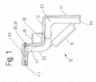
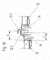
- FIG. 1 shows the Sprintsungsschutz 12 according to the invention, consisting of the base plate 1.1 with its folded portion 1.2, which has approximately a right angle relative to the base plate 1.1 and is bent in its further course a further time, the further fold approximately at right angles to the first Has a fold.
- a stiffening angle 21 is arranged between the horizontal and the vertical part of the folded base plate 1.2, on both sides of a cover plate 22 is arranged.
- On both sides of the base plate 1.1 and the folded base plate 1.2 are arranged in the lower region webs 2.1, which are bent down.
- the fold 2.4 is designed in the present case, that it connects both bevelled webs 2.1 with each other, wherein the webs 2.1 and the fold 2.4 consist of a single part.
- a stiffener 16 which is angled in their inclined to the rail area to increase their buckling strength.
- the stiffening 16 serves to stabilize the overbuffering protection 12 in the lower region, while the stabilization in the upper region is achieved by the stiffening angle 21.
- the over-buffering protection 12 is covered by the cover plate 9.1, 9.2, one side of the over-buffering protection 12.1 being provided with a fixed cover plate 9.1 and the other side of the over-buffering protection 12.2 with a displaceable cover plate 9.2. Under the cover plate 9.1, 9.2 are for stabilization ribs 5.1, 5.2.
- bump lips 4 are arranged on the over-buffering protection, which is a fixed butt lip 4.1 and a slidable in the direction of travel of the car push lip 4.2.
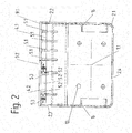
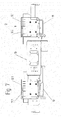
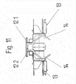
- FIG. 2 shows the overfill protection 12 for a railroad car in front view.
- the view shows that the base plate 1.1 has a hole pattern 10 for fixing the base plate 1.1 between the base frame 13 and crash buffer 14, wherein four symmetrically arranged holes are present.
- the lower web 2.1 is folded down, the fold 2.4 connects the two lower webs 2.1 together.
- the stiffener 16 between the webs 2.1 and 2.2 and 2.1 and 2.3 is bent to the vertical center line, creating a higher stability of this stiffener 16 is formed.
- the over-buffer protection 12 is executed differently. Basically, the elements on the upper right side of the drawing are fixed, ie executed immovable, while the elements on the upper left portion of the drawing relative to the lower part of the Matterpuffersungstikes 12 in the direction of travel of the wagon are displaceable. Ribs 5.1, which are fixed, are in the right part of the FIG.
- the over-buffering protection 12.1 has a high stability in this area.
- the upper left area of the over-buffering protection 12.2 has three ribs 5.2, which are displaceable, so that the pusher lip 4.2 and the cover plate 9.2 relative to the Kochpuff ceremoniesstik 12.2 is displaced.
- 12 two guide pins 27 are arranged in two sockets 23 in this area of the Studentspuffersungstikes, as well as in the Figures 3 . 4 and 5 is shown.
- the guide pins 27 are movable in the sockets 23.
- the FIG. 2 further shows that the movable part of the over-buffering protection is made wider than the fixed part.
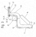
- FIG. 3 shows the Sprintsmann 12 for a railway car from the side of the flexible or sliding abutment lip 4.2, on which the sliding cover plate 9.2 is arranged, with discs 24 and screws 25 provide the connection between the folded portion of the base plate 1.2 and the guide pin 27.
- the buffering protection 12 views are provided on the buffering protection 12 from above and below.
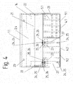
- FIG. 4 shows the over-buffering protection 12 in a schematic representation in a view from above.
- the hole pattern 20 of the coupler handle 19 is arranged, consisting of two holes.
- the four ribs 5.1 which are fixed, are located under the cover plate 9.1, which is fixed and ends at the fixed impact lip 4.1, wherein the fixed ribs 5.1 are interconnected by stiffeners 28.
- the left side of the FIG. 4 shows the displaceable side of the buffering protection 12.2, on which two guide pins 27 are arranged. These two guide pins 27 are provided with screws 25 with discs 24 which connect the guide pin 27 with the sliding abutment lip 4.2.
- the discs 24 are arranged under the screws 25.
- the bushings 23 represent a guide with a clearance fit for the guide pin 27, ie the guide pin 27 with the butt 4.2, the sliding ribs 5.2 and the cover plate 9.2 are in the direction of travel in the sockets 23 displaced.
- the bushes 23 are arranged on the side of the guide pin 27, which is opposite to the impact lip 4.2.
- a locking plate 26 is disposed at one end of the guide pin 27.
- FIG. 5 An illustration of the overfill protection 12 for a railroad car in view from below shows the FIG. 5 , This figure again shows the hole pattern 20 for the coupler handle 19 in the fold 2.4 and the angled stiffener 16 between the webs 2.1 and 2.2 or 2.1 and 2.3.
- On the right side of the illustration are the four fixed or fixed ribs 5.1, which are interconnected and stabilized by stiffeners 28, and the fixed butt lip 4.1 and the cover sheet 9.1.
- the left side of the illustration shows three sliding ribs 9.2 between two guide pins 27 and two bushes 23, wherein ribs 5.3 are arranged on the bushes 23 for stabilization.
- the locking plate 26 is arranged. The locking plate 26 ensures that the guide pin 27 with the sliding abutment lip 4.2, the sliding ribs 5.2 and the sliding cover 9.2 is not against the two sockets 23 slidably.
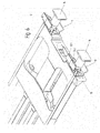
- FIG. 6 shows the over-buffering protection 12 on the base frame 13 and the crash buffers 14. At the buffering protection 12 each of the coupler handle 19 is arranged.
- the over-buffering protection 12 has a fixed side 12.1 and a displaceable side 12.2.
- FIG. 7 shows the Matterpuffersungstik 12 on the undercarriage 13 of a railway carriage, wherein the overbuffer 12 is the coupler handle 19 is arranged and the Studentspuffersungstik 12 on the right side fixed parts of the Matterpuffersungstikes 12.1 and on the left side sliding parts of the Matterpuffersungstikes 12.2 are arranged.
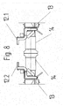
- FIG. 8 shows two car ends, consisting of the undercarriage 13, the Matterpuff ceremoniesstik 12 and the crash buffer 14, wherein the crash buffer 14 are at the same height level and are not depressed.
- the respective fixed side of the over-buffering protection 12.1 and the displaceable side of the over-buffering protection 12.2 face each other. In this way, the overbuffer protectors 12 are basically mounted.
- FIG. 9 shows a similar situation as the FIG. 8 , wherein the crash buffers 14 are pressed in and move in the elastic region.
- the Crash buffer 14 at different height level.
- the cause may be a different loading, a different wear of the wheels or an upgrade of a crash buffer 14 relative to the other crash buffer 14.
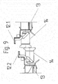
- FIG. 10 shows the representation of FIG. 9 wherein the crash buffer 14 of the higher-level carriage acts against the over-buffering protection 12, 12.1, 12.2 above the crash buffer 14 of the lower-lying left-hand car.
- the length 8 of the over-buffering protection 12, 12.2, 12.1 is greater than the length 3 of the inserted crash buffer 14th
- the FIG. 11 shows two car ends, consisting of the base 13, the over-buffering protection 12, 12.1, 12.2 and the crash buffers 14. Both crash buffers are in one plane, ie both cars have about the same load or wear of the wheels or none of the crash buffer 14 is opposite ascended the other crash buffer.
- Each over-buffering protection 12, 12.1, 12.2 acts under these circumstances against the respective other over-buffering protection, with the result that the displaceable pages 12.2 of the over-buffering protection are shifted with respect to the flexible pages of the over-buffering protection 12.1. That's the one too FIG. 12 refer to.
- the FIG. 11 further shows stiffeners 16 which have been made with less stability.
- FIG. 12 shows the two car ends of FIG. 11 in a view from above, wherein the arranged on the crash buffers 14 and the undercarriage 13 of the railway wagons Matterpuffersungstik 12 in such a way against each other, that the respective narrower and fixed side of the Matterpuffersungstikes 12.1 each wider and movable side of the Matterpuffersungstikes 12.2 in the direction of travel and in Moves towards the base frame 13 so that no damage to the over-buffering protection 12 are expected in such a crash.
- FIG. 13 shows the end of a tank car with Kochpuff ceremoniesstik 12.1, 12.2 above the crash buffer 14 in a perspective view from the front, wherein under the crash buffer 14 of the coupler handle 19 is arranged on the fold 2.4 of the web 2.1 and in the folded portion of the base plate 1.2, the flexible 12.1 and the slidable page 12.2 of the buffering protection are arranged.
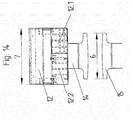
- FIG. 14 shows the overfill protection 12 for a railroad car in a schematic representation and in top view, wherein the buffering protection 12 consists of a displaceable side 12.2 and a fixed side 12.1, wherein the width 7 of the Overfill protection is greater than the buffer width 6 of a buffer 15 or a crash buffer 14th
- FIG. 15 shows the overfill protection 12 for a railroad car in a schematic representation and a view from the side in a crash with a buffer 15 of another railway wagon, which has no over-buffering protection 12, 12.1, 12.2 and is at a higher level.
Landscapes
- Engineering & Computer Science (AREA)
- Mechanical Engineering (AREA)
- Vibration Dampers (AREA)
Priority Applications (2)
| Application Number | Priority Date | Filing Date | Title |
|---|---|---|---|
| PL14169316T PL2808222T3 (pl) | 2013-05-29 | 2014-05-21 | Nadbuforowe zabezpieczenie dla pojazdów szynowych |
| SI201431075T SI2808222T1 (sl) | 2013-05-29 | 2014-05-21 | Varovalni nastavek naletnega odbojnika za železniška vozila |
Applications Claiming Priority (2)
| Application Number | Priority Date | Filing Date | Title |
|---|---|---|---|
| DE102013009121.7A DE102013009121B3 (de) | 2013-05-29 | 2013-05-29 | Überpufferungsschutz für Schienenfahrzeuge |
| DE102013213408.8A DE102013213408A1 (de) | 2013-07-09 | 2013-07-09 | Zwangsbelüftungs- und Vakuum-Sicherheitsventil für einen Tank |
Publications (2)
| Publication Number | Publication Date |
|---|---|
| EP2808222A1 true EP2808222A1 (fr) | 2014-12-03 |
| EP2808222B1 EP2808222B1 (fr) | 2018-11-14 |
Family
ID=51795160
Family Applications (1)
| Application Number | Title | Priority Date | Filing Date |
|---|---|---|---|
| EP14169316.8A Active EP2808222B1 (fr) | 2013-05-29 | 2014-05-21 | Protection contre l'enchevêtrement pour véhicules ferroviaires |
Country Status (2)
| Country | Link |
|---|---|
| EP (1) | EP2808222B1 (fr) |
| PL (1) | PL2808222T3 (fr) |
Cited By (2)
| Publication number | Priority date | Publication date | Assignee | Title |
|---|---|---|---|---|
| CN104859432A (zh) * | 2015-06-10 | 2015-08-26 | 安徽安凯汽车股份有限公司 | 客车油箱侧碰撞保护结构 |
| CN113471593A (zh) * | 2021-07-06 | 2021-10-01 | 中车资阳机车有限公司 | 一种可拆卸动力电池箱防撞结构及其安装方法 |
Citations (11)
| Publication number | Priority date | Publication date | Assignee | Title |
|---|---|---|---|---|
| DE8705085U1 (fr) | 1987-04-04 | 1987-07-02 | Ibeg Maschinen- Und Geraetebau Gmbh, 4370 Marl, De | |
| EP0532442A1 (fr) * | 1991-09-12 | 1993-03-17 | DE DIETRICH & Cie, Société Anonyme dite | Dispositif d'antichevauchement et d'absorption d'énergie pour véhicules ferroviaires |
| DE19626496A1 (de) | 1996-07-02 | 1998-01-08 | Linke Hofmann Busch | Behälterschutzeinrichtung für Schienenfahrzeuge, insbesondere für Kessel- oder geschlossene Schüttgutwagen |
| DE19833935A1 (de) * | 1997-07-28 | 1999-02-04 | Hutchinson | Schutzvorrichtung für einen Behälter zum Einschluß von Werkstoffen und Eisenbahnwaggons, welche zumindest eine dieser Vorrichtung enthalten |
| EP1310416A1 (fr) | 2001-11-09 | 2003-05-14 | ALSTOM LHB GmbH | Dispositif de protection anti-collision pour véhicules ferroviaires |
| EP1306281B1 (fr) | 2001-10-26 | 2007-06-06 | Siemens Aktiengesellschaft | Dispositif d'anti-chevauchement pour véhicules ferroviaires avec tampons latéraux |
| DE102006033161A1 (de) * | 2006-07-18 | 2008-01-24 | Vossloh Locomotives Gmbh | Vorrichtung für Lokomotiven |
| DE102008048247B3 (de) * | 2008-09-16 | 2009-09-10 | Vossloh Locomotives Gmbh | Aufkletterschutz für Puffer an Lokomotiven |
| EP1849677B1 (fr) | 2006-02-10 | 2010-03-10 | Waggonbau Graaff GmbH | Protection anti-chevauchement pour véhicules ferroviaires, en particulier pour wagons-citernes |
| EP2033868B1 (fr) | 2007-09-07 | 2012-04-25 | Ateliers d'Orval | Dispositif anti-chevauchement pour wagons de chemins de fer, en particulier wagons-citernes |
| DE102012221313B3 (de) | 2012-11-22 | 2014-01-02 | Waggonbau Graaff Gmbh | Überpufferungsschutz für Schienenfahrzeuge |
-
2014
- 2014-05-21 PL PL14169316T patent/PL2808222T3/pl unknown
- 2014-05-21 EP EP14169316.8A patent/EP2808222B1/fr active Active
Patent Citations (11)
| Publication number | Priority date | Publication date | Assignee | Title |
|---|---|---|---|---|
| DE8705085U1 (fr) | 1987-04-04 | 1987-07-02 | Ibeg Maschinen- Und Geraetebau Gmbh, 4370 Marl, De | |
| EP0532442A1 (fr) * | 1991-09-12 | 1993-03-17 | DE DIETRICH & Cie, Société Anonyme dite | Dispositif d'antichevauchement et d'absorption d'énergie pour véhicules ferroviaires |
| DE19626496A1 (de) | 1996-07-02 | 1998-01-08 | Linke Hofmann Busch | Behälterschutzeinrichtung für Schienenfahrzeuge, insbesondere für Kessel- oder geschlossene Schüttgutwagen |
| DE19833935A1 (de) * | 1997-07-28 | 1999-02-04 | Hutchinson | Schutzvorrichtung für einen Behälter zum Einschluß von Werkstoffen und Eisenbahnwaggons, welche zumindest eine dieser Vorrichtung enthalten |
| EP1306281B1 (fr) | 2001-10-26 | 2007-06-06 | Siemens Aktiengesellschaft | Dispositif d'anti-chevauchement pour véhicules ferroviaires avec tampons latéraux |
| EP1310416A1 (fr) | 2001-11-09 | 2003-05-14 | ALSTOM LHB GmbH | Dispositif de protection anti-collision pour véhicules ferroviaires |
| EP1849677B1 (fr) | 2006-02-10 | 2010-03-10 | Waggonbau Graaff GmbH | Protection anti-chevauchement pour véhicules ferroviaires, en particulier pour wagons-citernes |
| DE102006033161A1 (de) * | 2006-07-18 | 2008-01-24 | Vossloh Locomotives Gmbh | Vorrichtung für Lokomotiven |
| EP2033868B1 (fr) | 2007-09-07 | 2012-04-25 | Ateliers d'Orval | Dispositif anti-chevauchement pour wagons de chemins de fer, en particulier wagons-citernes |
| DE102008048247B3 (de) * | 2008-09-16 | 2009-09-10 | Vossloh Locomotives Gmbh | Aufkletterschutz für Puffer an Lokomotiven |
| DE102012221313B3 (de) | 2012-11-22 | 2014-01-02 | Waggonbau Graaff Gmbh | Überpufferungsschutz für Schienenfahrzeuge |
Cited By (3)
| Publication number | Priority date | Publication date | Assignee | Title |
|---|---|---|---|---|
| CN104859432A (zh) * | 2015-06-10 | 2015-08-26 | 安徽安凯汽车股份有限公司 | 客车油箱侧碰撞保护结构 |
| CN104859432B (zh) * | 2015-06-10 | 2017-12-19 | 安徽安凯汽车股份有限公司 | 客车油箱侧碰撞保护结构 |
| CN113471593A (zh) * | 2021-07-06 | 2021-10-01 | 中车资阳机车有限公司 | 一种可拆卸动力电池箱防撞结构及其安装方法 |
Also Published As
| Publication number | Publication date |
|---|---|
| EP2808222B1 (fr) | 2018-11-14 |
| PL2808222T3 (pl) | 2019-04-30 |
Similar Documents
| Publication | Publication Date | Title |
|---|---|---|
| DE3911138C2 (fr) | ||
| DE102013009121B3 (de) | Überpufferungsschutz für Schienenfahrzeuge | |
| EP2999609B1 (fr) | Véhicule ferroviaire à système d'attelage entrant entièrement dans la structure | |
| EP1875002B1 (fr) | Dispositif pour le transport de tronçons de voie ou de raccordements de voies assembles | |
| EP2837542B1 (fr) | Châssis de véhicule pour un porte-conteneurs et porte-conteneurs | |
| EP2808222B1 (fr) | Protection contre l'enchevêtrement pour véhicules ferroviaires | |
| DE102010014596A1 (de) | Fahrzeug zur Durchführung von Baumaßnahmen im Gleisbereich des Eisenbahnverkehrs | |
| DE102012221313B3 (de) | Überpufferungsschutz für Schienenfahrzeuge | |
| WO2018108332A1 (fr) | Dispositif de transport | |
| DE4332289A1 (de) | Vorrichtung zum Verhindern des Aufkletterns von Schienenfahrzeugen als Folge eines unfallbedingten Aufpralls | |
| DE1225690B (de) | Eisenbahnwagen zum Transport von Lastbehaeltern | |
| EP3560787B1 (fr) | Véhicule sur rail | |
| DE1680377C3 (de) | Transporteinheit aus mindestens zwei zweiachsigen Schienenfahrzeugen | |
| DE19626496A1 (de) | Behälterschutzeinrichtung für Schienenfahrzeuge, insbesondere für Kessel- oder geschlossene Schüttgutwagen | |
| EP0182138B1 (fr) | Châssis pour wagons ferroviaires à marchandises | |
| EP3608197B1 (fr) | Dispositif anti-chevauchement pourvu d'élément d'écran de protection | |
| DE924870C (de) | Durchgehende Zug- und Stossvorrichtung fuer Eisenbahnwagenuntergestelle | |
| EP3768565B1 (fr) | Interface pour relier une carrosserie de véhicule à un châssis | |
| EP0507109B1 (fr) | Dispositif d'appui et de guidage pour le logement d'une poutre centrale de tamponnement dans le chassis d'un véhicule ferroviaire | |
| EP1321342B1 (fr) | Wagon et méthode pour le transport de semi-remorques | |
| DE102016216719A1 (de) | Querweiches Einfachgelenk mit angenäherter Geradführung mittels Deichsel | |
| AT16474U1 (de) | Crashkonzept Stadt-Regio-Fahrzeug | |
| DE102020128722A1 (de) | Fahrwerk für ein Fahrzeug | |
| AT400946B (de) | Chassis für raupenfahrwerke | |
| AT233047B (de) | Eisenbahnwagen |
Legal Events
| Date | Code | Title | Description |
|---|---|---|---|
| PUAI | Public reference made under article 153(3) epc to a published international application that has entered the european phase |
Free format text: ORIGINAL CODE: 0009012 |
|
| 17P | Request for examination filed |
Effective date: 20140521 |
|
| AK | Designated contracting states |
Kind code of ref document: A1 Designated state(s): AL AT BE BG CH CY CZ DE DK EE ES FI FR GB GR HR HU IE IS IT LI LT LU LV MC MK MT NL NO PL PT RO RS SE SI SK SM TR |
|
| AX | Request for extension of the european patent |
Extension state: BA ME |
|
| R17P | Request for examination filed (corrected) |
Effective date: 20150423 |
|
| RBV | Designated contracting states (corrected) |
Designated state(s): AL AT BE BG CH CY CZ DE DK EE ES FI FR GB GR HR HU IE IS IT LI LT LU LV MC MK MT NL NO PL PT RO RS SE SI SK SM TR |
|
| GRAP | Despatch of communication of intention to grant a patent |
Free format text: ORIGINAL CODE: EPIDOSNIGR1 |
|
| STAA | Information on the status of an ep patent application or granted ep patent |
Free format text: STATUS: GRANT OF PATENT IS INTENDED |
|
| INTG | Intention to grant announced |
Effective date: 20180622 |
|
| GRAS | Grant fee paid |
Free format text: ORIGINAL CODE: EPIDOSNIGR3 |
|
| GRAA | (expected) grant |
Free format text: ORIGINAL CODE: 0009210 |
|
| STAA | Information on the status of an ep patent application or granted ep patent |
Free format text: STATUS: THE PATENT HAS BEEN GRANTED |
|
| AK | Designated contracting states |
Kind code of ref document: B1 Designated state(s): AL AT BE BG CH CY CZ DE DK EE ES FI FR GB GR HR HU IE IS IT LI LT LU LV MC MK MT NL NO PL PT RO RS SE SI SK SM TR |
|
| REG | Reference to a national code |
Ref country code: CH Ref legal event code: EP Ref country code: AT Ref legal event code: REF Ref document number: 1064453 Country of ref document: AT Kind code of ref document: T Effective date: 20181115 |
|
| REG | Reference to a national code |
Ref country code: DE Ref legal event code: R096 Ref document number: 502014010034 Country of ref document: DE |
|
| REG | Reference to a national code |
Ref country code: IE Ref legal event code: FG4D Free format text: LANGUAGE OF EP DOCUMENT: GERMAN |
|
| REG | Reference to a national code |
Ref country code: RO Ref legal event code: EPE |
|
| REG | Reference to a national code |
Ref country code: NL Ref legal event code: MP Effective date: 20181114 |
|
| REG | Reference to a national code |
Ref country code: LT Ref legal event code: MG4D |
|
| PG25 | Lapsed in a contracting state [announced via postgrant information from national office to epo] |
Ref country code: FI Free format text: LAPSE BECAUSE OF FAILURE TO SUBMIT A TRANSLATION OF THE DESCRIPTION OR TO PAY THE FEE WITHIN THE PRESCRIBED TIME-LIMIT Effective date: 20181114 Ref country code: BG Free format text: LAPSE BECAUSE OF FAILURE TO SUBMIT A TRANSLATION OF THE DESCRIPTION OR TO PAY THE FEE WITHIN THE PRESCRIBED TIME-LIMIT Effective date: 20190214 Ref country code: HR Free format text: LAPSE BECAUSE OF FAILURE TO SUBMIT A TRANSLATION OF THE DESCRIPTION OR TO PAY THE FEE WITHIN THE PRESCRIBED TIME-LIMIT Effective date: 20181114 Ref country code: NO Free format text: LAPSE BECAUSE OF FAILURE TO SUBMIT A TRANSLATION OF THE DESCRIPTION OR TO PAY THE FEE WITHIN THE PRESCRIBED TIME-LIMIT Effective date: 20190214 Ref country code: LT Free format text: LAPSE BECAUSE OF FAILURE TO SUBMIT A TRANSLATION OF THE DESCRIPTION OR TO PAY THE FEE WITHIN THE PRESCRIBED TIME-LIMIT Effective date: 20181114 Ref country code: IS Free format text: LAPSE BECAUSE OF FAILURE TO SUBMIT A TRANSLATION OF THE DESCRIPTION OR TO PAY THE FEE WITHIN THE PRESCRIBED TIME-LIMIT Effective date: 20190314 Ref country code: ES Free format text: LAPSE BECAUSE OF FAILURE TO SUBMIT A TRANSLATION OF THE DESCRIPTION OR TO PAY THE FEE WITHIN THE PRESCRIBED TIME-LIMIT Effective date: 20181114 Ref country code: LV Free format text: LAPSE BECAUSE OF FAILURE TO SUBMIT A TRANSLATION OF THE DESCRIPTION OR TO PAY THE FEE WITHIN THE PRESCRIBED TIME-LIMIT Effective date: 20181114 |
|
| PG25 | Lapsed in a contracting state [announced via postgrant information from national office to epo] |
Ref country code: AL Free format text: LAPSE BECAUSE OF FAILURE TO SUBMIT A TRANSLATION OF THE DESCRIPTION OR TO PAY THE FEE WITHIN THE PRESCRIBED TIME-LIMIT Effective date: 20181114 Ref country code: SE Free format text: LAPSE BECAUSE OF FAILURE TO SUBMIT A TRANSLATION OF THE DESCRIPTION OR TO PAY THE FEE WITHIN THE PRESCRIBED TIME-LIMIT Effective date: 20181114 Ref country code: RS Free format text: LAPSE BECAUSE OF FAILURE TO SUBMIT A TRANSLATION OF THE DESCRIPTION OR TO PAY THE FEE WITHIN THE PRESCRIBED TIME-LIMIT Effective date: 20181114 Ref country code: GR Free format text: LAPSE BECAUSE OF FAILURE TO SUBMIT A TRANSLATION OF THE DESCRIPTION OR TO PAY THE FEE WITHIN THE PRESCRIBED TIME-LIMIT Effective date: 20190215 Ref country code: PT Free format text: LAPSE BECAUSE OF FAILURE TO SUBMIT A TRANSLATION OF THE DESCRIPTION OR TO PAY THE FEE WITHIN THE PRESCRIBED TIME-LIMIT Effective date: 20190314 Ref country code: NL Free format text: LAPSE BECAUSE OF FAILURE TO SUBMIT A TRANSLATION OF THE DESCRIPTION OR TO PAY THE FEE WITHIN THE PRESCRIBED TIME-LIMIT Effective date: 20181114 |
|
| REG | Reference to a national code |
Ref country code: SK Ref legal event code: T3 Ref document number: E 30096 Country of ref document: SK |
|
| PG25 | Lapsed in a contracting state [announced via postgrant information from national office to epo] |
Ref country code: DK Free format text: LAPSE BECAUSE OF FAILURE TO SUBMIT A TRANSLATION OF THE DESCRIPTION OR TO PAY THE FEE WITHIN THE PRESCRIBED TIME-LIMIT Effective date: 20181114 |
|
| REG | Reference to a national code |
Ref country code: DE Ref legal event code: R097 Ref document number: 502014010034 Country of ref document: DE |
|
| PG25 | Lapsed in a contracting state [announced via postgrant information from national office to epo] |
Ref country code: EE Free format text: LAPSE BECAUSE OF FAILURE TO SUBMIT A TRANSLATION OF THE DESCRIPTION OR TO PAY THE FEE WITHIN THE PRESCRIBED TIME-LIMIT Effective date: 20181114 Ref country code: SM Free format text: LAPSE BECAUSE OF FAILURE TO SUBMIT A TRANSLATION OF THE DESCRIPTION OR TO PAY THE FEE WITHIN THE PRESCRIBED TIME-LIMIT Effective date: 20181114 |
|
| PLBE | No opposition filed within time limit |
Free format text: ORIGINAL CODE: 0009261 |
|
| STAA | Information on the status of an ep patent application or granted ep patent |
Free format text: STATUS: NO OPPOSITION FILED WITHIN TIME LIMIT |
|
| 26N | No opposition filed |
Effective date: 20190815 |
|
| REG | Reference to a national code |
Ref country code: CH Ref legal event code: PL |
|
| PG25 | Lapsed in a contracting state [announced via postgrant information from national office to epo] |
Ref country code: CH Free format text: LAPSE BECAUSE OF NON-PAYMENT OF DUE FEES Effective date: 20190531 Ref country code: LI Free format text: LAPSE BECAUSE OF NON-PAYMENT OF DUE FEES Effective date: 20190531 Ref country code: MC Free format text: LAPSE BECAUSE OF FAILURE TO SUBMIT A TRANSLATION OF THE DESCRIPTION OR TO PAY THE FEE WITHIN THE PRESCRIBED TIME-LIMIT Effective date: 20181114 |
|
| REG | Reference to a national code |
Ref country code: BE Ref legal event code: MM Effective date: 20190531 |
|
| PG25 | Lapsed in a contracting state [announced via postgrant information from national office to epo] |
Ref country code: LU Free format text: LAPSE BECAUSE OF NON-PAYMENT OF DUE FEES Effective date: 20190521 |
|
| PG25 | Lapsed in a contracting state [announced via postgrant information from national office to epo] |
Ref country code: TR Free format text: LAPSE BECAUSE OF FAILURE TO SUBMIT A TRANSLATION OF THE DESCRIPTION OR TO PAY THE FEE WITHIN THE PRESCRIBED TIME-LIMIT Effective date: 20181114 |
|
| PG25 | Lapsed in a contracting state [announced via postgrant information from national office to epo] |
Ref country code: IE Free format text: LAPSE BECAUSE OF NON-PAYMENT OF DUE FEES Effective date: 20190521 |
|
| PG25 | Lapsed in a contracting state [announced via postgrant information from national office to epo] |
Ref country code: BE Free format text: LAPSE BECAUSE OF NON-PAYMENT OF DUE FEES Effective date: 20190531 |
|
| PG25 | Lapsed in a contracting state [announced via postgrant information from national office to epo] |
Ref country code: FR Free format text: LAPSE BECAUSE OF NON-PAYMENT OF DUE FEES Effective date: 20190531 |
|
| REG | Reference to a national code |
Ref country code: AT Ref legal event code: MM01 Ref document number: 1064453 Country of ref document: AT Kind code of ref document: T Effective date: 20190521 |
|
| PG25 | Lapsed in a contracting state [announced via postgrant information from national office to epo] |
Ref country code: AT Free format text: LAPSE BECAUSE OF NON-PAYMENT OF DUE FEES Effective date: 20190521 |
|
| PG25 | Lapsed in a contracting state [announced via postgrant information from national office to epo] |
Ref country code: CY Free format text: LAPSE BECAUSE OF FAILURE TO SUBMIT A TRANSLATION OF THE DESCRIPTION OR TO PAY THE FEE WITHIN THE PRESCRIBED TIME-LIMIT Effective date: 20181114 |
|
| PG25 | Lapsed in a contracting state [announced via postgrant information from national office to epo] |
Ref country code: MT Free format text: LAPSE BECAUSE OF FAILURE TO SUBMIT A TRANSLATION OF THE DESCRIPTION OR TO PAY THE FEE WITHIN THE PRESCRIBED TIME-LIMIT Effective date: 20181114 Ref country code: HU Free format text: LAPSE BECAUSE OF FAILURE TO SUBMIT A TRANSLATION OF THE DESCRIPTION OR TO PAY THE FEE WITHIN THE PRESCRIBED TIME-LIMIT; INVALID AB INITIO Effective date: 20140521 |
|
| PG25 | Lapsed in a contracting state [announced via postgrant information from national office to epo] |
Ref country code: MK Free format text: LAPSE BECAUSE OF FAILURE TO SUBMIT A TRANSLATION OF THE DESCRIPTION OR TO PAY THE FEE WITHIN THE PRESCRIBED TIME-LIMIT Effective date: 20181114 |
|
| PGFP | Annual fee paid to national office [announced via postgrant information from national office to epo] |
Ref country code: IT Payment date: 20220531 Year of fee payment: 9 |
|
| PGFP | Annual fee paid to national office [announced via postgrant information from national office to epo] |
Ref country code: RO Payment date: 20230510 Year of fee payment: 10 Ref country code: CZ Payment date: 20230510 Year of fee payment: 10 |
|
| PGFP | Annual fee paid to national office [announced via postgrant information from national office to epo] |
Ref country code: SK Payment date: 20230517 Year of fee payment: 10 Ref country code: SI Payment date: 20230508 Year of fee payment: 10 Ref country code: PL Payment date: 20230508 Year of fee payment: 10 |
|
| PGFP | Annual fee paid to national office [announced via postgrant information from national office to epo] |
Ref country code: GB Payment date: 20230522 Year of fee payment: 10 |
|
| PGFP | Annual fee paid to national office [announced via postgrant information from national office to epo] |
Ref country code: DE Payment date: 20230720 Year of fee payment: 10 |
|
| PG25 | Lapsed in a contracting state [announced via postgrant information from national office to epo] |
Ref country code: IT Free format text: LAPSE BECAUSE OF NON-PAYMENT OF DUE FEES Effective date: 20230521 |