EP3768565B1 - Interface pour relier une carrosserie de véhicule à un châssis - Google Patents
Interface pour relier une carrosserie de véhicule à un châssis Download PDFInfo
- Publication number
- EP3768565B1 EP3768565B1 EP19712555.2A EP19712555A EP3768565B1 EP 3768565 B1 EP3768565 B1 EP 3768565B1 EP 19712555 A EP19712555 A EP 19712555A EP 3768565 B1 EP3768565 B1 EP 3768565B1
- Authority
- EP
- European Patent Office
- Prior art keywords
- stop
- plate
- travel
- chassis
- cross member
- Prior art date
- Legal status (The legal status is an assumption and is not a legal conclusion. Google has not performed a legal analysis and makes no representation as to the accuracy of the status listed.)
- Active
Links
- 230000008878 coupling Effects 0.000 claims description 47
- 238000010168 coupling process Methods 0.000 claims description 47
- 238000005859 coupling reaction Methods 0.000 claims description 47
- 125000006850 spacer group Chemical group 0.000 claims description 25
- 238000003780 insertion Methods 0.000 claims description 2
- 230000037431 insertion Effects 0.000 claims description 2
- 238000000465 moulding Methods 0.000 claims description 2
- 241000446313 Lamella Species 0.000 claims 1
- XEEYBQQBJWHFJM-UHFFFAOYSA-N Iron Chemical compound [Fe] XEEYBQQBJWHFJM-UHFFFAOYSA-N 0.000 description 4
- 238000005096 rolling process Methods 0.000 description 4
- 230000001133 acceleration Effects 0.000 description 2
- 229910052742 iron Inorganic materials 0.000 description 2
- 239000010959 steel Substances 0.000 description 2
- 229910001018 Cast iron Inorganic materials 0.000 description 1
- 229910001208 Crucible steel Inorganic materials 0.000 description 1
- 229910000831 Steel Inorganic materials 0.000 description 1
- 229910000746 Structural steel Inorganic materials 0.000 description 1
- 230000003993 interaction Effects 0.000 description 1
- 239000000463 material Substances 0.000 description 1
- 239000002184 metal Substances 0.000 description 1
- 229910052751 metal Inorganic materials 0.000 description 1
- 230000002787 reinforcement Effects 0.000 description 1
- 239000007787 solid Substances 0.000 description 1
Images


Classifications
-
- B—PERFORMING OPERATIONS; TRANSPORTING
- B61—RAILWAYS
- B61D—BODY DETAILS OR KINDS OF RAILWAY VEHICLES
- B61D3/00—Wagons or vans
- B61D3/10—Articulated vehicles
- B61D3/12—Articulated vehicles comprising running gear interconnected by loads
-
- B—PERFORMING OPERATIONS; TRANSPORTING
- B61—RAILWAYS
- B61D—BODY DETAILS OR KINDS OF RAILWAY VEHICLES
- B61D3/00—Wagons or vans
- B61D3/16—Wagons or vans adapted for carrying special loads
- B61D3/20—Wagons or vans adapted for carrying special loads for forwarding containers
-
- B—PERFORMING OPERATIONS; TRANSPORTING
- B60—VEHICLES IN GENERAL
- B60P—VEHICLES ADAPTED FOR LOAD TRANSPORTATION OR TO TRANSPORT, TO CARRY, OR TO COMPRISE SPECIAL LOADS OR OBJECTS
- B60P7/00—Securing or covering of load on vehicles
- B60P7/06—Securing of load
- B60P7/13—Securing freight containers or forwarding containers on vehicles
-
- B—PERFORMING OPERATIONS; TRANSPORTING
- B61—RAILWAYS
- B61D—BODY DETAILS OR KINDS OF RAILWAY VEHICLES
- B61D45/00—Means or devices for securing or supporting the cargo, including protection against shocks
- B61D45/007—Fixing containers
Definitions
- a particularly good force dissipation is made possible by an inventive design of the stop plate for support on a main cross member in the area of the chassis; Furthermore, when the force is introduced, the particularly short lever arm results in a particularly low tilting moment.
- the recess on the vehicle body for receiving the first coupling element, in particular the pin has a larger dimension than the pin itself, at least in the direction of travel, but preferably also transversely to the direction of travel. This ensures during operation that at least parallel to the direction of travel, but possibly also transversely to the direction of travel, a certain freedom of movement, i.e. play, X remains for the movement of the pin in the recess, preferably in the direction of travel, but also transversely to the direction of travel.
- the second coupling element comprises a preferably one-piece stop bracket with a fastening plate and a stop plate oriented essentially at 90° thereto.
- stop bracket is connected to the underside of the vehicle body, it is not connected to the underframe, so that movements in a direction transverse to the direction of travel, for example when cornering, remain possible.
- the stop bracket can divert movements of the vehicle body in the direction of travel as well as against the direction of travel into the cross member or main cross member.
- a molded part is provided on the mounting plate for insertion into a recess on the underside of the vehicle body for positioning the stop bracket.
- a molded part can have a raised rectangular shape, for example.
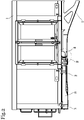
- the second coupling elements 4 which transmit longitudinal forces of the vehicle body to the main cross member 8 in the form of a 90° angle.
- first coupling elements 3 and second coupling elements 4 can also be provided at the other end of the underframe 2 .
- a shoulder 17 which is arranged on the main cross member 8 is also shown.
- the shoulder 17 extends backwards in the direction of travel in such a way that upward removal of the stop bracket 10 or the vehicle body 1 is counteracted.
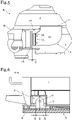
- Fig. 12 shows a schematic view of section AA 4 .
- the first coupling element 3 is shown in a schematic sectional representation.
- the first coupling element 3 includes a pin 6 which is arranged on the main cross member 8 .
- the pin has a substantially circular cross-section and is designed with a reduced cross-section towards the top in order to make it easier to place the vehicle body 1 on the underframe 2 .
- the recess 5 can also have a substantially circular cross-section. In the vertical direction, the recess 5 or the chamber formed is sufficient to be able to completely accommodate the pin 6 .
- the recess 5 is significantly larger than the peg 6.
- the diameter of the pegs is Z and the recess has a size of approximately Z+2X.
- X is about a quarter of the diameter of the pin 6, but other dimensions are of course also provided according to the invention.
- the shoulder 17 shown extends a distance greater than 2Y, and preferably greater than X+Y, beyond the stop 14 to ensure that even if the vehicle body is displaced in a rearward direction, the stop bracket 10 will not be removed vertically upwards can be.
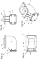
- FIGS 7a - 7d show schematic views of the second coupling element 4 according to the invention.
- This includes a stop bracket 10, which is designed as a substantially 90° angle iron.
- a mounting plate 11 At one end of the fence bracket 10 is a mounting plate 11. This is generally rectangular or square.
- a molded part 15 is arranged on the fastening plate 11 and is used for the correct positioning of the fastening plate 11 on the underside of the vehicle body 1 .
- the mounting plate 11 is in the form of a substantially rectangular flange with mounting holes.
- stop bracket 10 At the other end of the stop bracket 10 there is a stop plate 12 onto which a spacer plate 13 is screwed.
- the spacer plate 13 is firmly connected to the stop plate 12 via screws and nuts, but other connection options can also be provided.
- All components of the anchor bracket 10 can be made of iron, cast iron or steel.
Claims (13)
- Interface pour relier une caisse de véhicule (1) à un châssis (2) d'un véhicule ferroviaire, comprenant au moins un premier élément de couplage (3) qui est réalisé pour dissiper des forces s'étendant sensiblement de manière normale à la direction de déplacement, dans laquelle au moins un deuxième élément de couplage (4) est prévu, qui est réalisé pour dissiper des forces s'étendant sensiblement de manière parallèle à la direction de déplacement,caractérisée en ce quele deuxième élément de couplage (4) comprend une console de butée (10), de préférence monobloc, avec une plaque de fixation (11) et une plaque de butée (12) orientée sensiblement à 90° par rapport à celle-ci, la plaque de fixation (11) étant réalisée pour être fixée de manière amovible sur la face inférieure de la caisse de véhicule (1),et la plaque de butée (12) est conçue pour s'appuyer sur une butée (14) d'une traverse (7), de préférence d'une traverse principale (8) dans la zone du bogie (9) du châssis (2).
- Interface selon la revendication 1, caractérisée en ce que le premier élément de couplage (3) comprend un tenon (6) orienté vers le haut, sensiblement de manière normale à la direction de déplacement, de préférence verticalement par rapport au châssis (2), et conçu pour s'engager dans un évidement (5) sur la face inférieure de la caisse de véhicule (1).
- Interface selon la revendication 2, caractérisée en ce que le tenon (6) est prévu pour être disposé sur une traverse (7), de préférence sur une traverse principale (8) dans la zone d'un bogie (9), du châssis (2).
- Interface selon l'une des revendications 1 à 3, caractérisée en ce qu'une plaque d'écartement (13) est disposée sur la plaque de butée (12) pour régler une distance Y définie entre la console de butée (10) et le châssis (2).
- Interface selon la revendication 4, caractérisée en ce que la plaque d'écartement (13) est fixée, en particulier vissée, enfichée ou insérée, sur la plaque de butée (12) de telle sorte qu'elle peut être retirée ou remplacée même lorsque la plaque de fixation (11) est fixée sur la face inférieure de la caisse de véhicule et que la plaque de butée (12) est directement en contact avec la butée (14).
- Interface selon l'une des revendications 1 à 5, caractérisée en ce qu'une pièce moulée (15) est prévue sur la plaque de fixation (11) pour être introduite dans un évidement sur la face inférieure de la caisse de véhicule (1) pour positionner la console de butée (10).
- Interface selon l'une des revendications 1 à 6, caractérisée en ce que la plaque de fixation (11) et la plaque de butée (12) sont reliées entre elles par une pluralité, de préférence trois, de tôles, lamelles ou nervures (16) de forme sensiblement rectangulaire.
- Arrangement comprenant une caisse de véhicule (1), un châssis (2) comprenant au moins un bogie (9), et au moins une interface selon l'une des revendications 1 à 7.
- Arrangement selon la revendication 8, comprenant une interface selon l'une des revendications 2 à 7, caractérisé en ce que l'évidement (5) sur la caisse de véhicule (1) destiné à recevoir le tenon (6) dans la direction de déplacement présente une dimension supérieure à celle du tenon (6), de sorte qu'en fonctionnement, au moins parallèlement à la direction de déplacement, il subsiste un jeu X pour le déplacement du tenon (6) dans l'évidement (5) dans la direction de déplacement.
- Arrangement selon la revendication 9, dans lequel l'interface est réalisée selon l'une des revendications 4 à 7, caractérisé en ce que la distance Y entre la console de butée (10) et le châssis (2) est inférieure au jeu X pour le déplacement du tenon (6) dans l'évidement (5) sur la face inférieure de la caisse de véhicule (1).
- Arrangement selon la revendication 10, caractérisé en ce qu'il est prévu sur la traverse (7) ou sur la traverse principale (8) un épaulement (17) qui dépasse la butée (14) de plus de la distance X + Y pour s'opposer à un enlèvement du deuxième élément de couplage (4) dans une direction verticale.
- Arrangement selon l'une des revendications 8 à 11, caractérisé en ce qu'il est prévu une pluralité d'interfaces, les interfaces étant disposées chacune dans la zone d'un bogie (9) du châssis (2).
- Arrangement selon la revendication 12, caractérisé en ce que le châssis (2) comprend deux traverses principales (8) avec respectivement deux châssis (9), une interface selon l'une des revendications 1 à 12 étant disposée sur chaque traverse principale (8) respectivement dans la zone du bogie (9).
Priority Applications (3)
| Application Number | Priority Date | Filing Date | Title |
|---|---|---|---|
| RS20230246A RS64089B1 (sr) | 2018-03-21 | 2019-03-19 | Međuspoj za spajanje karoserije vozila sa šasijom |
| HRP20230307TT HRP20230307T1 (hr) | 2018-03-21 | 2019-03-19 | Međuspoj za spajanje karoserije vozila sa šasijom |
| SI201930492T SI3768565T1 (sl) | 2018-03-21 | 2019-03-19 | Vmesnik za povezovanje superstrukture vozila z ogrodjem |
Applications Claiming Priority (2)
| Application Number | Priority Date | Filing Date | Title |
|---|---|---|---|
| ATA50236/2018A AT521070B1 (de) | 2018-03-21 | 2018-03-21 | Schnittstelle zur Verbindung eines Fahrzeugaufbaus mit einem Untergestell |
| PCT/EP2019/056746 WO2019179965A1 (fr) | 2018-03-21 | 2019-03-19 | Interface pour relier une carrosserie de véhicule à un châssis |
Publications (2)
| Publication Number | Publication Date |
|---|---|
| EP3768565A1 EP3768565A1 (fr) | 2021-01-27 |
| EP3768565B1 true EP3768565B1 (fr) | 2022-12-28 |
Family
ID=65861278
Family Applications (1)
| Application Number | Title | Priority Date | Filing Date |
|---|---|---|---|
| EP19712555.2A Active EP3768565B1 (fr) | 2018-03-21 | 2019-03-19 | Interface pour relier une carrosserie de véhicule à un châssis |
Country Status (10)
| Country | Link |
|---|---|
| EP (1) | EP3768565B1 (fr) |
| CN (1) | CN111699123B (fr) |
| AT (1) | AT521070B1 (fr) |
| HR (1) | HRP20230307T1 (fr) |
| HU (1) | HUE061568T2 (fr) |
| PL (1) | PL3768565T3 (fr) |
| RS (1) | RS64089B1 (fr) |
| RU (1) | RU2748626C1 (fr) |
| SI (1) | SI3768565T1 (fr) |
| WO (1) | WO2019179965A1 (fr) |
Family Cites Families (23)
| Publication number | Priority date | Publication date | Assignee | Title |
|---|---|---|---|---|
| DE743227C (fr) * | 1940-11-27 | 1943-12-21 | ||
| CH163168A (de) * | 1932-08-25 | 1933-07-31 | Schweizerische Wagons & Aufzue | Stossdämpfungseinrichtung an Behälter-Transportwagen. |
| DE1233002B (de) * | 1960-12-08 | 1967-01-26 | Pullman Inc | Auf der Ladeflaeche eines Eisenbahnplattformwagens anbringbarer Frachtbehaelter-Traegerrahmen |
| DE1920051U (de) * | 1963-02-11 | 1965-07-22 | Pullman Inc | Langbehaelter-eisenbahnwagen. |
| US3762340A (en) * | 1972-02-10 | 1973-10-02 | Southern Pacific Transport Co | Container restraint system for railway cars |
| FR2234167A1 (en) * | 1973-06-25 | 1975-01-17 | Grandury Yves | Railway wagon with removable body - body is positioned over pins on bogie top plates and chassis beam |
| FR2250657B1 (fr) * | 1973-11-09 | 1976-05-07 | Interpar | |
| US4597337A (en) * | 1983-12-23 | 1986-07-01 | Elwood Willetts | Low profile intermodal transport system |
| US4864938A (en) * | 1987-10-28 | 1989-09-12 | Trinity Industries, Inc. | Railway freight car |
| US4961676A (en) * | 1987-12-11 | 1990-10-09 | Intermotra | Goods transport systems which are transformable into rail vehicles, and rail bogies for use therewith |
| DE3940650C1 (fr) * | 1989-12-08 | 1990-12-13 | Linke-Hofmann-Busch Waggon-Fahrzeug-Maschinen Gmbh, 3320 Salzgitter, De | |
| DE19507236B4 (de) * | 1995-03-02 | 2005-09-15 | Bartel, Manfred, Dipl.-Ing. (FH) | Großbehältertragwagen für den gemischten Eisenbahntransport von Containern und Wechselbehältern |
| RU42802U1 (ru) * | 2004-09-28 | 2004-12-20 | Морчиладзе Илья Геронтьевич | Вагон со съемным кузовом |
| US7913969B2 (en) * | 2007-06-27 | 2011-03-29 | Ttx Company | Securement clamp system for railcars |
| RU81143U1 (ru) * | 2008-12-03 | 2009-03-10 | Юрий Павлович Бороненко | Платформа для перевозки контейнеров |
| CZ2008795A3 (cs) * | 2008-12-10 | 2010-06-23 | Vads, A.S. | Nástavba dopravních prostredku pro prepravu plochých velkorozmerových predmetu |
| CN102424051A (zh) * | 2011-11-15 | 2012-04-25 | 南车二七车辆有限公司 | 大型散堆货物箱 |
| AT513078A1 (de) * | 2012-04-26 | 2014-01-15 | Siemens Ag Oesterreich | Vorrichtung zur Kraftübertragung zwischen Fahrwerk und Wagenkasten eines Schienenfahrzeugs |
| ES2779758T3 (es) * | 2014-02-10 | 2020-08-19 | Siemens Mobility GmbH | Vehículo ferroviario, en particular locomotora |
| RU167058U1 (ru) * | 2016-05-12 | 2016-12-20 | Общество с ограниченной ответственностью Управляющая Компания "РэйлТрансХолдинг" | Железнодорожная вагон-платформа для перевозки контейнеров повышенной грузоподъемности |
| RU170575U1 (ru) * | 2016-11-30 | 2017-04-28 | РЕЙЛ 1520 АйПи ЛТД | Сочленённый вагон-платформа |
| CN107738657A (zh) * | 2017-09-26 | 2018-02-27 | 中车青岛四方机车车辆股份有限公司 | 一种磁悬浮列车及其无纵梁结构的走行部 |
| CN107791882B (zh) * | 2017-09-26 | 2020-02-14 | 中车青岛四方机车车辆股份有限公司 | 一种磁悬浮列车及其走行部 |
-
2018
- 2018-03-21 AT ATA50236/2018A patent/AT521070B1/de active
-
2019
- 2019-03-19 WO PCT/EP2019/056746 patent/WO2019179965A1/fr unknown
- 2019-03-19 CN CN201980012684.8A patent/CN111699123B/zh active Active
- 2019-03-19 EP EP19712555.2A patent/EP3768565B1/fr active Active
- 2019-03-19 PL PL19712555.2T patent/PL3768565T3/pl unknown
- 2019-03-19 HU HUE19712555A patent/HUE061568T2/hu unknown
- 2019-03-19 RS RS20230246A patent/RS64089B1/sr unknown
- 2019-03-19 HR HRP20230307TT patent/HRP20230307T1/hr unknown
- 2019-03-19 SI SI201930492T patent/SI3768565T1/sl unknown
- 2019-03-19 RU RU2020134073A patent/RU2748626C1/ru active
Also Published As
| Publication number | Publication date |
|---|---|
| CN111699123A (zh) | 2020-09-22 |
| AT521070A1 (de) | 2019-10-15 |
| RS64089B1 (sr) | 2023-04-28 |
| EP3768565A1 (fr) | 2021-01-27 |
| HUE061568T2 (hu) | 2023-07-28 |
| HRP20230307T1 (hr) | 2023-05-12 |
| RU2748626C1 (ru) | 2021-05-28 |
| PL3768565T3 (pl) | 2023-05-08 |
| SI3768565T1 (sl) | 2023-04-28 |
| WO2019179965A1 (fr) | 2019-09-26 |
| AT521070B1 (de) | 2019-12-15 |
| CN111699123B (zh) | 2021-06-22 |
Similar Documents
| Publication | Publication Date | Title |
|---|---|---|
| DE102008039949B4 (de) | Querträger für ein Nutzfahrzeug | |
| EP2841318B1 (fr) | Dispositif de transmission de force entre le châssis et la caisse d'un véhicule ferroviaire | |
| DE102013009121B3 (de) | Überpufferungsschutz für Schienenfahrzeuge | |
| EP3768565B1 (fr) | Interface pour relier une carrosserie de véhicule à un châssis | |
| EP3934961A1 (fr) | Dispositif de support et de centrage destiné à un bras d'attelage d'un attelage ferroviaire automatique | |
| DE102012221313B3 (de) | Überpufferungsschutz für Schienenfahrzeuge | |
| DE102004018052B4 (de) | Unterfahrschutz für ein Kraftfahrzeug | |
| EP2808222B1 (fr) | Protection contre l'enchevêtrement pour véhicules ferroviaires | |
| DE102009016935A1 (de) | Querträger für Kraftfahrzeuge | |
| DE10305937B4 (de) | Kuppelstange mit extremer Längenanpassbarkeit | |
| DE102014220775B4 (de) | Schienenfahrzeug in Aufliegerausführung | |
| DE102017210478B3 (de) | Schienenfahrzeugwagen | |
| DE102021102844B3 (de) | Mobilkran-Fahrzeugrahmen mit lösbar miteinander verbindbaren Rahmenteilen | |
| DE102015101001B4 (de) | Bauteilverbund eines Trägerelements mit einem Strukturelement eines Kraftwagenrohbaus | |
| EP1452418A1 (fr) | Rame de wagons de marchandises | |
| DE102004039552B4 (de) | Tragwagen zur schienengebundenen Beförderung von Sattelaufliegern | |
| DE102021005703B4 (de) | Fahrzeugrahmen | |
| DE102015100163A1 (de) | Personenkraftwagen mit Strebeneinrichtung | |
| DE102015219604A1 (de) | Bodengruppe für einen Schienenfahrzeugwagenkasten | |
| DE102022115845A1 (de) | Flurförderzeug | |
| EP2871117B1 (fr) | Châssis de véhicule utilitaire de type de construction réglable en longueur | |
| DE69916534T2 (de) | Drehgestell eines Schienenfahrzeugs und sein Herstellungsverfahren | |
| DE10205948B4 (de) | Eisenbahngüterwageneinheit | |
| EP4339055A1 (fr) | Chassis de locomotive avec chasse-pierre pour vehicule ferroviaire | |
| DE19849752A1 (de) | Flurförderzeug mit einem neigbaren Hubgerüst |
Legal Events
| Date | Code | Title | Description |
|---|---|---|---|
| REG | Reference to a national code |
Ref country code: HR Ref legal event code: TUEP Ref document number: P20230307T Country of ref document: HR |
|
| STAA | Information on the status of an ep patent application or granted ep patent |
Free format text: STATUS: UNKNOWN |
|
| STAA | Information on the status of an ep patent application or granted ep patent |
Free format text: STATUS: THE INTERNATIONAL PUBLICATION HAS BEEN MADE |
|
| PUAI | Public reference made under article 153(3) epc to a published international application that has entered the european phase |
Free format text: ORIGINAL CODE: 0009012 |
|
| STAA | Information on the status of an ep patent application or granted ep patent |
Free format text: STATUS: REQUEST FOR EXAMINATION WAS MADE |
|
| 17P | Request for examination filed |
Effective date: 20200706 |
|
| AK | Designated contracting states |
Kind code of ref document: A1 Designated state(s): AL AT BE BG CH CY CZ DE DK EE ES FI FR GB GR HR HU IE IS IT LI LT LU LV MC MK MT NL NO PL PT RO RS SE SI SK SM TR |
|
| AX | Request for extension of the european patent |
Extension state: BA ME |
|
| DAV | Request for validation of the european patent (deleted) | ||
| DAX | Request for extension of the european patent (deleted) | ||
| STAA | Information on the status of an ep patent application or granted ep patent |
Free format text: STATUS: EXAMINATION IS IN PROGRESS |
|
| 17Q | First examination report despatched |
Effective date: 20220209 |
|
| GRAP | Despatch of communication of intention to grant a patent |
Free format text: ORIGINAL CODE: EPIDOSNIGR1 |
|
| STAA | Information on the status of an ep patent application or granted ep patent |
Free format text: STATUS: GRANT OF PATENT IS INTENDED |
|
| INTG | Intention to grant announced |
Effective date: 20220804 |
|
| GRAS | Grant fee paid |
Free format text: ORIGINAL CODE: EPIDOSNIGR3 |
|
| GRAA | (expected) grant |
Free format text: ORIGINAL CODE: 0009210 |
|
| STAA | Information on the status of an ep patent application or granted ep patent |
Free format text: STATUS: THE PATENT HAS BEEN GRANTED |
|
| AK | Designated contracting states |
Kind code of ref document: B1 Designated state(s): AL AT BE BG CH CY CZ DE DK EE ES FI FR GB GR HR HU IE IS IT LI LT LU LV MC MK MT NL NO PL PT RO RS SE SI SK SM TR |
|
| REG | Reference to a national code |
Ref country code: GB Ref legal event code: FG4D Free format text: NOT ENGLISH |
|
| REG | Reference to a national code |
Ref country code: CH Ref legal event code: EP |
|
| REG | Reference to a national code |
Ref country code: DE Ref legal event code: R096 Ref document number: 502019006641 Country of ref document: DE |
|
| REG | Reference to a national code |
Ref country code: AT Ref legal event code: REF Ref document number: 1540311 Country of ref document: AT Kind code of ref document: T Effective date: 20230115 |
|
| REG | Reference to a national code |
Ref country code: IE Ref legal event code: FG4D Free format text: LANGUAGE OF EP DOCUMENT: GERMAN |
|
| REG | Reference to a national code |
Ref country code: RO Ref legal event code: EPE |
|
| REG | Reference to a national code |
Ref country code: NL Ref legal event code: FP |
|
| REG | Reference to a national code |
Ref country code: SE Ref legal event code: TRGR |
|
| REG | Reference to a national code |
Ref country code: LT Ref legal event code: MG9D |
|
| REG | Reference to a national code |
Ref country code: SK Ref legal event code: T3 Ref document number: E 41297 Country of ref document: SK |
|
| PG25 | Lapsed in a contracting state [announced via postgrant information from national office to epo] |
Ref country code: NO Free format text: LAPSE BECAUSE OF FAILURE TO SUBMIT A TRANSLATION OF THE DESCRIPTION OR TO PAY THE FEE WITHIN THE PRESCRIBED TIME-LIMIT Effective date: 20230328 Ref country code: LT Free format text: LAPSE BECAUSE OF FAILURE TO SUBMIT A TRANSLATION OF THE DESCRIPTION OR TO PAY THE FEE WITHIN THE PRESCRIBED TIME-LIMIT Effective date: 20221228 Ref country code: FI Free format text: LAPSE BECAUSE OF FAILURE TO SUBMIT A TRANSLATION OF THE DESCRIPTION OR TO PAY THE FEE WITHIN THE PRESCRIBED TIME-LIMIT Effective date: 20221228 |
|
| PGFP | Annual fee paid to national office [announced via postgrant information from national office to epo] |
Ref country code: FR Payment date: 20230327 Year of fee payment: 5 |
|
| REG | Reference to a national code |
Ref country code: HR Ref legal event code: ODRP Ref document number: P20230307T Country of ref document: HR Payment date: 20230329 Year of fee payment: 5 |
|
| REG | Reference to a national code |
Ref country code: HR Ref legal event code: T1PR Ref document number: P20230307 Country of ref document: HR |
|
| PG25 | Lapsed in a contracting state [announced via postgrant information from national office to epo] |
Ref country code: LV Free format text: LAPSE BECAUSE OF FAILURE TO SUBMIT A TRANSLATION OF THE DESCRIPTION OR TO PAY THE FEE WITHIN THE PRESCRIBED TIME-LIMIT Effective date: 20221228 Ref country code: GR Free format text: LAPSE BECAUSE OF FAILURE TO SUBMIT A TRANSLATION OF THE DESCRIPTION OR TO PAY THE FEE WITHIN THE PRESCRIBED TIME-LIMIT Effective date: 20230329 |
|
| PGFP | Annual fee paid to national office [announced via postgrant information from national office to epo] |
Ref country code: TR Payment date: 20230317 Year of fee payment: 5 Ref country code: SE Payment date: 20230328 Year of fee payment: 5 Ref country code: RS Payment date: 20230309 Year of fee payment: 5 Ref country code: IT Payment date: 20230330 Year of fee payment: 5 Ref country code: HR Payment date: 20230329 Year of fee payment: 5 |
|
| P01 | Opt-out of the competence of the unified patent court (upc) registered |
Effective date: 20230516 |
|
| REG | Reference to a national code |
Ref country code: HU Ref legal event code: AG4A Ref document number: E061568 Country of ref document: HU |
|
| PG25 | Lapsed in a contracting state [announced via postgrant information from national office to epo] |
Ref country code: SM Free format text: LAPSE BECAUSE OF FAILURE TO SUBMIT A TRANSLATION OF THE DESCRIPTION OR TO PAY THE FEE WITHIN THE PRESCRIBED TIME-LIMIT Effective date: 20221228 Ref country code: PT Free format text: LAPSE BECAUSE OF FAILURE TO SUBMIT A TRANSLATION OF THE DESCRIPTION OR TO PAY THE FEE WITHIN THE PRESCRIBED TIME-LIMIT Effective date: 20230428 Ref country code: ES Free format text: LAPSE BECAUSE OF FAILURE TO SUBMIT A TRANSLATION OF THE DESCRIPTION OR TO PAY THE FEE WITHIN THE PRESCRIBED TIME-LIMIT Effective date: 20221228 Ref country code: EE Free format text: LAPSE BECAUSE OF FAILURE TO SUBMIT A TRANSLATION OF THE DESCRIPTION OR TO PAY THE FEE WITHIN THE PRESCRIBED TIME-LIMIT Effective date: 20221228 |
|
| PGFP | Annual fee paid to national office [announced via postgrant information from national office to epo] |
Ref country code: CH Payment date: 20230401 Year of fee payment: 5 |
|
| PG25 | Lapsed in a contracting state [announced via postgrant information from national office to epo] |
Ref country code: IS Free format text: LAPSE BECAUSE OF FAILURE TO SUBMIT A TRANSLATION OF THE DESCRIPTION OR TO PAY THE FEE WITHIN THE PRESCRIBED TIME-LIMIT Effective date: 20230428 Ref country code: AL Free format text: LAPSE BECAUSE OF FAILURE TO SUBMIT A TRANSLATION OF THE DESCRIPTION OR TO PAY THE FEE WITHIN THE PRESCRIBED TIME-LIMIT Effective date: 20221228 |
|
| PGFP | Annual fee paid to national office [announced via postgrant information from national office to epo] |
Ref country code: PL Payment date: 20230227 Year of fee payment: 5 |
|
| REG | Reference to a national code |
Ref country code: DE Ref legal event code: R097 Ref document number: 502019006641 Country of ref document: DE |
|
| PG25 | Lapsed in a contracting state [announced via postgrant information from national office to epo] |
Ref country code: MC Free format text: LAPSE BECAUSE OF FAILURE TO SUBMIT A TRANSLATION OF THE DESCRIPTION OR TO PAY THE FEE WITHIN THE PRESCRIBED TIME-LIMIT Effective date: 20221228 Ref country code: DK Free format text: LAPSE BECAUSE OF FAILURE TO SUBMIT A TRANSLATION OF THE DESCRIPTION OR TO PAY THE FEE WITHIN THE PRESCRIBED TIME-LIMIT Effective date: 20221228 |
|
| PLBE | No opposition filed within time limit |
Free format text: ORIGINAL CODE: 0009261 |
|
| STAA | Information on the status of an ep patent application or granted ep patent |
Free format text: STATUS: NO OPPOSITION FILED WITHIN TIME LIMIT |
|
| REG | Reference to a national code |
Ref country code: BE Ref legal event code: MM Effective date: 20230331 |
|
| 26N | No opposition filed |
Effective date: 20230929 |
|
| PG25 | Lapsed in a contracting state [announced via postgrant information from national office to epo] |
Ref country code: LU Free format text: LAPSE BECAUSE OF NON-PAYMENT OF DUE FEES Effective date: 20230319 |
|
| REG | Reference to a national code |
Ref country code: IE Ref legal event code: MM4A |
|
| PG25 | Lapsed in a contracting state [announced via postgrant information from national office to epo] |
Ref country code: IE Free format text: LAPSE BECAUSE OF NON-PAYMENT OF DUE FEES Effective date: 20230319 |
|
| PG25 | Lapsed in a contracting state [announced via postgrant information from national office to epo] |
Ref country code: BE Free format text: LAPSE BECAUSE OF NON-PAYMENT OF DUE FEES Effective date: 20230331 |
|
| REG | Reference to a national code |
Ref country code: HR Ref legal event code: ODRP Ref document number: P20230307 Country of ref document: HR Payment date: 20240307 Year of fee payment: 6 |
|
| PGFP | Annual fee paid to national office [announced via postgrant information from national office to epo] |
Ref country code: NL Payment date: 20240320 Year of fee payment: 6 |
|
| PGFP | Annual fee paid to national office [announced via postgrant information from national office to epo] |
Ref country code: AT Payment date: 20240306 Year of fee payment: 6 |
|
| PGFP | Annual fee paid to national office [announced via postgrant information from national office to epo] |
Ref country code: RO Payment date: 20240109 Year of fee payment: 6 Ref country code: HU Payment date: 20240322 Year of fee payment: 6 Ref country code: DE Payment date: 20240307 Year of fee payment: 6 Ref country code: CZ Payment date: 20240308 Year of fee payment: 6 Ref country code: BG Payment date: 20240321 Year of fee payment: 6 Ref country code: GB Payment date: 20240321 Year of fee payment: 6 Ref country code: SK Payment date: 20240312 Year of fee payment: 6 |
|
| PGFP | Annual fee paid to national office [announced via postgrant information from national office to epo] |
Ref country code: SI Payment date: 20240307 Year of fee payment: 6 |