EP2796383A1 - Stopfen - Google Patents
Stopfen Download PDFInfo
- Publication number
- EP2796383A1 EP2796383A1 EP12860996.3A EP12860996A EP2796383A1 EP 2796383 A1 EP2796383 A1 EP 2796383A1 EP 12860996 A EP12860996 A EP 12860996A EP 2796383 A1 EP2796383 A1 EP 2796383A1
- Authority
- EP
- European Patent Office
- Prior art keywords
- elastic body
- plug
- needle
- longitudinal ribs
- storage part
- Prior art date
- Legal status (The legal status is an assumption and is not a legal conclusion. Google has not performed a legal analysis and makes no representation as to the accuracy of the status listed.)
- Granted
Links
- 239000007788 liquid Substances 0.000 claims abstract description 54
- 238000003860 storage Methods 0.000 claims abstract description 44
- 238000000605 extraction Methods 0.000 claims abstract description 11
- 238000003466 welding Methods 0.000 claims description 20
- 238000007789 sealing Methods 0.000 claims description 10
- 230000006835 compression Effects 0.000 description 18
- 238000007906 compression Methods 0.000 description 18
- 238000000034 method Methods 0.000 description 7
- 229920005989 resin Polymers 0.000 description 6
- 239000011347 resin Substances 0.000 description 6
- 239000000463 material Substances 0.000 description 5
- 230000000694 effects Effects 0.000 description 4
- 229920001971 elastomer Polymers 0.000 description 4
- 238000003780 insertion Methods 0.000 description 4
- 230000037431 insertion Effects 0.000 description 4
- 238000003825 pressing Methods 0.000 description 4
- 239000004743 Polypropylene Substances 0.000 description 2
- PPBRXRYQALVLMV-UHFFFAOYSA-N Styrene Chemical compound C=CC1=CC=CC=C1 PPBRXRYQALVLMV-UHFFFAOYSA-N 0.000 description 2
- 230000002411 adverse Effects 0.000 description 2
- 238000005452 bending Methods 0.000 description 2
- 229910003460 diamond Inorganic materials 0.000 description 2
- 239000010432 diamond Substances 0.000 description 2
- 239000000428 dust Substances 0.000 description 2
- 239000000806 elastomer Substances 0.000 description 2
- 229920001903 high density polyethylene Polymers 0.000 description 2
- 239000004700 high-density polyethylene Substances 0.000 description 2
- 229920001684 low density polyethylene Polymers 0.000 description 2
- 239000004702 low-density polyethylene Substances 0.000 description 2
- 239000000314 lubricant Substances 0.000 description 2
- 239000012528 membrane Substances 0.000 description 2
- 229920000181 Ethylene propylene rubber Polymers 0.000 description 1
- BZHJMEDXRYGGRV-UHFFFAOYSA-N Vinyl chloride Chemical compound ClC=C BZHJMEDXRYGGRV-UHFFFAOYSA-N 0.000 description 1
- 229920000122 acrylonitrile butadiene styrene Polymers 0.000 description 1
- XAGFODPZIPBFFR-UHFFFAOYSA-N aluminium Chemical compound [Al] XAGFODPZIPBFFR-UHFFFAOYSA-N 0.000 description 1
- 229910052782 aluminium Inorganic materials 0.000 description 1
- 230000006399 behavior Effects 0.000 description 1
- 238000004140 cleaning Methods 0.000 description 1
- 230000002542 deteriorative effect Effects 0.000 description 1
- 230000002349 favourable effect Effects 0.000 description 1
- 239000011888 foil Substances 0.000 description 1
- 229920000092 linear low density polyethylene Polymers 0.000 description 1
- 239000004707 linear low-density polyethylene Substances 0.000 description 1
- 230000002093 peripheral effect Effects 0.000 description 1
- 229920000728 polyester Polymers 0.000 description 1
- 229920001225 polyester resin Polymers 0.000 description 1
- -1 polypropylene Polymers 0.000 description 1
- 229920001155 polypropylene Polymers 0.000 description 1
- 230000001681 protective effect Effects 0.000 description 1
- 230000004044 response Effects 0.000 description 1
- 229920002379 silicone rubber Polymers 0.000 description 1
- 239000004945 silicone rubber Substances 0.000 description 1
Images


Classifications
-
- B—PERFORMING OPERATIONS; TRANSPORTING
- B41—PRINTING; LINING MACHINES; TYPEWRITERS; STAMPS
- B41J—TYPEWRITERS; SELECTIVE PRINTING MECHANISMS, i.e. MECHANISMS PRINTING OTHERWISE THAN FROM A FORME; CORRECTION OF TYPOGRAPHICAL ERRORS
- B41J2/00—Typewriters or selective printing mechanisms characterised by the printing or marking process for which they are designed
- B41J2/005—Typewriters or selective printing mechanisms characterised by the printing or marking process for which they are designed characterised by bringing liquid or particles selectively into contact with a printing material
- B41J2/01—Ink jet
- B41J2/17—Ink jet characterised by ink handling
- B41J2/175—Ink supply systems ; Circuit parts therefor
- B41J2/17503—Ink cartridges
- B41J2/1752—Mounting within the printer
- B41J2/17523—Ink connection
-
- B—PERFORMING OPERATIONS; TRANSPORTING
- B65—CONVEYING; PACKING; STORING; HANDLING THIN OR FILAMENTARY MATERIAL
- B65D—CONTAINERS FOR STORAGE OR TRANSPORT OF ARTICLES OR MATERIALS, e.g. BAGS, BARRELS, BOTTLES, BOXES, CANS, CARTONS, CRATES, DRUMS, JARS, TANKS, HOPPERS, FORWARDING CONTAINERS; ACCESSORIES, CLOSURES, OR FITTINGS THEREFOR; PACKAGING ELEMENTS; PACKAGES
- B65D51/00—Closures not otherwise provided for
- B65D51/002—Closures to be pierced by an extracting-device for the contents and fixed on the container by separate retaining means
-
- B—PERFORMING OPERATIONS; TRANSPORTING
- B65—CONVEYING; PACKING; STORING; HANDLING THIN OR FILAMENTARY MATERIAL
- B65D—CONTAINERS FOR STORAGE OR TRANSPORT OF ARTICLES OR MATERIALS, e.g. BAGS, BARRELS, BOTTLES, BOXES, CANS, CARTONS, CRATES, DRUMS, JARS, TANKS, HOPPERS, FORWARDING CONTAINERS; ACCESSORIES, CLOSURES, OR FITTINGS THEREFOR; PACKAGING ELEMENTS; PACKAGES
- B65D75/00—Packages comprising articles or materials partially or wholly enclosed in strips, sheets, blanks, tubes, or webs of flexible sheet material, e.g. in folded wrappers
- B65D75/52—Details
- B65D75/58—Opening or contents-removing devices added or incorporated during package manufacture
- B65D75/5861—Spouts
- B65D75/5872—Non-integral spouts
- B65D75/5883—Non-integral spouts connected to the package at the sealed junction of two package walls
-
- A—HUMAN NECESSITIES
- A61—MEDICAL OR VETERINARY SCIENCE; HYGIENE
- A61J—CONTAINERS SPECIALLY ADAPTED FOR MEDICAL OR PHARMACEUTICAL PURPOSES; DEVICES OR METHODS SPECIALLY ADAPTED FOR BRINGING PHARMACEUTICAL PRODUCTS INTO PARTICULAR PHYSICAL OR ADMINISTERING FORMS; DEVICES FOR ADMINISTERING FOOD OR MEDICINES ORALLY; BABY COMFORTERS; DEVICES FOR RECEIVING SPITTLE
- A61J1/00—Containers specially adapted for medical or pharmaceutical purposes
- A61J1/05—Containers specially adapted for medical or pharmaceutical purposes for collecting, storing or administering blood, plasma or medical fluids ; Infusion or perfusion containers
- A61J1/10—Bag-type containers
-
- A—HUMAN NECESSITIES
- A61—MEDICAL OR VETERINARY SCIENCE; HYGIENE
- A61J—CONTAINERS SPECIALLY ADAPTED FOR MEDICAL OR PHARMACEUTICAL PURPOSES; DEVICES OR METHODS SPECIALLY ADAPTED FOR BRINGING PHARMACEUTICAL PRODUCTS INTO PARTICULAR PHYSICAL OR ADMINISTERING FORMS; DEVICES FOR ADMINISTERING FOOD OR MEDICINES ORALLY; BABY COMFORTERS; DEVICES FOR RECEIVING SPITTLE
- A61J1/00—Containers specially adapted for medical or pharmaceutical purposes
- A61J1/14—Details; Accessories therefor
- A61J1/1406—Septums, pierceable membranes
-
- A—HUMAN NECESSITIES
- A61—MEDICAL OR VETERINARY SCIENCE; HYGIENE
- A61J—CONTAINERS SPECIALLY ADAPTED FOR MEDICAL OR PHARMACEUTICAL PURPOSES; DEVICES OR METHODS SPECIALLY ADAPTED FOR BRINGING PHARMACEUTICAL PRODUCTS INTO PARTICULAR PHYSICAL OR ADMINISTERING FORMS; DEVICES FOR ADMINISTERING FOOD OR MEDICINES ORALLY; BABY COMFORTERS; DEVICES FOR RECEIVING SPITTLE
- A61J1/00—Containers specially adapted for medical or pharmaceutical purposes
- A61J1/14—Details; Accessories therefor
- A61J1/1475—Inlet or outlet ports
Definitions
- the present invention relates to a plug for liquid containers into which a hollow needle for taking out is stuck so as to extract and use a liquid therefrom, examples of which include ink cartridges for use in printing devices such as printers and transfusion containers for medical use.
- Liquid containers from which liquids are extracted through a hollow needle stuck into a plug using a rubber membrane have been used widely as drip containers for medical use from long ago. In such use, however, the containers are disposable, so that the needle has never been repeatedly stuck in and pulled out. Liquids contained therein have typically been colorless and transparent, thus yielding no big problems even if somewhat leaking therefrom.
- a spout disclosed in Patent Literature 1 is one for solving the problems mentioned above.
- an elastic body having a slightly smaller outer diameter is inserted into a cylindrical tap, and then a crown part having a protruded pusher pressing the elastic body is brought into contact with the elastic body under pressure, so as to apply a pressure to the elastic body.
- a spout disclosed in Patent Literature 2 is one for making it easier for the crown part (crown body) to attach.
- a tap is provided with a taper part for slidably guiding the crown body along the outer periphery of the peripheral wall part of the tap and a slit for allowing the crown body to deform elastically.
- the pressing force may fail to work sufficiently in the elastic body having a small bore, thus allowing a liquid to leak therefrom and so forth.
- a spout disclosed in Patent Literature 3 is one for solving this problem.
- the elastic body enclosed in the tap has a form larger than the inner space of the tap.
- the inner face of the crown body is formed with a slope tilted with respect to the extracting direction so that the elastic body enclosed in the tap comes into contact therewith under pressure throughout the periphery when the crown body is attached to the tap.
- Patent Literature 3 has solved the problem of leaking by employing a structure which applies a pressure to the elastic body from the whole periphery.
- Each of the spouts disclosed in Patent Literatures 1 to 3 applies a pressure to an elastic body by forcibly press-fitting a crown body. Since the crown body is press-fitted along an axial direction of the body of the plug, it is inevitable for the elastic body to be compressed axially no matter how contrived.
- the axially compressed elastic body unnecessarily enhances the resistance to a needle stuck axially in the same direction, thereby making it hard to stick the needle for the first time.
- the plug in accordance with one aspect of the present invention is a plug for a container for containing a liquid, the plug comprising a plug body, a lid adapted to engage the plug body, and a columnar elastic body contained in the plug body and pierceable with an extraction needle; the plug body having an elastic body storage part for storing the elastic body, a liquid guide path communicating with the elastic body storage part, a plurality of axially extending longitudinal ribs formed on an inner wall surface facing the elastic body storage part, and axially extending groove parts formed between the plurality of longitudinal ribs, while a circle passing vertexes of the plurality of longitudinal ribs has a diameter smaller than that of the elastic body.
- the elastic body serving as a sealing member for the plug has a columnar form.
- the inner wall surface of the plug body facing the elastic body storage part for storing the elastic body is formed with a plurality of axially extending longitudinal ribs. Axially extending groove parts are formed between the plurality of longitudinal ribs. This makes it easier to insert but harder to compress the elastic body axially. As a result, the needle can easily be inserted into the elastic body.
- the circle passing the vertexes of the plurality of longitudinal ribs has a diameter smaller than that of the columnar elastic body. Therefore, appropriate compression stresses are applied to the elastic body in directions orthogonal to the axial direction. This prevents the liquid splash phenomenon from occurring when the needle is pulled out.
- Each of the plurality of longitudinal ribs may project radially from the inner wall surface by an axially fixed length.
- An axially extending gap may be formed between the elastic body stored in the elastic body storage part and the groove part.
- forming the gap reduces the compression stresses axially applied to the elastic body in a region between the gap and the axis of the elastic body. Hence, the needle can be inserted more smoothly.
- the longitudinal rib may have a semicircular form in a cross section perpendicular to the axial direction, while the plug body may have a taper form at an opening of the elastic body storage part.
- the longitudinal rib has a semicircular form in a cross section perpendicular to the axial direction, while the plug body has a taper form at the opening of the elastic body storage part, whereby the elastic body can be inserted easily.
- the elastic body may have the diameter greater than that of a cylinder passing the vertexes of the plurality of longitudinal ribs but smaller than that of a cylinder passing a bottom face of the groove parts.
- the columnar elastic body has the diameter greater than that of a cylinder passing the vertexes of the plurality of longitudinal ribs but smaller than that of a cylinder passing the bottom face of the groove parts. Therefore, the elastic body can be inserted into the elastic body storage part more easily, and a pressurizing effect on the elastic body can fully be expected.
- the lid may have an elastic body holding part for holding the elastic body and a passage part for the needle to pass therethrough, which is formed at a center portion of the elastic body holding part, while the passage part may be provided with a protection plate pierceable with the needle.
- the passage part of the lid is provided with the protection plate, whereby dust and the like can be prevented from adhering to the elastic body. This also proves that the container is unused.
- a sealing plate may be provided between the elastic body storage part and the liquid guide path.
- the sealing plate is provided between the elastic body storage part of the plug body and the liquid guide path, so that the elastic body and the liquid contained in the container are prevented from coming into contact with each other for a long period during the storage of the container, whereby both of the elastic body and the liquid are kept from changing their properties.
- the plug body may have a welding part for welding a container body.
- the plug body has the welding part for welding the container body, whereby a bag-shaped container can be chosen as the container body, thus developing various uses.
- the elastic body may have a head part with a collar having a shoulder with a chamfered corner.
- the columnar elastic body has a collar in its head part, while the collar has a shoulder with a chamfered corner, whereby the elastic body can easily be inserted in the plug body. Further, the lid can easily be mounted to the plug body. It also prevents the liquid from leaking.
- the lid may have, on an inner face in a lower end part thereof, an engagement protrusion adapted to engage an engagement groove provided in the plug body.
- the lid is constructed such that the inner face in its lower end part has an engagement protrusion adapted to engage an engagement groove provided in the plug body. Therefore, a simple operation of just press-fitting the lid into the plug body from thereabove can assemble the plug in its assembling process.
- the plug in accordance with one aspect of the present invention allows a needle to be inserted easily therein and can prevent the liquid splash phenomenon from occurring when pulling out the needle.
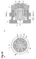
- Fig. 1 is a sectional view illustrating a basic embodiment of a plug 1 in accordance with the present invention.
- Fig. 2 is a plan view illustrating a plug body 2 of the plug depicted in Fig. 1 .
- Fig. 3 is a front view illustrating the plug depicted in Fig. 1 .
- Fig. 4 is a bottom view illustrating the plug depicted in Fig. 1 .
- Fig. 8 is a schematic view illustrating a state where the plug depicted in Fig. 1 is attached to a container body shaped into a bag (pouch).
- the plug 1 is a plug for a container for storing a liquid and has the plug body 2, a lid 3 adapted to engage the plug body, and a columnar elastic body 4 contained in the plug body and pierceable with an extraction needle 30.
- the plug body 2 has an elastic body storage part 5 which is a space for storing the elastic body 4 and a liquid guide path 6 communicating with the elastic body storage part.
- the lid 3 has an elastic body holding part 7 for holding the elastic body 4 and a passage part 8, formed at a center portion of the elastic body holding part, for the extraction needle 30 to pass therethrough.
- the inner wall surface of the plug body 2 facing the elastic body storage part 5 is formed with a plurality of axially extending longitudinal ribs 9.
- axial is meant the axial direction of the elastic body storage part 5 or elastic body 4.
- a plurality of axially extending groove parts 9g are formed between the plurality of longitudinal ribs 9.
- Each longitudinal rib 9 is parallel to the axial direction.
- the inner wall surface of the plug body 2 is provided with eight longitudinal ribs 9 and eight groove parts 9g formed therebetween.
- the plurality of longitudinal ribs 9 are formed at circumferentially equal intervals.
- Each longitudinal rib 9 has a semicircular form in a cross section perpendicular to the axial direction.
- Each longitudinal rib 9 may have other forms in the cross section perpendicular to the axial direction.
- Each longitudinal rib 9 may have a trapezoidal form in the cross section perpendicular to the axial direction, for example.
- the plug body 2 has a taper form at the opening of the elastic storage part 5.
- the longitudinal ribs 9 have the same form.
- the longitudinal ribs 9 radially project from the inner wall surface by the same length (i.e., projection width).
- Each longitudinal rib 9 radially projects from the inner wall surface by an axially fixed length (i.e., projection width).
- a cylinder 9c passing vertexes of the plurality of longitudinal ribs 9 has a diameter smaller than that of the columnar elastic body 4.
- the plurality of longitudinal ribs 9 constructed as explained in the foregoing impart straightness to the needle 30 when it is stuck into the elastic body 4.
- the elastic body 4 is basically a cylindrical column but may be a polygonal column which can exhibit effects similar to those of the cylindrical column.
- the elastic body 4 is stored in the elastic body storage part 5 provided in the plug body 2. For easier insertion into the elastic body storage part 5, it is preferred for the elastic body 4 to round its lower end part (see Fig. 7(a) ).
- the elastic body 4 has a diameter greater than that of the cylinder 9c passing the vertexes of the plurality of longitudinal ribs 9.
- the diameter of the elastic body 4 is greater than that of the cylinder 9c passing the vertexes of the plurality of longitudinal ribs 9 but smaller than that of a cylinder passing the bottom face of the groove parts 9g. This makes it easier to insert the elastic body 4 into the elastic body storage part 5 of the plug body 2.
- the elastic body 4 is inserted downward from the upper part of the elastic body storage part 5 of the plug body 2. At the beginning of insertion, the elastic body 4 has a diameter equal to or slightly greater than that of the inner diameter of the elastic body storage part 5 and thus can easily be inserted therein.
- the elastic body 4 After the leading end part of the elastic body 4 comes into contact with the longitudinal ribs 9 provided on the inner wall surface of the plug body 2, the elastic body 4 is pushed in at once, so as to complete its insertion.
- the lid 3 covering the elastic body 4 from the upper side thereof and the elastic body 4 may be mounted to the plug body 2 at the same time.
- Silicone rubber, ethylene propylene rubber, styrene-based elastomers, polyester-based elastomers, and the like are used typically but not exclusively as materials for the elastic body 4.
- HDPE high-density polyethylene resins
- LDPE low-density polyethylene resins
- L-LDPE linear low-density polyethylene resins
- PP polypropylene resins
- PP polyester-based resins
- vinyl chloride resins vinyl chloride resins
- ABS resins are selected appropriately according to properties of the liquid to be contained.
- the lid 3 functions to hold the elastic body 4 so as to keep it from dropping out.
- the lid 3 has the elastic body holding part 7 for holding the elastic body 4 and the passage part 8, formed at the center portion of the elastic body holding part, for the extraction needle 30 to pass therethrough.
- the passage part 8 is a through hole formed at the center portion of the lid 3.
- the passage part may be formed like a thin plate or membrane instead of the through hole.
- a separate protective component such as a circularly cut aluminum foil, for example, may be mounted on the elastic body 4.
- a method of attaching the lid 3 to the plug body 2 is not limited in particular.
- an engagement protrusion 15 provided on the inner face in the lower end part of the lid 3 engages an engagement groove 14 provided in the plug body 2, so as to be secured.
- the engagement protrusion 15 is shaped into a ring continuous all over the periphery but is not required to be so. It may comprise nail-like structures provided at several locations on the circumference or a pair of threads in threadable engagement with each other provided on the inner periphery of the lid 3 and the outer periphery of a neck part of the plug body 2, respectively.
- the lid 3 attached to the plug body 2 is brought into contact with the plug body 2 under pressure.
- the lid 3 is not brought into contact with the elastic body 4 under pressure. This makes it hard for axial compression stresses to be applied to the elastic body 4.
- the elastic body 4 has a columnar form before being inserted into the elastic body storage part 5. Since the cylinder 9c passing the vertexes of the plurality of longitudinal ribs 9 has a diameter smaller than that of the elastic body 4, a part of the outer periphery of the elastic body 4 comes into contact with the longitudinal ribs 9, so as to be constricted (see Fig. 10(a) ), after the elastic body 4 is inserted into the elastic body storage unit 5. In other words, the elastic body 4 is pressurized by the surfaces of the axially extending longitudinal ribs 9.
- a plurality of gaps 25 are formed between the elastic body 4 stored in the elastic body storage part 5 and the groove parts 9g. Each gap 25 extends axially.
- the elastic body 4 may come into close contact with the longitudinal ribs 9 and groove parts 9g, so as not to form the gaps 25.
- the elastic body 4 may come into close contact with a portion of the groove parts 9g while being separated from the other parts of the longitudinal ribs 9, so as to form small gaps.
- the elastic body 4 is compressed horizontally (i.e., in directions orthogonal to the axial direction) in the constricted part thereof. Therefore, uncompressed and compressed parts 26, 27 are formed in the elastic body 4 so as to be arranged alternately on the circumference of the same circle. In this case, the center of the circle substantially coincides with a center axis L of the elastic body storage part 5.
- the uncompressed part 26 is a part where the compression stress is smaller than a predetermined stress.
- the compressed part 27 is a part where the compression stress is greater than the predetermined stress.
- a plurality of compressed parts 27 are formed in a lower region (region on the liquid guide path 6 side) A of the elastic body 4 surrounded by the plurality of longitudinal ribs 9.
- the plurality of compressed parts 27 are formed at circumferentially equal intervals.
- the compressed parts 27 are formed between the respective longitudinal ribs 9 and the center axis L of the elastic body storage part 5.
- the radial length of the region formed with the compressed parts 27 is about 1/3 to 1/2 of the radius of the elastic body 4.
- each groove part 9g projects radially from the inner wall surface by an axially fixed length.
- the radial length (width) of the compressed parts 27 is axially constant. In other words, they have the same cross-sectional structure in axial cross sections in the lower region A of the elastic body 4.
- a plurality of uncompressed parts 26 are formed between the plurality of compressed parts 27 in the lower region A of the elastic body 4 surrounded by the plurality of longitudinal ribs 9.
- the uncompressed parts 26 are formed between the respective groove parts 9g and the center axis L of the elastic body storage part 5 in the region A. Since the gaps 25 are formed between the elastic body 4 and the groove parts 9g, compression stresses are reduced in directions orthogonal to the axial direction in the uncompressed parts 26.
- a region (region on the passage part 8 side) B above the longitudinal ribs 9 in the elastic body 4 is the uncompressed part 26. In other words, the region other than the compressed parts 27 in the elastic body 4 is the uncompressed part 26.
- the plug 1 has a welding part 12.
- the welding part 12 is a part for attaching the plug body 2 to a container body 20.
- the welding part 12 is shaped like a diamond in a planar view.
- the plug body is securely attached to the container body 20 by welding such that the opening of the bag-shaped container body 20 holds the diamond in the shorter diameter direction.
- the welding part 12 of the plug body 2 is provided with three welding ribs 12r.
- the welding ribs 12r slightly project like lateral streaks from the surface of the welding part 12 and act to prevent the pressure from dispersing when welding the container body 20, so that the welding proceeds securely.
- the lower face of the plug body may be formed with a disk-shaped flange, which is welded to a circular hole opened in the bag-shaped container body.
- the container body and the plug body may be brought into threadable contact with each other by threads or attached to each other as engagement structures by capping.
- a flange 16 illustrated in Figs. 1 to 6 is one for accurately attaching the container body 20 into a case 40 made of a resin.
- the container body 20 having the plug 1 attached thereto is stored in the case 40 having an elongated form.
- the flange 16 of the plug 1 engages one end part 40a of the case 40, whereby the container body 20 is mounted to the case 40, thus completing a cartridge 50.
- the lid 3 and plug body 2 of the plug 1 partly project from one end of the cartridge 50.
- the cartridge 50 is inserted at a predetermined position of a printing device such as a printer.
- the direction in which the cartridge 50 is inserted varies among printers and the like. For example, the cartridge 50 is inserted horizontally.
- the needle 30 fixed within the printer and the like passes through the passage part 8, so as to stick in the elastic body 4.
- the needle 30 When piercing the elastic body 4, the needle 30 at first sticks in the uncompressed part 26 formed in the region B. This makes the needle 30 easy to stick.
- the needle 30 advances through the uncompressed part 26 formed between the plurality of compressed parts 27. Moderate compression stresses act on the uncompressed part 26 in directions orthogonal to the axial direction. Therefore, the needle 30 advances stably. Since the longitudinal ribs 9 apply uniform compressive forces to the compressed parts 27, the compression stresses in the uncompressed part 26 are circumferentially uniform. Since the compression stresses are the lowest at the center axis L, the needle 30 is guided to the center (center axis L).
- the needle 30 is guided so as to approach its normal position. Even when stuck in a region near the compressed part 27 or within the compressed part 27, the needle 30 is not hindered from advancing axially, since the compressed part 27 is a region compressed in directions orthogonal to the axial direction.
- a needle hole E is formed within the region A after the leading end 30a of the needle 30 passed therethrough.
- the needle hole E gradually closes as the needle 30 is pulled.
- Parts of the needle hole E facing the compressed parts 27 radially retract into a concave form in response to radial compression stresses. That is, the elastic body 4 projects radially inward.
- parts of the needle hole E facing the uncompressed parts 26 project radially into a convex form. That is, the elastic body 4 retracts radially outward.
- the needle hole E gradually closes while being formed paraboloidal.
- the needle hole E is formed as a gap between the parts compressed and uncompressed by the longitudinal ribs 9. This gap provides a structure through which the liquid D is easy to return into the container body 20 (i.e., on the liquid guide path 6 side).
- the needle hole E is further reduced while keeping the paraboloidal form mentioned above as illustrated in Figs. 13(a) and 13(b) . That is, the needle hole E is formed as a gap between the parts compressed and uncompressed by the longitudinal ribs 9.
- the gap provides a structure through which the liquid D is easy to return into the container body 20 (i.e., on the liquid guide path 6 side). This paraboloidal structure prevents the needle hole E from closing immediately after the leading end 30a of the needle 30 passes therethrough.
- the needle hole E is closed as illustrated in Fig. 14(a) .
- the liquid D remains only by a very small amount at the tap (one end face of the elastic body 4) as illustrated in Fig. 14(b) .
- the plug 1 is constructed such that the liquid D such as ink is hard to remain within the needle 30 or at the tap.
- the inner wall surface of the plug body 2 facing the elastic body storage part 5 is formed with a plurality of axially extending longitudinal ribs 9.
- the axially extending groove parts 9g are formed between the plurality of longitudinal ribs 9. This makes it easier to insert but harder to compress the elastic body 4 axially. As a result, the needle 30 can easily be inserted in the elastic body 4.
- the diameter of the circle 9c passing the vertexes of the plurality of longitudinal ribs 9 is smaller than that of the columnar elastic body 4. Hence, moderate compression stresses are applied to the elastic body 4 in directions orthogonal to the axial direction. This prevents the liquid splash phenomenon from occurring at the time when the needle 30 is pulled out.
- a plug provided with a cavity serving as a reservoir within an elastic body has conventionally been known. Forming such a cavity in the elastic body makes it hard to shape the elastic body.
- the elastic body it is not necessary for the elastic body to be provided with a cavity serving as a reservoir, whereby the elastic body 4 is easy to shape.
- the needle hole E which is naturally formed by the needle 30, can be used so that the liquid D flows therethrough to the container body 20. No liquid will leak even when the needle 30 is repeatedly stuck in and pulled out.
- the plurality of longitudinal ribs 9 project radially from the inner wall surface by an axially fixed length, whereby compression stresses applied to the elastic body 4 in directions orthogonal to the axial direction are substantially constant in the axial direction. Therefore, the needle 30 receives substantially constant compression stresses from the elastic body even when changing its position. Hence, the needle 30 can smoothly be guided axially without bending.
- the axially extending gap 25 is formed between the elastic body 4 and the groove part 9g, so as to reduce the compression stress axially applied to the elastic body 4 in a region between the gap 25 and the axis of the elastic body 4, i.e., the uncompressed part 26. Hence, the needle 30 can be inserted more smoothly.
- the longitudinal rib 9 has a semicircular form in a cross section perpendicular to the axial direction, while the plug body 2 has a taper form at an opening of the elastic body storage part 5, the elastic body 4 can be inserted easily.
- the columnar elastic body 4 When being inserted into the elastic body storage part 5 of the plug body 2, the columnar elastic body 4 has substantially the same diameter at the beginning of insertion and thus is easy to insert.
- the elastic body 4 can easily be inserted by axial press fitting alone after the leading end of the elastic body 4 comes into contact with the longitudinal ribs 9 on the inner wall surface of the storage part 5, whereby the plug 1 can be assembled simply.
- the elastic body 4 Since the diameter of the columnar elastic body 4 is greater than that of the cylinder 9c passing the vertexes of the plurality of longitudinal ribs 9 but smaller than that of a cylinder passing the bottom face of the groove parts 9g, the elastic body 4 can be inserted more easily in the elastic body storage part 5. Also, the pressurizing effect on the elastic body 4 can fully be expected.
- the plug body 2 has the welding part 12 for welding the container body 20
- a bag-shaped container can be chosen as the container body 20, thus developing various uses.
- the lid 3 has, on the inner face in the lower end part thereof, the engagement protrusion 15 adapted to engage the engagement groove 14 provided in the plug body 2, a simple operation of just press-fitting the lid 3 into the plug body 2 from thereabove can assemble the plug 1 in the process of assembling the plug 1.
- Fig. 5 is a sectional view illustrating another embodiment of the plug 1 in accordance with the present invention.
- Fig. 6 is a plan view illustrating the plug body 2 of the plug 1 depicted in Fig. 5 as seen from thereabove.
- Figs. 7(a) and 7(b) are schematic views illustrating the elastic body 4 of the plug 1 depicted in Fig. 5 as seen sideways and from thereabove, respectively.
- the columnar elastic body 4 has a collar 13 in its head part.
- a comer of a shoulder of the collar 13 is formed with a chamfer 13c.
- the passage part 8 of the lid 3 is covered with a thin protection plate 10.
- a thin sealing plate 11 is provided between the elastic body storage part 5 and liquid guide path 6 of the plug body 2. Except for these points, this embodiment is basically the same as the embodiment illustrated in Fig. 1 .
- the elastic body 4 Since the elastic body 4 has the collar 13, which comes into close contact with the upper face of the plug body 2, the sealing performance of the container body 20 becomes higher. While the collar 13 is axially compressed as being held between the upper face of the plug body 2 and the lid 3, the influence thereof fails short of reaching the center part of the elastic body 4 and thus will not adversely affect the sticking and pulling of the extraction needle.
- the elastic body 4 can easily be inserted in the plug body 2. Further, the lid 3 can easily be mounted to the plug body 2. This also prevents the liquid from leaking.
- the elastic body 4 Since the passage part 8 of the lid 3 is provided with the protection plate 10, the elastic body 4 is not exposed to the outside, which can prevent dust from accumulating on the upper face of the elastic body 4 and so forth.
- the protection plate 10 is so thin that it does not hinder the extraction needle 30 from piercing. The protection plate 10 remaining intact proves that the package is unopened.
- the thin sealing plate 11 is provided between the elastic body storage part 5 and liquid guide path 6 of the plug body 2, when the container body 20 is unused, the liquid contained therein and the elastic body 4 can be prevented from coming into direct contact with each other. This can keep the liquid from coming into contact with the elastic body 4 for a long period of time and being adversely affected thereby and the elastic body 4 from deteriorating while in contact with the liquid.
- the sealing plate 11 is also so thin that it does not hinder the extraction needle 30 from piercing.
- the periphery of the container body 20 is partly left unsealed in the example illustrated in Fig. 8 , so as to feed the liquid D therefrom, and is finally sealed thereafter.
- the plug 1 of the above-mentioned embodiment is easy to assemble because of its simple structure, exhibits favorable basic usability such as easiness for the needle 30 to pierce, and is less likely to leak liquids. It also has an excellent merit that no liquid splash occurs when pulling out the needle 30 and so forth.
- the plug 1 can favorably be used as a plug for containers for storing various liquids.
- the plug of the present invention is not limited to the above-mentioned embodiments.
- the length by which the plurality of longitudinal ribs 9 project radially from the inner wall surface may vary axially. That is, the longitudinal ribs 9 may have a taper form somewhat tilting axially.
- the numbers of the longitudinal ribs 9 and groove parts 9g are not limited in particular. The number or projection width of the longitudinal ribs 9 may be changed according to the form, material, or size of the elastic body 4 to be held.
- the plug in accordance with one aspect of the present invention allows a needle to be inserted easily therein and can prevent the liquid splash phenomenon from occurring when pulling out the needle.
Landscapes
- Engineering & Computer Science (AREA)
- Mechanical Engineering (AREA)
- Closures For Containers (AREA)
- Bag Frames (AREA)
- Packages (AREA)
Applications Claiming Priority (2)
| Application Number | Priority Date | Filing Date | Title |
|---|---|---|---|
| JP2011281428 | 2011-12-22 | ||
| PCT/JP2012/082811 WO2013094611A1 (ja) | 2011-12-22 | 2012-12-18 | 口栓 |
Publications (3)
| Publication Number | Publication Date |
|---|---|
| EP2796383A1 true EP2796383A1 (de) | 2014-10-29 |
| EP2796383A4 EP2796383A4 (de) | 2015-10-28 |
| EP2796383B1 EP2796383B1 (de) | 2018-06-20 |
Family
ID=48668498
Family Applications (1)
| Application Number | Title | Priority Date | Filing Date |
|---|---|---|---|
| EP12860996.3A Active EP2796383B1 (de) | 2011-12-22 | 2012-12-18 | Stopfen |
Country Status (8)
| Country | Link |
|---|---|
| US (1) | US9656786B2 (de) |
| EP (1) | EP2796383B1 (de) |
| JP (1) | JP6256004B2 (de) |
| CN (1) | CN104010945B (de) |
| ES (1) | ES2680669T3 (de) |
| PT (1) | PT2796383T (de) |
| TW (1) | TWI590996B (de) |
| WO (1) | WO2013094611A1 (de) |
Cited By (4)
| Publication number | Priority date | Publication date | Assignee | Title |
|---|---|---|---|---|
| WO2017178351A1 (de) * | 2016-04-12 | 2017-10-19 | Ebs Ink Jet Systeme Gmbh | Flüssigkeitskartusche und auf ein verfahren zum füllen einer derartigen kartusche mit einer flüssigkeit |
| EP3725532A1 (de) * | 2019-04-18 | 2020-10-21 | Taiwan Nanotechnolog Corporation | Verbinderstruktur eines tintenbeutels |
| WO2021001827A1 (en) * | 2019-07-04 | 2021-01-07 | Stratasys Ltd. | Method and system for monitoring amount of supply material in additive manufacturing |
| USD949962S1 (en) | 2019-07-04 | 2022-04-26 | Stratasys Ltd. | Cartridge for 3D printing |
Families Citing this family (12)
| Publication number | Priority date | Publication date | Assignee | Title |
|---|---|---|---|---|
| US8887369B2 (en) * | 2011-12-09 | 2014-11-18 | The Gillette Company | Personal-care appliance and method of assembly |
| JP6458544B2 (ja) * | 2015-02-24 | 2019-01-30 | 凸版印刷株式会社 | 口栓 |
| JP6950146B2 (ja) * | 2016-02-26 | 2021-10-13 | 凸版印刷株式会社 | 口栓 |
| JP6983506B2 (ja) * | 2016-12-20 | 2021-12-17 | ニプロ株式会社 | 医療用スパウト、及びそれを備える医療用バッグ |
| US11198299B2 (en) * | 2018-07-13 | 2021-12-14 | Hewlett-Packard Development Company, L.P. | Collar for fluid barrier |
| WO2020013849A1 (en) | 2018-07-13 | 2020-01-16 | Hewlett-Packard Development Company, L.P. | Clamp plates with wedge-shaped fork ends for a print liquid supply |
| EP4129699A1 (de) * | 2018-07-13 | 2023-02-08 | Hewlett-Packard Development Company L.P. | Tüllen mit abgewinkelten klemmflanschen für eine druckflüssigkeitszufuhr |
| EP3687810B1 (de) | 2018-07-13 | 2023-04-12 | Hewlett-Packard Development Company, L.P. | Biegsame druckflüssigkeitszufuhrbehälter mit versetzter tülle |
| WO2020013839A1 (en) | 2018-07-13 | 2020-01-16 | Hewlett-Packard Development Company, L.P. | Coupling systems |
| CN110217481B (zh) * | 2019-05-09 | 2023-06-13 | 复旦大学附属中山医院 | 一种收集管管盖 |
| CN110386456B (zh) * | 2019-08-26 | 2024-05-03 | 南京工程学院 | 基于柔性制造末端50kg抓取机构 |
| JP7250660B2 (ja) * | 2019-10-31 | 2023-04-03 | 株式会社吉野工業所 | 注出キャップ |
Family Cites Families (32)
| Publication number | Priority date | Publication date | Assignee | Title |
|---|---|---|---|---|
| US2906423A (en) | 1956-07-18 | 1959-09-29 | American Cyanamid Co | Closure puncturable by polyethylene needle |
| BE755165A (fr) * | 1969-08-23 | 1971-02-22 | Philips Nv | Bouchon elastiquement deformable pour seringue d'injection |
| SE388178B (sv) * | 1974-09-06 | 1976-09-27 | Pharmacia Ab | Tetande forslutning for behallare |
| DE3345619A1 (de) * | 1983-12-16 | 1985-06-20 | Günter 7519 Eppingen Grittmann | Spundlochverschluss fuer dosen |
| AT380392B (de) * | 1985-01-24 | 1986-05-12 | C A Greiner & S Hne Ges M B H | Blutprobenr!hrchen |
| US4967919A (en) * | 1988-11-23 | 1990-11-06 | Sherwood Medical Company | Blood collection tube safety cap |
| US5088995A (en) * | 1990-06-22 | 1992-02-18 | Baxter International Inc. | Port and closure assembly including a resealing injection site for a container |
| US5199948A (en) * | 1991-05-02 | 1993-04-06 | Mcgaw, Inc. | Needleless valve |
| US5494170A (en) * | 1993-05-06 | 1996-02-27 | Becton Dickinson And Company | Combination stopper-shield closure |
| JPH085503B2 (ja) | 1993-07-13 | 1996-01-24 | 日本キム株式会社 | スパウト |
| DE4341047A1 (de) | 1993-12-02 | 1995-06-08 | Freudenberg Carl Fa | Infusionsflasche |
| JP2706632B2 (ja) | 1995-04-13 | 1998-01-28 | 日本キム株式会社 | スパウト |
| JP3634944B2 (ja) * | 1997-06-18 | 2005-03-30 | 内外化成株式会社 | 医療用キャップ |
| JP4477216B2 (ja) * | 2000-10-26 | 2010-06-09 | 株式会社大塚製薬工場 | キャップとその製造方法およびそれを用いた薬剤容器 |
| EP1990092B1 (de) * | 2001-03-09 | 2010-02-10 | Gen-Probe Incorporated | Durchlässige Haube |
| JP2002326644A (ja) | 2001-04-27 | 2002-11-12 | Nissui Pharm Co Ltd | キャップ |
| US6550493B2 (en) * | 2001-06-13 | 2003-04-22 | Baxter International Inc. | Vacuum demand valve |
| JP2003169840A (ja) | 2001-12-07 | 2003-06-17 | Otsuka Pharmaceut Factory Inc | キャップおよびそれを備える薬液容器 |
| ITVI20020131A1 (it) * | 2002-06-17 | 2003-12-17 | Vacutest Kima Srl | Tappo con protezione per provette |
| JP2004065459A (ja) | 2002-08-05 | 2004-03-04 | Otsuka Pharmaceut Factory Inc | キャップおよびそれを用いた医療用容器 |
| AU2003254926A1 (en) * | 2002-08-12 | 2004-03-19 | Jms Co., Ltd. | Needle-less port and method of producing the same |
| JP4292832B2 (ja) * | 2003-03-11 | 2009-07-08 | ブラザー工業株式会社 | インクパッケージ |
| US7185975B2 (en) | 2003-03-11 | 2007-03-06 | Brother Kogyo Kabushiki Kaisha | Ink detecting apparatus and ink package |
| DE10313760B3 (de) * | 2003-03-27 | 2004-06-03 | Fresenius Kabi Deutschland Gmbh | Konnektor für medizinische Flüssigkeiten enthaltende Verpackungen und Verpackung für medizinische Flüssigkeiten |
| JP4060247B2 (ja) | 2003-07-14 | 2008-03-12 | 株式会社大塚製薬工場 | 薬剤容器用の口部材 |
| JP2005073839A (ja) * | 2003-08-29 | 2005-03-24 | Naigai Kasei Kk | 医療用キャップ |
| DE10348016B4 (de) * | 2003-10-15 | 2007-05-03 | Fresenius Kabi Deutschland Gmbh | Konnektor für medizinische Flüssigkeiten enthaltende Verpackungen und Verpackung für medizinische Flüssigkeiten |
| AU2003292387B2 (en) * | 2003-12-05 | 2009-11-26 | American Flange And Mfg Co Inc | Closure plug and overseal |
| JP2006341914A (ja) | 2005-06-10 | 2006-12-21 | Nippon Kimu Kk | スパウト |
| JP5231794B2 (ja) * | 2007-12-10 | 2013-07-10 | 株式会社大協精工 | バイアル用プラスチック製キャップ |
| CN201592827U (zh) * | 2010-01-11 | 2010-09-29 | 栓乐多瓶塞有限公司 | 外盖式瓶塞 |
| TWI440585B (zh) | 2010-03-02 | 2014-06-11 | Sunlot Bottle Strpper Co Ltd | 二件式瓶塞 |
-
2012
- 2012-12-18 WO PCT/JP2012/082811 patent/WO2013094611A1/ja active Application Filing
- 2012-12-18 PT PT128609963T patent/PT2796383T/pt unknown
- 2012-12-18 EP EP12860996.3A patent/EP2796383B1/de active Active
- 2012-12-18 ES ES12860996.3T patent/ES2680669T3/es active Active
- 2012-12-18 CN CN201280063349.9A patent/CN104010945B/zh active Active
- 2012-12-18 JP JP2013550291A patent/JP6256004B2/ja active Active
- 2012-12-18 US US14/367,652 patent/US9656786B2/en active Active
- 2012-12-21 TW TW101148889A patent/TWI590996B/zh active
Cited By (5)
| Publication number | Priority date | Publication date | Assignee | Title |
|---|---|---|---|---|
| WO2017178351A1 (de) * | 2016-04-12 | 2017-10-19 | Ebs Ink Jet Systeme Gmbh | Flüssigkeitskartusche und auf ein verfahren zum füllen einer derartigen kartusche mit einer flüssigkeit |
| US10507664B2 (en) | 2016-04-12 | 2019-12-17 | Ebs Ink Jet Systeme Gmbh | Liquid cartridge, and a method for filling a cartridge of this type with a liquid |
| EP3725532A1 (de) * | 2019-04-18 | 2020-10-21 | Taiwan Nanotechnolog Corporation | Verbinderstruktur eines tintenbeutels |
| WO2021001827A1 (en) * | 2019-07-04 | 2021-01-07 | Stratasys Ltd. | Method and system for monitoring amount of supply material in additive manufacturing |
| USD949962S1 (en) | 2019-07-04 | 2022-04-26 | Stratasys Ltd. | Cartridge for 3D printing |
Also Published As
| Publication number | Publication date |
|---|---|
| ES2680669T3 (es) | 2018-09-10 |
| TWI590996B (zh) | 2017-07-11 |
| US9656786B2 (en) | 2017-05-23 |
| CN104010945A (zh) | 2014-08-27 |
| JP6256004B2 (ja) | 2018-01-10 |
| US20140332492A1 (en) | 2014-11-13 |
| PT2796383T (pt) | 2018-06-28 |
| JPWO2013094611A1 (ja) | 2015-04-27 |
| EP2796383A4 (de) | 2015-10-28 |
| EP2796383B1 (de) | 2018-06-20 |
| TW201332856A (zh) | 2013-08-16 |
| WO2013094611A1 (ja) | 2013-06-27 |
| CN104010945B (zh) | 2019-01-01 |
Similar Documents
| Publication | Publication Date | Title |
|---|---|---|
| EP2796383B1 (de) | Stopfen | |
| US8020728B2 (en) | Container and method for opening a container | |
| EP2724789B1 (de) | Flüssigkeitsabgabevorrichtungen und Verfahren zur Abgabe von Flüssigkeiten aus Behältern | |
| EP2694396B1 (de) | Kappe mit zusatzstoffkammer und zugehörige verpackungseinheit | |
| JP5204117B2 (ja) | 蓋及び分注システム | |
| US20120175384A1 (en) | Sealed container comprising a displaceable piston | |
| IL101571A (en) | Needle for a retractable syringe | |
| JP2009527420A (ja) | フィルム・バッグを穿孔するための装置 | |
| US10639464B2 (en) | Discharger | |
| MX2013004042A (es) | Cierre de plástico que tiene una cápsula para surtir ingredientes activos. | |
| CN110914173A (zh) | 包括用于包装第二流体的囊状物的用于包装第一流体的容器和适用于所述容器的囊状物 | |
| EP1771349B1 (de) | Applikator für fluide substanzen für den einsatz in der medizin und/oder kosmetik | |
| JP5929120B2 (ja) | 口栓 | |
| KR20190133662A (ko) | 액체 재료 저류 용기용 덮개 및 액체 재료 저류 용기 | |
| EP3521192B1 (de) | Verpackungssystem aufweisend eine ausgabevorrichtung und eine spendekappe | |
| US6726060B1 (en) | Threaded closure for tube opening | |
| US9642774B2 (en) | Liquid container with predetermined breaking point | |
| WO2019226145A1 (en) | Dispensable substance containers | |
| US11858696B2 (en) | Dispensing nozzles | |
| JP2007055620A (ja) | スパウト | |
| JP5309307B2 (ja) | 開封具 | |
| KR20130119820A (ko) | 내용물 보존 밀림식 점성물질 포장용기 | |
| JP2018013428A (ja) | 定量送液検査キット | |
| WO2008075698A1 (ja) | 閉蓋具および液体材料貯留容器 | |
| KR20120041712A (ko) | 일회용 포장용기 |
Legal Events
| Date | Code | Title | Description |
|---|---|---|---|
| PUAI | Public reference made under article 153(3) epc to a published international application that has entered the european phase |
Free format text: ORIGINAL CODE: 0009012 |
|
| 17P | Request for examination filed |
Effective date: 20140625 |
|
| AK | Designated contracting states |
Kind code of ref document: A1 Designated state(s): AL AT BE BG CH CY CZ DE DK EE ES FI FR GB GR HR HU IE IS IT LI LT LU LV MC MK MT NL NO PL PT RO RS SE SI SK SM TR |
|
| DAX | Request for extension of the european patent (deleted) | ||
| RA4 | Supplementary search report drawn up and despatched (corrected) |
Effective date: 20150924 |
|
| RIC1 | Information provided on ipc code assigned before grant |
Ipc: B65D 75/58 20060101ALI20150918BHEP Ipc: B65D 51/18 20060101AFI20150918BHEP Ipc: B65D 51/20 20060101ALI20150918BHEP |
|
| REG | Reference to a national code |
Ref country code: DE Ref legal event code: R079 Ref document number: 602012047739 Country of ref document: DE Free format text: PREVIOUS MAIN CLASS: B65D0051180000 Ipc: B65D0051000000 |
|
| GRAP | Despatch of communication of intention to grant a patent |
Free format text: ORIGINAL CODE: EPIDOSNIGR1 |
|
| RIC1 | Information provided on ipc code assigned before grant |
Ipc: B65D 75/58 20060101ALI20171201BHEP Ipc: A61J 1/14 20060101ALI20171201BHEP Ipc: B41J 2/175 20060101ALI20171201BHEP Ipc: B65D 51/00 20060101AFI20171201BHEP |
|
| INTG | Intention to grant announced |
Effective date: 20180108 |
|
| GRAS | Grant fee paid |
Free format text: ORIGINAL CODE: EPIDOSNIGR3 |
|
| GRAA | (expected) grant |
Free format text: ORIGINAL CODE: 0009210 |
|
| AK | Designated contracting states |
Kind code of ref document: B1 Designated state(s): AL AT BE BG CH CY CZ DE DK EE ES FI FR GB GR HR HU IE IS IT LI LT LU LV MC MK MT NL NO PL PT RO RS SE SI SK SM TR |
|
| REG | Reference to a national code |
Ref country code: GB Ref legal event code: FG4D |
|
| REG | Reference to a national code |
Ref country code: PT Ref legal event code: SC4A Ref document number: 2796383 Country of ref document: PT Date of ref document: 20180628 Kind code of ref document: T Free format text: AVAILABILITY OF NATIONAL TRANSLATION Effective date: 20180620 |
|
| REG | Reference to a national code |
Ref country code: IE Ref legal event code: FG4D |
|
| REG | Reference to a national code |
Ref country code: AT Ref legal event code: REF Ref document number: 1010424 Country of ref document: AT Kind code of ref document: T Effective date: 20180715 |
|
| REG | Reference to a national code |
Ref country code: NL Ref legal event code: FP |
|
| REG | Reference to a national code |
Ref country code: DE Ref legal event code: R096 Ref document number: 602012047739 Country of ref document: DE |
|
| REG | Reference to a national code |
Ref country code: LT Ref legal event code: MG4D |
|
| REG | Reference to a national code |
Ref country code: ES Ref legal event code: FG2A Ref document number: 2680669 Country of ref document: ES Kind code of ref document: T3 Effective date: 20180910 |
|
| PG25 | Lapsed in a contracting state [announced via postgrant information from national office to epo] |
Ref country code: SE Free format text: LAPSE BECAUSE OF FAILURE TO SUBMIT A TRANSLATION OF THE DESCRIPTION OR TO PAY THE FEE WITHIN THE PRESCRIBED TIME-LIMIT Effective date: 20180620 Ref country code: FI Free format text: LAPSE BECAUSE OF FAILURE TO SUBMIT A TRANSLATION OF THE DESCRIPTION OR TO PAY THE FEE WITHIN THE PRESCRIBED TIME-LIMIT Effective date: 20180620 Ref country code: BG Free format text: LAPSE BECAUSE OF FAILURE TO SUBMIT A TRANSLATION OF THE DESCRIPTION OR TO PAY THE FEE WITHIN THE PRESCRIBED TIME-LIMIT Effective date: 20180920 Ref country code: NO Free format text: LAPSE BECAUSE OF FAILURE TO SUBMIT A TRANSLATION OF THE DESCRIPTION OR TO PAY THE FEE WITHIN THE PRESCRIBED TIME-LIMIT Effective date: 20180920 Ref country code: LT Free format text: LAPSE BECAUSE OF FAILURE TO SUBMIT A TRANSLATION OF THE DESCRIPTION OR TO PAY THE FEE WITHIN THE PRESCRIBED TIME-LIMIT Effective date: 20180620 |
|
| PG25 | Lapsed in a contracting state [announced via postgrant information from national office to epo] |
Ref country code: RS Free format text: LAPSE BECAUSE OF FAILURE TO SUBMIT A TRANSLATION OF THE DESCRIPTION OR TO PAY THE FEE WITHIN THE PRESCRIBED TIME-LIMIT Effective date: 20180620 Ref country code: HR Free format text: LAPSE BECAUSE OF FAILURE TO SUBMIT A TRANSLATION OF THE DESCRIPTION OR TO PAY THE FEE WITHIN THE PRESCRIBED TIME-LIMIT Effective date: 20180620 Ref country code: GR Free format text: LAPSE BECAUSE OF FAILURE TO SUBMIT A TRANSLATION OF THE DESCRIPTION OR TO PAY THE FEE WITHIN THE PRESCRIBED TIME-LIMIT Effective date: 20180921 |
|
| REG | Reference to a national code |
Ref country code: AT Ref legal event code: MK05 Ref document number: 1010424 Country of ref document: AT Kind code of ref document: T Effective date: 20180620 |
|
| PG25 | Lapsed in a contracting state [announced via postgrant information from national office to epo] |
Ref country code: CZ Free format text: LAPSE BECAUSE OF FAILURE TO SUBMIT A TRANSLATION OF THE DESCRIPTION OR TO PAY THE FEE WITHIN THE PRESCRIBED TIME-LIMIT Effective date: 20180620 Ref country code: RO Free format text: LAPSE BECAUSE OF FAILURE TO SUBMIT A TRANSLATION OF THE DESCRIPTION OR TO PAY THE FEE WITHIN THE PRESCRIBED TIME-LIMIT Effective date: 20180620 Ref country code: SK Free format text: LAPSE BECAUSE OF FAILURE TO SUBMIT A TRANSLATION OF THE DESCRIPTION OR TO PAY THE FEE WITHIN THE PRESCRIBED TIME-LIMIT Effective date: 20180620 Ref country code: AT Free format text: LAPSE BECAUSE OF FAILURE TO SUBMIT A TRANSLATION OF THE DESCRIPTION OR TO PAY THE FEE WITHIN THE PRESCRIBED TIME-LIMIT Effective date: 20180620 Ref country code: PL Free format text: LAPSE BECAUSE OF FAILURE TO SUBMIT A TRANSLATION OF THE DESCRIPTION OR TO PAY THE FEE WITHIN THE PRESCRIBED TIME-LIMIT Effective date: 20180620 Ref country code: IS Free format text: LAPSE BECAUSE OF FAILURE TO SUBMIT A TRANSLATION OF THE DESCRIPTION OR TO PAY THE FEE WITHIN THE PRESCRIBED TIME-LIMIT Effective date: 20181020 Ref country code: EE Free format text: LAPSE BECAUSE OF FAILURE TO SUBMIT A TRANSLATION OF THE DESCRIPTION OR TO PAY THE FEE WITHIN THE PRESCRIBED TIME-LIMIT Effective date: 20180620 |
|
| PG25 | Lapsed in a contracting state [announced via postgrant information from national office to epo] |
Ref country code: SI Free format text: LAPSE BECAUSE OF FAILURE TO SUBMIT A TRANSLATION OF THE DESCRIPTION OR TO PAY THE FEE WITHIN THE PRESCRIBED TIME-LIMIT Effective date: 20180620 Ref country code: IT Free format text: LAPSE BECAUSE OF FAILURE TO SUBMIT A TRANSLATION OF THE DESCRIPTION OR TO PAY THE FEE WITHIN THE PRESCRIBED TIME-LIMIT Effective date: 20180620 Ref country code: SM Free format text: LAPSE BECAUSE OF FAILURE TO SUBMIT A TRANSLATION OF THE DESCRIPTION OR TO PAY THE FEE WITHIN THE PRESCRIBED TIME-LIMIT Effective date: 20180620 |
|
| REG | Reference to a national code |
Ref country code: DE Ref legal event code: R097 Ref document number: 602012047739 Country of ref document: DE |
|
| PLBE | No opposition filed within time limit |
Free format text: ORIGINAL CODE: 0009261 |
|
| STAA | Information on the status of an ep patent application or granted ep patent |
Free format text: STATUS: NO OPPOSITION FILED WITHIN TIME LIMIT |
|
| 26N | No opposition filed |
Effective date: 20190321 |
|
| PG25 | Lapsed in a contracting state [announced via postgrant information from national office to epo] |
Ref country code: DK Free format text: LAPSE BECAUSE OF FAILURE TO SUBMIT A TRANSLATION OF THE DESCRIPTION OR TO PAY THE FEE WITHIN THE PRESCRIBED TIME-LIMIT Effective date: 20180620 |
|
| REG | Reference to a national code |
Ref country code: CH Ref legal event code: PL |
|
| REG | Reference to a national code |
Ref country code: NL Ref legal event code: MM Effective date: 20190101 |
|
| GBPC | Gb: european patent ceased through non-payment of renewal fee |
Effective date: 20181218 |
|
| PG25 | Lapsed in a contracting state [announced via postgrant information from national office to epo] |
Ref country code: LU Free format text: LAPSE BECAUSE OF NON-PAYMENT OF DUE FEES Effective date: 20181218 Ref country code: LV Free format text: LAPSE BECAUSE OF NON-PAYMENT OF DUE FEES Effective date: 20181218 Ref country code: MC Free format text: LAPSE BECAUSE OF FAILURE TO SUBMIT A TRANSLATION OF THE DESCRIPTION OR TO PAY THE FEE WITHIN THE PRESCRIBED TIME-LIMIT Effective date: 20180620 |
|
| REG | Reference to a national code |
Ref country code: IE Ref legal event code: MM4A |
|
| PG25 | Lapsed in a contracting state [announced via postgrant information from national office to epo] |
Ref country code: NL Free format text: LAPSE BECAUSE OF NON-PAYMENT OF DUE FEES Effective date: 20190101 |
|
| REG | Reference to a national code |
Ref country code: BE Ref legal event code: MM Effective date: 20181231 |
|
| PG25 | Lapsed in a contracting state [announced via postgrant information from national office to epo] |
Ref country code: PT Free format text: LAPSE BECAUSE OF NON-PAYMENT OF DUE FEES Effective date: 20190918 Ref country code: FR Free format text: LAPSE BECAUSE OF NON-PAYMENT OF DUE FEES Effective date: 20181231 Ref country code: IE Free format text: LAPSE BECAUSE OF NON-PAYMENT OF DUE FEES Effective date: 20181218 |
|
| PG25 | Lapsed in a contracting state [announced via postgrant information from national office to epo] |
Ref country code: AL Free format text: LAPSE BECAUSE OF FAILURE TO SUBMIT A TRANSLATION OF THE DESCRIPTION OR TO PAY THE FEE WITHIN THE PRESCRIBED TIME-LIMIT Effective date: 20180620 Ref country code: BE Free format text: LAPSE BECAUSE OF NON-PAYMENT OF DUE FEES Effective date: 20181231 |
|
| PG25 | Lapsed in a contracting state [announced via postgrant information from national office to epo] |
Ref country code: CH Free format text: LAPSE BECAUSE OF NON-PAYMENT OF DUE FEES Effective date: 20181231 Ref country code: LI Free format text: LAPSE BECAUSE OF NON-PAYMENT OF DUE FEES Effective date: 20181231 Ref country code: GB Free format text: LAPSE BECAUSE OF NON-PAYMENT OF DUE FEES Effective date: 20181218 |
|
| PG25 | Lapsed in a contracting state [announced via postgrant information from national office to epo] |
Ref country code: MT Free format text: LAPSE BECAUSE OF NON-PAYMENT OF DUE FEES Effective date: 20181218 |
|
| REG | Reference to a national code |
Ref country code: ES Ref legal event code: FD2A Effective date: 20200203 |
|
| PG25 | Lapsed in a contracting state [announced via postgrant information from national office to epo] |
Ref country code: TR Free format text: LAPSE BECAUSE OF FAILURE TO SUBMIT A TRANSLATION OF THE DESCRIPTION OR TO PAY THE FEE WITHIN THE PRESCRIBED TIME-LIMIT Effective date: 20180620 |
|
| PG25 | Lapsed in a contracting state [announced via postgrant information from national office to epo] |
Ref country code: ES Free format text: LAPSE BECAUSE OF NON-PAYMENT OF DUE FEES Effective date: 20181219 |
|
| PG25 | Lapsed in a contracting state [announced via postgrant information from national office to epo] |
Ref country code: HU Free format text: LAPSE BECAUSE OF FAILURE TO SUBMIT A TRANSLATION OF THE DESCRIPTION OR TO PAY THE FEE WITHIN THE PRESCRIBED TIME-LIMIT; INVALID AB INITIO Effective date: 20121218 Ref country code: CY Free format text: LAPSE BECAUSE OF FAILURE TO SUBMIT A TRANSLATION OF THE DESCRIPTION OR TO PAY THE FEE WITHIN THE PRESCRIBED TIME-LIMIT Effective date: 20180620 |
|
| P01 | Opt-out of the competence of the unified patent court (upc) registered |
Effective date: 20230530 |
|
| PGFP | Annual fee paid to national office [announced via postgrant information from national office to epo] |
Ref country code: DE Payment date: 20231031 Year of fee payment: 12 |