EP2778034A2 - Automatisches System zur Speicherung von Zyklen, Zyklus für ein solches System und Aufnahmestruktur für einen solchen Zyklus - Google Patents
Automatisches System zur Speicherung von Zyklen, Zyklus für ein solches System und Aufnahmestruktur für einen solchen Zyklus Download PDFInfo
- Publication number
- EP2778034A2 EP2778034A2 EP20140166519 EP14166519A EP2778034A2 EP 2778034 A2 EP2778034 A2 EP 2778034A2 EP 20140166519 EP20140166519 EP 20140166519 EP 14166519 A EP14166519 A EP 14166519A EP 2778034 A2 EP2778034 A2 EP 2778034A2
- Authority
- EP
- European Patent Office
- Prior art keywords
- cycle
- locking member
- locking
- lock
- latch
- Prior art date
- Legal status (The legal status is an assumption and is not a legal conclusion. Google has not performed a legal analysis and makes no representation as to the accuracy of the status listed.)
- Withdrawn
Links
- 238000003032 molecular docking Methods 0.000 abstract 7
- 238000004891 communication Methods 0.000 description 12
- 230000002452 interceptive effect Effects 0.000 description 12
- 239000002184 metal Substances 0.000 description 10
- 208000031968 Cadaver Diseases 0.000 description 4
- 238000013475 authorization Methods 0.000 description 3
- 238000010586 diagram Methods 0.000 description 3
- 238000004146 energy storage Methods 0.000 description 3
- 239000011159 matrix material Substances 0.000 description 3
- 241001080024 Telles Species 0.000 description 2
- 238000012550 audit Methods 0.000 description 2
- 230000005540 biological transmission Effects 0.000 description 2
- 239000004020 conductor Substances 0.000 description 2
- 238000009434 installation Methods 0.000 description 2
- 239000002699 waste material Substances 0.000 description 2
- 238000004804 winding Methods 0.000 description 2
- 241000287107 Passer Species 0.000 description 1
- 240000008042 Zea mays Species 0.000 description 1
- 230000000903 blocking effect Effects 0.000 description 1
- 239000000470 constituent Substances 0.000 description 1
- 230000001351 cycling effect Effects 0.000 description 1
- 230000006866 deterioration Effects 0.000 description 1
- 238000007599 discharging Methods 0.000 description 1
- 239000012777 electrically insulating material Substances 0.000 description 1
- 238000001914 filtration Methods 0.000 description 1
- 238000003780 insertion Methods 0.000 description 1
- 230000037431 insertion Effects 0.000 description 1
- 239000011810 insulating material Substances 0.000 description 1
- 239000000463 material Substances 0.000 description 1
- 210000000056 organ Anatomy 0.000 description 1
- 230000000284 resting effect Effects 0.000 description 1
- XLYOFNOQVPJJNP-UHFFFAOYSA-N water Substances O XLYOFNOQVPJJNP-UHFFFAOYSA-N 0.000 description 1
Images


Classifications
-
- B—PERFORMING OPERATIONS; TRANSPORTING
- B62—LAND VEHICLES FOR TRAVELLING OTHERWISE THAN ON RAILS
- B62M—RIDER PROPULSION OF WHEELED VEHICLES OR SLEDGES; POWERED PROPULSION OF SLEDGES OR SINGLE-TRACK CYCLES; TRANSMISSIONS SPECIALLY ADAPTED FOR SUCH VEHICLES
- B62M6/00—Rider propulsion of wheeled vehicles with additional source of power, e.g. combustion engine or electric motor
- B62M6/40—Rider propelled cycles with auxiliary electric motor
-
- B—PERFORMING OPERATIONS; TRANSPORTING
- B60—VEHICLES IN GENERAL
- B60L—PROPULSION OF ELECTRICALLY-PROPELLED VEHICLES; SUPPLYING ELECTRIC POWER FOR AUXILIARY EQUIPMENT OF ELECTRICALLY-PROPELLED VEHICLES; ELECTRODYNAMIC BRAKE SYSTEMS FOR VEHICLES IN GENERAL; MAGNETIC SUSPENSION OR LEVITATION FOR VEHICLES; MONITORING OPERATING VARIABLES OF ELECTRICALLY-PROPELLED VEHICLES; ELECTRIC SAFETY DEVICES FOR ELECTRICALLY-PROPELLED VEHICLES
- B60L50/00—Electric propulsion with power supplied within the vehicle
- B60L50/20—Electric propulsion with power supplied within the vehicle using propulsion power generated by humans or animals
-
- B—PERFORMING OPERATIONS; TRANSPORTING
- B60—VEHICLES IN GENERAL
- B60L—PROPULSION OF ELECTRICALLY-PROPELLED VEHICLES; SUPPLYING ELECTRIC POWER FOR AUXILIARY EQUIPMENT OF ELECTRICALLY-PROPELLED VEHICLES; ELECTRODYNAMIC BRAKE SYSTEMS FOR VEHICLES IN GENERAL; MAGNETIC SUSPENSION OR LEVITATION FOR VEHICLES; MONITORING OPERATING VARIABLES OF ELECTRICALLY-PROPELLED VEHICLES; ELECTRIC SAFETY DEVICES FOR ELECTRICALLY-PROPELLED VEHICLES
- B60L53/00—Methods of charging batteries, specially adapted for electric vehicles; Charging stations or on-board charging equipment therefor; Exchange of energy storage elements in electric vehicles
- B60L53/10—Methods of charging batteries, specially adapted for electric vehicles; Charging stations or on-board charging equipment therefor; Exchange of energy storage elements in electric vehicles characterised by the energy transfer between the charging station and the vehicle
- B60L53/14—Conductive energy transfer
- B60L53/16—Connectors, e.g. plugs or sockets, specially adapted for charging electric vehicles
-
- B—PERFORMING OPERATIONS; TRANSPORTING
- B60—VEHICLES IN GENERAL
- B60L—PROPULSION OF ELECTRICALLY-PROPELLED VEHICLES; SUPPLYING ELECTRIC POWER FOR AUXILIARY EQUIPMENT OF ELECTRICALLY-PROPELLED VEHICLES; ELECTRODYNAMIC BRAKE SYSTEMS FOR VEHICLES IN GENERAL; MAGNETIC SUSPENSION OR LEVITATION FOR VEHICLES; MONITORING OPERATING VARIABLES OF ELECTRICALLY-PROPELLED VEHICLES; ELECTRIC SAFETY DEVICES FOR ELECTRICALLY-PROPELLED VEHICLES
- B60L53/00—Methods of charging batteries, specially adapted for electric vehicles; Charging stations or on-board charging equipment therefor; Exchange of energy storage elements in electric vehicles
- B60L53/50—Charging stations characterised by energy-storage or power-generation means
- B60L53/51—Photovoltaic means
-
- B—PERFORMING OPERATIONS; TRANSPORTING
- B62—LAND VEHICLES FOR TRAVELLING OTHERWISE THAN ON RAILS
- B62H—CYCLE STANDS; SUPPORTS OR HOLDERS FOR PARKING OR STORING CYCLES; APPLIANCES PREVENTING OR INDICATING UNAUTHORIZED USE OR THEFT OF CYCLES; LOCKS INTEGRAL WITH CYCLES; DEVICES FOR LEARNING TO RIDE CYCLES
- B62H3/00—Separate supports or holders for parking or storing cycles
- B62H3/02—Separate supports or holders for parking or storing cycles involving means for gripping the cycle by the handlebars or by the upper part of the frame
-
- B—PERFORMING OPERATIONS; TRANSPORTING
- B62—LAND VEHICLES FOR TRAVELLING OTHERWISE THAN ON RAILS
- B62H—CYCLE STANDS; SUPPORTS OR HOLDERS FOR PARKING OR STORING CYCLES; APPLIANCES PREVENTING OR INDICATING UNAUTHORIZED USE OR THEFT OF CYCLES; LOCKS INTEGRAL WITH CYCLES; DEVICES FOR LEARNING TO RIDE CYCLES
- B62H5/00—Appliances preventing or indicating unauthorised use or theft of cycles; Locks integral with cycles
-
- B—PERFORMING OPERATIONS; TRANSPORTING
- B60—VEHICLES IN GENERAL
- B60L—PROPULSION OF ELECTRICALLY-PROPELLED VEHICLES; SUPPLYING ELECTRIC POWER FOR AUXILIARY EQUIPMENT OF ELECTRICALLY-PROPELLED VEHICLES; ELECTRODYNAMIC BRAKE SYSTEMS FOR VEHICLES IN GENERAL; MAGNETIC SUSPENSION OR LEVITATION FOR VEHICLES; MONITORING OPERATING VARIABLES OF ELECTRICALLY-PROPELLED VEHICLES; ELECTRIC SAFETY DEVICES FOR ELECTRICALLY-PROPELLED VEHICLES
- B60L2200/00—Type of vehicles
- B60L2200/12—Bikes
-
- B—PERFORMING OPERATIONS; TRANSPORTING
- B60—VEHICLES IN GENERAL
- B60L—PROPULSION OF ELECTRICALLY-PROPELLED VEHICLES; SUPPLYING ELECTRIC POWER FOR AUXILIARY EQUIPMENT OF ELECTRICALLY-PROPELLED VEHICLES; ELECTRODYNAMIC BRAKE SYSTEMS FOR VEHICLES IN GENERAL; MAGNETIC SUSPENSION OR LEVITATION FOR VEHICLES; MONITORING OPERATING VARIABLES OF ELECTRICALLY-PROPELLED VEHICLES; ELECTRIC SAFETY DEVICES FOR ELECTRICALLY-PROPELLED VEHICLES
- B60L2250/00—Driver interactions
- B60L2250/16—Driver interactions by display
-
- B—PERFORMING OPERATIONS; TRANSPORTING
- B62—LAND VEHICLES FOR TRAVELLING OTHERWISE THAN ON RAILS
- B62H—CYCLE STANDS; SUPPORTS OR HOLDERS FOR PARKING OR STORING CYCLES; APPLIANCES PREVENTING OR INDICATING UNAUTHORIZED USE OR THEFT OF CYCLES; LOCKS INTEGRAL WITH CYCLES; DEVICES FOR LEARNING TO RIDE CYCLES
- B62H3/00—Separate supports or holders for parking or storing cycles
- B62H2003/005—Supports or holders associated with means for bike rental
-
- Y—GENERAL TAGGING OF NEW TECHNOLOGICAL DEVELOPMENTS; GENERAL TAGGING OF CROSS-SECTIONAL TECHNOLOGIES SPANNING OVER SEVERAL SECTIONS OF THE IPC; TECHNICAL SUBJECTS COVERED BY FORMER USPC CROSS-REFERENCE ART COLLECTIONS [XRACs] AND DIGESTS
- Y02—TECHNOLOGIES OR APPLICATIONS FOR MITIGATION OR ADAPTATION AGAINST CLIMATE CHANGE
- Y02T—CLIMATE CHANGE MITIGATION TECHNOLOGIES RELATED TO TRANSPORTATION
- Y02T10/00—Road transport of goods or passengers
- Y02T10/60—Other road transportation technologies with climate change mitigation effect
- Y02T10/70—Energy storage systems for electromobility, e.g. batteries
-
- Y—GENERAL TAGGING OF NEW TECHNOLOGICAL DEVELOPMENTS; GENERAL TAGGING OF CROSS-SECTIONAL TECHNOLOGIES SPANNING OVER SEVERAL SECTIONS OF THE IPC; TECHNICAL SUBJECTS COVERED BY FORMER USPC CROSS-REFERENCE ART COLLECTIONS [XRACs] AND DIGESTS
- Y02—TECHNOLOGIES OR APPLICATIONS FOR MITIGATION OR ADAPTATION AGAINST CLIMATE CHANGE
- Y02T—CLIMATE CHANGE MITIGATION TECHNOLOGIES RELATED TO TRANSPORTATION
- Y02T10/00—Road transport of goods or passengers
- Y02T10/60—Other road transportation technologies with climate change mitigation effect
- Y02T10/7072—Electromobility specific charging systems or methods for batteries, ultracapacitors, supercapacitors or double-layer capacitors
-
- Y—GENERAL TAGGING OF NEW TECHNOLOGICAL DEVELOPMENTS; GENERAL TAGGING OF CROSS-SECTIONAL TECHNOLOGIES SPANNING OVER SEVERAL SECTIONS OF THE IPC; TECHNICAL SUBJECTS COVERED BY FORMER USPC CROSS-REFERENCE ART COLLECTIONS [XRACs] AND DIGESTS
- Y02—TECHNOLOGIES OR APPLICATIONS FOR MITIGATION OR ADAPTATION AGAINST CLIMATE CHANGE
- Y02T—CLIMATE CHANGE MITIGATION TECHNOLOGIES RELATED TO TRANSPORTATION
- Y02T90/00—Enabling technologies or technologies with a potential or indirect contribution to GHG emissions mitigation
- Y02T90/10—Technologies relating to charging of electric vehicles
- Y02T90/12—Electric charging stations
-
- Y—GENERAL TAGGING OF NEW TECHNOLOGICAL DEVELOPMENTS; GENERAL TAGGING OF CROSS-SECTIONAL TECHNOLOGIES SPANNING OVER SEVERAL SECTIONS OF THE IPC; TECHNICAL SUBJECTS COVERED BY FORMER USPC CROSS-REFERENCE ART COLLECTIONS [XRACs] AND DIGESTS
- Y02—TECHNOLOGIES OR APPLICATIONS FOR MITIGATION OR ADAPTATION AGAINST CLIMATE CHANGE
- Y02T—CLIMATE CHANGE MITIGATION TECHNOLOGIES RELATED TO TRANSPORTATION
- Y02T90/00—Enabling technologies or technologies with a potential or indirect contribution to GHG emissions mitigation
- Y02T90/10—Technologies relating to charging of electric vehicles
- Y02T90/14—Plug-in electric vehicles
-
- Y—GENERAL TAGGING OF NEW TECHNOLOGICAL DEVELOPMENTS; GENERAL TAGGING OF CROSS-SECTIONAL TECHNOLOGIES SPANNING OVER SEVERAL SECTIONS OF THE IPC; TECHNICAL SUBJECTS COVERED BY FORMER USPC CROSS-REFERENCE ART COLLECTIONS [XRACs] AND DIGESTS
- Y10—TECHNICAL SUBJECTS COVERED BY FORMER USPC
- Y10T—TECHNICAL SUBJECTS COVERED BY FORMER US CLASSIFICATION
- Y10T70/00—Locks
- Y10T70/50—Special application
- Y10T70/5872—For cycles
Definitions
- the present invention relates to automatic systems for storing cycles, cycles for such systems and reception structures for such systems.
- a cycle storage system as described above can be used for example to make cycles available to the public, by identifying the borrower of the cycle and possibly payment of a rental.
- the present invention is intended to improve the locking of the cycles on the host structures.
- the invention also relates to a cycle comprising a locking member comprising a transverse bar extending substantially horizontally in a normal position of use of the cycle, the cycle comprising a handlebar integral with a fork which carries the front wheel, the locking member comprising a connecting piece connecting the transverse bar to a support integral with the fork, this connecting piece extending substantially horizontally, in the normal position of use of the cycle, and said connecting piece being connected to the support by an elastic connection adapted to allow a vertical movement of said connecting piece.
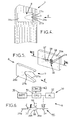
- the figure 1 represents an automatic system for storing cycles 1 such as in particular bicycles, allowing for example to store cycles on the public road so as to make them available to the public.
- This automatic cycle storage system may comprise a plurality of cycle storage stations, one of which is represented on the figure 1 .
- Each cycle storage station comprises a station central station 2, which is here in the form of an interactive terminal equipped with a user interface comprising for example a keyboard 3, a screen 4, an electronic portable card reader 5 , a device 6 for printing tickets, etc.
- the interactive terminal 2 might not include user interface and be a simple communication gateway between the cycle storage station and a central server S.
- the interactive terminal 2 communicates, on the one hand, with the central server S which manages the subscriptions and the rents of cycles, and on the other hand, with a plurality of reception structures 7 which make it possible to lock the cycles during their storage and which can for example be in the form of locking terminals fixed to the ground on the public road.
- Each locking terminal is here adapted to allow the locking of a single cycle 1, and thus constitutes a single cycle locking station.
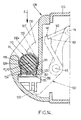
- each reception structure 7 comprises a keeper 8 forming a rigid housing having a notched opening 9 open horizontally and adapted to receive and retain a locking member 10 belonging to a locking device 11 secured for example to the frame 1a d ' one of the cycles 1.
- the locking device 11 may comprise a support 12, which may for example be made in two parts 12a, 12b, secured together by gripping one of the tubes of the frame 1a of the cycle.
- the locking member 10 may optionally be movably mounted on the support 12 so as to allow a certain clearance of the locking member 10 at least vertically with respect to said cycle, as explained in the document EP-A-1,820,721 .
- the locking member 10 may be pivotally mounted relative to the support 12, about a horizontal axis of rotation X1 perpendicular to the mean plane of the locking member 10.
- the locking member 10 comprises a vertical metal plate 10a which is secured to a cylindrical hub 13 of revolution having a central axis X2 parallel to the axis X1 and offset with respect to X1, the hub 13 being itself secured to a lever arm 14 which is pivotally mounted on the support 12 around of the axis of rotation X1.
- the locking member 10 could comprise a number of electrical contacts 19 different from three (for example two contacts).
- the electrical contacts 19 allow, when the cycle 1 is locked on a host structure 7, electrically connect said host structure to an electrical circuit 22 belonging to the cycle 1, shown on the figure 7 .
- the notched opening 9 of the striker 8 advantageously comprises two guides 27a in the form of ramps converging towards one another in the horizontal direction of engagement E of the locking member 10 in the striker 8.
- These guides 27a are adapted to cooperate with the plate 10a of the locking member to move the locking member 10 about the axis of rotation X1 to a nominal locking position relative to the striker 8. It ensures that the locking member 10 and more particularly the recess 15 of this locking member, is at a good height relative to the striker 10 after insertion into said striker, in the engagement direction E.
- the keeper 8 comprises a housing 28a, including for example the notched opening 9 and the guides 27a, and a base 29a.
- the electrical contacts 34 may in particular be in the form of pins protruding from the base 29 and adapted to come into contact respectively with the electrical contacts 19 of the locking member when the cycle is locked on the locking terminal 7.
- the electrical contacts 34 may for example be substantially aligned vertically between them ; they are electrically isolated from each other for example by the housing of the base 29a, which may be made of electrically insulating material.
- the base 29 also comprises a fastening member 37 such as for example a hook pivotally mounted about a vertical axis Z and having a spout 38 projecting from the base 29a.
- the hook 37 is resiliently biased towards a rest position in which the spout 38 protrudes with respect to the base 29, so that when the locking member 10 is engaged in the striker 8 in the engagement direction E, the spout 38 is pushed back into a retracted position by cooperation between an inclined surface 38a of the spout 38 and the front edge of the plate 10a, then said spout 38 engages in the recess 15 of the plate 10a while retaining said plate by cooperation between a stop edge 38b belonging to the spout and the outer edge 17 of the recess 15.
- the hub 13 of the locking member is preferably in contact with the end edge 27b of the notched opening 9 of the cover 28a, so that the cycle 1 is then locked on the locking terminal 7
- the relative positions of the spout 38 and the contacts 34-36 relative to the locking member 10 are shown in phantom on the figure 7 in the cycle 1 lock position on the lock terminal 7.
- the hooking member 37 can also be moved to a position retracted by the electromagnet 33, to allow cycle 1 to be removed from the locking terminal 7.
- the locking member 10 is elastically biased towards a rest position by a spring 39.
- Each locking terminal 7 is autonomous and is therefore not connected externally by any power supply cable and by any low current data transmission cable, which greatly facilitates the installation of the terminals 7.
- a user wants to take a cycle 1 on one of the locking terminals 7, he can for example insert a portable electronic card in the reader 5 of the interactive terminal 2 and enter a secret code using the keyboard 3, so to identify with said interactive terminal.
- the interactive terminal 2 After verifying the rights of the user with the server S, the interactive terminal 2 gives a locking authorization to one of the locking terminals 7, so that a user can unlock the cycle 1 in place on this terminal. pressing the aforementioned button 7c.
- the user can then take cycle 1, and the electronic central unit 31 of the cycle then marks the removal of cycle 1 since it can no longer communicate with the electronic central unit 23 of this cycle.
- the electronic central unit 31 of the locking terminal 7 then informs the interactive terminal 2 of this removal.
- the locking member 10 pivots about the pivot axis X1, being guided by the guides 217a of the striker 8, so that the recess 15 of said locking member is perfectly in correspondence with the spout 38 of the latching member and so that the electrical contacts 19 of the cycle are perfectly in correspondence with the electrical contacts 34 of the striker.
- the electronic central unit 31 of the locking terminal can then communicate with the electronic central unit 23 of the cycle via at least some of the contacts 19 and 34 so as to identify the cycle and to inform the interactive terminal 2 because the cycle has been rendered.
- the power supply circuit 22 of the cycle 1 then feeds the supply circuit 30 to the lock terminal 7 via at least some of the contacts 19, 34, and the two circuits are designed so that the battery 25 of the cycle, previously loaded by the dynamo 26 of the cycle, can thus recharge the battery 36 of the terminal 7.
- the power supply circuits 24, 32 of the cycle and the host structure are adapted to allow reloading of the battery 36 of the host structure by the battery 25 of the cycle as long as the electrical energy storage device of the cycle has a load greater than a minimum non-zero load level, for example at least 10% of its load nominal (in other words, it avoids completely discharging the battery 25 of the cycle by recharging the battery 36).
- the data transmission between the central units 23, 31 could be done by wireless link (for example by a very short-range radio link, in particular an RFID link) in all the embodiments of the invention.
- wireless link for example by a very short-range radio link, in particular an RFID link
- the battery 25 of the cycle and / or the battery 36 of the host structure could be replaced by any other electrical energy storage device, for example supercapacitors or others.
- the battery 36 or other electrical energy storage device of the reception structure could possibly be suppressed, in which case the reception structure 7 would be supplied with electrical energy by the battery or other storage device. Cycle energy, only when the cycle is locked on the host structure 7.
- the automatic system for storing cycles can, as previously, comprise a central server S communicating with central stations 2 of storage station as described above, each communicating by wireless link, in particular by a link short-range radio of the type of those described above, with a plurality of cycle reception structure 107, here constituted by locking terminals.
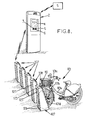
- the cycles 101 of the automatic cycle storage system can be in particular bicycles comprising a frame 101a and a front fork 101b integral with the handlebar 101c and yet the front wheel 101d of the cycle, as can be seen in more detail on the figure 9 .
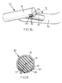
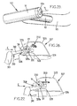
- the front fork 101b of the cycle is integral with a locking member 110, for example a metal member, which may have a general shape of T.
- This locking member 110 may for example comprise a rigid transverse bar 111 which extends longitudinally along an axis Y1 horizontal and perpendicular to the direction of advance of the cycle in the normal position of use of the cycle.
- the crossbar 111 may have a substantially circular section centered on the axis Y1, and it is integral with a rigid connecting member 112, for example a metal rod which extends substantially horizontally forwardly from a rigid support 113 integral with the front fork 101b of the cycle.
- the locking member 110 has electrical contacts 119 made of electrically conductive material. In the example made here, these contacts may in particular be two in number, and they may be formed for example in the vicinity of one end of the crossbar 111.
- the electrical contacts 119 can be made in the lower part of the bar
- This transverse bar 111 may in particular be made in the form of a metal tube having a cutout 121 in the vicinity of one of its axial ends and the electrical contacts 119 may be arranged in this cutout 121.
- the electrical contacts 119 may be carried by an insulating matrix 118 made for example of plastic, which insulating matrix may for example be molded or nested within the tubular transverse bar 111.
- the electrical contacts 119 are connected to the electric circuit 22 of the cycle in the same way as the electrical contacts 19 of the embodiment described above and this electrical circuit is similar to that described above, as shown in FIG. figure 19 .
- each locking terminal 107 has an upwardly open keeper 108 which is adapted to receive the transverse bar 111 of the locking member 110 of a cycle, by engagement in a substantially vertical engagement direction E.
- the striker 108 may for example be in the form of a rigid metal housing 122 which forms the front face of a transverse upper portion 123 of the terminal 107, which upper transverse portion extends horizontally between two vertical lateral uprights 124 fixed on the ground. These uprights 124 define between them a vertical slot 125 extending down to the ground level and adapted to receive the front wheel 101d of a cycle 101 locked on the locking terminal 107, as can be seen on the figures 8 and 12 .
- the slot 125 may for example have a width of between 7 and 12 cm.
- the terminal 107 may optionally comprise, as the terminal 7, various accessories provided for example on its upper face, for example a contactless card reader 107a, a light 107b and a control button 107c which can for example, to trigger the unlocking of a cycle 101 locked on the terminal 107 once acquired unlocking authorization.
- various accessories provided for example on its upper face, for example a contactless card reader 107a, a light 107b and a control button 107c which can for example, to trigger the unlocking of a cycle 101 locked on the terminal 107 once acquired unlocking authorization.
- the housing 122 of the striker 108 may for example have a substantially vertical front wall 126 which, when the locking member 110 of the cycle is engaged in the striker 108, is parallel to the axis Y1 of the transverse bar 111.
- This front wall 126 is flanked by two side walls 127 projecting towards the front of the locking terminal 107, that is to say towards the cycle 101 when it is locked on said locking terminal.
- These two side walls 127 extend substantially vertically and substantially perpendicularly to the front wall 126, and they are spaced from each other by a distance substantially corresponding to the horizontal length of the transverse bar 111, so that that the keeper 108 can receive said crossbar 111 between the two side walls 127, substantially without play or with a small clearance.
- Each side wall 127 further comprises, in its lower part, an upwardly open receiving trough 128, which forms, with the front wall 126, a substantially J-shaped section.
- the two receiving troughs 128 are adapted to receiving both axial ends of the transverse bar 111 of the cycle locking member by vertical downward engagement in the direction E.
- the striker 108 comprises electrical contacts 134 of electrically conductive material, which are for example two in number and which together form an electrical interface 135.
- These electrical contacts 134 may for example be embedded in a matrix of insulating materials 136, for example plastic material, and are connected to the electrical circuit 30 of the lock terminal 107, shown on the figure 19 , who is identical or similar to the electrical circuit previously described with regard to Figures 1 to 7 .
- the electrical interface 135 is disposed in an upwardly open cutout 137 formed in the bottom of one of the receiving troughs 128, and the electrical contacts 134 are arranged so that the electrical contacts 119 of the the locking member of the cycle bear respectively against the different electrical contacts 134 of the locking terminal 107.
- the bottom of the receiving troughs 128 has a circular shape centered on a horizontal axis Y2 which, when the cycle is locked on the locking terminal 107 coincides with the axis Y1 of the crossbar 111.
- the contacts 134 are also arranged in a circular contour centered on the axis Y2, so that the electrical contacts 119, 134 do not interfere with any rotational movement of the crossbar 111 about the axis Y1, Y2 when the cycle is locked on the lock terminal 107.
- the electrical contacts 119, 134 are shaped so as to be in mutual contact over a certain angular range of relative positions between the transverse bar 111 and the striker 108 (for example a range of 10 to 20 degrees), thus making it possible to preserve the electrical connection between the cycle 101 and the lock terminal 107 even if the transverse bar 111 of the cycle lock member is not in a nominal angular position with respect to the terminal 107.
- the front wall 126 of the keeper casing 108 may for example have two vertical slots 129 through which two latch plates 130 protrude which project towards the front of the locking terminal 107, i.e. to the cycle 101, parallel to the two side walls 127.
- both Lock plates 130 may be metal parts which are connected to one another at the rear of the front wall 126 by a transverse rear wall 131, so as to form together with this rear wall, a piece of rigid one-piece lock 132.
- Each latch plates 130 furthermore has, in its front part protruding out of slots 129 of the front wall 126, notches 133 in the shape of an arc of a circle which may each extend over approximately 180 degrees and which have a diameter corresponding substantially to outer diameter of the crossbar 111 of the cycle, so as to receive the crossbar as will be explained below.
- Each of the latches 130 forms, on either side of the notch 133 corresponding, an upper spout and a lower spout respectively constituting a locking member 130a and an actuating member 130b.
- the notches 133 are oriented substantially horizontally forward so that the transverse bar 111 engaged in these notches 133 is blocked in the receiving troughs 128 and prevented from exiting these troughs receiving by the locking members 130a of the two lock plates (see figure 14 ).
- the notches 133 form with the receiving trough 128 an inner arcuate contour centered on the axis Y2, which allows the crossbar 111 to rotate freely about its axis Y1, as mentioned above.
- the frame 101a of the cycle 101 can freely rotate about the vertical axis of the handlebar 101c, so that the cycle can not easily be broken or disassociated from the terminal 107 by vandalism: the frame 101a of the cycle can not be used by vandals as a lever arm to exert a significant force on the locking cycle 101 at terminal 107.
- the protection of the cycle 101 during storage is further enhanced by the fact that the terminal 107 at least partially protects the front wheel 101d of the cycle.
- the latch piece 132 is pivotally mounted about an axis of rotation Y3 parallel to the aforementioned axis Y2, for example by means of a swivel rod 136 mounted swirling on two parallel vertical flanges 137 (see FIG. figure 15 ) extending perpendicularly rearwardly from the front wall 126 of the housing 122.
- the latch piece 132 is further biased upwards, towards an unlocking position which will be described below, by means of a spring 138.
- the spring 138 may for example be a wire spring comprising two windings 139 wound around the axis Y3 on either side of the rear wall of the wall 131 of the latch piece, each of these windings being extended on the one hand by an end branch 139a ( figures 15 and 16 ) which bears on the corresponding flange 137 and on the other hand, by a central portion 140 of the stirrup-shaped elastic wire, bearing in the lower part of the rear wall 131.
- the rear wall 131 of the lock piece further comprises, in its upper part, a stop zone 141, which is oriented towards the rear and which is delimited downwards by an upwardly directed shoulder 142 also belonging to said rear wall 131 (see figures 17 and 18 ).
- the actuating rod 148 is normally resiliently biased backwards, that is to say in the extended position of the rod 148, by means of an internal spring (not shown) housed in the body 146, so as to bias the trigger 143 to its stop position where the front end 145 of the trigger 143 abuts against the stop 141 of the lock piece.
- the body 147 of the actuator 146 includes a solenoid which, when traversed by an electric current, pulls the actuating rod 148 into a retracted position which causes the trigger 143 to pivot into a retracted position where said trigger 143 is above the abutment 141 of the latch piece, allowing said latch piece 132 to pivot rearwardly about the axis of rotation Y3 so that the notches 133 of the latch plates 130 is oriented substantially upwards, in the unlocking position.
- the electrical power supply of the electric actuator 146 is brief, for example less than ten seconds and advantageously less than five seconds, since it is simply intended that the trigger 143 does not interfere any more with the stop 141 of the latch piece at the beginning of the pivoting movement towards the rear of said latch piece: once this pivoting has been initiated, the power supply of the actuator 146 can be stopped, after which the trigger 143 is again urged downward, and said trigger then simply bears against the circular upper surface 130a of the latch plates 130 without interfering with the pivoting of the latch piece 132.
- the power consumption of the actuator 146 is therefore very low.
- the transverse bar 111 of the cycle when locked to the lock terminal 107 is pressed vertically downwardly on the actuating members 130b of the lock plates, thereby pivoting the lock member 132 down against the elastic biasing of the spring 138 until that the trigger 143 can engage behind the abutment 141 of the latch piece resting on the shoulder 142 of said latch piece, after which the latch piece is again in the locking position even represented on the Figures 13 to 18 .
- the second embodiment of the invention differs from the first embodiment only in that the host structure 207 is here a horizontal metal beam which is fixed to the ground by lateral uprights 207a, this beam including several locking stations cycles corresponding to several strikes 108 identical or similar to those already described above, fixed on one of the vertical faces or on both vertical faces of the beam 207.
- the host structure 207 is here a horizontal metal beam which is fixed to the ground by lateral uprights 207a, this beam including several locking stations cycles corresponding to several strikes 108 identical or similar to those already described above, fixed on one of the vertical faces or on both vertical faces of the beam 207.
- each cycle storage station may comprise one or more reception structures 207.
- the electrical circuit 30 may be reproduced for each striker 108, or some elements of the electrical circuit 30 may be common to all strikes 108, including the electronic central unit 31, at least one part of the power supply circuit 32, the battery 36 and the communication interface 40.
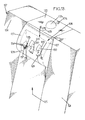
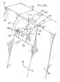
- the cycles 301 are similar to the cycles 101 described above, with a frame 301a which carries a front fork 301b integral with the handlebar 301c and carrying the front wheel 301d, the front fork 301b being integral with rigid supports 313, for example in the form of two lateral flanges which extend parallel to each other forwards and upwards from the two branches of the fork 301b.
- these lateral flanges 313 carry a locking member 310 in the general shape of T, comprising a rigid transverse bar 311, similar to the rigid transverse bar 111, previously described, and a rigid connecting member 312 which extends forwardly. from the flanges 313.
- the cycles 301 can be locked on cycle home structures 307, here constituted by locking terminals, one of which is represented on the figure 25 .
- This locking terminal 307 has a general structure similar to the locking terminal 107 previously described in the first embodiment, with a transverse upper portion 123 which carries a keeper 308 adapted to receive and lock the locking member.
- locking cycle 310 this upper transverse portion 323 extending horizontally between two vertical lateral uprights 124 integral with a base 324a itself attached to the ground.
- the base 324a may be provided so that the front wheel 301d of the cycle rests on said base when the cycle is locked on the locking terminal 307, which makes it possible to control the height of the locking member 310 of the cycle relative to at the waste 308.
- the striker 308 may optionally be open horizontally in a direction of engagement E, and said striker 308 may comprise, at each of the axial ends of the transverse bar 311 a trough 328 open horizontally and whose bottom wall 328a serves for the crossbar 311, when said crossbar 311 is engaged horizontally in the trough 308, as shown in FIGS. Figures 26 and 27 .
- the keeper 308 further comprises an electric lock which may for example comprise two lock plates 330 similar to the lock plates 130 previously described, each having a notch 333 adapted to receive the crossbar 311. As shown in FIG. figure 27 each latch plate 330 is adapted to pivot about an axis of rotation Y3 between an unlocked position where the notch 333 is open horizontally towards the mouth of the striker 308 to receive the transverse bar 311 ( figure 26 ) and a locked position where the notch 333 is oriented downwards, substantially 90 ° from the unlocked position, thereby blocking the transverse bar 333 against the bottom wall 328a of the trough 328.
- the operation of the electric lock and in particular lock plates 330 is therefore identical to that of the first embodiment described above.
- the frame of the cycle 301 may possibly be raised during an attempt at vandalism, without this attempt giving rise to a deterioration of the cycle 301 or the locking terminal 307, since the crossbar 311 can then rotate on itself about the axes Y1, Y2.
- the aforementioned lock plates 330 are controlled by a control mechanism 350 which may be similar to that described in the first embodiment of the invention, or preferably similar to that described in the document FR-A-2 905 927 .
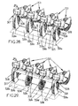
- the host structure of cycles could comprise two locking terminals 307 interconnected by a transverse beam 307a having on one or two of its vertical faces, strikes 308 as previously described.
- the receiving structure further comprises additional bases 324a, each provided for example with a guide 324d for the front wheels of the cycles, in correspondence with the latches 308 of the horizontal beam 307a.
- the various bases 324a, 324c are interconnected, as in the example of FIG. figure 28 , by connecting plates 324b themselves fixed to the ground.
- the locking member 310 of the cycle may optionally be elastically connected to the lateral flanges 313, so as to be able to rotate about a horizontal axis Y5 parallel to the axis Y1, in the direction of the double arrow 311a.
- the respective electrical circuits of the cycle and of the host structure operate under the same voltage and preferably at low voltage (for example 3V or 6V) so as to be insensitive to the presence of water at the electrical contacts 19, 119, 119a, 34, 134, 134a.
Landscapes
- Engineering & Computer Science (AREA)
- Mechanical Engineering (AREA)
- Transportation (AREA)
- Power Engineering (AREA)
- Chemical & Material Sciences (AREA)
- Combustion & Propulsion (AREA)
- Lock And Its Accessories (AREA)
- Charge And Discharge Circuits For Batteries Or The Like (AREA)
- Secondary Cells (AREA)
- Automatic Disk Changers (AREA)
Applications Claiming Priority (2)
| Application Number | Priority Date | Filing Date | Title |
|---|---|---|---|
| FR0959442A FR2954265B1 (fr) | 2009-12-22 | 2009-12-22 | Systeme automatique de stockage de cycles, cycle pour un tel systeme et structure d'accueil pour un tel cycle. |
| EP10163037.4A EP2338779B1 (de) | 2009-12-22 | 2010-05-17 | Automatisches System zur Lagerung von Fahrrädern, Fahrrad für ein solches System und Aufnahmestruktur für ein solches Fahrrad |
Related Parent Applications (2)
| Application Number | Title | Priority Date | Filing Date |
|---|---|---|---|
| EP10163037.4A Division-Into EP2338779B1 (de) | 2009-12-22 | 2010-05-17 | Automatisches System zur Lagerung von Fahrrädern, Fahrrad für ein solches System und Aufnahmestruktur für ein solches Fahrrad |
| EP10163037.4A Division EP2338779B1 (de) | 2009-12-22 | 2010-05-17 | Automatisches System zur Lagerung von Fahrrädern, Fahrrad für ein solches System und Aufnahmestruktur für ein solches Fahrrad |
Publications (2)
| Publication Number | Publication Date |
|---|---|
| EP2778034A2 true EP2778034A2 (de) | 2014-09-17 |
| EP2778034A3 EP2778034A3 (de) | 2016-06-22 |
Family
ID=42356881
Family Applications (2)
| Application Number | Title | Priority Date | Filing Date |
|---|---|---|---|
| EP14166519.0A Withdrawn EP2778034A3 (de) | 2009-12-22 | 2010-05-17 | Automatisches System zur Speicherung von Zyklen, Zyklus für ein solches System und Aufnahmestruktur für einen solchen Zyklus |
| EP10163037.4A Not-in-force EP2338779B1 (de) | 2009-12-22 | 2010-05-17 | Automatisches System zur Lagerung von Fahrrädern, Fahrrad für ein solches System und Aufnahmestruktur für ein solches Fahrrad |
Family Applications After (1)
| Application Number | Title | Priority Date | Filing Date |
|---|---|---|---|
| EP10163037.4A Not-in-force EP2338779B1 (de) | 2009-12-22 | 2010-05-17 | Automatisches System zur Lagerung von Fahrrädern, Fahrrad für ein solches System und Aufnahmestruktur für ein solches Fahrrad |
Country Status (11)
| Country | Link |
|---|---|
| US (1) | US20110148346A1 (de) |
| EP (2) | EP2778034A3 (de) |
| JP (1) | JP5638931B2 (de) |
| CN (1) | CN102101503A (de) |
| AU (1) | AU2010257218A1 (de) |
| CA (1) | CA2725081A1 (de) |
| ES (1) | ES2628110T3 (de) |
| FR (1) | FR2954265B1 (de) |
| PT (1) | PT2338779T (de) |
| SG (1) | SG172572A1 (de) |
| SI (1) | SI2338779T1 (de) |
Cited By (1)
| Publication number | Priority date | Publication date | Assignee | Title |
|---|---|---|---|---|
| WO2026055755A1 (pt) * | 2024-09-13 | 2026-03-19 | M2 Soluções Em Engenharia Ltda. | Dispositivo de acoplamento, estação de acoplamento e sistema de acoplamento |
Families Citing this family (107)
| Publication number | Priority date | Publication date | Assignee | Title |
|---|---|---|---|---|
| EP3333280B1 (de) | 2007-09-12 | 2026-04-01 | Flisom AG | Verfahren zur herstellung einer verbindungsschicht mit zusammensetzungsgradierung |
| USD674334S1 (en) * | 2010-10-07 | 2013-01-15 | Ecotality, Inc. | Electric vehicle charging station |
| US9123035B2 (en) | 2011-04-22 | 2015-09-01 | Angel A. Penilla | Electric vehicle (EV) range extending charge systems, distributed networks of charge kiosks, and charge locating mobile apps |
| US10217160B2 (en) | 2012-04-22 | 2019-02-26 | Emerging Automotive, Llc | Methods and systems for processing charge availability and route paths for obtaining charge for electric vehicles |
| US9285944B1 (en) | 2011-04-22 | 2016-03-15 | Angel A. Penilla | Methods and systems for defining custom vehicle user interface configurations and cloud services for managing applications for the user interface and learned setting functions |
| CN102268939A (zh) * | 2011-06-23 | 2011-12-07 | 湖北盛佳电器设备有限公司 | 电子群锁系统 |
| EP2737594B1 (de) | 2011-07-26 | 2019-02-13 | Gogoro Inc. | Vorrichtung, verfahren und artikel für einen raum für eine energiespeichervorrichtung |
| US9437058B2 (en) | 2011-07-26 | 2016-09-06 | Gogoro Inc. | Dynamically limiting vehicle operation for best effort economy |
| JP5960260B2 (ja) | 2011-07-26 | 2016-08-02 | ゴゴロ インク | 電力蓄積デバイスの収集、充電、および分配マシンの場所を提供するための装置、方法、および物品 |
| US9129461B2 (en) | 2011-07-26 | 2015-09-08 | Gogoro Inc. | Apparatus, method and article for collection, charging and distributing power storage devices, such as batteries |
| CN103858272B (zh) | 2011-07-26 | 2017-07-07 | 睿能创意公司 | 用于电动马达驱动车辆的组件的热管理 |
| JP6026535B2 (ja) | 2011-07-26 | 2016-11-16 | ゴゴロ インク | 予約電力蓄積デバイス収集、充電、および分配マシンにおける電力蓄積デバイスの予約を行なうための装置、方法、および物品 |
| TWI560637B (en) | 2011-07-26 | 2016-12-01 | Gogoro Inc | Apparatus, method and article for providing information regarding availability of power storage devices at a power storage device collection, charging and distribution machine |
| JP6422119B2 (ja) | 2011-07-26 | 2018-11-14 | ゴゴロ インク | 収集充電分配装置間でバッテリなどの電力貯蔵装置を再分配するための装置、方法及び物品 |
| EP2737597B1 (de) | 2011-07-26 | 2019-10-16 | Gogoro Inc. | Vorrichtung, verfahren und artikel zur physischen sicherheit von energiespeichereinrichtungen bei fahrzeugen |
| JP5793245B2 (ja) * | 2011-07-26 | 2015-10-14 | ゴゴロ インク | 乗り物診断データを提供するための装置、方法、および物品 |
| TWI581541B (zh) | 2011-07-26 | 2017-05-01 | 睿能創意公司 | 用於認證、保全及控制如電池組之電力儲存器件之裝置、方法及物品 |
| US10186094B2 (en) | 2011-07-26 | 2019-01-22 | Gogoro Inc. | Apparatus, method and article for providing locations of power storage device collection, charging and distribution machines |
| EP2737599B1 (de) | 2011-07-26 | 2018-10-10 | Gogoro Inc. | Vorrichtung, verfahren und artikel zur authentifizierung, sicherheit und steuerung von energiespeichereinrichtungen, wie etwa batterien, auf der basis von benutzerprofilen |
| CN102561810B (zh) * | 2012-01-16 | 2014-04-30 | 谢瑞初 | 方便收发车锁钥匙的锁车车位系统及其存车方法 |
| FR2987811B1 (fr) | 2012-03-12 | 2014-04-18 | Jcdecaux Sa | Systeme automatique de stockage de cycles et poste de verrouillage de cycle pour un tel systeme |
| US9041344B2 (en) * | 2012-05-25 | 2015-05-26 | Timotion Technology Co., Ltd. | Standby battery box for electric cylinder |
| FR2991658B1 (fr) * | 2012-06-11 | 2016-04-01 | Jcdecaux Sa | Systeme automatique de stockage de cycles et cycle pour un tel systeme. |
| WO2014052329A1 (en) | 2012-09-25 | 2014-04-03 | Scoot Networks, Inc. | Systems and methods for regulating vehicle access |
| BR112015011290A2 (pt) | 2012-11-16 | 2017-07-11 | Gogoro Inc | aparelho, método e artigo para sinais de realização de curva de veículo |
| US9854438B2 (en) | 2013-03-06 | 2017-12-26 | Gogoro Inc. | Apparatus, method and article for authentication, security and control of portable charging devices and power storage devices, such as batteries |
| BR112015023244A2 (pt) | 2013-03-12 | 2017-07-18 | Gogoro Inc | aparelho, processo e artigo para alterar planos de troca de dispositivos de armazenamento de energia elétrica portáteis |
| US11222485B2 (en) | 2013-03-12 | 2022-01-11 | Gogoro Inc. | Apparatus, method and article for providing information regarding a vehicle via a mobile device |
| US8798852B1 (en) | 2013-03-14 | 2014-08-05 | Gogoro, Inc. | Apparatus, system, and method for authentication of vehicular components |
| JP6462655B2 (ja) | 2013-03-15 | 2019-01-30 | ゴゴロ インク | 蓄電デバイスの収集および分配のためのモジュラーシステム |
| FR3003535B1 (fr) * | 2013-03-21 | 2016-03-25 | Jcdecaux Sa | Systeme automatique de stockage de cycles et batterie pour un tel systeme. |
| FR3003536B1 (fr) * | 2013-03-21 | 2016-04-15 | Jcdecaux Sa | Systeme automatique de stockage de cycles et batterie pour un tel systeme. |
| CN103359201B (zh) * | 2013-07-16 | 2015-10-21 | 上海理工大学 | 自行车停车系统 |
| US9770996B2 (en) | 2013-08-06 | 2017-09-26 | Gogoro Inc. | Systems and methods for powering electric vehicles using a single or multiple power cells |
| TWI644194B (zh) | 2013-08-06 | 2018-12-11 | 睿能創意公司 | 電能儲存裝置熱分布調節控制器、方法及其電動車系統 |
| CN103473859A (zh) * | 2013-09-04 | 2013-12-25 | 武汉绿时代共享交通科技有限公司 | 一种公共自行车租赁站集成管理柜 |
| TWM477980U (zh) * | 2013-10-24 | 2014-05-11 | Giant Mfg Co Ltd | 自行車駐車鎖 |
| US9124085B2 (en) | 2013-11-04 | 2015-09-01 | Gogoro Inc. | Apparatus, method and article for power storage device failure safety |
| TWI626183B (zh) | 2013-11-08 | 2018-06-11 | 睿能創意公司 | 用於提供車輛事件資料的裝置、方法與物品 |
| TWI645646B (zh) | 2014-01-23 | 2018-12-21 | Gogoro Inc. | 使用以矩陣佈置的電能儲存器之系統和方法 |
| WO2016025392A1 (en) | 2014-08-11 | 2016-02-18 | Gogoro Inc. | Multidirectional electrical connector, plug and system |
| USD730780S1 (en) | 2014-08-15 | 2015-06-02 | Technologies Bewegen Inc. | Bicycle |
| USD746760S1 (en) | 2014-08-15 | 2016-01-05 | Technologies Bewegen Inc. | Bicycle basket |
| USD730779S1 (en) | 2014-08-15 | 2015-06-02 | Technologies Bewegen Inc. | Electric bicycle |
| USD766138S1 (en) | 2014-08-15 | 2016-09-13 | Technologies Bewegen Inc. | Base station for a bicycle sharing system |
| USD776576S1 (en) | 2014-08-18 | 2017-01-17 | Technologies Bewegen Inc. | Electric bicycle |
| USD730781S1 (en) | 2014-08-18 | 2015-06-02 | Technologies Bewegen Inc. | Electric bicycle |
| USD738276S1 (en) | 2014-08-18 | 2015-09-08 | Technologies Bewegen Inc. | Bicycle handlebar |
| CN110481360B (zh) | 2014-09-04 | 2023-06-16 | 睿能创意公司 | 可携式电能储存器的充电模块 |
| USD789883S1 (en) | 2014-09-04 | 2017-06-20 | Gogoro Inc. | Collection, charging and distribution device for portable electrical energy storage devices |
| JP6435084B2 (ja) * | 2014-09-24 | 2018-12-05 | 株式会社ベルニクス | 電動二輪・三輪車用非接触給電装置 |
| WO2016091319A1 (de) * | 2014-12-12 | 2016-06-16 | Energytube Holding Gmbh | Sicherungsvorrichtung und befestigungsvorrichtung zum sichern von fahrzeugen |
| CN106143758A (zh) * | 2015-04-21 | 2016-11-23 | 重庆通盛建设工业有限公司 | 一种带充电结构的自行车前叉总成 |
| CN104882927A (zh) * | 2015-05-14 | 2015-09-02 | 珠海鼎蓝科技有限公司 | 一种多功能公共自行车站台系统 |
| KR101720949B1 (ko) * | 2015-05-22 | 2017-03-29 | 변종섭 | 이동수단의 주차시스템 |
| EP3303048B1 (de) | 2015-06-05 | 2022-11-16 | Gogoro Inc. | Systeme und verfahren zur fahrzeugladungserkennung und reaktion |
| ES2550688B1 (es) * | 2015-07-08 | 2016-09-19 | Clear Channel España S.L.U. | Sistema de anclaje de bicicleta eléctrica, puerto para depositar bicicletas, bicicleta eléctrica y estación para depositar bicicletas |
| CN104967183B (zh) * | 2015-07-22 | 2017-12-22 | 董国军 | 充电方舱用手机充电装置 |
| US10723399B2 (en) * | 2015-08-05 | 2020-07-28 | Lyft, Inc. | Cycle management system with locking mechanism |
| CN105553039B (zh) * | 2016-02-05 | 2022-03-08 | 永安行科技股份有限公司 | 电动助力自行车系统及其充电方法 |
| CN105835998B (zh) * | 2016-04-27 | 2018-06-15 | 永安行科技股份有限公司 | 助力自行车及其联接器 |
| WO2017217929A1 (en) * | 2016-06-16 | 2017-12-21 | Neuron Mobility Pte Ltd. | Docking station for motorised vehicles |
| SG10201604920YA (en) * | 2016-06-16 | 2018-01-30 | Neuron Mobility Pte Ltd | Short Distance Mobility Sharing System |
| FR3053953B1 (fr) | 2016-07-18 | 2019-09-13 | Jcdecaux Sa | Systeme automatique de stockage de cycles, cycle et poste de verrouillage pour un tel systeme |
| FR3054352A1 (fr) * | 2016-07-22 | 2018-01-26 | Metrolab | Dispositif de stockage de vehicules electriques legers partages |
| CN108001568A (zh) * | 2016-11-23 | 2018-05-08 | 深圳乐行天下科技有限公司 | 电动代步车 |
| WO2018107978A1 (en) * | 2016-12-12 | 2018-06-21 | Dongxia Datong (Beijing) Management And Consulting Co., Ltd. | Systems and methods for determining abnormal information associated with a vehicle |
| US11072295B2 (en) * | 2017-02-22 | 2021-07-27 | Ford Global Technologies, Llc | Autonomous bus bicycle rack |
| FR3063970B1 (fr) | 2017-03-20 | 2023-03-24 | Jcdecaux Sa | Systeme automatique de mise a disposition de cycles |
| DE102017218226A1 (de) * | 2017-03-20 | 2018-09-20 | Fraunhofer-Gesellschaft zur Förderung der angewandten Forschung e.V. | Unterflur-Kontaktsystem |
| US10858015B2 (en) * | 2017-06-23 | 2020-12-08 | Bombardier Transportation Gmbh | Rail vehicle having a dedicated area for recharging light electric vehicles |
| TW201908164A (zh) * | 2017-07-14 | 2019-03-01 | 見發先進科技股份有限公司 | 電動車的充電結構 |
| EP3653028B1 (de) * | 2017-07-14 | 2024-09-18 | Pbsc Urban Solutions Inc. | System und verfahren zum sichern, wiederaufladen und betrieb eines elektrischen fahrrades |
| US10377444B2 (en) * | 2017-07-31 | 2019-08-13 | Shimano Inc. | Bicycle electric component |
| US10407116B2 (en) | 2017-08-14 | 2019-09-10 | LINKA Group Ltd. | Electronic security system for bicycle |
| CN107415763B (zh) * | 2017-09-07 | 2023-12-19 | 青岛特来电新能源科技有限公司 | 充电设备和充电系统 |
| WO2019063948A2 (fr) * | 2017-09-29 | 2019-04-04 | Birota | Véhicule à propulsion humaine apte à un stockage compact |
| TWI678307B (zh) * | 2017-11-21 | 2019-12-01 | 微程式資訊股份有限公司 | 用於自行車的智能鎖控結構 |
| US11697392B2 (en) * | 2017-12-01 | 2023-07-11 | Gogoro Inc. | Security mechanisms for electric motors and associated systems |
| CN107767662A (zh) * | 2017-12-05 | 2018-03-06 | 左勤 | 一种为多种共享单车提供共享停车位的方法和系统 |
| EP3503313B1 (de) * | 2017-12-20 | 2022-02-09 | Amprio GmbH | Mehrbatterie-adapter zur herstellung einer elektrischen verbindung zwischen mindestens zwei traktionsbatterien einerseits und einer antriebseinheit eines elektrofahrrades andererseits |
| CN108248723B (zh) * | 2018-02-12 | 2024-01-12 | 辽宁工业大学 | 一种滑动式自行车停车架及其模糊匹配停车方法 |
| WO2019204144A1 (en) * | 2018-04-16 | 2019-10-24 | Bird Rides, Inc. | On-demand rental of electric vehicles |
| US11215981B2 (en) | 2018-04-20 | 2022-01-04 | Bird Rides, Inc. | Remotely controlling use of an on-demand electric vehicle |
| CN108482531B (zh) * | 2018-04-20 | 2023-06-02 | 汕头大学 | 一种模块式的自动存取立式自行车架 |
| FR3082822B1 (fr) * | 2018-06-22 | 2022-07-01 | Noval | Dispositif de verrouillage d’un cycle sur une borne réceptrice, et système automatique de stockage de cycles |
| WO2020023933A2 (en) * | 2018-07-26 | 2020-01-30 | Swiftmile, Inc. | Light electric vehicle parking and charging stations and smart charging systems for the vehicle batteries |
| US11263690B2 (en) | 2018-08-20 | 2022-03-01 | Bird Rides, Inc. | On-demand rental of electric vehicles |
| JP7214524B2 (ja) * | 2019-03-22 | 2023-01-30 | 東芝テック株式会社 | カート収納システム、および、給電システム |
| JP7071943B2 (ja) * | 2019-04-12 | 2022-05-19 | 京セラ株式会社 | 電力管理装置、電力管理システム及び電力管理方法 |
| US20220379983A1 (en) * | 2019-10-13 | 2022-12-01 | WATERMAN Charging System GmbH | Connection System for Connecting a Small Vehicle to a Base Station |
| US12508926B2 (en) * | 2019-10-23 | 2025-12-30 | Acton, Inc. | Docking and recharging system for battery powered personal mobility vehicles |
| US12083915B2 (en) * | 2019-12-16 | 2024-09-10 | Lyft, Inc. | Vehicle docking stations systems and methods |
| US11597285B2 (en) * | 2020-03-06 | 2023-03-07 | Toyota Jidosha Kabushiki Kaisha | Systems, devices, and methods for sharing personal mobility devices |
| CN111622621A (zh) * | 2020-04-20 | 2020-09-04 | 北京骑胜科技有限公司 | 锁具、用于操作锁具的方法和车辆 |
| US10991250B1 (en) * | 2020-05-01 | 2021-04-27 | Lyft, Inc. | Lightweight docking station for micromobility transit vehicles systems and methods |
| US11214322B2 (en) * | 2020-05-12 | 2022-01-04 | Lyft, Inc. | Micromobility transit vehicle lock-to mechanism systems and methods |
| US20210394848A1 (en) * | 2020-06-19 | 2021-12-23 | TWIG Power, LLC | Charging stand for electric motorcycles |
| IT202000017233A1 (it) * | 2020-07-15 | 2022-01-15 | 3M Smart Mobility S R L | Stazione di ricarica per veicoli elettrici, particolarmente veicoli elettrici per mobilita' individuale |
| KR102256807B1 (ko) * | 2020-08-18 | 2021-05-28 | (주)그린파워 | 무선충전 시스템 |
| KR102917183B1 (ko) * | 2020-09-14 | 2026-01-23 | 엘지전자 주식회사 | 개인용 이동장치를 위한 충전 시스템 |
| WO2022063383A1 (en) * | 2020-09-25 | 2022-03-31 | Strim Mobility Sas | Stationary locking module for electrical vehicles of individual mobility |
| JP6880303B1 (ja) * | 2020-11-24 | 2021-06-02 | 本田技研工業株式会社 | シェアリングシステム |
| CN112647772B (zh) * | 2020-12-31 | 2024-04-26 | 金茂智慧科技(广州)有限公司 | 一种智能充电门锁、充电提示方法及装置 |
| CN113428267B (zh) * | 2021-08-02 | 2022-06-14 | 湖南喜宝达信息科技有限公司 | 一种电单车停车桩及其停车锁结构 |
| EP4570569A1 (de) * | 2023-11-30 | 2025-06-18 | Seedia Sp. z o.o. | Netzunabhängiges ladevorrichtungssystem für mobile vorrichtungen und verfahren zur verwaltung der ladung mobiler vorrichtungen |
| FR3167126A1 (fr) | 2024-10-09 | 2026-04-10 | Jcdecaux Se | Système automatique de stockage de cycles, cycle et poste de verrouillage pour un tel système. |
Citations (5)
| Publication number | Priority date | Publication date | Assignee | Title |
|---|---|---|---|---|
| AT4447U1 (de) * | 2000-08-25 | 2001-07-25 | Kurt Haselsteiner | Sperrvorrichtung für fahrräder |
| EP1820721A1 (de) | 2006-02-21 | 2007-08-22 | Jcdecaux SA | Automatisches System zur Speicherung von Zyklen, Zyklus für ein solches System und Sperrvorrichtung für einen solchen Zyklus |
| EP1820722A1 (de) | 2006-02-21 | 2007-08-22 | Jcdecaux SA | Automatische System zur Speicherung von Zyklen |
| FR2905927A1 (fr) | 2006-09-19 | 2008-03-21 | Jcdecaux Sa | Systeme de stockage automatique de cycles,cycle pour un tel systeme et poste de verrouillage pour un tel systeme |
| EP2168848A1 (de) * | 2008-09-24 | 2010-03-31 | Geofoton Soluciones Sostenibles, S.L. | Automatisches Parksystem für elektrische und normale Fahrräder mit Batterieaufladung, Antidiebstahlsperre und Überwachung der Fahrradverwendung |
Family Cites Families (7)
| Publication number | Priority date | Publication date | Assignee | Title |
|---|---|---|---|---|
| JP2004221521A (ja) * | 2002-11-22 | 2004-08-05 | Shin Kobe Electric Mach Co Ltd | 電動車両の充電システム |
| JP2006158087A (ja) * | 2004-11-29 | 2006-06-15 | Yamaha Motor Co Ltd | 電動車両用充電システム |
| JP2006254646A (ja) * | 2005-03-14 | 2006-09-21 | Matsushita Electric Ind Co Ltd | 携帯電子機器用充電器 |
| JP4862153B2 (ja) * | 2006-04-07 | 2012-01-25 | 国立大学法人九州工業大学 | 電力負荷平準化方法及びシステム |
| CN201143962Y (zh) * | 2007-06-28 | 2008-11-05 | 北京软媒视频技术研究院 | 智能立体自行车存放装置 |
| DE102008009012B3 (de) * | 2008-02-13 | 2009-02-26 | ASTRA Gesellschaft für Asset Management mbH & Co. KG | Fahrradsicherungssystem |
| KR20100001311U (ko) * | 2008-07-28 | 2010-02-08 | 김한용 | 자전거를 대여, 회수하는 스테이션 |
-
2009
- 2009-12-22 FR FR0959442A patent/FR2954265B1/fr not_active Expired - Fee Related
-
2010
- 2010-05-17 EP EP14166519.0A patent/EP2778034A3/de not_active Withdrawn
- 2010-05-17 PT PT101630374T patent/PT2338779T/pt unknown
- 2010-05-17 SI SI201031478T patent/SI2338779T1/sl unknown
- 2010-05-17 EP EP10163037.4A patent/EP2338779B1/de not_active Not-in-force
- 2010-05-17 ES ES10163037.4T patent/ES2628110T3/es active Active
- 2010-12-14 US US12/967,736 patent/US20110148346A1/en not_active Abandoned
- 2010-12-14 CA CA 2725081 patent/CA2725081A1/fr not_active Abandoned
- 2010-12-15 SG SG2010093102A patent/SG172572A1/en unknown
- 2010-12-15 AU AU2010257218A patent/AU2010257218A1/en not_active Abandoned
- 2010-12-17 JP JP2010281657A patent/JP5638931B2/ja not_active Expired - Fee Related
- 2010-12-22 CN CN2010106206048A patent/CN102101503A/zh active Pending
Patent Citations (5)
| Publication number | Priority date | Publication date | Assignee | Title |
|---|---|---|---|---|
| AT4447U1 (de) * | 2000-08-25 | 2001-07-25 | Kurt Haselsteiner | Sperrvorrichtung für fahrräder |
| EP1820721A1 (de) | 2006-02-21 | 2007-08-22 | Jcdecaux SA | Automatisches System zur Speicherung von Zyklen, Zyklus für ein solches System und Sperrvorrichtung für einen solchen Zyklus |
| EP1820722A1 (de) | 2006-02-21 | 2007-08-22 | Jcdecaux SA | Automatische System zur Speicherung von Zyklen |
| FR2905927A1 (fr) | 2006-09-19 | 2008-03-21 | Jcdecaux Sa | Systeme de stockage automatique de cycles,cycle pour un tel systeme et poste de verrouillage pour un tel systeme |
| EP2168848A1 (de) * | 2008-09-24 | 2010-03-31 | Geofoton Soluciones Sostenibles, S.L. | Automatisches Parksystem für elektrische und normale Fahrräder mit Batterieaufladung, Antidiebstahlsperre und Überwachung der Fahrradverwendung |
Cited By (1)
| Publication number | Priority date | Publication date | Assignee | Title |
|---|---|---|---|---|
| WO2026055755A1 (pt) * | 2024-09-13 | 2026-03-19 | M2 Soluções Em Engenharia Ltda. | Dispositivo de acoplamento, estação de acoplamento e sistema de acoplamento |
Also Published As
| Publication number | Publication date |
|---|---|
| ES2628110T3 (es) | 2017-08-01 |
| FR2954265A1 (fr) | 2011-06-24 |
| JP2011172468A (ja) | 2011-09-01 |
| CA2725081A1 (fr) | 2011-06-22 |
| EP2338779B1 (de) | 2017-03-22 |
| US20110148346A1 (en) | 2011-06-23 |
| JP5638931B2 (ja) | 2014-12-10 |
| PT2338779T (pt) | 2017-06-29 |
| SG172572A1 (en) | 2011-07-28 |
| AU2010257218A1 (en) | 2011-07-07 |
| FR2954265B1 (fr) | 2012-05-04 |
| SI2338779T1 (sl) | 2017-08-31 |
| EP2338779A1 (de) | 2011-06-29 |
| EP2778034A3 (de) | 2016-06-22 |
| CN102101503A (zh) | 2011-06-22 |
Similar Documents
| Publication | Publication Date | Title |
|---|---|---|
| EP2338779B1 (de) | Automatisches System zur Lagerung von Fahrrädern, Fahrrad für ein solches System und Aufnahmestruktur für ein solches Fahrrad | |
| EP1820722B1 (de) | Automatische System zur Speicherung von Fahrrädern | |
| EP1820721A1 (de) | Automatisches System zur Speicherung von Zyklen, Zyklus für ein solches System und Sperrvorrichtung für einen solchen Zyklus | |
| FR2808123A1 (fr) | Dispositif d'echange de batteries | |
| WO2019063948A2 (fr) | Véhicule à propulsion humaine apte à un stockage compact | |
| FR3014826A1 (fr) | Systeme automatique de stockage de cycles et cycle pour un tel systeme. | |
| EP1639558A1 (de) | Automatisches zyklusspeichersystem | |
| WO2010043635A1 (fr) | Systeme electronique de gestion de vehicule | |
| EP3473532A1 (de) | System zum aufbewahren und laden von elektro-rollern, und station, die dieses umfasst | |
| FR2873475A1 (fr) | Systeme automatique de stockage de cycles | |
| EP1927537A1 (de) | Verfahren zum An- und Abkoppeln eines zweirädrigen Fahrzeugs an/von eine(r) feste(n) Verankerung einer Lagerstation, und Lagerstation, bei der die Umsetzung des Verfahrens möglich ist. | |
| EP2639143B1 (de) | Automatisches System zur Fahrradlagerung, und Fahrradverriegelungstation für ein solches System | |
| FR3138365A1 (fr) | Borne de recharge pour vélo à assistance électrique | |
| EP4015289A1 (de) | Stecker für modulare ladestation für elektrofahrzeuge | |
| EP4015292A1 (de) | Modulare ladesäule für elektrofahrzeuge | |
| EP4108506A1 (de) | Sicherungs- und aufladeeinheit eines e-bikes, sicherungs- und aufladeset, rahmenschloss, aufladeanschluss und flexible fahrradverriegelung | |
| FR3053953B1 (fr) | Systeme automatique de stockage de cycles, cycle et poste de verrouillage pour un tel systeme | |
| EP0415805A1 (de) | Pfandvorrichtung für schiebbare Einkaufwagen und damit versehene Einkaufswagen | |
| EP3357801A1 (de) | Automatisches system zur bereitstellung von fahrrädern | |
| FR2772496A1 (fr) | Consigneur polyvalent pour chariots | |
| FR2774055A3 (fr) | Dispositif permettant un accouplement pivotant verrouillable entre chacune des poignees d'une poussette pliante et le chassis de cette derniere | |
| FR3062634A1 (fr) | Cycle pourvu d'un verrou antivol et systeme automatique de mise a disposition de cycles comportant de tels cycles | |
| EP2085301A1 (de) | Verriegelungsvorrichtung | |
| FR3163047A3 (fr) | Système de mise à disposition, notamment pour la location en libre-service, d’équipements adaptés aux activités de loisir | |
| WO2025176854A1 (fr) | Station de verrouillage d'un véhicule à deux roues |
Legal Events
| Date | Code | Title | Description |
|---|---|---|---|
| 17P | Request for examination filed |
Effective date: 20140430 |
|
| AC | Divisional application: reference to earlier application |
Ref document number: 2338779 Country of ref document: EP Kind code of ref document: P |
|
| AK | Designated contracting states |
Kind code of ref document: A2 Designated state(s): AL AT BE BG CH CY CZ DE DK EE ES FI FR GB GR HR HU IE IS IT LI LT LU LV MC MK MT NL NO PL PT RO SE SI SK SM TR |
|
| AX | Request for extension of the european patent |
Extension state: BA ME RS |
|
| PUAI | Public reference made under article 153(3) epc to a published international application that has entered the european phase |
Free format text: ORIGINAL CODE: 0009012 |
|
| PUAL | Search report despatched |
Free format text: ORIGINAL CODE: 0009013 |
|
| AK | Designated contracting states |
Kind code of ref document: A3 Designated state(s): AL AT BE BG CH CY CZ DE DK EE ES FI FR GB GR HR HU IE IS IT LI LT LU LV MC MK MT NL NO PL PT RO SE SI SK SM TR |
|
| AX | Request for extension of the european patent |
Extension state: BA ME RS |
|
| RIC1 | Information provided on ipc code assigned before grant |
Ipc: B62H 5/00 20060101ALI20160513BHEP Ipc: B62H 3/02 20060101ALI20160513BHEP Ipc: B62M 6/40 20100101AFI20160513BHEP Ipc: B60L 11/00 20060101ALI20160513BHEP |
|
| STAA | Information on the status of an ep patent application or granted ep patent |
Free format text: STATUS: REQUEST FOR EXAMINATION WAS MADE |
|
| R17P | Request for examination filed (corrected) |
Effective date: 20161221 |
|
| RBV | Designated contracting states (corrected) |
Designated state(s): AL AT BE BG CH CY CZ DE DK EE ES FI FR GB GR HR HU IE IS IT LI LT LU LV MC MK MT NL NO PL PT RO SE SI SK SM TR |
|
| STAA | Information on the status of an ep patent application or granted ep patent |
Free format text: STATUS: EXAMINATION IS IN PROGRESS |
|
| 17Q | First examination report despatched |
Effective date: 20190410 |
|
| STAA | Information on the status of an ep patent application or granted ep patent |
Free format text: STATUS: THE APPLICATION IS DEEMED TO BE WITHDRAWN |
|
| 18D | Application deemed to be withdrawn |
Effective date: 20190821 |