EP2772665B1 - Electric vehicle driving device - Google Patents
Electric vehicle driving device Download PDFInfo
- Publication number
- EP2772665B1 EP2772665B1 EP12843885.0A EP12843885A EP2772665B1 EP 2772665 B1 EP2772665 B1 EP 2772665B1 EP 12843885 A EP12843885 A EP 12843885A EP 2772665 B1 EP2772665 B1 EP 2772665B1
- Authority
- EP
- European Patent Office
- Prior art keywords
- gear
- section
- planetary
- braking device
- piston
- Prior art date
- Legal status (The legal status is an assumption and is not a legal conclusion. Google has not performed a legal analysis and makes no representation as to the accuracy of the status listed.)
- Not-in-force
Links
Images


Classifications
-
- F—MECHANICAL ENGINEERING; LIGHTING; HEATING; WEAPONS; BLASTING
- F16—ENGINEERING ELEMENTS AND UNITS; GENERAL MEASURES FOR PRODUCING AND MAINTAINING EFFECTIVE FUNCTIONING OF MACHINES OR INSTALLATIONS; THERMAL INSULATION IN GENERAL
- F16H—GEARING
- F16H61/00—Control functions within control units of change-speed- or reversing-gearings for conveying rotary motion ; Control of exclusively fluid gearing, friction gearing, gearings with endless flexible members or other particular types of gearing
- F16H61/26—Generation or transmission of movements for final actuating mechanisms
- F16H61/28—Generation or transmission of movements for final actuating mechanisms with at least one movement of the final actuating mechanism being caused by a non-mechanical force, e.g. power-assisted
- F16H61/32—Electric motors actuators or related electrical control means therefor
-
- B—PERFORMING OPERATIONS; TRANSPORTING
- B60—VEHICLES IN GENERAL
- B60K—ARRANGEMENT OR MOUNTING OF PROPULSION UNITS OR OF TRANSMISSIONS IN VEHICLES; ARRANGEMENT OR MOUNTING OF PLURAL DIVERSE PRIME-MOVERS IN VEHICLES; AUXILIARY DRIVES FOR VEHICLES; INSTRUMENTATION OR DASHBOARDS FOR VEHICLES; ARRANGEMENTS IN CONNECTION WITH COOLING, AIR INTAKE, GAS EXHAUST OR FUEL SUPPLY OF PROPULSION UNITS IN VEHICLES
- B60K17/00—Arrangement or mounting of transmissions in vehicles
- B60K17/04—Arrangement or mounting of transmissions in vehicles characterised by arrangement, location, or kind of gearing
- B60K17/12—Arrangement or mounting of transmissions in vehicles characterised by arrangement, location, or kind of gearing of electric gearing
-
- B—PERFORMING OPERATIONS; TRANSPORTING
- B60—VEHICLES IN GENERAL
- B60L—PROPULSION OF ELECTRICALLY-PROPELLED VEHICLES; SUPPLYING ELECTRIC POWER FOR AUXILIARY EQUIPMENT OF ELECTRICALLY-PROPELLED VEHICLES; ELECTRODYNAMIC BRAKE SYSTEMS FOR VEHICLES IN GENERAL; MAGNETIC SUSPENSION OR LEVITATION FOR VEHICLES; MONITORING OPERATING VARIABLES OF ELECTRICALLY-PROPELLED VEHICLES; ELECTRIC SAFETY DEVICES FOR ELECTRICALLY-PROPELLED VEHICLES
- B60L15/00—Methods, circuits, or devices for controlling the traction-motor speed of electrically-propelled vehicles
- B60L15/20—Methods, circuits, or devices for controlling the traction-motor speed of electrically-propelled vehicles for control of the vehicle or its driving motor to achieve a desired performance, e.g. speed, torque, programmed variation of speed
- B60L15/2054—Methods, circuits, or devices for controlling the traction-motor speed of electrically-propelled vehicles for control of the vehicle or its driving motor to achieve a desired performance, e.g. speed, torque, programmed variation of speed by controlling transmissions or clutches
-
- F—MECHANICAL ENGINEERING; LIGHTING; HEATING; WEAPONS; BLASTING
- F16—ENGINEERING ELEMENTS AND UNITS; GENERAL MEASURES FOR PRODUCING AND MAINTAINING EFFECTIVE FUNCTIONING OF MACHINES OR INSTALLATIONS; THERMAL INSULATION IN GENERAL
- F16H—GEARING
- F16H3/00—Toothed gearings for conveying rotary motion with variable gear ratio or for reversing rotary motion
- F16H3/44—Toothed gearings for conveying rotary motion with variable gear ratio or for reversing rotary motion using gears having orbital motion
- F16H3/46—Gearings having only two central gears, connected by orbital gears
-
- F—MECHANICAL ENGINEERING; LIGHTING; HEATING; WEAPONS; BLASTING
- F16—ENGINEERING ELEMENTS AND UNITS; GENERAL MEASURES FOR PRODUCING AND MAINTAINING EFFECTIVE FUNCTIONING OF MACHINES OR INSTALLATIONS; THERMAL INSULATION IN GENERAL
- F16H—GEARING
- F16H3/00—Toothed gearings for conveying rotary motion with variable gear ratio or for reversing rotary motion
- F16H3/44—Toothed gearings for conveying rotary motion with variable gear ratio or for reversing rotary motion using gears having orbital motion
- F16H3/62—Gearings having three or more central gears
- F16H3/66—Gearings having three or more central gears composed of a number of gear trains without drive passing from one train to another
- F16H3/663—Gearings having three or more central gears composed of a number of gear trains without drive passing from one train to another with conveying rotary motion between axially spaced orbital gears, e.g. RAVIGNEAUX
-
- H—ELECTRICITY
- H02—GENERATION; CONVERSION OR DISTRIBUTION OF ELECTRIC POWER
- H02K—DYNAMO-ELECTRIC MACHINES
- H02K7/00—Arrangements for handling mechanical energy structurally associated with dynamo-electric machines, e.g. structural association with mechanical driving motors or auxiliary dynamo-electric machines
- H02K7/10—Structural association with clutches, brakes, gears, pulleys or mechanical starters
- H02K7/116—Structural association with clutches, brakes, gears, pulleys or mechanical starters with gears
-
- B—PERFORMING OPERATIONS; TRANSPORTING
- B60—VEHICLES IN GENERAL
- B60K—ARRANGEMENT OR MOUNTING OF PROPULSION UNITS OR OF TRANSMISSIONS IN VEHICLES; ARRANGEMENT OR MOUNTING OF PLURAL DIVERSE PRIME-MOVERS IN VEHICLES; AUXILIARY DRIVES FOR VEHICLES; INSTRUMENTATION OR DASHBOARDS FOR VEHICLES; ARRANGEMENTS IN CONNECTION WITH COOLING, AIR INTAKE, GAS EXHAUST OR FUEL SUPPLY OF PROPULSION UNITS IN VEHICLES
- B60K1/00—Arrangement or mounting of electrical propulsion units
- B60K2001/001—Arrangement or mounting of electrical propulsion units one motor mounted on a propulsion axle for rotating right and left wheels of this axle
-
- B—PERFORMING OPERATIONS; TRANSPORTING
- B60—VEHICLES IN GENERAL
- B60L—PROPULSION OF ELECTRICALLY-PROPELLED VEHICLES; SUPPLYING ELECTRIC POWER FOR AUXILIARY EQUIPMENT OF ELECTRICALLY-PROPELLED VEHICLES; ELECTRODYNAMIC BRAKE SYSTEMS FOR VEHICLES IN GENERAL; MAGNETIC SUSPENSION OR LEVITATION FOR VEHICLES; MONITORING OPERATING VARIABLES OF ELECTRICALLY-PROPELLED VEHICLES; ELECTRIC SAFETY DEVICES FOR ELECTRICALLY-PROPELLED VEHICLES
- B60L2240/00—Control parameters of input or output; Target parameters
- B60L2240/10—Vehicle control parameters
- B60L2240/12—Speed
-
- B—PERFORMING OPERATIONS; TRANSPORTING
- B60—VEHICLES IN GENERAL
- B60L—PROPULSION OF ELECTRICALLY-PROPELLED VEHICLES; SUPPLYING ELECTRIC POWER FOR AUXILIARY EQUIPMENT OF ELECTRICALLY-PROPELLED VEHICLES; ELECTRODYNAMIC BRAKE SYSTEMS FOR VEHICLES IN GENERAL; MAGNETIC SUSPENSION OR LEVITATION FOR VEHICLES; MONITORING OPERATING VARIABLES OF ELECTRICALLY-PROPELLED VEHICLES; ELECTRIC SAFETY DEVICES FOR ELECTRICALLY-PROPELLED VEHICLES
- B60L2240/00—Control parameters of input or output; Target parameters
- B60L2240/40—Drive Train control parameters
- B60L2240/42—Drive Train control parameters related to electric machines
- B60L2240/421—Speed
-
- B—PERFORMING OPERATIONS; TRANSPORTING
- B60—VEHICLES IN GENERAL
- B60L—PROPULSION OF ELECTRICALLY-PROPELLED VEHICLES; SUPPLYING ELECTRIC POWER FOR AUXILIARY EQUIPMENT OF ELECTRICALLY-PROPELLED VEHICLES; ELECTRODYNAMIC BRAKE SYSTEMS FOR VEHICLES IN GENERAL; MAGNETIC SUSPENSION OR LEVITATION FOR VEHICLES; MONITORING OPERATING VARIABLES OF ELECTRICALLY-PROPELLED VEHICLES; ELECTRIC SAFETY DEVICES FOR ELECTRICALLY-PROPELLED VEHICLES
- B60L2240/00—Control parameters of input or output; Target parameters
- B60L2240/40—Drive Train control parameters
- B60L2240/42—Drive Train control parameters related to electric machines
- B60L2240/423—Torque
-
- B—PERFORMING OPERATIONS; TRANSPORTING
- B60—VEHICLES IN GENERAL
- B60L—PROPULSION OF ELECTRICALLY-PROPELLED VEHICLES; SUPPLYING ELECTRIC POWER FOR AUXILIARY EQUIPMENT OF ELECTRICALLY-PROPELLED VEHICLES; ELECTRODYNAMIC BRAKE SYSTEMS FOR VEHICLES IN GENERAL; MAGNETIC SUSPENSION OR LEVITATION FOR VEHICLES; MONITORING OPERATING VARIABLES OF ELECTRICALLY-PROPELLED VEHICLES; ELECTRIC SAFETY DEVICES FOR ELECTRICALLY-PROPELLED VEHICLES
- B60L2240/00—Control parameters of input or output; Target parameters
- B60L2240/40—Drive Train control parameters
- B60L2240/48—Drive Train control parameters related to transmissions
- B60L2240/486—Operating parameters
-
- F—MECHANICAL ENGINEERING; LIGHTING; HEATING; WEAPONS; BLASTING
- F16—ENGINEERING ELEMENTS AND UNITS; GENERAL MEASURES FOR PRODUCING AND MAINTAINING EFFECTIVE FUNCTIONING OF MACHINES OR INSTALLATIONS; THERMAL INSULATION IN GENERAL
- F16H—GEARING
- F16H3/00—Toothed gearings for conveying rotary motion with variable gear ratio or for reversing rotary motion
- F16H3/44—Toothed gearings for conveying rotary motion with variable gear ratio or for reversing rotary motion using gears having orbital motion
- F16H2003/442—Toothed gearings for conveying rotary motion with variable gear ratio or for reversing rotary motion using gears having orbital motion comprising two or more sets of orbital gears arranged in a single plane
-
- F—MECHANICAL ENGINEERING; LIGHTING; HEATING; WEAPONS; BLASTING
- F16—ENGINEERING ELEMENTS AND UNITS; GENERAL MEASURES FOR PRODUCING AND MAINTAINING EFFECTIVE FUNCTIONING OF MACHINES OR INSTALLATIONS; THERMAL INSULATION IN GENERAL
- F16H—GEARING
- F16H61/00—Control functions within control units of change-speed- or reversing-gearings for conveying rotary motion ; Control of exclusively fluid gearing, friction gearing, gearings with endless flexible members or other particular types of gearing
- F16H61/26—Generation or transmission of movements for final actuating mechanisms
- F16H61/28—Generation or transmission of movements for final actuating mechanisms with at least one movement of the final actuating mechanism being caused by a non-mechanical force, e.g. power-assisted
- F16H2061/2884—Screw-nut devices
-
- F—MECHANICAL ENGINEERING; LIGHTING; HEATING; WEAPONS; BLASTING
- F16—ENGINEERING ELEMENTS AND UNITS; GENERAL MEASURES FOR PRODUCING AND MAINTAINING EFFECTIVE FUNCTIONING OF MACHINES OR INSTALLATIONS; THERMAL INSULATION IN GENERAL
- F16H—GEARING
- F16H61/00—Control functions within control units of change-speed- or reversing-gearings for conveying rotary motion ; Control of exclusively fluid gearing, friction gearing, gearings with endless flexible members or other particular types of gearing
- F16H61/26—Generation or transmission of movements for final actuating mechanisms
- F16H61/28—Generation or transmission of movements for final actuating mechanisms with at least one movement of the final actuating mechanism being caused by a non-mechanical force, e.g. power-assisted
- F16H2061/2892—Generation or transmission of movements for final actuating mechanisms with at least one movement of the final actuating mechanism being caused by a non-mechanical force, e.g. power-assisted other gears, e.g. worm gears, for transmitting rotary motion to the output mechanism
-
- F—MECHANICAL ENGINEERING; LIGHTING; HEATING; WEAPONS; BLASTING
- F16—ENGINEERING ELEMENTS AND UNITS; GENERAL MEASURES FOR PRODUCING AND MAINTAINING EFFECTIVE FUNCTIONING OF MACHINES OR INSTALLATIONS; THERMAL INSULATION IN GENERAL
- F16H—GEARING
- F16H2200/00—Transmissions for multiple ratios
- F16H2200/0021—Transmissions for multiple ratios specially adapted for electric vehicles
-
- F—MECHANICAL ENGINEERING; LIGHTING; HEATING; WEAPONS; BLASTING
- F16—ENGINEERING ELEMENTS AND UNITS; GENERAL MEASURES FOR PRODUCING AND MAINTAINING EFFECTIVE FUNCTIONING OF MACHINES OR INSTALLATIONS; THERMAL INSULATION IN GENERAL
- F16H—GEARING
- F16H2200/00—Transmissions for multiple ratios
- F16H2200/003—Transmissions for multiple ratios characterised by the number of forward speeds
- F16H2200/0034—Transmissions for multiple ratios characterised by the number of forward speeds the gear ratios comprising two forward speeds
-
- F—MECHANICAL ENGINEERING; LIGHTING; HEATING; WEAPONS; BLASTING
- F16—ENGINEERING ELEMENTS AND UNITS; GENERAL MEASURES FOR PRODUCING AND MAINTAINING EFFECTIVE FUNCTIONING OF MACHINES OR INSTALLATIONS; THERMAL INSULATION IN GENERAL
- F16H—GEARING
- F16H2200/00—Transmissions for multiple ratios
- F16H2200/20—Transmissions using gears with orbital motion
- F16H2200/2002—Transmissions using gears with orbital motion characterised by the number of sets of orbital gears
- F16H2200/2005—Transmissions using gears with orbital motion characterised by the number of sets of orbital gears with one sets of orbital gears
-
- F—MECHANICAL ENGINEERING; LIGHTING; HEATING; WEAPONS; BLASTING
- F16—ENGINEERING ELEMENTS AND UNITS; GENERAL MEASURES FOR PRODUCING AND MAINTAINING EFFECTIVE FUNCTIONING OF MACHINES OR INSTALLATIONS; THERMAL INSULATION IN GENERAL
- F16H—GEARING
- F16H2200/00—Transmissions for multiple ratios
- F16H2200/20—Transmissions using gears with orbital motion
- F16H2200/202—Transmissions using gears with orbital motion characterised by the type of Ravigneaux set
- F16H2200/2023—Transmissions using gears with orbital motion characterised by the type of Ravigneaux set using a Ravigneaux set with 4 connections
-
- F—MECHANICAL ENGINEERING; LIGHTING; HEATING; WEAPONS; BLASTING
- F16—ENGINEERING ELEMENTS AND UNITS; GENERAL MEASURES FOR PRODUCING AND MAINTAINING EFFECTIVE FUNCTIONING OF MACHINES OR INSTALLATIONS; THERMAL INSULATION IN GENERAL
- F16H—GEARING
- F16H2200/00—Transmissions for multiple ratios
- F16H2200/20—Transmissions using gears with orbital motion
- F16H2200/203—Transmissions using gears with orbital motion characterised by the engaging friction means not of the freewheel type, e.g. friction clutches or brakes
- F16H2200/2035—Transmissions using gears with orbital motion characterised by the engaging friction means not of the freewheel type, e.g. friction clutches or brakes with two engaging means
-
- Y—GENERAL TAGGING OF NEW TECHNOLOGICAL DEVELOPMENTS; GENERAL TAGGING OF CROSS-SECTIONAL TECHNOLOGIES SPANNING OVER SEVERAL SECTIONS OF THE IPC; TECHNICAL SUBJECTS COVERED BY FORMER USPC CROSS-REFERENCE ART COLLECTIONS [XRACs] AND DIGESTS
- Y02—TECHNOLOGIES OR APPLICATIONS FOR MITIGATION OR ADAPTATION AGAINST CLIMATE CHANGE
- Y02T—CLIMATE CHANGE MITIGATION TECHNOLOGIES RELATED TO TRANSPORTATION
- Y02T10/00—Road transport of goods or passengers
- Y02T10/60—Other road transportation technologies with climate change mitigation effect
- Y02T10/64—Electric machine technologies in electromobility
-
- Y—GENERAL TAGGING OF NEW TECHNOLOGICAL DEVELOPMENTS; GENERAL TAGGING OF CROSS-SECTIONAL TECHNOLOGIES SPANNING OVER SEVERAL SECTIONS OF THE IPC; TECHNICAL SUBJECTS COVERED BY FORMER USPC CROSS-REFERENCE ART COLLECTIONS [XRACs] AND DIGESTS
- Y02—TECHNOLOGIES OR APPLICATIONS FOR MITIGATION OR ADAPTATION AGAINST CLIMATE CHANGE
- Y02T—CLIMATE CHANGE MITIGATION TECHNOLOGIES RELATED TO TRANSPORTATION
- Y02T10/00—Road transport of goods or passengers
- Y02T10/60—Other road transportation technologies with climate change mitigation effect
- Y02T10/72—Electric energy management in electromobility
Definitions
- the present invention relates to a drive apparatus for an electric automobile that reduces the output power from an electric motor and transmits that power to drive wheels.
- the electric motor which is the power source of an electric automobile, differs from an internal combustion engine that runs by direct combustion of fossil fuels in that the torque and rotational speed characteristics of an output shaft, such as typically generating maximum torque at start up, are preferable for an automobile, so it is not absolutely necessary to have a transmission that is required by a typical automobile having an internal combustion engine as the driving source.
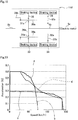
- a transmission it is possible to improve the accelerating performance and high-speed performance. More specifically, by providing a transmission, the relationship between the traveling speed and acceleration of an automobile is close to that of a gasoline engine automobile in which a transmission is provided in the power train, and smooth driving is possible. This will be explained with reference to FIG. 19 .
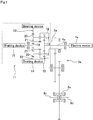
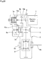
- FIG. 20 illustrates an example of conventional construction of a drive apparatus for an electric automobile in which a transmission is provided between the output shaft of the electric motor and the input section of a differential gear that is connected to the drive wheels, as disclosed in JP 2006-022879 (A ).
- This drive apparatus for an electric automobile is constructed so as to rotate and drive a pair of left and right drive wheels by transmitting the rotation of the output shaft of an electric motor 1 to a rotation transmission apparatus 3 by way of a transmission 2.
- the transmission 2 there is a pair of gear transmission mechanisms 6a, 6b that are located between a drive-side rotating shaft 4 that is concentric with the output shaft of the electric motor 1 and a driven-side rotating shaft 5, and these gear transmission mechanisms 6a, 6b have different reduction ratios.
- one clutch mechanisms 7a of these clutch mechanisms 7a, 7b can be controlled by an actuator, while the other clutch mechanism 7b is an overrunning clutch that becomes disengaged when the rotational speed becomes a fixed value or greater.
- the one clutch mechanism 7a When the one clutch mechanism 7a is engaged, the other clutch mechanism 7b becomes disengaged, and the rotation torque of the drive-side rotating shaft 4 is transmitted to the driven-side rotating shaft 5 by way of the gear transmission mechanism 6a of the gear transmission mechanisms 6a, 6b that has a small reduction ratio.
- the one clutch mechanism 7a is disengaged, the other clutch mechanism 7b becomes engaged, and the rotation torque of the drive-side rotating shaft 4 is transmitted to the driven-side rotating shaft 5 by way of the other gear transmission mechanism 6b having a large reduction ratio.
- the rotation of the driven-side rotating shaft 5 is transmitted to the input section of the differential gear 8 by a rotation transmission apparatus 3, and as a result, the output shafts 9a, 9b that support the pair of left and right drive wheels are rotated and driven.
- a pair of gear transmission mechanisms 6a, 6b are provided between the drive-side rotating shaft 4 and driven-side rotating shaft 5 so as to be separated in the radial direction and parallel with each other.
- the gear transmission mechanism 6a (6b) transmits power by engagement of a gear 10a (10b) that is provided in the middle section in the axial direction of the drive-side rotating shaft 4 and a gear 10c (10d) that is provided in the middle section in the axial direction of the driven-side rotating shaft 5. Therefore, the gears 10a, 10c (10b, 10d), which engage with each other, must have sufficient strength and durability so as to be able to transmit all of the power that is outputted from the electric motor 1. Therefore, there is a problem in that the drive apparatus for an electric automobile in which gear transmission mechanisms 6a, 6b are assembled becomes large and the weight increases.
- the one clutch mechanism 7a requires an actuator for switching the engaged and disengaged (engagement) state.
- the one clutch mechanism 7a is provided in the middle section in the axial direction of the drive-side rotating shaft 4, and with the drive-side rotating shaft 4 in a rotating state, must switch between the engaged and disengaged state of the gear of one gear transmission mechanism 6a of the pair of the gear transmission mechanism 6a, 6b (between state in which the drive-side rotating shaft 4 and gear 10a rotate in synchronization, and state in which the gear 10a idles with respect to the drive-side rotating shaft 4). Therefore, an electromagnetic clutch is used as the one clutch mechanism 7a, so there is a possibility that the construction of the drive apparatus for an electric automobile will become complex. Moreover, in this case, it also becomes difficult to maintain the torque transmission capacity.
- JP 2010-090947 (A ) and JP 2010-223298 (A ) disclose technology in which rotating shafts that are connected to a transmission and that have different reduction ratios from each other are provided on both the inner-diameter side and outer-diameter side of the tube shaped output shaft of an electric motor so as to be concentric with the output shaft, where one rotating shaft of the inner-diameter-side rotating shaft and outer-diameter-side rotating shaft is rotated and driven by a pair of clutches.
- Fig.1 of JP2004-249943 discloses, in the opinion of the examining division of the European Patent Office, a drive apparatus comprising the features of the pre-characterizing portion of claim 1.
- JP2005-180507 discloses a shift fork actuator having a screw-nut mechanism driven by a worm gear.
- EP0695892A2 discloses a single actuator for two synchcromesh couplings.
- the object of the present invention is to achieve a drive apparatus for an electric automobile having compact and simple construction, and that is capable of improving the convenience of an electric automobile by lengthening the distance traveled per charge.
- the inventors investigated construction that uses a planetary-gear transmission as a transmission that is assembled in the drive apparatus for an electric automobile.
- design of a planetary-gear mechanism for obtaining performance equivalent to that of a gasoline engine automobile in which a typical transmission is installed is difficult by simply using a planetary-gear mechanism as the transmission.
- a clutch mechanism is necessary for switching between a state of directly transmitting power between a drive-side rotating shaft and driven-side rotating shaft with these rotating shafts in a state of rotation, so there is a problem in that construction of the apparatus becomes complex, or the planetary-gear mechanism itself becomes large. Therefore, the inventors further investigated construction that uses a planetary-gear mechanism, and were able gain knowledge for solving the problem above by devising construction of a planetary-gear mechanism that led to the completion of the present invention.
- the drive apparatus for an electric automobile of the present invention includes: an electric motor having an output shaft; a planetary-gear transmission having a drive-side rotating shaft that is rotated and driven by the output shaft of the electric motor and a driven-side rotating shaft; and a rotation transmission apparatus for transmitting the rotation of the driven-side rotating shaft of the planetary-gear transmission to a pair of left and right drive wheels.
- the planetary-gear transmission has the drive-side rotating shaft, and the driven-side rotating shaft, as well as a first planetary-gear mechanism, a second planetary-gear mechanism, a ring gear, a first braking device and a second braking device.
- the first planetary-gear mechanism is a single-pinion planetary-gear mechanism that has a first sun gear that is provided so as to be rotated and driven by the drive-side rotating shaft, a plurality (for example, 3 or 4) of first planet gears that engage with the first sun gear, and a carrier that supports the first planet gears so as to be able to rotate and rotates and drives the driven-side rotating shaft.
- the second planetary-gear mechanism is a double-pinion planetary-gear mechanism that has a second sun gear, a plurality of second planet gears that are provided on the outer-diameter side and concentric with the first planet gears, and that rotate in synchronization with the first planet gears, the same number of third planet gears as the second planet gears, that are provided on the inner-diameter side and engage with the second sun gear, and a carrier that is common with that of the first planetary-gear mechanism, in which the carrier supports the second planet gears and third planet gears so as to be able to rotate freely, and in a state in which the second planet gears and third planet gears engage with each other to form a pair.
- the ring gear engages with the first planet gears or the second planet gears.
- the first braking device switches the ring gear and the second braking device switches the second sun gear respectively between a state in which rotation with respect to a fixed portion, such as a casing that houses the planetary-gear transmission, is prevented, and a state in which rotation with respect to the fixed portion is allowed.
- a fixed portion such as a casing that houses the planetary-gear transmission
- the first braking device prevents the rotation of the ring gear with respect to the fixed portion
- the second braking device is released, allowing the second sun gear to rotate with respect to the fixed portion.
- the first braking device is released, allowing the ring gear to rotate with respect to the fixed portion, and the second braking device prevents the second sun gear from rotating with respect to the fixed portion.
- the drive apparatus for an electric automobile further includes, in order to switch the operating states of the first braking device and second braking device, an electric actuator having a piston, a servo motor and a worm wheel is used.
- the piston has a male screw section around the outer circumferential surface of part in the axial direction thereof, and is located inside a casing that houses the planetary-gear transmission so as to be able to displace in the axial direction with rotation prevented.
- the servo motor has an output shaft and a worm gear that is supported by and fastened to the output shaft.
- the worm wheel is formed into a ring shape and engages with the worm gear, and has a female screw section formed around the inner circumferential surface thereof that engages with the male screw section.
- the piston has a first piston having a first male screw section and a second piston having a second male screw section, the first and second male screw sections respectively formed around the outer circumferential surface of the base end section in the axial direction thereof and cut in opposite directions to each other.
- the inner circumferential surface of the worm wheel is a stepped cylindrical surface having a large-diameter section on half in the axial direction and a small-diameter section on the other half in the axial direction that are continuous by way of a stepped section, a first female screw section that engages with the first male screw section is provided on the large-diameter section, and a second female screw section that engages with the second male screw section is provided on the small-diameter screw section.
- the first braking device and second braking device are placed on the same side in the axial direction with respect to the piston, the tip end surface of the first piston faces a first friction engaging section that is formed on the ring gear or a portion that rotates in synchronization with the ring gear, and the tip end surface of the second piston faces a second friction engaging section that is formed on the second sun gear or a portion that rotates in synchronization with the second sun gear.
- the first piston displaces in a direction that causes the tip end section in the axial direction of the first piston to press the first friction engaging section toward the fixed portion
- the second piston displaces in a direction that releases the force by which the tip end section of the second piston presses the second friction engaging section toward the fixed portion.
- the first piston displays in a direction that releases the force by which the tip end section in the axial direction of the first piston presses the first friction engaging section toward the fixed portion
- the second piston displaces in a direction that causes the tip end section of the second piston to press the second friction engaging section toward the fixed portion.
- the step ratio which is a value obtained by dividing the reduction ratio of the planetary-gear transmission in the low-speed mode state by the reduction ratio in the high-speed mode thereof, may be 2 or close to 2, more specifically may be within the range of 1.8 to 2.2, preferably is 2.
- the reduction ratio is a value obtained by dividing the absolute value of the rotating torque of the driven-side rotating shaft by the output torque of the electric motor in each state, which is calculated assuming that there is no friction loss, and that the transmission efficiency is 100%.
- the actuator for switching the operating states of the first braking device and second braking device of the drive apparatus for an electric automobile of the present invention is an electric type having a servo motor as the driving source, instead of construction in which the piston is caused to displace in the axial direction by the engagement between male screw sections on the piston such as described above and the female screw section of the worm wheel, it is possible to employ ball-screw mechanism in which a plurality of balls are provided between an outer-diameter side helical ball-screw groove having a partial arc shape in cross section that is formed around the inner circumferential surface of the worm wheel, and an inner-diameter side helical ball-screw groove having a partial arc shape in cross section that is formed around the outer circumferential surface of the piston so as to be able to roll freely.
- the electric type actuator converts the rotational driving force of the servo motor to thrust force in the axial direction, and this thrust force in the axial direction causes relative displacement of friction engaging section of an opposing member to move toward a fixed portion, and presses the opposing member against the fixed portion to create friction engagement between the fixed portion and the opposing member, preventing rotation of the opposing member with respect to the fixed portion.
- the drive apparatus for an electric automobile of the present invention has a planetary-gear transmission that has a drive-side rotating shaft that is rotated and driven by an output shaft of an electric motor, and a driven-side rotating shaft that transmits rotation to a rotation transmission apparatus for transmitting rotation to a pair of left and right drive wheels; wherein this planetary-gear transmission has a single-pinion first planetary-gear mechanism that is connected to the drive-side rotating shaft, and a double-pinion second planetary-gear mechanism in which one of two planet gears forms a long pinion gear with a planet gear of the first planetary-gear mechanism, and is constructed such that the transmission of power from the second planetary-gear mechanism to the driven-side rotating shaft is by way of the revolution of one of the two planet gears of the second planetary-gear mechanism, and where by switching between the planet gears that revolve for transmitting this power, it is possible to switch between a low-speed mode having a large reduction ratio and a high-speed mode having a small reduction ratio.
- the operating mode is switched between a mode in which the rotation of the sun gear of the first planetary-gear mechanism is transmitted to the driven-side rotating shaft by way of rotation of the planet gears of the first planetary-gear mechanism, rotation of the one planet gear of the second planetary-gear mechanism and revolution of this one planet gear, and the carrier that is connected to this one planet gear, and a mode in which the rotation of the sun gear of the first planetary-gear mechanism is transmitted to the driven-side rotating shaft by way of rotation of the planet gears of the first planetary-gear mechanism, rotation of the one planet gear of the second planetary-gear mechanism, rotation of the other planet gear of the second planetary-gear mechanism and revolution of this other planet gear, and the carrier that is connected to that other planet gear.
- a planetary-gear transmission that comprises a pair of planetary-gear mechanisms is used as the transmission apparatus, so it is possible to divide and transmit the power among a plurality of planet gears, and thus the torque transmission capacity per one planet gear of the pair of planetary-gear mechanisms is kept low.
- the number of planet gears of each of the pair of planetary-gear mechanisms (the number of each of the first planet gears, second planet gears and third planet gears) is taken to be 3 to 4
- the power that is applied to one planet gear is about three out of ten of the total power that is transmitted by the planetary-gear transmission.
- the power transmitted per one planet gear be about three out of ten of the maximum total power transmitted by planetary-gear transmission.
- the first sun gear, second sun gear and ring gear transmit power through engagement with the planet gears at a plurality of locations. Therefore, the strength and rigidity required for the teeth of these gears can be kept low compared with the case of transmitting power by engagement between a pair of gears that engage with each other at only one location, and thus it is possible to make the drive apparatus for an electric automobile more compact and lightweight.
- switching the reduction ratio is performed by switching the second sun gear and the ring gear between a state in which the rotation with respect to a fixed portion is prevented, and a state in which the rotation with respect to the fixed portion is allowed using a pair of braking devices.
- the rotating bodies for example, rotating shafts, and gears provided in the middle sections in the axial direction of the rotating shafts
- the drive apparatus for an electric automobile in which a planetary-gear transmission is assembled even more compact and simple.
- the step ratio which is a value obtained by dividing the reduction ratio in the low-speed mode state by the reduction ratio in the high-speed mode state, 2 or close to 2
- the ratio between the maximum rotational speed in the state of maximum torque output and the overall maximum rotational speed of the motor is about 1:2.
- the ratio between the maximum rotational speed in the state of maximum torque output and the overall maximum rotational speed be 1:4.
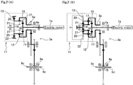
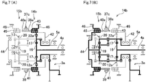
- FIG. 1 to FIG. 2B illustrate a first example of an embodiment of the present invention.
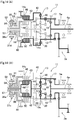
- the drive apparatus for an electric automobile of this example has an electric motor 1a, a planetary-gear transmission 11 and a rotation transmission apparatus 3a.
- the electric motor 1a by way of the output shaft thereof, rotates and drives a drive-side rotating shaft 4a of the planetary-gear transmission 11 that is concentric with the output shaft.
- the planetary-gear transmission 11 is located between the electric motor 1a and the rotation transmission apparatus 3a, and after reducing the power of the electric motor 1a by a specified reduction ratio, transmits that power to the rotation transmission apparatus 3a by way of a hollow tube shaped driven-side rotating shaft 5a.
- the planetary-gear transmission 11 comprises a drive-side rotating shaft 4a and driven-side rotating shaft 5a that are concentric with the output shaft of the electric motor 1a, a first planetary-gear mechanism 12 and second planetary-gear mechanism 13, a ring gear 22, a first braking device 14 and a second braking device 15.
- the first planetary-gear mechanism 12 comprises a first sun gear 16, a plurality (for example, three to four) of first planet gears 17, and a carrier 18.
- the fist planetary-gear mechanism 12 has single-pinion construction in which the first planet gears 17 that are supported by the carrier 18 so as to be able to rotate, are caused to engage with the first sun gear 16.
- the first sun gear 16 is provided on the end section (left end section in FIG. 1 ) of the drive-side rotating shaft 4a, and is rotated and driven by the drive-side rotating shaft 4a.
- a speed reducer such as a friction-roller reducer between the electric motor 1a and the drive-side rotating shaft 4a of the planetary-gear transmission 11. By installing this kind of speed reducer, it is possible to use a compact and high-rpm electric motor and perform control so as to efficiently keep the operating speed of the planetary-gear transmission 11 at a proper value.
- the second planetary-gear mechanism 13 comprises a second sun gear 19, a plurality (same number as the number of first planet gears) of second planet gears 20 that are provided on the outer-diameter side concentric with the first planet gears 17 and that rotate in synchronization with the first planet gears 17, the same number of third planet gears 21 as second planet gears 20, and a carrier 18 that is common with the first planet gears.
- the second planetary-gear mechanism 13 has double-pinion construction in which together with causing the pair of second planet gears 20 and third planet gears 21, which are supported by the carrier 18 so as to be able to rotate, to engage with each other, causes the third planet gears 21 to engage with the second sun gear 19.
- the pitch diameter and number of teeth of the first planet gears 17 and second planet gears 20 is the same, and by providing these gears so as to be continuous (integrated) in the axial direction, a long pinion gear is formed.
- the carrier 18 is provided so as to transmit power to the driven-side rotating shaft 5a. In other words, the driven-side rotating shaft 5a is rotated and driven by the rotation of the carrier 18.
- the ring gear 22 engages with the outer-diameter side second planet gears 20.
- the first braking device 14 is provided between the ring gear 22 and the fixed portion (not illustrated in the figure) of the casing in which the transmission is housed.
- the first braking device 14 controls the actuator such that, by switching the operating (disengaged and engaged) state of the first braking device 14, the ring gear 22 is switched between a state of being prevented from rotating with respect to the fixed portion, and a state of being allowed to rotate (idle).
- the second braking device 15 is provided between the second sun gear 19 and the fixed portion, and controls the actuator such that, by switching the operating (disengaged and engaged) state of the second braking device 15, the second sun gear 19 is switched between a state of being prevented from rotating with respect to the fixed portion, and a state of being allowed to rotate (idle).
- the construction of the actuator that is used in the first braking device 14 and second braking device 15 is not particularly specified. In other words, not only can a mechanical actuator be used, but a hydraulic actuator or electric actuator can also be used.
- the rotation transmission apparatus 3a is a typical gear transmission in which a plurality of gears are combined, and is constructed such that the rotation of the driven-side rotating shaft 5a of the planetary-gear transmission 11 is transmitted to the input section of a differential gear 8a, and a pair of left and right drive wheels are rotated and driven by the output shafts 9c, 9d of the differential gear 8a by way of a universal joint.
- the first braking device 14 is in the engaged state, rotation of the ring gear 22 is prevented, the second braking device 15 is in the disengaged state and rotation of the second sun gear 19 is allowed (the second sun gear 19 idles), and thus the low-speed mode state is achieved.
- the first braking device 14 is released, and the second braking device 15 operates.
- the first braking device 14 is in the disengaged state, the ring gear 22 is allowed to rotate (the ring gear 22 idles), the second braking device 15 is in the engaged state and rotation of the second sun gear 19 is prevented, and thus the high-speed mode is achieved.
- the power from the electric motor 1a that is transmitted to the first planet gears 17 by way of the first sun gear 16 is transmitted to the carrier 18 by way of the second planet gears 20 that revolve while rotating due to the engagement with the ring gear 22.
- the second planet gears 20 that revolve while rotating due to engagement with the ring gear 22 having a large pitch diameter and a large number of teeth it is possible to increase the reduction ratio of the planetary-gear transmission 11.
- the power from the electric motor 1a that is transmitted to the first planet gears 17 by way of the first sun gear 16 is transmitted to the carrier 18 by way of the third planet gears 21 that revolve while rotating due to engagement with the second sun gear 19.
- the reduction ratio of the planetary-gear transmission 11 becomes small.
- the step ratio I between the low-speed mode state and the high-speed mode state (the value obtained by dividing reduction ratio in low-speed mode state by reduction ratio in the high-speed mode state) is 2 or close to 2.
- the reduction ratio in the low-speed mode state and the reduction ratio in the high-speed mode state are expressed by Equations 1 and 2 respectively, so the step ratio I is expressed by the following Equation 3.
- I Z 16 + Z 22 Z 16 + Z 19
- the step ratio I in the planetary-gear transmission 11 of the drive apparatus for an electric automobile of this example is 2 or close to 2.
- the planetary-gear transmission 11 is designed so that the step ratio is 2.
- the value is not strictly 2, but is close to 2
- the same level of operating performance as that of a gasoline engine automobile having a typical transmission can be obtained.
- the case in which the step ratio I is within the range 1.8 to 2.2 is included in the present invention.
- the reduction ratio i L in the low-speed mode, the reduction ratio i H in the high-speed mode and the step ratio I that are found from Equation 1 to Equation 3 are as given below.
- a planetary-gear transmission 11 that has a pair of planetary gear mechanisms as the transmission mechanism is used, and the power is divided and transmitted among a plurality of planet gears 17, 20, 21 so the torque transmitted per one of these planet gears (torque transmission capacity) is kept low.
- the first sun gear 16 transmits power through the engagement in a plurality of locations with the first planet gears 17, the ring gear 22 transmits power through the engagement in a plurality of locations with the second planet gears 20, and the second sun gear 19 transmits power through engagement in a plurality of locations with the third planet gears 31. Therefore, the strength and rigidity that are required for the teeth of the first sun gear 16, second sun gear 19 and ring gear 22 can be kept lower than that of the case of transmitting power though engagement at only one located by a pair of gears 10a, 10c (10b, 10d) as in the conventional construction. As a result, when compared with the case of using a transmission mechanism using a typical gear mechanism, it is possible to make the transmission mechanism more compact and lightweight.
- the planetary-gear transmission 11 selects the low-speed mode or high-speed mode having different reduction ratios by controlling the first braking device 14 and second braking device 15 in order to switch whether or not rotation of the ring gear 11 and second sun gear 19 will be allowed.
- these braking devices switch whether or not rotation of the second sun gear 19 and ring gear 22 will rotate with respect to a portion (fixed portion) that is also stationary, and do not have to switch whether or not there is relative rotation between rotating members (rotating shaft and gears) as in the conventional construction.
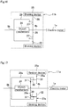
- FIG. 3 illustrates a second example of an embodiment of the present invention.
- the planetary-gear transmission 11a of the drive apparatus for an electric automobile of this example causes a ring gear 22a to engage with first planet gears 17 of a single-pinion first planetary-gear mechanism 12a.
- the construction and function of other parts are the same as in the first example of an embodiment.
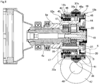
- FIG. 4 to FIG. 5 illustrates a third example of an embodiment of the present invention.
- electric type actuators 37a, 37b that convert the rotating drive force of the servo motor to thrust in the axial direction are used as actuators for switching the operating state of the first braking device 14a and second braking device 15a.
- the actuators 37a, 37b have a servo motor (not illustrated in the figure), a piston 38 and worm wheel 39.
- the piston 38 has a male screw section 40 around the outer circumferential surface of the middle section in the axial direction, and with rotation prevented, is supported inside the casing that houses the planetary-gear transmission 11a such that only displacement in the axial direction is possible.
- the worm wheel 39 engages with a worm gear (not illustrated in the figure) that is supported by and fastened to the output shaft of the servo motor, the entire worm wheel 39 having a circular ring shape, and with displacement in the axial direction prevented, is supported inside the casing so that only rotation is possible. Furthermore, a female screw section 41 that engages with the male screw section 40 is formed around the inner circumferential surface of the worm wheel 41.
- the actuators 37a, 37b are provided in the middle section in the axial direction of the planetary-gear transmission 11a, so the piston 38 is cylindrical shaped, and the members of the planetary-gear transmission 11a are placed on the inner-diameter side thereof.
- the piston of the actuator can be column shaped.
- the output shaft of the servo motor rotates in a specified direction and rotates and drives the worm wheel 39.
- the tip end section of the piston 38 presses a first friction engaging section 43, which is a rotating-side friction plate of a multi-plate wet clutch, that is provided in a first rotating member 42 that is supported so as to be able to rotate in synchronization with the ring gear 22a (or a second friction engaging section 45, which is a rotating friction plate of a multi-plate wet clutch, that is provided in a second rotating member 44 that is supported so as to be able to rotate in synchronization with the second sun gear 19), against a fixed portion 46 (left in FIGS.
- a control unit (not illustrated in the figure) allows the servo motor of one actuator 37a of the actuators 37a, 37b to rotate in a specified direction, and prevents rotation of the ring gear 22a with respect to the fixed portion 46, allows the servo motor of the other actuator 37b to rotated in the opposite direction of the specified direction and allows rotation of the second sun gear 19.
- a control unit allows the servo motor of one actuator 37a of the actuators 37a, 37b to rotate in a specified direction, and prevents rotation of the ring gear 22a with respect to the fixed portion 46, allows the servo motor of the other actuator 37b to rotated in the opposite direction of the specified direction and allows rotation of the second sun gear 19.
- the control unit allows the servo motor of one actuator 37a to rotate in the opposite direction of the specified direction, allows rotation of the ring gear 22a, allows the servo motor of the other actuator 37b to rotate in the specified direction, and prevents rotation of the second sun gear 19.
- rotation of the output shaft of the servo motor is converted to thrust in the axial direction of the piston 38 due to the engagement between the worm gear, which is supported by and fastened to the output shaft, and the worm wheel 39, and engagement between the male screw section 40 of the piston 38 and the female screw section 41 of the worm wheel 39.
- the thrust force in the axial direction causes the tip end surface of the piston 38 to press the first friction engaging section 43 (or second friction engaging section 45) against the fixed portion 46, causing friction engagement between the first friction engaging section 43 (or second friction engaging section 45) and the fixed portion 46.
- a ball-screw mechanism is formed in which an outer-diameter helical ball-screw groove having a partial arc-shaped cross-sectional shape is formed around the inner circumferential surface of a worm wheel, and a helical ball-screw groove having a partial arc-shaped cross-sectional shape is formed around the outer circumferential surface of a piston, and a plurality of balls is provided between these grooves so as to be able to roll freely.
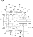
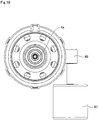
- FIG. 6 to FIG. 12 illustrate a fourth example of an embodiment of the present invention.
- construction is such that the operating state of the first braking device 14b and second braking device 15b is switched by a single actuator 37c. Therefore, the actuator 37c of this example has a male screw section 40a that is provided around the outer circumferential surface of the middle section in the axial direction of the piston 38a.
- This male screw section 4a engages with a female screw section 41 that is provided around the inner circumferential surface of the worm wheel 39.
- a first braking device 14b and second braking device 15b are located on opposite sides in the axial direction from each other with respect to the actuator 37c. Therefore, the first friction engaging section 43 and second friction engaging section 45 of the first braking device 14b and second braking device 15b face both end surfaces in the axial direction of the piston 38a.
- the drive apparatus for an electric automobile of this example When operating in the low-speed mode state having a large reduction ratio, the drive apparatus for an electric automobile of this example, as illustrated in FIG. 12A , rotates the output shaft of the servo motor 47 in a specified direction (clockwise direction in FIG. 12A ), and rotates and drives a worm wheel 39 due to the engagement with a worm gear 48 that supported by and fastened to the output shaft of the servo motor 47.
- the piston 38a displaces due to the engagement between the male screw section 40a and the female screw section 41, in a direction (right direction in FIG. 12A ) such that one end section (right end section in FIG.
- the first friction engaging section 43 has a friction fit with the fixed portion 46, and together with preventing rotation of the ring gear 22a, allows rotation of the second sun gear 19.
- the drive apparatus for an electric automobile of this example when operating in the high-speed mode state having a small reduction ratio, rotates the output shaft of the servo motor 47 in the opposite direction of the specified direction (counterclockwise direction in FIG. 12B ), and rotates and drives the worm wheel 39.
- the piston 38a displaces due to the engagement between the male screw section 40a and the female screw section 41, which releases the force by which the one end section in the axial direction of the piston 38a presses the first friction engaging section 43 against the fixed portion 46, and causes the other end section in the axial direction of the piston 38a to press the second friction engaging section 45 against the fixed portion 46.
- there is a friction fit between the second friction engaging section 45 and the fixed portion 46 which, together with preventing rotating of the second sun gear 19, allows rotation of the ring gear 22a.
- the drive apparatus for an electric automobile of this example With the drive apparatus for an electric automobile of this example, the operating state of the first braking device 14b and second braking device 15b can be switched by a single actuator 37c. Therefore, the drive apparatus for an electric automobile can have more compact and simple construction than in the case of the third example of an embodiment, and it is possible to further improve the convenience of an electric automobile.
- the construction and functions of other parts of this example are the same as in the second and third examples of an embodiment.
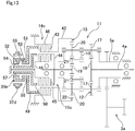
- FIG. 13 to FIG. 15 illustrate a fifth example of an embodiment of the present invention.
- This example as well, as in the fourth example of an embodiment, is constructed such that the first braking device 14c and second braking device 15c are switched by a single actuator 37d.
- the actuator 37d in this example has a servo motor (not illustrated in the figure), a first piston 49, a second piston 50, and a worm wheel 39a.
- the first piston 49 and second piston 50 have a first male screw section 51 and a second male screw section 52 that are formed around the outer circumferential surface of the base end sections in the axial direction thereof (left end section in FIG. 13 to FIG 15 ) such that the screw directions are in opposite directions from each other.
- the worm wheel 39a the inner circumferential surface thereof being a stepped cylindrical surface having a large-diameter section 53 in one half section (right half section in FIG. 13 to FIG. 15 ) in the axial direction and a small-diameter section 54 in the other half section (left half section in FIG. 13 to FIG. 15 ) in the axial direction that are continuous by way of a stepped section 55.
- a first female screw section 56 that engages with the first male section 51 is formed in the large-diameter section 53
- a second female screw section 57 that engages with the second male screw section 52 is formed in the small-diameter section 54.
- the first braking device 14c and second braking device 15c are placed on the same side as each other in the axial direction with respect to the actuator 37d, and the first friction engaging section 43 and second friction engaging section 45 of the first braking device 14c and second braking device 15c face the tip end surfaces of the first piston 49 and second piston 50, respectively. Therefore, the first piston 49 has a cylindrical shape, and with the middle section and tip end section in the axial direction of the second piston 50 inserted into the inner-diameter side thereof, the first male screw section 51 engages with and is supported by the female screw 56.
- the drive apparatus for an electric automobile of this example When operating in the low-speed mode state having a large reduction ratio, the drive apparatus for an electric automobile of this example, as illustrated in FIG. 15A , rotates the output shaft of the servo motor in a specified direction (clockwise direction in FIG. 15A ), and rotates and drives the worm wheel 39a.
- the first piston 49 displaces in the axial direction due to engagement between the male screw section 51 and the female screw section 56, and the tip end section (right end section in FIG. 15A ) of the first piston 49 presses the first friction engaging section 43 toward the fixed portion 46 (displaces toward the right in FIG. 15A ).
- the drive apparatus for an electric automobile When operating in the high-speed mode state having a small reduction ratio, the drive apparatus for an electric automobile, as illustrated in FIG. 15B , rotates the output shaft of the servo motor in the opposite direction of the specified direction (counterclockwise direction of the FIG. 15B ), and drives and rotates the worm wheel 39a.
- the first piston 49 displaces in a direction (left in FOG. 15B) that releases the force by which the tip end section of the first piston 49 presses the first friction engaging section 43 toward the fixed portion 46.
- the second piston 47 displaces in a direction (displaces toward the right in FIG.
- the operating state of the first braking device 14c and the second braking device 15c can be switched by a single actuator 37d, so convenience of an electric automobile is further improved.
- the first braking device 14c and the second braking device 15c are arranged in a portion adjacent in the axial direction to the first planetary-gear mechanism 12 and second planetary-gear mechanism 13 of the planetary-gear transmission 11.
- first braking device 14c and the second braking device 15c are constructed such that, by causing the first friction engaging section 43 and second friction engaging section 45, which are respectively provided on the first rotating member 42 and second rotating member 44 that rotate in synchronization with the ring gear 22 and second sun gear 19, to displace in the axial direction relative to the fixed portion 46, perform switching whether to allow or not allow rotation of the ring gear 22 and second sun gear 19.
- the outer diameter of the first braking device 14c and the second braking device 15f is suppressed so as to be equal to or less than the outer diameter of the first planetary gear mechanism 12 and second planetary gear mechanism 13, and thus the drive apparatus for an electric automobile can be made even more compact.
- the construction and functions of the other parts of this example are the same as in the first, third and fourth example of an embodiment of the present invention.
- FIG. 16 illustrates a first reference example for a comparison with the present invention.
- a planetary-gear mechanism is used for the transmission that is assembled in the drive apparatus for an electric automobile.
- the planetary-gear transmission 11b has a drive-side rotating shaft 4b that is rotated and driven by the output shaft of the electric motor 1a, a driven-side rotating shaft 5b, a clutch mechanism 24, and a braking device 25.
- the driven-side rotating shaft 5b is provided so as to be concentric with the drive-side rotating shaft 4b, the rotation thereof being transmitted to the input section of a differential gear 8 by way of a rotation transmission 3 (see FIG. 20 ).
- the planetary-gear mechanism 23 has a sun gear 26, a plurality of planet gears 27, a ring gear 28 and a carrier 29, and has single-pinion construction in which the planet gears 27, which are supported by the carrier 29 so as to be able to rotate, engage with the sun gear 26 as well as engage with the ring gear 28.
- the sun gear 26 is provided in the middle section in the axial direction of the drive-side rotating shaft 4b, and is rotated and driven by the drive-side rotating shaft 4b.
- the carrier 29 is supported so as to transmit power to the driven-side rotating shaft 5b.
- the clutch mechanism is provided between the drive-side rotating shaft 4b and the driven-side rotating shaft 5b, and makes it possible to switch between a state in which power can be transmitted, and a state in which power is not transmitted.
- the braking device 25 is provided between the ring gear 28 and a fixed portion such as casing, and makes it possible to switch between a state in which rotation of the ring gear 28 with respect to the fixed portion is allowed, and a state in which that rotation is not allowed.
- This kind of planetary-gear transmission 11b by switching the operating (disengaged and engaged) state of the clutch mechanism 24 and braking device mechanism 25, operates in a low-speed mode state having a large reduction ratio between the drive-side rotating shaft 4b and the driven-side rotating shaft 5b, or a high-speed mode state having a small reduction ratio.
- the low-speed mode is achieved by disengaging the clutch mechanism 24 so that power cannot be directly transmitted between the drive-side rotating shaft 4b and the driven-side rotating shaft 5b, and engaging the braking device 25 so that rotation of the ring gear 28 with respect to the fixed portion is prevented.
- Equation 4 The reduction ratio i L1 of the planetary-gear transmission 11b in the low-speed mode is expressed by Equation 4 below in which the number of teeth of the sun gear 26 is taken to be Z 26 , and the number of teeth of the ring gear 28 is taken to be Z 28 .
- i L 1 Z 26 Z 26 + Z 28
- the high-speed mode is achieved by engaging the clutch mechanism so that the power can be directly transmitted between the drive-side rotating shaft 4b and the driven-side rotating shaft 5b, and disengaging the braking device 25 so that rotation of the ring gear 28 with respect to the fixed portion is allowed.
- the reduction ratio i H1 of the planetary-gear transmission 11b in the high-speed mode is 1 (there is no reduction).
- step ratio 2 or near 2 it is necessary for the number of teeth of the sun gear 26 and the ring gear 28 of the planetary-gear mechanism 23 the same or nearly the same, however, in actuality, such a design is difficult. Therefore, in the drive apparatus for an electric automobile in which the planetary-gear transmission 11b is assembled, it is difficult to improve the accelerating performance and high-speed performance of a vehicle by obtaining equivalent performance as that of a gasoline engine automobile in which a typical transmission is installed.
- FIG. 17 illustrates a second reference example for comparison with the present invention.
- the planetary-gear transmission 11c of this reference example has a drive-side rotating shaft 4b that is provided so as to be concentric with the electric motor 1a, a planetary-gear mechanism 23a, a driven-side rotating shaft 5b, a clutch mechanism 24 and a braking device 25a.
- the planetary-gear mechanism 23a is constructed such that first planet gears 31, which are supported by and fastened to one end section (left end section in FIG.
- the braking device 25a is provided between the ring gear 28a and the fixed portion, and makes it possible to switch between a state in which rotating of the ring gear 28a with respect to the fixed portion is allowed, and a state in which rotation is prohibited.
- the planetary-gear transmission of this reference example switches between a low-speed mode having a large reduction ratio and a high-speed mode having a small reduction ratio by switching the operating state of the clutch mechanism 24 and braking device 25a.
- the reduction ratio i L2 of the planetary-gear transmission 11c in the low-speed mode is expressed by Equation 6 below where the number of teeth of the sun gear 26a is taken to be Z 26a , the number of teeth of the ring gear 28a is taken to be Z 28a , the number of teeth of the first planet gears 31 is taken to be Z 31 , and the number of teeth of the second planet gears 32 is taken to be Z 32 .
- i L 2 Z 26 a Z 32 Z 26 a Z 32 + Z 28 a Z 31
- the reduction ratio i H2 in the high-speed mode is 1 (there is no reduction), so the step ratio I 2 between the low-speed mode and the high-speed mode is as expressed in Equation 7 below.
- I 2 Z 26 a Z 32 + Z 28 a Z 31 Z 26 a Z 32
- the step ratio I 2 can be made to be 2 or close to 2, so in a drive apparatus for an electric automobile in which a planetary-gear transmission 11c is assembled, performance that is equivalent to that of a gasoline engine automobile in which a transmission is installed is obtained, and thus it is possible to improve the accelerating performance and high-speed performance of the vehicle.
- a clutch mechanism 24 for switching between the state in which power is transmitted between the drive-side rotating shaft 4b and the driven-side rotating shaft 5b and the state in which power is not transmitted with the rotating shafts 4b, 5b rotating is necessary, so there is a possibility that construction will be complex.
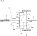
- FIG. 18 illustrates a third reference example for comparison with the present invention.
- the planetary-gear transmission 11d of this reference example has a drive-side rotating shaft 4b, a planetary-gear mechanism 23b, a driven-side rotating shaft 5b, a first braking device 33 and a second braking device 34.
- the planetary-gear mechanism 23b causes first planet gears 31a, which are supported by and fastened to the middle section in the axial direction of a plurality of planet shafts 30a that are supported by a carrier 29b so as to be able to rotate, to engage with both a sun gear 26b, and also a first ring gear 35.
- the planetary-gear mechanism 23b causes second planet gears 32a that are supported by and fastened to the end sections (right end sections in FIG. 18 ) of the planet shafts 30 to engage with a second ring gear 36.
- the first braking device 33 and second braking device 34 make it possible to switch the first ring gear 35 and second ring gear 36 between a state in which rotation with respect to a fixed portion is allowed and a state in which rotation is prohibited.
- the reduction ratio i b in the second mode, in which the first braking device is disengaged, allowing the rotation of the first ring gear 35, and the second braking device 34 is engaged, preventing the rotation of the second ring gear 36 is expressed by Equation 9 below where the number of teeth of the first planet gears 31a, the second planet gears 32a and the second ring gear 36, are taken to be Z 31a , Z 32a and Z 36 , respectively.
- i b Z 26 b Z 32 a Z 31 a Z 36 + Z 26 b Z 32 a
- the reduction ratio i a in the first mode becomes greater than the reduction ratio ib in the second mode (ia > ib).
- the number of teeth Z35, Z36 of the first and second ring gears 35, 36 are expressed by Equations 10 and 11, respectively.
- Z 35 Z 26 b + 2 Z 31 a
- Z 36 Z 26 b + Z 31 a + Z 32 a
- I c 1 2 ⁇ Z 32 a Z 31 a + Z 32 a
- the number of teeth Z 31a of the first planet gears 31a must be about three times the number of teeth Z 32a of the second planet gears 32a (Z 31a ⁇ 3Z 32a ).
- the pitch diameter of the first planet gears 31a and the first ring gear 35 becomes large, and there is a possibility that the planetary-gear transmission 11d will become large.
Landscapes
- Engineering & Computer Science (AREA)
- General Engineering & Computer Science (AREA)
- Mechanical Engineering (AREA)
- Transportation (AREA)
- Power Engineering (AREA)
- Combustion & Propulsion (AREA)
- Chemical & Material Sciences (AREA)
- Structure Of Transmissions (AREA)
- Connection Of Motors, Electrical Generators, Mechanical Devices, And The Like (AREA)
- Arrangement Or Mounting Of Propulsion Units For Vehicles (AREA)
- Gear Transmission (AREA)
- Electric Propulsion And Braking For Vehicles (AREA)
- Retarders (AREA)
Applications Claiming Priority (3)
| Application Number | Priority Date | Filing Date | Title |
|---|---|---|---|
| JP2011236658 | 2011-10-28 | ||
| JP2012224983A JP6028507B2 (ja) | 2011-10-28 | 2012-10-10 | 電気自動車用駆動装置 |
| PCT/JP2012/077516 WO2013062017A1 (ja) | 2011-10-28 | 2012-10-24 | 電気自動車用駆動装置 |
Publications (3)
| Publication Number | Publication Date |
|---|---|
| EP2772665A1 EP2772665A1 (en) | 2014-09-03 |
| EP2772665A4 EP2772665A4 (en) | 2016-10-26 |
| EP2772665B1 true EP2772665B1 (en) | 2018-12-05 |
Family
ID=48167844
Family Applications (1)
| Application Number | Title | Priority Date | Filing Date |
|---|---|---|---|
| EP12843885.0A Not-in-force EP2772665B1 (en) | 2011-10-28 | 2012-10-24 | Electric vehicle driving device |
Country Status (5)
| Country | Link |
|---|---|
| US (1) | US9067491B2 (ja) |
| EP (1) | EP2772665B1 (ja) |
| JP (1) | JP6028507B2 (ja) |
| CN (1) | CN103917803A (ja) |
| WO (1) | WO2013062017A1 (ja) |
Families Citing this family (27)
| Publication number | Priority date | Publication date | Assignee | Title |
|---|---|---|---|---|
| DE102015103584A1 (de) * | 2015-03-11 | 2016-09-15 | Gkn Driveline International Gmbh | Getriebeanordnung und Elektroantrieb mit einer solchen Getriebeanordnung |
| DE102015217521A1 (de) * | 2015-09-14 | 2017-03-16 | Siemens Aktiengesellschaft | Antriebseinrichtung für ein Kraftfahrzeug, insbesondere ein Elektro- oder Hybrid-Fahrzeug |
| JP6533517B2 (ja) * | 2015-09-29 | 2019-06-19 | 日鍛バルブ株式会社 | トルク伝達装置 |
| US9719584B1 (en) * | 2016-05-25 | 2017-08-01 | Guangzhou Sunmile Dynamic Technologies Corp., Ltd | Two-speed transaxle for electric vehicle |
| JP6418218B2 (ja) * | 2016-10-06 | 2018-11-07 | トヨタ自動車株式会社 | 車両用差動制限装置 |
| DE102017004931A1 (de) * | 2016-12-21 | 2018-06-21 | Daimler Ag | Getriebevorrichtung für ein Kraftfahrzeug |
| CN107061642A (zh) * | 2017-03-15 | 2017-08-18 | 清华大学 | 一种双制动器式电动车两档变速箱及其控制方法 |
| KR101909108B1 (ko) * | 2017-04-04 | 2018-12-10 | 주식회사 인팩 | 다단 감속 구동장치 |
| DE102017007081B4 (de) * | 2017-07-27 | 2019-06-06 | Daimler Ag | Elektrische Achsantriebsvorrichtung für ein Kraftfahrzeug, insbesondere für ein Nutzfahrzeug, sowie Kraftfahrzeug mit wenigstens einer solchen elektrischen Achsantriebsvorrichtung |
| CN109795310B (zh) * | 2017-11-17 | 2023-08-11 | 宇通客车股份有限公司 | 一种混合动力系统及使用该混合动力系统的车辆 |
| DE102018211672A1 (de) | 2018-07-12 | 2020-01-16 | Robert Bosch Gmbh | Lastschaltbares Mehrganggetriebe |
| KR102532314B1 (ko) * | 2018-07-30 | 2023-05-16 | 현대자동차주식회사 | 전기차용 변속기 |
| CN108953539A (zh) * | 2018-09-05 | 2018-12-07 | 恒大法拉第未来智能汽车(广东)有限公司 | 两档变速器及电动汽车 |
| CN108843751B (zh) * | 2018-09-19 | 2019-09-06 | 吉林大学 | 一种一体化电驱动系统及其控制方法 |
| CN111376714B (zh) * | 2018-12-29 | 2022-04-15 | 比亚迪股份有限公司 | 电驱减速器、电驱动桥动力总成、车辆 |
| CN111376713B (zh) * | 2018-12-29 | 2021-07-20 | 比亚迪股份有限公司 | 电驱减速器、电驱动桥动力总成、车辆 |
| CN109780146A (zh) * | 2019-03-13 | 2019-05-21 | 重庆德音科技有限公司 | 电动汽车用两挡机械自动变速器 |
| CN110065387A (zh) * | 2019-04-26 | 2019-07-30 | 湖北启源科技有限公司 | 一种电动活塞驱动式电动车及其工作方法 |
| CN114080521A (zh) * | 2019-06-28 | 2022-02-22 | 霍顿公司 | 具有在前进模式和后退模式下运行的行星齿轮传动机构的传动系统 |
| CN112829739B (zh) * | 2019-11-22 | 2023-04-07 | 广州汽车集团股份有限公司 | 混合动力驱动装置的工作模式控制方法和混合动力系统 |
| DE102020112624A1 (de) | 2020-05-11 | 2021-11-11 | Schaeffler Technologies AG & Co. KG | Getriebeeinrichtung für einen elektrischen Antrieb eines Fahrzeuges |
| EP4227550A1 (en) * | 2020-10-09 | 2023-08-16 | NSK Ltd. | Two-speed transmission |
| WO2022176579A1 (ja) | 2021-02-18 | 2022-08-25 | ユニプレス株式会社 | 電気自動車用2段変速機 |
| CN113266672A (zh) * | 2021-05-06 | 2021-08-17 | 恒大新能源汽车投资控股集团有限公司 | 换挡提醒方法、系统及车辆 |
| CN113236731B (zh) * | 2021-05-10 | 2023-01-06 | 柳工柳州传动件有限公司 | 行星变速箱和电动工程机械 |
| WO2023048134A1 (ja) * | 2021-09-24 | 2023-03-30 | 株式会社アイシン | 車両用駆動装置 |
| WO2024070143A1 (ja) * | 2022-09-27 | 2024-04-04 | 株式会社アイシン | 変速機、及びそれを備えた車両用駆動伝達装置 |
Family Cites Families (17)
| Publication number | Priority date | Publication date | Assignee | Title |
|---|---|---|---|---|
| JPS608548A (ja) | 1983-06-25 | 1985-01-17 | Mazda Motor Corp | 自動変速機の変速装置 |
| JPS608548U (ja) * | 1983-06-29 | 1985-01-21 | トヨタ自動車株式会社 | 電気自動車用変速機 |
| US4966267A (en) * | 1989-09-21 | 1990-10-30 | Borg-Warner Automotive Diversified Transmission Products Corporation | Ball screw actuated clutch combination |
| US5517876A (en) * | 1994-08-04 | 1996-05-21 | Eaton Corporation | Transmission spring loaded shift device |
| JP2004249943A (ja) * | 2003-02-21 | 2004-09-09 | Toyota Motor Corp | 車両の駆動装置 |
| JP2005090682A (ja) * | 2003-09-19 | 2005-04-07 | Suzuki Motor Corp | 自動変速機 |
| JP2005180507A (ja) * | 2003-12-17 | 2005-07-07 | Nsk Ltd | 自動変速機用アクチュエータ |
| JP2006022879A (ja) | 2004-07-07 | 2006-01-26 | Gkn ドライブライン トルクテクノロジー株式会社 | 電動モータ駆動装置 |
| JP2009002499A (ja) * | 2007-06-25 | 2009-01-08 | Bunji Koshiishi | 過給機を駆動するトルクを利用したプラネタリギア式自動車発進装置 |
| JP2009250375A (ja) * | 2008-04-08 | 2009-10-29 | Toyota Motor Corp | 車両の駆動装置 |
| JP5568229B2 (ja) | 2008-10-06 | 2014-08-06 | Ntn株式会社 | 電動モータ駆動装置 |
| WO2010041531A1 (ja) * | 2008-10-06 | 2010-04-15 | Ntn株式会社 | 電動モータ駆動装置 |
| JP2010223298A (ja) | 2009-03-23 | 2010-10-07 | Ntn Corp | 電動モータ駆動装置 |
| JP5413719B2 (ja) * | 2009-07-31 | 2014-02-12 | 日立オートモティブシステムズ株式会社 | 電動ブレーキ装置 |
| JP5051476B2 (ja) | 2009-08-10 | 2012-10-17 | アイシン・エィ・ダブリュ株式会社 | 車両用駆動装置 |
| JP2011208681A (ja) * | 2010-03-29 | 2011-10-20 | Jatco Ltd | 車両用減速装置 |
| WO2013046748A1 (ja) * | 2011-09-26 | 2013-04-04 | 日本精工株式会社 | 電気自動車用駆動装置 |
-
2012
- 2012-10-10 JP JP2012224983A patent/JP6028507B2/ja not_active Expired - Fee Related
- 2012-10-24 CN CN201280053031.2A patent/CN103917803A/zh active Pending
- 2012-10-24 EP EP12843885.0A patent/EP2772665B1/en not_active Not-in-force
- 2012-10-24 US US14/354,765 patent/US9067491B2/en not_active Expired - Fee Related
- 2012-10-24 WO PCT/JP2012/077516 patent/WO2013062017A1/ja active Application Filing
Non-Patent Citations (1)
| Title |
|---|
| None * |
Also Published As
| Publication number | Publication date |
|---|---|
| US20140287863A1 (en) | 2014-09-25 |
| JP6028507B2 (ja) | 2016-11-16 |
| JP2013108619A (ja) | 2013-06-06 |
| US9067491B2 (en) | 2015-06-30 |
| WO2013062017A1 (ja) | 2013-05-02 |
| EP2772665A4 (en) | 2016-10-26 |
| CN103917803A (zh) | 2014-07-09 |
| EP2772665A1 (en) | 2014-09-03 |
Similar Documents
| Publication | Publication Date | Title |
|---|---|---|
| EP2772665B1 (en) | Electric vehicle driving device | |
| EP2762747B1 (en) | Electric vehicle drive unit | |
| JP4274268B2 (ja) | 動力伝達装置 | |
| JP4466685B2 (ja) | 車両用動力伝達装置 | |
| JP4763044B2 (ja) | 直結ギヤにおいて切り離し可能なカウンタシャフトを有するトランスミッション | |
| JP2013108619A5 (ja) | ||
| US8882628B2 (en) | Multiple speed transmission | |
| US20230213092A1 (en) | Transmission, drive train and vehicle having a transmission | |
| JP2008174229A (ja) | ハイブリッド電気自動車のパワートレイン | |
| CN113710927A (zh) | 变速器、动力传动系和车辆 | |
| JP2011085255A (ja) | 駆動装置 | |
| CN110030356B (zh) | 一种基于锥齿轮的三档电动汽车自动变速器 | |
| JP2017193320A (ja) | 自動車用駆動装置 | |
| CN109641519A (zh) | 动力输出传动齿轮推力负载抵消 | |
| JP2004278562A (ja) | タンデム型摩擦係合装置 | |
| CN107542863B (zh) | 三行星排混合动力两挡自动变速器总成 | |
| CN114340931A (zh) | 传动装置、驱动系和具有传动装置的车辆 | |
| EP3740701B1 (en) | Gearing assembly and gearing apparatus | |
| JP7428171B2 (ja) | 動力伝達装置 | |
| JP2008057655A (ja) | 多段変速遊星歯車列 | |
| KR101178501B1 (ko) | 무단 변속기의 전후진 변속시스템 | |
| JP2009001120A (ja) | 動力伝達装置 | |
| KR20190115301A (ko) | 후진 제어가 가능한 전기자동차용 변속 시스템 | |
| KR20220097163A (ko) | 감속기 | |
| CN116176257A (zh) | 一种应用于商用车的混合动力变速系统 |
Legal Events
| Date | Code | Title | Description |
|---|---|---|---|
| PUAI | Public reference made under article 153(3) epc to a published international application that has entered the european phase |
Free format text: ORIGINAL CODE: 0009012 |
|
| 17P | Request for examination filed |
Effective date: 20140428 |
|
| AK | Designated contracting states |
Kind code of ref document: A1 Designated state(s): AL AT BE BG CH CY CZ DE DK EE ES FI FR GB GR HR HU IE IS IT LI LT LU LV MC MK MT NL NO PL PT RO RS SE SI SK SM TR |
|
| DAX | Request for extension of the european patent (deleted) | ||
| RIC1 | Information provided on ipc code assigned before grant |
Ipc: H02K 7/116 20060101ALI20160616BHEP Ipc: F16H 3/66 20060101AFI20160616BHEP Ipc: B60K 1/00 20060101ALI20160616BHEP |
|
| RA4 | Supplementary search report drawn up and despatched (corrected) |
Effective date: 20160927 |
|
| RIC1 | Information provided on ipc code assigned before grant |
Ipc: B60K 1/00 20060101ALN20160921BHEP Ipc: H02K 7/116 20060101ALI20160921BHEP Ipc: F16H 3/66 20060101AFI20160921BHEP Ipc: B60L 15/20 20060101ALI20160921BHEP |
|
| GRAP | Despatch of communication of intention to grant a patent |
Free format text: ORIGINAL CODE: EPIDOSNIGR1 |
|
| STAA | Information on the status of an ep patent application or granted ep patent |
Free format text: STATUS: GRANT OF PATENT IS INTENDED |
|
| RIC1 | Information provided on ipc code assigned before grant |
Ipc: F16H 61/28 20060101ALN20180507BHEP Ipc: B60L 15/20 20060101ALI20180507BHEP Ipc: H02K 7/116 20060101ALI20180507BHEP Ipc: F16H 3/66 20060101AFI20180507BHEP Ipc: B60K 17/12 20060101ALI20180507BHEP Ipc: B60K 1/00 20060101ALN20180507BHEP |
|
| INTG | Intention to grant announced |
Effective date: 20180612 |
|
| GRAS | Grant fee paid |
Free format text: ORIGINAL CODE: EPIDOSNIGR3 |
|
| GRAA | (expected) grant |
Free format text: ORIGINAL CODE: 0009210 |
|
| GRAA | (expected) grant |
Free format text: ORIGINAL CODE: 0009210 |
|
| STAA | Information on the status of an ep patent application or granted ep patent |
Free format text: STATUS: THE PATENT HAS BEEN GRANTED |
|
| AK | Designated contracting states |
Kind code of ref document: B1 Designated state(s): AL AT BE BG CH CY CZ DE DK EE ES FI FR GB GR HR HU IE IS IT LI LT LU LV MC MK MT NL NO PL PT RO RS SE SI SK SM TR |
|
| REG | Reference to a national code |
Ref country code: GB Ref legal event code: FG4D |
|
| REG | Reference to a national code |
Ref country code: CH Ref legal event code: EP |
|
| REG | Reference to a national code |
Ref country code: AT Ref legal event code: REF Ref document number: 1073472 Country of ref document: AT Kind code of ref document: T Effective date: 20181215 |
|
| REG | Reference to a national code |
Ref country code: IE Ref legal event code: FG4D |
|
| REG | Reference to a national code |
Ref country code: DE Ref legal event code: R096 Ref document number: 602012054473 Country of ref document: DE |
|
| REG | Reference to a national code |
Ref country code: NL Ref legal event code: MP Effective date: 20181205 |
|
| REG | Reference to a national code |
Ref country code: AT Ref legal event code: MK05 Ref document number: 1073472 Country of ref document: AT Kind code of ref document: T Effective date: 20181205 |
|
| REG | Reference to a national code |
Ref country code: LT Ref legal event code: MG4D |
|
| PG25 | Lapsed in a contracting state [announced via postgrant information from national office to epo] |
Ref country code: FI Free format text: LAPSE BECAUSE OF FAILURE TO SUBMIT A TRANSLATION OF THE DESCRIPTION OR TO PAY THE FEE WITHIN THE PRESCRIBED TIME-LIMIT Effective date: 20181205 Ref country code: BG Free format text: LAPSE BECAUSE OF FAILURE TO SUBMIT A TRANSLATION OF THE DESCRIPTION OR TO PAY THE FEE WITHIN THE PRESCRIBED TIME-LIMIT Effective date: 20190305 Ref country code: LT Free format text: LAPSE BECAUSE OF FAILURE TO SUBMIT A TRANSLATION OF THE DESCRIPTION OR TO PAY THE FEE WITHIN THE PRESCRIBED TIME-LIMIT Effective date: 20181205 Ref country code: NO Free format text: LAPSE BECAUSE OF FAILURE TO SUBMIT A TRANSLATION OF THE DESCRIPTION OR TO PAY THE FEE WITHIN THE PRESCRIBED TIME-LIMIT Effective date: 20190305 Ref country code: ES Free format text: LAPSE BECAUSE OF FAILURE TO SUBMIT A TRANSLATION OF THE DESCRIPTION OR TO PAY THE FEE WITHIN THE PRESCRIBED TIME-LIMIT Effective date: 20181205 Ref country code: AT Free format text: LAPSE BECAUSE OF FAILURE TO SUBMIT A TRANSLATION OF THE DESCRIPTION OR TO PAY THE FEE WITHIN THE PRESCRIBED TIME-LIMIT Effective date: 20181205 Ref country code: HR Free format text: LAPSE BECAUSE OF FAILURE TO SUBMIT A TRANSLATION OF THE DESCRIPTION OR TO PAY THE FEE WITHIN THE PRESCRIBED TIME-LIMIT Effective date: 20181205 Ref country code: LV Free format text: LAPSE BECAUSE OF FAILURE TO SUBMIT A TRANSLATION OF THE DESCRIPTION OR TO PAY THE FEE WITHIN THE PRESCRIBED TIME-LIMIT Effective date: 20181205 |
|
| PG25 | Lapsed in a contracting state [announced via postgrant information from national office to epo] |
Ref country code: SE Free format text: LAPSE BECAUSE OF FAILURE TO SUBMIT A TRANSLATION OF THE DESCRIPTION OR TO PAY THE FEE WITHIN THE PRESCRIBED TIME-LIMIT Effective date: 20181205 Ref country code: AL Free format text: LAPSE BECAUSE OF FAILURE TO SUBMIT A TRANSLATION OF THE DESCRIPTION OR TO PAY THE FEE WITHIN THE PRESCRIBED TIME-LIMIT Effective date: 20181205 Ref country code: RS Free format text: LAPSE BECAUSE OF FAILURE TO SUBMIT A TRANSLATION OF THE DESCRIPTION OR TO PAY THE FEE WITHIN THE PRESCRIBED TIME-LIMIT Effective date: 20181205 Ref country code: GR Free format text: LAPSE BECAUSE OF FAILURE TO SUBMIT A TRANSLATION OF THE DESCRIPTION OR TO PAY THE FEE WITHIN THE PRESCRIBED TIME-LIMIT Effective date: 20190306 |
|
| PG25 | Lapsed in a contracting state [announced via postgrant information from national office to epo] |
Ref country code: NL Free format text: LAPSE BECAUSE OF FAILURE TO SUBMIT A TRANSLATION OF THE DESCRIPTION OR TO PAY THE FEE WITHIN THE PRESCRIBED TIME-LIMIT Effective date: 20181205 |
|
| PG25 | Lapsed in a contracting state [announced via postgrant information from national office to epo] |
Ref country code: IT Free format text: LAPSE BECAUSE OF FAILURE TO SUBMIT A TRANSLATION OF THE DESCRIPTION OR TO PAY THE FEE WITHIN THE PRESCRIBED TIME-LIMIT Effective date: 20181205 Ref country code: PL Free format text: LAPSE BECAUSE OF FAILURE TO SUBMIT A TRANSLATION OF THE DESCRIPTION OR TO PAY THE FEE WITHIN THE PRESCRIBED TIME-LIMIT Effective date: 20181205 Ref country code: PT Free format text: LAPSE BECAUSE OF FAILURE TO SUBMIT A TRANSLATION OF THE DESCRIPTION OR TO PAY THE FEE WITHIN THE PRESCRIBED TIME-LIMIT Effective date: 20190405 Ref country code: CZ Free format text: LAPSE BECAUSE OF FAILURE TO SUBMIT A TRANSLATION OF THE DESCRIPTION OR TO PAY THE FEE WITHIN THE PRESCRIBED TIME-LIMIT Effective date: 20181205 |
|
| PG25 | Lapsed in a contracting state [announced via postgrant information from national office to epo] |
Ref country code: EE Free format text: LAPSE BECAUSE OF FAILURE TO SUBMIT A TRANSLATION OF THE DESCRIPTION OR TO PAY THE FEE WITHIN THE PRESCRIBED TIME-LIMIT Effective date: 20181205 Ref country code: IS Free format text: LAPSE BECAUSE OF FAILURE TO SUBMIT A TRANSLATION OF THE DESCRIPTION OR TO PAY THE FEE WITHIN THE PRESCRIBED TIME-LIMIT Effective date: 20190405 Ref country code: RO Free format text: LAPSE BECAUSE OF FAILURE TO SUBMIT A TRANSLATION OF THE DESCRIPTION OR TO PAY THE FEE WITHIN THE PRESCRIBED TIME-LIMIT Effective date: 20181205 Ref country code: SK Free format text: LAPSE BECAUSE OF FAILURE TO SUBMIT A TRANSLATION OF THE DESCRIPTION OR TO PAY THE FEE WITHIN THE PRESCRIBED TIME-LIMIT Effective date: 20181205 Ref country code: SM Free format text: LAPSE BECAUSE OF FAILURE TO SUBMIT A TRANSLATION OF THE DESCRIPTION OR TO PAY THE FEE WITHIN THE PRESCRIBED TIME-LIMIT Effective date: 20181205 |
|
| REG | Reference to a national code |
Ref country code: DE Ref legal event code: R097 Ref document number: 602012054473 Country of ref document: DE |
|
| PLBE | No opposition filed within time limit |
Free format text: ORIGINAL CODE: 0009261 |
|
| STAA | Information on the status of an ep patent application or granted ep patent |
Free format text: STATUS: NO OPPOSITION FILED WITHIN TIME LIMIT |
|
| PG25 | Lapsed in a contracting state [announced via postgrant information from national office to epo] |
Ref country code: DK Free format text: LAPSE BECAUSE OF FAILURE TO SUBMIT A TRANSLATION OF THE DESCRIPTION OR TO PAY THE FEE WITHIN THE PRESCRIBED TIME-LIMIT Effective date: 20181205 Ref country code: SI Free format text: LAPSE BECAUSE OF FAILURE TO SUBMIT A TRANSLATION OF THE DESCRIPTION OR TO PAY THE FEE WITHIN THE PRESCRIBED TIME-LIMIT Effective date: 20181205 |
|
| 26N | No opposition filed |
Effective date: 20190906 |
|
| PGFP | Annual fee paid to national office [announced via postgrant information from national office to epo] |
Ref country code: DE Payment date: 20191008 Year of fee payment: 8 |
|
| PG25 | Lapsed in a contracting state [announced via postgrant information from national office to epo] |
Ref country code: TR Free format text: LAPSE BECAUSE OF FAILURE TO SUBMIT A TRANSLATION OF THE DESCRIPTION OR TO PAY THE FEE WITHIN THE PRESCRIBED TIME-LIMIT Effective date: 20181205 |
|
| PG25 | Lapsed in a contracting state [announced via postgrant information from national office to epo] |
Ref country code: MC Free format text: LAPSE BECAUSE OF FAILURE TO SUBMIT A TRANSLATION OF THE DESCRIPTION OR TO PAY THE FEE WITHIN THE PRESCRIBED TIME-LIMIT Effective date: 20181205 |
|
| REG | Reference to a national code |
Ref country code: CH Ref legal event code: PL |
|
| PG25 | Lapsed in a contracting state [announced via postgrant information from national office to epo] |
Ref country code: LI Free format text: LAPSE BECAUSE OF NON-PAYMENT OF DUE FEES Effective date: 20191031 Ref country code: LU Free format text: LAPSE BECAUSE OF NON-PAYMENT OF DUE FEES Effective date: 20191024 Ref country code: CH Free format text: LAPSE BECAUSE OF NON-PAYMENT OF DUE FEES Effective date: 20191031 |
|
| REG | Reference to a national code |
Ref country code: BE Ref legal event code: MM Effective date: 20191031 |
|
| PG25 | Lapsed in a contracting state [announced via postgrant information from national office to epo] |
Ref country code: BE Free format text: LAPSE BECAUSE OF NON-PAYMENT OF DUE FEES Effective date: 20191031 |
|
| GBPC | Gb: european patent ceased through non-payment of renewal fee |
Effective date: 20191024 |
|
| PG25 | Lapsed in a contracting state [announced via postgrant information from national office to epo] |
Ref country code: GB Free format text: LAPSE BECAUSE OF NON-PAYMENT OF DUE FEES Effective date: 20191024 Ref country code: IE Free format text: LAPSE BECAUSE OF NON-PAYMENT OF DUE FEES Effective date: 20191024 Ref country code: FR Free format text: LAPSE BECAUSE OF NON-PAYMENT OF DUE FEES Effective date: 20191031 |
|
| REG | Reference to a national code |
Ref country code: DE Ref legal event code: R119 Ref document number: 602012054473 Country of ref document: DE |
|
| PG25 | Lapsed in a contracting state [announced via postgrant information from national office to epo] |
Ref country code: CY Free format text: LAPSE BECAUSE OF FAILURE TO SUBMIT A TRANSLATION OF THE DESCRIPTION OR TO PAY THE FEE WITHIN THE PRESCRIBED TIME-LIMIT Effective date: 20181205 |
|
| PG25 | Lapsed in a contracting state [announced via postgrant information from national office to epo] |
Ref country code: HU Free format text: LAPSE BECAUSE OF FAILURE TO SUBMIT A TRANSLATION OF THE DESCRIPTION OR TO PAY THE FEE WITHIN THE PRESCRIBED TIME-LIMIT; INVALID AB INITIO Effective date: 20121024 Ref country code: MT Free format text: LAPSE BECAUSE OF FAILURE TO SUBMIT A TRANSLATION OF THE DESCRIPTION OR TO PAY THE FEE WITHIN THE PRESCRIBED TIME-LIMIT Effective date: 20181205 Ref country code: DE Free format text: LAPSE BECAUSE OF NON-PAYMENT OF DUE FEES Effective date: 20210501 |
|
| PG25 | Lapsed in a contracting state [announced via postgrant information from national office to epo] |
Ref country code: MK Free format text: LAPSE BECAUSE OF FAILURE TO SUBMIT A TRANSLATION OF THE DESCRIPTION OR TO PAY THE FEE WITHIN THE PRESCRIBED TIME-LIMIT Effective date: 20181205 |