EP3740701B1 - Gearing assembly and gearing apparatus - Google Patents
Gearing assembly and gearing apparatus Download PDFInfo
- Publication number
- EP3740701B1 EP3740701B1 EP19700914.5A EP19700914A EP3740701B1 EP 3740701 B1 EP3740701 B1 EP 3740701B1 EP 19700914 A EP19700914 A EP 19700914A EP 3740701 B1 EP3740701 B1 EP 3740701B1
- Authority
- EP
- European Patent Office
- Prior art keywords
- dog
- teeth
- hub
- ring
- gearing
- Prior art date
- Legal status (The legal status is an assumption and is not a legal conclusion. Google has not performed a legal analysis and makes no representation as to the accuracy of the status listed.)
- Active
Links
- 230000000694 effects Effects 0.000 claims description 4
- 230000000295 complement effect Effects 0.000 claims description 3
- 230000009467 reduction Effects 0.000 description 13
- 230000000712 assembly Effects 0.000 description 8
- 238000000429 assembly Methods 0.000 description 8
- 230000005540 biological transmission Effects 0.000 description 4
- 238000002955 isolation Methods 0.000 description 3
- 230000007246 mechanism Effects 0.000 description 3
- 238000010276 construction Methods 0.000 description 2
- 230000009471 action Effects 0.000 description 1
- 230000008859 change Effects 0.000 description 1
- 239000000446 fuel Substances 0.000 description 1
- 238000003754 machining Methods 0.000 description 1
- 230000013011 mating Effects 0.000 description 1
- 230000007935 neutral effect Effects 0.000 description 1
Images


Classifications
-
- B—PERFORMING OPERATIONS; TRANSPORTING
- B60—VEHICLES IN GENERAL
- B60K—ARRANGEMENT OR MOUNTING OF PROPULSION UNITS OR OF TRANSMISSIONS IN VEHICLES; ARRANGEMENT OR MOUNTING OF PLURAL DIVERSE PRIME-MOVERS IN VEHICLES; AUXILIARY DRIVES FOR VEHICLES; INSTRUMENTATION OR DASHBOARDS FOR VEHICLES; ARRANGEMENTS IN CONNECTION WITH COOLING, AIR INTAKE, GAS EXHAUST OR FUEL SUPPLY OF PROPULSION UNITS IN VEHICLES
- B60K7/00—Disposition of motor in, or adjacent to, traction wheel
-
- F—MECHANICAL ENGINEERING; LIGHTING; HEATING; WEAPONS; BLASTING
- F16—ENGINEERING ELEMENTS AND UNITS; GENERAL MEASURES FOR PRODUCING AND MAINTAINING EFFECTIVE FUNCTIONING OF MACHINES OR INSTALLATIONS; THERMAL INSULATION IN GENERAL
- F16H—GEARING
- F16H63/00—Control outputs from the control unit to change-speed- or reversing-gearings for conveying rotary motion or to other devices than the final output mechanism
- F16H63/02—Final output mechanisms therefor; Actuating means for the final output mechanisms
- F16H63/30—Constructional features of the final output mechanisms
-
- B—PERFORMING OPERATIONS; TRANSPORTING
- B60—VEHICLES IN GENERAL
- B60K—ARRANGEMENT OR MOUNTING OF PROPULSION UNITS OR OF TRANSMISSIONS IN VEHICLES; ARRANGEMENT OR MOUNTING OF PLURAL DIVERSE PRIME-MOVERS IN VEHICLES; AUXILIARY DRIVES FOR VEHICLES; INSTRUMENTATION OR DASHBOARDS FOR VEHICLES; ARRANGEMENTS IN CONNECTION WITH COOLING, AIR INTAKE, GAS EXHAUST OR FUEL SUPPLY OF PROPULSION UNITS IN VEHICLES
- B60K7/00—Disposition of motor in, or adjacent to, traction wheel
- B60K7/0007—Disposition of motor in, or adjacent to, traction wheel the motor being electric
-
- B—PERFORMING OPERATIONS; TRANSPORTING
- B60—VEHICLES IN GENERAL
- B60K—ARRANGEMENT OR MOUNTING OF PROPULSION UNITS OR OF TRANSMISSIONS IN VEHICLES; ARRANGEMENT OR MOUNTING OF PLURAL DIVERSE PRIME-MOVERS IN VEHICLES; AUXILIARY DRIVES FOR VEHICLES; INSTRUMENTATION OR DASHBOARDS FOR VEHICLES; ARRANGEMENTS IN CONNECTION WITH COOLING, AIR INTAKE, GAS EXHAUST OR FUEL SUPPLY OF PROPULSION UNITS IN VEHICLES
- B60K17/00—Arrangement or mounting of transmissions in vehicles
- B60K17/04—Arrangement or mounting of transmissions in vehicles characterised by arrangement, location, or kind of gearing
- B60K17/043—Transmission unit disposed in on near the vehicle wheel, or between the differential gear unit and the wheel
- B60K17/046—Transmission unit disposed in on near the vehicle wheel, or between the differential gear unit and the wheel with planetary gearing having orbital motion
-
- F—MECHANICAL ENGINEERING; LIGHTING; HEATING; WEAPONS; BLASTING
- F16—ENGINEERING ELEMENTS AND UNITS; GENERAL MEASURES FOR PRODUCING AND MAINTAINING EFFECTIVE FUNCTIONING OF MACHINES OR INSTALLATIONS; THERMAL INSULATION IN GENERAL
- F16D—COUPLINGS FOR TRANSMITTING ROTATION; CLUTCHES; BRAKES
- F16D11/00—Clutches in which the members have interengaging parts
- F16D11/08—Clutches in which the members have interengaging parts actuated by moving a non-rotating part axially
- F16D11/10—Clutches in which the members have interengaging parts actuated by moving a non-rotating part axially with clutching members movable only axially
-
- F—MECHANICAL ENGINEERING; LIGHTING; HEATING; WEAPONS; BLASTING
- F16—ENGINEERING ELEMENTS AND UNITS; GENERAL MEASURES FOR PRODUCING AND MAINTAINING EFFECTIVE FUNCTIONING OF MACHINES OR INSTALLATIONS; THERMAL INSULATION IN GENERAL
- F16D—COUPLINGS FOR TRANSMITTING ROTATION; CLUTCHES; BRAKES
- F16D11/00—Clutches in which the members have interengaging parts
- F16D11/14—Clutches in which the members have interengaging parts with clutching members movable only axially
-
- F—MECHANICAL ENGINEERING; LIGHTING; HEATING; WEAPONS; BLASTING
- F16—ENGINEERING ELEMENTS AND UNITS; GENERAL MEASURES FOR PRODUCING AND MAINTAINING EFFECTIVE FUNCTIONING OF MACHINES OR INSTALLATIONS; THERMAL INSULATION IN GENERAL
- F16D—COUPLINGS FOR TRANSMITTING ROTATION; CLUTCHES; BRAKES
- F16D21/00—Systems comprising a plurality of actuated clutches
- F16D21/02—Systems comprising a plurality of actuated clutches for interconnecting three or more shafts or other transmission members in different ways
- F16D21/04—Systems comprising a plurality of actuated clutches for interconnecting three or more shafts or other transmission members in different ways with a shaft carrying a number of rotatable transmission members, e.g. gears, each of which can be connected to the shaft by a clutching member or members between the shaft and the hub of the transmission member
-
- B—PERFORMING OPERATIONS; TRANSPORTING
- B60—VEHICLES IN GENERAL
- B60K—ARRANGEMENT OR MOUNTING OF PROPULSION UNITS OR OF TRANSMISSIONS IN VEHICLES; ARRANGEMENT OR MOUNTING OF PLURAL DIVERSE PRIME-MOVERS IN VEHICLES; AUXILIARY DRIVES FOR VEHICLES; INSTRUMENTATION OR DASHBOARDS FOR VEHICLES; ARRANGEMENTS IN CONNECTION WITH COOLING, AIR INTAKE, GAS EXHAUST OR FUEL SUPPLY OF PROPULSION UNITS IN VEHICLES
- B60K17/00—Arrangement or mounting of transmissions in vehicles
- B60K17/02—Arrangement or mounting of transmissions in vehicles characterised by arrangement, location, or kind of clutch
-
- B—PERFORMING OPERATIONS; TRANSPORTING
- B60—VEHICLES IN GENERAL
- B60K—ARRANGEMENT OR MOUNTING OF PROPULSION UNITS OR OF TRANSMISSIONS IN VEHICLES; ARRANGEMENT OR MOUNTING OF PLURAL DIVERSE PRIME-MOVERS IN VEHICLES; AUXILIARY DRIVES FOR VEHICLES; INSTRUMENTATION OR DASHBOARDS FOR VEHICLES; ARRANGEMENTS IN CONNECTION WITH COOLING, AIR INTAKE, GAS EXHAUST OR FUEL SUPPLY OF PROPULSION UNITS IN VEHICLES
- B60K17/00—Arrangement or mounting of transmissions in vehicles
- B60K17/04—Arrangement or mounting of transmissions in vehicles characterised by arrangement, location, or kind of gearing
- B60K17/06—Arrangement or mounting of transmissions in vehicles characterised by arrangement, location, or kind of gearing of change-speed gearing
- B60K17/08—Arrangement or mounting of transmissions in vehicles characterised by arrangement, location, or kind of gearing of change-speed gearing of mechanical type
-
- B—PERFORMING OPERATIONS; TRANSPORTING
- B60—VEHICLES IN GENERAL
- B60K—ARRANGEMENT OR MOUNTING OF PROPULSION UNITS OR OF TRANSMISSIONS IN VEHICLES; ARRANGEMENT OR MOUNTING OF PLURAL DIVERSE PRIME-MOVERS IN VEHICLES; AUXILIARY DRIVES FOR VEHICLES; INSTRUMENTATION OR DASHBOARDS FOR VEHICLES; ARRANGEMENTS IN CONNECTION WITH COOLING, AIR INTAKE, GAS EXHAUST OR FUEL SUPPLY OF PROPULSION UNITS IN VEHICLES
- B60K7/00—Disposition of motor in, or adjacent to, traction wheel
- B60K2007/0038—Disposition of motor in, or adjacent to, traction wheel the motor moving together with the wheel axle
-
- B—PERFORMING OPERATIONS; TRANSPORTING
- B60—VEHICLES IN GENERAL
- B60K—ARRANGEMENT OR MOUNTING OF PROPULSION UNITS OR OF TRANSMISSIONS IN VEHICLES; ARRANGEMENT OR MOUNTING OF PLURAL DIVERSE PRIME-MOVERS IN VEHICLES; AUXILIARY DRIVES FOR VEHICLES; INSTRUMENTATION OR DASHBOARDS FOR VEHICLES; ARRANGEMENTS IN CONNECTION WITH COOLING, AIR INTAKE, GAS EXHAUST OR FUEL SUPPLY OF PROPULSION UNITS IN VEHICLES
- B60K7/00—Disposition of motor in, or adjacent to, traction wheel
- B60K2007/0092—Disposition of motor in, or adjacent to, traction wheel the motor axle being coaxial to the wheel axle
-
- B—PERFORMING OPERATIONS; TRANSPORTING
- B60—VEHICLES IN GENERAL
- B60Y—INDEXING SCHEME RELATING TO ASPECTS CROSS-CUTTING VEHICLE TECHNOLOGY
- B60Y2400/00—Special features of vehicle units
- B60Y2400/42—Clutches or brakes
- B60Y2400/421—Dog type clutches or brakes
-
- F—MECHANICAL ENGINEERING; LIGHTING; HEATING; WEAPONS; BLASTING
- F16—ENGINEERING ELEMENTS AND UNITS; GENERAL MEASURES FOR PRODUCING AND MAINTAINING EFFECTIVE FUNCTIONING OF MACHINES OR INSTALLATIONS; THERMAL INSULATION IN GENERAL
- F16D—COUPLINGS FOR TRANSMITTING ROTATION; CLUTCHES; BRAKES
- F16D11/00—Clutches in which the members have interengaging parts
- F16D2011/004—Clutches in which the members have interengaging parts using an internal or intermediate axially slidable sleeve, coupling both components together, whereby the intermediate sleeve is arranged internally at least with respect to one of the components
-
- F—MECHANICAL ENGINEERING; LIGHTING; HEATING; WEAPONS; BLASTING
- F16—ENGINEERING ELEMENTS AND UNITS; GENERAL MEASURES FOR PRODUCING AND MAINTAINING EFFECTIVE FUNCTIONING OF MACHINES OR INSTALLATIONS; THERMAL INSULATION IN GENERAL
- F16D—COUPLINGS FOR TRANSMITTING ROTATION; CLUTCHES; BRAKES
- F16D11/00—Clutches in which the members have interengaging parts
- F16D2011/006—Locking or detent means, i.e. means to keep the clutch in engaged condition
-
- F—MECHANICAL ENGINEERING; LIGHTING; HEATING; WEAPONS; BLASTING
- F16—ENGINEERING ELEMENTS AND UNITS; GENERAL MEASURES FOR PRODUCING AND MAINTAINING EFFECTIVE FUNCTIONING OF MACHINES OR INSTALLATIONS; THERMAL INSULATION IN GENERAL
- F16H—GEARING
- F16H63/00—Control outputs from the control unit to change-speed- or reversing-gearings for conveying rotary motion or to other devices than the final output mechanism
- F16H63/02—Final output mechanisms therefor; Actuating means for the final output mechanisms
- F16H63/30—Constructional features of the final output mechanisms
- F16H2063/3093—Final output elements, i.e. the final elements to establish gear ratio, e.g. dog clutches or other means establishing coupling to shaft
-
- F—MECHANICAL ENGINEERING; LIGHTING; HEATING; WEAPONS; BLASTING
- F16—ENGINEERING ELEMENTS AND UNITS; GENERAL MEASURES FOR PRODUCING AND MAINTAINING EFFECTIVE FUNCTIONING OF MACHINES OR INSTALLATIONS; THERMAL INSULATION IN GENERAL
- F16H—GEARING
- F16H2200/00—Transmissions for multiple ratios
- F16H2200/0021—Transmissions for multiple ratios specially adapted for electric vehicles
-
- F—MECHANICAL ENGINEERING; LIGHTING; HEATING; WEAPONS; BLASTING
- F16—ENGINEERING ELEMENTS AND UNITS; GENERAL MEASURES FOR PRODUCING AND MAINTAINING EFFECTIVE FUNCTIONING OF MACHINES OR INSTALLATIONS; THERMAL INSULATION IN GENERAL
- F16H—GEARING
- F16H2200/00—Transmissions for multiple ratios
- F16H2200/003—Transmissions for multiple ratios characterised by the number of forward speeds
- F16H2200/0034—Transmissions for multiple ratios characterised by the number of forward speeds the gear ratios comprising two forward speeds
-
- F—MECHANICAL ENGINEERING; LIGHTING; HEATING; WEAPONS; BLASTING
- F16—ENGINEERING ELEMENTS AND UNITS; GENERAL MEASURES FOR PRODUCING AND MAINTAINING EFFECTIVE FUNCTIONING OF MACHINES OR INSTALLATIONS; THERMAL INSULATION IN GENERAL
- F16H—GEARING
- F16H2200/00—Transmissions for multiple ratios
- F16H2200/003—Transmissions for multiple ratios characterised by the number of forward speeds
- F16H2200/0039—Transmissions for multiple ratios characterised by the number of forward speeds the gear ratios comprising three forward speeds
-
- F—MECHANICAL ENGINEERING; LIGHTING; HEATING; WEAPONS; BLASTING
- F16—ENGINEERING ELEMENTS AND UNITS; GENERAL MEASURES FOR PRODUCING AND MAINTAINING EFFECTIVE FUNCTIONING OF MACHINES OR INSTALLATIONS; THERMAL INSULATION IN GENERAL
- F16H—GEARING
- F16H2200/00—Transmissions for multiple ratios
- F16H2200/20—Transmissions using gears with orbital motion
- F16H2200/2002—Transmissions using gears with orbital motion characterised by the number of sets of orbital gears
- F16H2200/2007—Transmissions using gears with orbital motion characterised by the number of sets of orbital gears with two sets of orbital gears
-
- F—MECHANICAL ENGINEERING; LIGHTING; HEATING; WEAPONS; BLASTING
- F16—ENGINEERING ELEMENTS AND UNITS; GENERAL MEASURES FOR PRODUCING AND MAINTAINING EFFECTIVE FUNCTIONING OF MACHINES OR INSTALLATIONS; THERMAL INSULATION IN GENERAL
- F16H—GEARING
- F16H2200/00—Transmissions for multiple ratios
- F16H2200/20—Transmissions using gears with orbital motion
- F16H2200/2002—Transmissions using gears with orbital motion characterised by the number of sets of orbital gears
- F16H2200/201—Transmissions using gears with orbital motion characterised by the number of sets of orbital gears with three sets of orbital gears
-
- F—MECHANICAL ENGINEERING; LIGHTING; HEATING; WEAPONS; BLASTING
- F16—ENGINEERING ELEMENTS AND UNITS; GENERAL MEASURES FOR PRODUCING AND MAINTAINING EFFECTIVE FUNCTIONING OF MACHINES OR INSTALLATIONS; THERMAL INSULATION IN GENERAL
- F16H—GEARING
- F16H2200/00—Transmissions for multiple ratios
- F16H2200/20—Transmissions using gears with orbital motion
- F16H2200/2002—Transmissions using gears with orbital motion characterised by the number of sets of orbital gears
- F16H2200/2012—Transmissions using gears with orbital motion characterised by the number of sets of orbital gears with four sets of orbital gears
-
- F—MECHANICAL ENGINEERING; LIGHTING; HEATING; WEAPONS; BLASTING
- F16—ENGINEERING ELEMENTS AND UNITS; GENERAL MEASURES FOR PRODUCING AND MAINTAINING EFFECTIVE FUNCTIONING OF MACHINES OR INSTALLATIONS; THERMAL INSULATION IN GENERAL
- F16H—GEARING
- F16H2200/00—Transmissions for multiple ratios
- F16H2200/20—Transmissions using gears with orbital motion
- F16H2200/203—Transmissions using gears with orbital motion characterised by the engaging friction means not of the freewheel type, e.g. friction clutches or brakes
- F16H2200/2038—Transmissions using gears with orbital motion characterised by the engaging friction means not of the freewheel type, e.g. friction clutches or brakes with three engaging means
-
- F—MECHANICAL ENGINEERING; LIGHTING; HEATING; WEAPONS; BLASTING
- F16—ENGINEERING ELEMENTS AND UNITS; GENERAL MEASURES FOR PRODUCING AND MAINTAINING EFFECTIVE FUNCTIONING OF MACHINES OR INSTALLATIONS; THERMAL INSULATION IN GENERAL
- F16H—GEARING
- F16H2200/00—Transmissions for multiple ratios
- F16H2200/20—Transmissions using gears with orbital motion
- F16H2200/203—Transmissions using gears with orbital motion characterised by the engaging friction means not of the freewheel type, e.g. friction clutches or brakes
- F16H2200/2064—Transmissions using gears with orbital motion characterised by the engaging friction means not of the freewheel type, e.g. friction clutches or brakes using at least one positive clutch, e.g. dog clutch
-
- F—MECHANICAL ENGINEERING; LIGHTING; HEATING; WEAPONS; BLASTING
- F16—ENGINEERING ELEMENTS AND UNITS; GENERAL MEASURES FOR PRODUCING AND MAINTAINING EFFECTIVE FUNCTIONING OF MACHINES OR INSTALLATIONS; THERMAL INSULATION IN GENERAL
- F16H—GEARING
- F16H2200/00—Transmissions for multiple ratios
- F16H2200/20—Transmissions using gears with orbital motion
- F16H2200/2094—Transmissions using gears with orbital motion using positive clutches, e.g. dog clutches
-
- F—MECHANICAL ENGINEERING; LIGHTING; HEATING; WEAPONS; BLASTING
- F16—ENGINEERING ELEMENTS AND UNITS; GENERAL MEASURES FOR PRODUCING AND MAINTAINING EFFECTIVE FUNCTIONING OF MACHINES OR INSTALLATIONS; THERMAL INSULATION IN GENERAL
- F16H—GEARING
- F16H2200/00—Transmissions for multiple ratios
- F16H2200/20—Transmissions using gears with orbital motion
- F16H2200/2097—Transmissions using gears with orbital motion comprising an orbital gear set member permanently connected to the housing, e.g. a sun wheel permanently connected to the housing
-
- F—MECHANICAL ENGINEERING; LIGHTING; HEATING; WEAPONS; BLASTING
- F16—ENGINEERING ELEMENTS AND UNITS; GENERAL MEASURES FOR PRODUCING AND MAINTAINING EFFECTIVE FUNCTIONING OF MACHINES OR INSTALLATIONS; THERMAL INSULATION IN GENERAL
- F16H—GEARING
- F16H3/00—Toothed gearings for conveying rotary motion with variable gear ratio or for reversing rotary motion
- F16H3/44—Toothed gearings for conveying rotary motion with variable gear ratio or for reversing rotary motion using gears having orbital motion
- F16H3/62—Gearings having three or more central gears
- F16H3/66—Gearings having three or more central gears composed of a number of gear trains without drive passing from one train to another
-
- Y—GENERAL TAGGING OF NEW TECHNOLOGICAL DEVELOPMENTS; GENERAL TAGGING OF CROSS-SECTIONAL TECHNOLOGIES SPANNING OVER SEVERAL SECTIONS OF THE IPC; TECHNICAL SUBJECTS COVERED BY FORMER USPC CROSS-REFERENCE ART COLLECTIONS [XRACs] AND DIGESTS
- Y02—TECHNOLOGIES OR APPLICATIONS FOR MITIGATION OR ADAPTATION AGAINST CLIMATE CHANGE
- Y02T—CLIMATE CHANGE MITIGATION TECHNOLOGIES RELATED TO TRANSPORTATION
- Y02T10/00—Road transport of goods or passengers
- Y02T10/60—Other road transportation technologies with climate change mitigation effect
- Y02T10/62—Hybrid vehicles
Definitions
- This invention relates to gearing assemblies and apparatus.
- Gearing assemblies and apparatus of the present kind may be found useful in a variety of vehicular applications or in other machinery where a simple robust and compact gearbox is useful. Gearing assemblies are used commonly on vehicles where it is desired to drive a wheel or axle at a different rotational speed to the revolutions of an engine or motor. Assemblies of the present kind may find a particular application in a gearing system for an electrical hub drive and applications of the present systems are discussed herein in that context by way of example, although it should be noted that the invention is not limited to such applications.
- Electric hub drive or hub mounted electric drive (HMED) units are finding increasing use in vehicles where it is advantageous for the wheels to be driven independently. Applications include, for example large vehicles and vehicles adapted for use on difficult, for example steep and uneven, terrain. HMED units are finding increasing use on hybrid vehicles. HMED units are finding increasing use on military vehicles particularly for use on difficult terrain.
- each wheel is provided with a hub mounted electric drive assembly, typically comprising a housing containing an electric motor and a drive train including a drive shaft arranged inside a suitable hub mounted housing.
- An output shaft of the hub drive drives the wheel.
- the hub drive assembly can fit at least partly within space available inside the diameter and the overall width of the wheel rim and tyre assembly, in at least some cases.
- an electric hub drive can eliminate the need for conventional transmission and drive shafts and can offer enhanced vehicle capabilities through improvements in vehicle performance, fuel economy, design configuration, increased stealth capability and reduced whole of life costs.
- an electric hub drive will be such that it needs to have a large torque range and a large speed range as well as desirably being compact.
- a multispeed gear change mechanism is desirable to facilitate this.
- Higher gear ratios can be used to provide higher torques at lower speeds and lower gear ratios can be used to allow for higher speeds (with low available output torque).
- gearing assemblies and apparatus for, amongst other things, use in such units, it is desirable if a compact design can be achieved and if there is flexibility in terms of the positioning of various parts of the gearing assembly and/or apparatus necessary to provide the different gear changes and where appropriate, flexibility for positioning controls operable by a user for controlling those gear changes.
- gearing assembly is shown in WO2016/146628 .
- three different gears are provided.
- Two of the gears are selectable by use of a first shift fork provided on one side of the motor using first and second dog clutches.
- the dog clutches operate using mutually engageable axially extending teeth such that in order to engage the clutch, a dog hub carrying axially extending teeth is moved axially into engagement with corresponding teeth on the remainder of the clutch and in order to disengage the clutch, the dog hub is moved in the axially opposite direction.
- axial movement of the dog hub to its maximum extent in one direction engages a first dog clutch whereas axial movement of the dog hub in the opposite axial direction to the maximum extent engages a second dog clutch.
- a third dog clutch and a second shift fork for operating the third clutch are provided on the other side of the motor.
- US 3,386,302 describes a manually-controlled, multiple-ratio geared transmission for use in an automotive vehicle driveline.
- the transmission includes a clutch sleeve engageable selectively with each of several power output gears.
- the transmission includes a synchroniser clutch shaft which extends through the torque output gears.
- the clutch shaft carries positive engagement teeth that are adapted to mesh with clutch teeth carried by each of the individual torque output gears.
- the clutch shaft is shifted in the direction of a common axis of the torque output gears, allowing the clutch teeth of the clutch shaft to selectively engage the clutch teeth of the various torque output gears thereby establishing a connection between the torque input shaft and the clutch shaft via the respective torque output gears.
- gearing assemblies and apparatus which provide more flexibility in design and, for example can allow the provision of a more compact design and/or allow a choice of position for a shift fork associated with a respective clutch.
- a gearing assembly comprising a rotary input member, a rotary output member and a gearing arrangement between the input member and the output member selectively engageable to effect a driving engagement between the input member and the output member through at least a first torque connection having a first gear ratio and a second torque connection having a second gear ratio,
- This arrangement allows the dog hub to pass through the dog ring so allowing a greater flexibility in the way that the gearing assembly can be arranged. This is because the dog hub may be moved axially in both directions away from the engaged position. This contrasts with the conventional dog clutches used in pre-existing systems which do not allow the dog hub to pass through an engaged position such as to allow only axial movement in one way away from the engaged position.
- the dog hub being moveable into and out of engagement with the dog ring of the dog clutch of the first torque connection it may be moved to a position allowing use of a second torque connection, or a third torque connection, or even a higher number of independent connections. Further those connections might be via the same set of dog teeth on the dog hub or via a different set of teeth on the same dog hub, or via a different dog hub, or using a different type of clutch, or so on.
- the second dog clutch may comprise a respective dog hub comprising a respective hub set of teeth and a respective surrounding dog ring comprising a respective ring set of teeth, the respective hub and ring sets of teeth being radially projecting and mutually engageable, the gearing arrangement comprising a second planetary gear stage having a fixed ring gear and a sun gear which comprises the dog ring of the second dog clutch and wherein the dog ring of the second dog clutch comprises a planetary gear carrier of the first planetary gear stage.
- the dog hub of the second dog clutch may be the same dog hub as the dog hub of the first dog clutch - to put this another way the first and second dog clutches may share a common dog hub.
- the dog hub will be moveable between the first engaged position in which driving engagement between the input member and the output member is effected through the first torque connection and a second engaged position in which driving engagement between the input member and the output member is effected through the second torque connection; wherein the first and second planetary gear stages share a common fixed ring gear.
- the dog hub may have a common hub set of teeth for selective engagement with the ring set of teeth of the first dog clutch and the ring set of teeth of a second dog clutch.
- the dog hub may comprise a first hub set of teeth for selective engagement with the ring set of teeth of the first dog clutch and a second hub set of teeth for selective engagement with the ring set of teeth of a second dog clutch.
- the gearing assembly may comprise a plurality of dog hubs.
- the first torque connection may comprise a first dog hub.
- the second torque connection may comprise a second dog hub which is independent of the first dog hub.
- the gearing assembly may comprise a plurality of clutches, say dog clutches, each associated with a respective torque connection.
- the gearing assembly may comprise at least three torque connections each comprising an associated dog clutch comprising a dog hub comprising an associated hub set of teeth and an associated surrounding dog ring comprising an associated ring set of teeth, the associated hub and ring sets of teeth being radially projecting and mutually engageable, and each of these may have the same overall construction as the first dog clutch.
- the gearing arrangement may comprise a planetary gear stage associated with each of the at least three torque connections, each associated planetary gear stage having a sun gear which comprises the dog ring of the associated dog clutch and wherein the sun gear of each associated planetary gear stage is arranged to bear a planetary gear carrier of a preceding planetary gear stage within the gearing arrangement.
- At least one second or subsequent clutch may have a different construction from the first dog clutch.
- the at least one second or subsequent clutch may comprise a dog hub with axially extending teeth.
- the first hub set of teeth may extend radially from the dog hub and may be drivingly engageable with radially extending teeth on the ring set of the first dog clutch
- the second hub set of teeth may extend axially from the dog hub and may be drivingly engageable with axially extending teeth on the ring set of the second dog clutch.
- the gearing assembly may comprise a gearing arrangement between the input member and the output member selectively engageable to effect a driving engagement between the input member and the output member through at least a first torque connection having a first gear ratio, a second torque connection having a second gear ratio, and a third torque connection having a third gear ratio, wherein the first torque connection comprises a first dog clutch, the second torque connection comprises a second dog clutch, and the third torque connection comprises a third dog clutch.
- the first, second, and third dog clutches comprise a common dog hub which is arranged for movement axially between the first engaged position in which driving engagement between the input member and the output member is effected through the first torque connection, a second engaged position in which driving engagement between the input member and the output member is effected through the second torque connection, and a third engaged position in which driving engagement between the input member and the output member is effected through the third torque connection, wherein the first engaged position is axially between the second engaged position and the third engaged position.
- the common dog hub may comprise a common set of hub teeth which is for selective engagement with the dog ring of the first dog clutch and respective dog rings of the second dog clutch and the third dog clutch.
- each dog clutch may be of the same overall design as the first dog clutch and for example the common hub set of teeth may be arranged so as to be able to pass through respective ring sets of teeth on each dog ring.
- the second and/or third dog clutch may be of a different kind than the first dog clutch.
- the common dog hub may comprise two or more hub sets of teeth each for engaging with a corresponding remaining portion of at least one of the first, second, and third dog clutch.
- the second and/or third dog clutch may be arranged so as to not allow the dog hub to pass through a respective engaged position such as to allow only axial movement in one way away from the engaged position.
- the second and/or third dog clutch may comprise axially extending dog teeth for achieving driving engagement between the dog hub and the remainder of the respective dog clutch.
- the dog teeth may comprise teeth provided on an axially facing face of the dog hub.
- At least one of the dog clutches may be arranged to withstand a differing level of torque from at least another of the dog clutches.
- At least one of the dog clutches may have a different diameter than at least one other of the dog clutches. This can help give higher torque transfer capability for gear ratios giving lower output speed, whilst minimising the space occupied by a dog clutch which is to carry drive at higher output speeds.
- the first shaft and the dog hub may be provided with mutually engaging splines for mounting the dog hub on the shaft so as to allow relative axial movement whilst resisting relative rotational movement.
- the or each dog ring may act as an output (or an input) of the gearing arrangement.
- the gearing arrangement may comprise a plurality of planetary gear stages.
- Each planetary gear stage may comprise a sun gear, which sun gear comprises said remainder of a respective dog clutch arranged for engagement with the respective hub set of dog teeth.
- Each sun gear may comprise a respective dog ring of one of the plurality of dog clutches.
- Each planetary gear stage may comprise a planetary gear carrier.
- the hub set of teeth and the ring set of teeth may be profiled to encourage ease of engagement whilst discouraging dis-engagement when under rotational driving load.
- the hub set of teeth and the ring set of teeth may be profiled to encourage ease of dis-engagement when not under rotational driving load.
- the teeth of the hub set of teeth and/or the ring set of teeth may comprise radiused contact surfaces to encourage engagement.
- the engaging surfaces of teeth of the hub set of teeth and the ring set of teeth may comprise complementary convex and concave surface portions such that when the sets of teeth are aligned, the convex portions on one set of teeth tend to rest in the concave portions of the other set of teeth so as to resist relative axial movement between the sets of teeth when under rotational load.
- One set of teeth may comprise grooves into which a corresponding convex portions of the other set of teeth can project when the two sets of teeth are aligned and under rotational load.
- the grooves are provided in the hub set of teeth. Generally this will ease machining.
- gearing apparatus comprising a gearing assembly as defined above, a motor comprising a stator and a rotor journaled for rotation relative to the first shaft via a bearing provided around the first shaft such that the first shaft passes through said bearing, and a shift arrangement for shifting the gearing arrangement between a first state in which there is driving engagement between the input member and the output member through the first torque connection and a second state in which the gearing arrangement does not provide driving engagement between the input member and the output member through the first torque connection, wherein the gearing arrangement is provided at a location spaced axially in a first direction from the motor rotor and a shift fork for operating the shift arrangement is provided at a location spaced axially in a second, opposite, direction from the motor rotor.
- the shift arrangement comprises at least one shift stick for acting on the gearing assembly for shifting the gearing arrangement between at least the first state and the second state and the at least one shift stick is carried in a slot in the outer surface of the first shaft and arranged for axial movement relative to the shaft for acting on the gearing assembly in shifting the gearing arrangement between the first state and the second state.
- a gearing apparatus comprising a gearing assembly comprising a rotary input member, a rotary output member and a gearing arrangement between the input member and the output member selectively engageable to effect a driving engagement between the input member and the output member through at least a first torque connection having a first gear ratio and a second torque connection having a second gear ratio,
- the gearing arrangement has a third state in which there is driving engagement between the input member and the output member through the second torque connection and the at least one shift stick is arranged for acting on the gearing assembly for shifting the gearing arrangement between at least the first state, the second state and the third state.
- the shift arrangement may comprise a shift fork operable by a user for moving the at least one shift stick axially relative to the shaft so as to shift the gearing arrangement.
- the shifting arrangement may comprise a plurality of shift sticks which are angularly spaced from one another around the first shaft.
- the plurality of shift sticks may be arranged to act in parallel with one another on the gearing assembly.
- the plurality of shift sticks may be arranged to act independently of one another on the gearing assembly.
- the plurality of shift sticks may be arranged in respective sets, with the or each shift stick in a respective set arranged to act in parallel with any other members of the set, whilst acting independently of the or each shift stick in any other set or sets.
- the shift arrangement may comprise at least one pair of shift sticks which are arranged to act in parallel on the gearing assembly.
- the pair of shift sticks may be disposed in respective slots which are diametrically opposed around the shaft.
- shift sticks are arranged in a pair there will be two pairs, each pair acting as a pair in parallel and independently of the other pair.
- the shift arrangement may comprise three (or more) shift sticks which are arranged to act in parallel on the gearing assembly.
- the three (or more) shift sticks may be disposed in respective slots which are equally spaced around the shaft.
- the shift arrangement may comprise a shift ring which is arranged to transfer actuation from the shift fork to at least one shift stick. Where there are sets of shift sticks a separate respective shift ring may be provided for each set to facilitate independent control of each set.
- the gearing assembly may comprise at least one clutch for use in shifting the gearing arrangement between states, the clutch comprising at least one clutch hub which is mounted on the first shaft so as to allow axial movement of the clutch hub relative to the shaft with rotation of the clutch hub relative to the shaft being resisted, wherein the at least one shift stick is arranged for acting on the at least one clutch hub for causing axial movement thereof.
- the first torque connection may comprise a clutch hub mounted on the first shaft so as to allow axial movement of the clutch hub relative to the shaft whilst rotation of the clutch hub relative to the shaft is resisted and the shift arrangement may be arranged for causing axial movement of the clutch hub relative to the shaft under action of the at least one shift stick to shift the gearing arrangement at least between the first and the second state.
- each set may be arranged for acting on a respective clutch hub.
- each set of sticks may be used for axial movement of a respective clutch hub independently of the other clutch hubs.
- one set of sticks say may be used for controlling engagement of a first gear/torque connection by, for example, axial movement of a first clutch hub and another set of sticks say may be used for controlling engagement of a second gear/torque connection by, for example, axial movement of a second clutch hub.
- the at least one clutch may be a dog clutch and the clutch hub may be a dog hub.
- the rotary output member will comprise the first shaft.
- a drive system comprising a gearing assembly or gearing apparatus as defined above in relation to the foregoing aspects of the invention, wherein the drive system is comprised within a vehicle.
- the rotor of the motor may be journaled for rotation relative to the first shaft via a bearing provided around the first shaft, such that the first shaft passes through said bearing.
- the rotor of the motor may be coupled to the rotary input member of the gearing assembly for providing rotary drive thereof.
- the rotary output member may be coupled to a wheel or other body to which it is desired to provide rotational drive.
- the gearing assembly may comprise a reduction gear, which may be separate from the gearing arrangement. Where it is separate from the gearing arrangement, the reduction gear may, for example, be provided in the drive train between the rotor of the motor and the rotary input member or between the rotary output member and the wheel or other body.
- the gearing arrangement may be provided at a location spaced axially in a first direction from the motor rotor.
- a shift fork for operating the shift mechanism may be provided at a location spaced axially in a second, opposite, direction from the motor rotor.
- the at least one shift stick may pass from one side of the motor rotor to the other, by virtue of running in the axially extending slot provided in the first shaft.
- the shift stick may pass through the bearing supporting the motor rotor.
- This arrangement can help allow provision of a shift fork on a desired side of the motor irrespective of the which is the desired side for the gearing arrangement.
- parts of the gearing arrangement might be conveniently be housed in space in a wheel hub whilst the shift fork is on the inboard side of the motor.
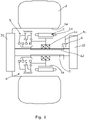
- FIG 1 schematically shows a drive system in the form of an electric hub drive.
- the hub drive comprises an electric motor 1 for driving a wheel 2 and as can be seen schematically in Figure 1 , the majority of the hub drive may be housed in the hub 2a of the wheel 2.
- the motor 1 comprises a stator 1a and a rotor 1b which is mounted for rotation via bearings 1c about an output shaft 3.
- the output shaft 3 is arranged for rotatingly driving the wheel 2 via a gear reduction stage 31.
- a braking system 32 is provided for breaking rotation of the output shaft 3 and hence rotation of the wheel 2.
- the structure and operation of the gear reduction stage 31 and braking system 32 are not particularly pertinent to the present invention and detailed description thereof is omitted. Indeed in some implementations the gear reduction stage and braking system might be omitted.
- the hub drive system further comprises gearing apparatus 4 which in turn comprises a gearing assembly 5 and a shift arrangement 6 for acting on the gearing assembly 5 and changing between gears.
- the gearing assembly 5 includes the shaft 3 as a rotary output member.
- the gearing assembly 5 comprises a dog hub 51 which is mounted for axial movement relative to the output shaft 3 but with rotational movement between the dog hub 51 and shaft 3 resisted.
- this mounting is achieved via the provision of mutually engaging splines on the outer curved surface of the shaft 3 and in the bore of the dog hub 51.
- the gearing assembly 5 also comprises a gearing arrangement 52 which comprises a plurality of planetary gear stages.
- Each planetary gear stage comprises a sun gear 521a, 521b, 521c and planetary gears 522 carried on a respective planet carrier 523.
- a common fixed ring gear 524 is provided within which the planetary gears 522 can run.
- Each planet carrier 523 is bourne on the sun gear 521b, 521c of the subsequent planetary gear stage.
- a first of the sun gears 521a in the series is carried by the motor rotor 1b so as to rotate therewith.
- Each of the planetary gear stages act as a reduction gear. These gear stages preferably use planet gears which are small in comparison with the sun gear to give a relatively low reduction ratio of say in the order of 2.7:1 per stage.
- gear stages of approximately 2.7:1 which therefore gives a mechanical ratio spread of approximately 7:1 and combined with a traction motor, this can give a range of approximately 20:1.
- This ratio spread is typical of that required for a high performance military vehicle, either a wheel driven vehicle with a hub drive or a tracked vehicle.
- a third planetary gear stage could be added to give an overall spread of approximately 50:1.
- Each sun gear 521a, 521b, 521c comprises a dog ring 53 which is arranged for cooperation with the dog hub 51 so as to act as a dog clutch.
- Each dog ring 53 correspondingly acts as an output of the gearing arrangement 52.
- Figures 3A and 3B show the dog hub 51 and one of the dog rings 53 in isolation. In Figure 3A these parts are shown separately from one another whereas in Figure 3B they are shown engaged with one another. Incidentally, in Figure 3B , the dog ring 53 is shown carrying planetary gears 522 whereas in Figure 3A there are no planetary gears. Thus this corresponds to the dog ring 53 carried by the first sun gear 521a which does not act as a planet carrier.
- the dog hub 51 carries a hub set of dog teeth 51a and the dog ring 53 carries a ring set of dog teeth 53a. These sets of teeth are radially extending and arranged to mutually engage with one another as shown in Figure 3B . That is to say the dog hub 51 is arranged to engage with the dog ring 53 when appropriately axially aligned with one another. Thus the dog hub 51 may be moved axially between positions where it engages with the dog ring 53 of the first sun gear 521a or the dog ring 53 of the second sun gear 521b or the dog ring 53 of the third sun gear 521c.
- the dog hub 51 may also be moved to intermediate positions where there is no engagement such that "neutral" positions can be adopted between gears. Furthermore the dog hub 51 may be moved between all of these positions by use of the shift arrangement 6 as will be described in more detail further below.
- the teeth in the hub set of teeth 51a are provided on a curved circumferential surface of the dog hub 51.
- Teeth in the ring set of teeth 53a are provided on a curved (inner) circumferential surface of the dog ring 53.
- Each tooth has a root at the respective curved surface and projects radially therefrom.
- the hub set of teeth 51a and ring sets of teeth 53a are arranged to allow rotational drive to be transferred from the respective sun gear 521a, 521b, 521c to the output shaft 3 via the dog hub 51 when there is appropriate alignment. Further the teeth 51a, 53a are arranged to allow engagement to be achieved by movement of the hub 51 axially into alignment with the respective dog ring 53 and to allow disengagement by axial movement away from that aligned position when not under rotational load.
- the sets of teeth 51a, 53a are arranged so that the set of hub teeth 51a may pass through the set of ring teeth 53a when there is appropriate register between the sets of teeth.
- the sets of teeth 51a, 53a are in register and thus disengagement of the teeth by movement of the hub 51 in either axial direction away from the engaging position is possible.
- the dog hub 51 may be moved from a first position in which it is engaged with the dog ring 53 of the second sun gear 521b to a first disengaged position which is axially to one side of its engaged position and to a second disengaged position which is axially to the other side of its first engaged position. Furthermore from the disengaged positons the dog hub 51 may be moved to second and third engaged positions, that is respectively into engagement with the dog ring 53 of the first sun gear 521a or the dog ring 53 of third sun gear 521c.
- a further planetary gear stage is provided then this may be engaged using the same mechanism. That is to say a fourth dog clutch arrangement may be provided with an appropriate dog ring carried on a fourth sun gear.
- the hub set of teeth 51a and the ring set of teeth 53a are profiled to help with operation of the system. First facing edges of the teeth which will contact with the respective other set of teeth during engagement are radiused to reduce contact stress and help to guide the teeth into engagement with one another. These radiused portions can be seen for example in Figures 4A and 4B .
- radiused surfaces 51b are provided at outer edges of the teeth and side walls of the teeth.
- radiused surfaces 53b are provided at the tips of the teeth, in troughs between the teeth and on sidewalls of the teeth.
- the respective sets of teeth 51a, 53a are profiled to encourage engagement and alignment of the teeth to be maintained when under rotational load when the respective dog clutch is transferring load.
- the mating surfaces of the teeth which transfer such load comprise complementary concave and convex portions which can rest in one another during rotational drive.
- the dog hub teeth 51a have a groove 51c provided in a side wall surface which is arranged to accept a corresponding convex portion 53c in the dog ring teeth 53a to help maintain alignment between the respective sets of teeth under rotational load.
- the convex portions 53c will tend to nestle into the concave groove portions 53c so resisting axial movement of the dog hub 51 out of engagement with the dog ring 53.
- the shift arrangement 6 comprises a shift fork 61 for accepting inputs from a user and at least one shift stick 62 for transmitting inputs from the shift fork 61 to the dog hub 51.
- the arrangement allows axial movement of the shift fork 61 to cause a corresponding axial movement of the dog hub 51.
- the shift fork 61 is provided on the opposite side of the motor 1.
- This again allows more flexibility in the arrangement of the system and for example allows the provision of the shift fork 61 to be on an inboard side of the motor whereas the gearing arrangement is on the outboard side of the motor.
- This can help from an overall system design point of view.
- this can help to lead to a more compact arrangement where, as can be seen for example by consideration of Figure 2 , part of the axial extent of the dog hub 51 may be accommodated at least partly within the axial extent of the motor rotor 1b. In the present case this is true at least when the dog hub 51 is in position which corresponds to it being retracted to its maximum extent towards the location of the motor 1.
- the shift arrangement 6 comprises a shift ring 63 to which are connected three shift sticks 62 with the remote end of the shift sticks 62 being connected to the dog hub 51.
- Each of the shift sticks 62 is located in a respective axial slot 33 provided in the outer curved surface of the shaft 3.
- These slots 33 and hence the shift sticks 62 may be equally spaced around the circumference of the shaft 3.
- the shift sticks 62 are spaced in this way and thus are spaced 120° from each other.
- the slots for the shift sticks may be machined into the outer curved surface of the shaft 3.
- the shift sticks 62 pass through the interior of the bearing 1c and hence through the rotor 1b.
- the shift ring 63 is arranged to be acted on via the shift fork 61 so the axial movement of the shift fork 61 will cause axial movement of the dog hub 51 via the shift ring 63 and the shift sticks 62.
- each dog hub may have its own respective associated set of shift sticks 62 and respective shift ring 63 for control by a respective shift fork.
- Figure 6 shows an alternative gearing apparatus which is similar to that shown in Figure 2 . Detailed description of most of Figure 6 is omitted for the sake of brevity with it being understood that those features not described are the same as those of the gearing apparatus shown in Figure 2 .
- the difference between the gearing arrangement shown in Figure 6 and that shown in Figure 2 is that an additional reduction gear stage 54 is provided between the motor rotor 1b and the remainder of the gearing arrangement 52.
- the output of this first reduction gear 54 acts as the input to the first sun gear 521a such that the highest gear available is via this reduction gear 54 and all the other gears are reduced.
- the reduction gear arrangement 31 of Figure 1 between the output shaft 3 and the wheel 2 to be driven might be omitted.
- FIG. 7 schematically shows yet another gearing apparatus. Again this is similar to that described above in relation to Figures 2 and a detailed description of those parts in common is omitted with it to be understood that those parts not described are the same as in the apparatus of Figure 2 .
- gearing assembly 5 is provided where different forms of dog clutch are provided but otherwise the gearing assembly is as described in relation to Figures 2 to 5 .
- the dog hub 51 carries separate sets of dog teeth 51a, 51a' and 51a". Further the sun gears of the gearing arrangement 52 carry different types of dog ring 53, 53' and 53".
- the first set of dog teeth 51a is arranged for engagement with the dog ring 53 carried by the second sun gear 521b.
- This set of dog teeth 51a and dog ring 53 are of the type described above and shown, for example in Figures 3A and 3B . That is to say the respective dog teeth 51a, 53a are radially extending and arranged so that when aligned and engaged, rotational drive may be transmitted via the sets of dog teeth 51a, 53a and also so that the teeth may be moved out of axial alignment with each other in either direction away from the aligned position.
- the second and third sets of dog teeth 51a', 51a" provided on the dog hub 51 are of the more conventional axial extending type and are arranged for mutual engagement with corresponding axial sets of teeth 53', 53" provided on the first sun gear 521a and the third sun gear 521c.
- these sets of teeth extend from axial faces on the dog hub 51, and sun gears 521a, 521c.
- Figure 8 shows the type of dog teeth arrangements which may be used for these dog clutches.
- first dog clutch 53, 51a is one of the type where the two sets of dog teeth may pass through one another
- second 53', 51a' and third 53", 51a" dog clutches are ones where engagement is provided by axial movement in a first direction and disengagement can only be achieved by axial movement in the reverse direction.
- engagement of the second set of hub teeth 51a' with the corresponding dog ring 53' may be achieved with the dog hub 51 at one axial extent of its movement whilst engagement of the third set of hub teeth 51a" may be achieved with the corresponding dog ring 53" with the hub 51 at its opposite axial extent of travel.
- engagement of the first dog clutch via the first set of dog teeth 51a and the appropriate dog ring 53 may be provided at an intermediate axial position of the dog hub 51.
- the arrangement shown in Figure 7 might be advantageous in some circumstances in that whilst the first dog clutch 53, 51a provides the capability of having more than two gears with the provision of a single axially moveable dog hub, the use of the more conventional dog clutches 53', 51a'; 53", 51a" at either end of the dog hub 51 can facilitate the provision of different torque transfer capabilities of the dog clutches and/or the provision of different diameters of dog clutch which may be useful, bearing in mind available space requirements.
- a larger diameter dog clutch may be used where greater torque transfer capabilities are required and/or where greater internal space within the dog clutch might be useful.
- a smaller diameter dog clutch might be used where lower torque transfer capabilities are required and/or where space outside of the dog clutch might be useful/required for some other purpose.
Description
- This invention relates to gearing assemblies and apparatus.
- Gearing assemblies and apparatus of the present kind may be found useful in a variety of vehicular applications or in other machinery where a simple robust and compact gearbox is useful. Gearing assemblies are used commonly on vehicles where it is desired to drive a wheel or axle at a different rotational speed to the revolutions of an engine or motor. Assemblies of the present kind may find a particular application in a gearing system for an electrical hub drive and applications of the present systems are discussed herein in that context by way of example, although it should be noted that the invention is not limited to such applications.
- Electric hub drive or hub mounted electric drive (HMED) units are finding increasing use in vehicles where it is advantageous for the wheels to be driven independently. Applications include, for example large vehicles and vehicles adapted for use on difficult, for example steep and uneven, terrain. HMED units are finding increasing use on hybrid vehicles. HMED units are finding increasing use on military vehicles particularly for use on difficult terrain.
- In such a system each wheel is provided with a hub mounted electric drive assembly, typically comprising a housing containing an electric motor and a drive train including a drive shaft arranged inside a suitable hub mounted housing. An output shaft of the hub drive drives the wheel. The hub drive assembly can fit at least partly within space available inside the diameter and the overall width of the wheel rim and tyre assembly, in at least some cases.
- The use of individual hub mounted electric drive units can eliminate the need for conventional transmission and drive shafts and can offer enhanced vehicle capabilities through improvements in vehicle performance, fuel economy, design configuration, increased stealth capability and reduced whole of life costs. Generally an electric hub drive will be such that it needs to have a large torque range and a large speed range as well as desirably being compact. A multispeed gear change mechanism is desirable to facilitate this. Higher gear ratios can be used to provide higher torques at lower speeds and lower gear ratios can be used to allow for higher speeds (with low available output torque).
- In providing gearing assemblies and apparatus for, amongst other things, use in such units, it is desirable if a compact design can be achieved and if there is flexibility in terms of the positioning of various parts of the gearing assembly and/or apparatus necessary to provide the different gear changes and where appropriate, flexibility for positioning controls operable by a user for controlling those gear changes.
- In some previous designs of gearing assemblies or apparatus, two separate shift forks have been provided for making gear changes. One for operating a corresponding clutch on a first side of a driving motor of the system, and one for operating two separate clutches provided on a second side of the motor.
- One example of such a gearing assembly is shown in
WO2016/146628 . In that device, three different gears are provided. Two of the gears are selectable by use of a first shift fork provided on one side of the motor using first and second dog clutches. In that arrangement, the dog clutches operate using mutually engageable axially extending teeth such that in order to engage the clutch, a dog hub carrying axially extending teeth is moved axially into engagement with corresponding teeth on the remainder of the clutch and in order to disengage the clutch, the dog hub is moved in the axially opposite direction. As such, axial movement of the dog hub to its maximum extent in one direction engages a first dog clutch whereas axial movement of the dog hub in the opposite axial direction to the maximum extent engages a second dog clutch. With the arrangement ofWO2016/146628 , in order to provide the third gear, a third dog clutch and a second shift fork for operating the third clutch are provided on the other side of the motor. -
US 3,386,302 describes a manually-controlled, multiple-ratio geared transmission for use in an automotive vehicle driveline. The transmission includes a clutch sleeve engageable selectively with each of several power output gears. The transmission includes a synchroniser clutch shaft which extends through the torque output gears. The clutch shaft carries positive engagement teeth that are adapted to mesh with clutch teeth carried by each of the individual torque output gears. During use, the clutch shaft is shifted in the direction of a common axis of the torque output gears, allowing the clutch teeth of the clutch shaft to selectively engage the clutch teeth of the various torque output gears thereby establishing a connection between the torque input shaft and the clutch shaft via the respective torque output gears. - It would be desirable to provide gearing assemblies and apparatus which provide more flexibility in design and, for example can allow the provision of a more compact design and/or allow a choice of position for a shift fork associated with a respective clutch.
- According to a first aspect of the present invention there is provided a gearing assembly comprising a rotary input member, a rotary output member and a gearing arrangement between the input member and the output member selectively engageable to effect a driving engagement between the input member and the output member through at least a first torque connection having a first gear ratio and a second torque connection having a second gear ratio,
- wherein one of the rotary input member and the rotary output member comprises a first shaft, the first torque connection comprises a first dog clutch comprising a dog hub comprising a hub set of teeth and a surrounding dog ring comprising a ring set of teeth, the hub and ring sets of teeth being radially projecting and mutually engageable, and the second torque connection comprises a second dog clutch,
- the dog hub being mounted on the first shaft so as to allow axial movement of the dog hub relative to the shaft and dog ring with rotation of the dog hub relative to the shaft being resisted such that when the dog hub is axially aligned with the dog ring, the hub and ring sets of teeth engage and rotational drive may be transferred between the first shaft and the dog ring,
- further wherein the hub and ring sets of teeth are dimensioned and spaced so that upon axial movement between the dog hub and the dog ring with the sets of teeth appropriately in register with one another, the teeth in each set may pass through spacings between the teeth in the respective other set, so that the dog hub is moveable between a first disengaged position with the hub set of teeth axially spaced in a first direction from the ring set of teeth, a first engaged position with the hub set of teeth aligned and engaged with the ring set of teeth, and a second disengaged position with the hub set of teeth axially spaced in a second direction from the ring set of teeth, wherein
- the gearing arrangement comprises a first planetary gear stage having fixed ring gear and a sun gear which comprises the dog ring of the first dog clutch.
- This arrangement allows the dog hub to pass through the dog ring so allowing a greater flexibility in the way that the gearing assembly can be arranged. This is because the dog hub may be moved axially in both directions away from the engaged position. This contrasts with the conventional dog clutches used in pre-existing systems which do not allow the dog hub to pass through an engaged position such as to allow only axial movement in one way away from the engaged position. Thus for example, as well as the dog hub being moveable into and out of engagement with the dog ring of the dog clutch of the first torque connection it may be moved to a position allowing use of a second torque connection, or a third torque connection, or even a higher number of independent connections. Further those connections might be via the same set of dog teeth on the dog hub or via a different set of teeth on the same dog hub, or via a different dog hub, or using a different type of clutch, or so on.
- The second dog clutch may comprise a respective dog hub comprising a respective hub set of teeth and a respective surrounding dog ring comprising a respective ring set of teeth, the respective hub and ring sets of teeth being radially projecting and mutually engageable, the gearing arrangement comprising a second planetary gear stage having a fixed ring gear and a sun gear which comprises the dog ring of the second dog clutch and wherein the dog ring of the second dog clutch comprises a planetary gear carrier of the first planetary gear stage.
- In some embodiments the dog hub of the second dog clutch may be the same dog hub as the dog hub of the first dog clutch - to put this another way the first and second dog clutches may share a common dog hub. In such a case the dog hub will be moveable between the first engaged position in which driving engagement between the input member and the output member is effected through the first torque connection and a second engaged position in which driving engagement between the input member and the output member is effected through the second torque connection; wherein the first and second planetary gear stages share a common fixed ring gear.
- In some cases the dog hub may have a common hub set of teeth for selective engagement with the ring set of teeth of the first dog clutch and the ring set of teeth of a second dog clutch. In other cases the dog hub may comprise a first hub set of teeth for selective engagement with the ring set of teeth of the first dog clutch and a second hub set of teeth for selective engagement with the ring set of teeth of a second dog clutch.
- In other embodiments the gearing assembly may comprise a plurality of dog hubs. The first torque connection may comprise a first dog hub. The second torque connection may comprise a second dog hub which is independent of the first dog hub.
- The gearing assembly may comprise a plurality of clutches, say dog clutches, each associated with a respective torque connection.
- In some cases the gearing assembly may comprise at least three torque connections each comprising an associated dog clutch comprising a dog hub comprising an associated hub set of teeth and an associated surrounding dog ring comprising an associated ring set of teeth, the associated hub and ring sets of teeth being radially projecting and mutually engageable, and each of these may have the same overall construction as the first dog clutch. In other words the gearing arrangement may comprise a planetary gear stage associated with each of the at least three torque connections, each associated planetary gear stage having a sun gear which comprises the dog ring of the associated dog clutch and wherein the sun gear of each associated planetary gear stage is arranged to bear a planetary gear carrier of a preceding planetary gear stage within the gearing arrangement.
- In other cases at least one second or subsequent clutch may have a different construction from the first dog clutch. The at least one second or subsequent clutch may comprise a dog hub with axially extending teeth. Thus, the first hub set of teeth may extend radially from the dog hub and may be drivingly engageable with radially extending teeth on the ring set of the first dog clutch, and the second hub set of teeth may extend axially from the dog hub and may be drivingly engageable with axially extending teeth on the ring set of the second dog clutch.
- In one set of embodiments the gearing assembly may comprise a gearing arrangement between the input member and the output member selectively engageable to effect a driving engagement between the input member and the output member through at least a first torque connection having a first gear ratio, a second torque connection having a second gear ratio, and a third torque connection having a third gear ratio, wherein the first torque connection comprises a first dog clutch, the second torque connection comprises a second dog clutch, and the third torque connection comprises a third dog clutch.
- In a subset of those embodiments the first, second, and third dog clutches comprise a common dog hub which is arranged for movement axially between the first engaged position in which driving engagement between the input member and the output member is effected through the first torque connection, a second engaged position in which driving engagement between the input member and the output member is effected through the second torque connection, and a third engaged position in which driving engagement between the input member and the output member is effected through the third torque connection, wherein the first engaged position is axially between the second engaged position and the third engaged position.
- In such a case the common dog hub may comprise a common set of hub teeth which is for selective engagement with the dog ring of the first dog clutch and respective dog rings of the second dog clutch and the third dog clutch. In such a case each dog clutch may be of the same overall design as the first dog clutch and for example the common hub set of teeth may be arranged so as to be able to pass through respective ring sets of teeth on each dog ring. In this way of course there may be one or more further dog clutch in addition to the three mentioned above, engagement of which may be reached by a further axial movement of the common dog hub.
- Alternatively the second and/or third dog clutch may be of a different kind than the first dog clutch. Further the common dog hub may comprise two or more hub sets of teeth each for engaging with a corresponding remaining portion of at least one of the first, second, and third dog clutch. The second and/or third dog clutch may be arranged so as to not allow the dog hub to pass through a respective engaged position such as to allow only axial movement in one way away from the engaged position.
- The second and/or third dog clutch may comprise axially extending dog teeth for achieving driving engagement between the dog hub and the remainder of the respective dog clutch. The dog teeth may comprise teeth provided on an axially facing face of the dog hub.
- Where there is a plurality of dog clutches at least one of the dog clutches may be arranged to withstand a differing level of torque from at least another of the dog clutches.
- At least one of the dog clutches may have a different diameter than at least one other of the dog clutches. This can help give higher torque transfer capability for gear ratios giving lower output speed, whilst minimising the space occupied by a dog clutch which is to carry drive at higher output speeds.
- The first shaft and the dog hub may be provided with mutually engaging splines for mounting the dog hub on the shaft so as to allow relative axial movement whilst resisting relative rotational movement.
- The or each dog ring may act as an output (or an input) of the gearing arrangement.
- The gearing arrangement may comprise a plurality of planetary gear stages. Each planetary gear stage may comprise a sun gear, which sun gear comprises said remainder of a respective dog clutch arranged for engagement with the respective hub set of dog teeth. Each sun gear may comprise a respective dog ring of one of the plurality of dog clutches.
- Each planetary gear stage may comprise a planetary gear carrier.
- The hub set of teeth and the ring set of teeth may be profiled to encourage ease of engagement whilst discouraging dis-engagement when under rotational driving load. The hub set of teeth and the ring set of teeth may be profiled to encourage ease of dis-engagement when not under rotational driving load.
- The teeth of the hub set of teeth and/or the ring set of teeth may comprise radiused contact surfaces to encourage engagement.
- The engaging surfaces of teeth of the hub set of teeth and the ring set of teeth may comprise complementary convex and concave surface portions such that when the sets of teeth are aligned, the convex portions on one set of teeth tend to rest in the concave portions of the other set of teeth so as to resist relative axial movement between the sets of teeth when under rotational load.
- One set of teeth may comprise grooves into which a corresponding convex portions of the other set of teeth can project when the two sets of teeth are aligned and under rotational load. Preferably, where present, the grooves are provided in the hub set of teeth. Generally this will ease machining.
- According to a second aspect of the invention there is provided gearing apparatus comprising a gearing assembly as defined above, a motor comprising a stator and a rotor journaled for rotation relative to the first shaft via a bearing provided around the first shaft such that the first shaft passes through said bearing, and a shift arrangement for shifting the gearing arrangement between a first state in which there is driving engagement between the input member and the output member through the first torque connection and a second state in which the gearing arrangement does not provide driving engagement between the input member and the output member through the first torque connection, wherein the gearing arrangement is provided at a location spaced axially in a first direction from the motor rotor and a shift fork for operating the shift arrangement is provided at a location spaced axially in a second, opposite, direction from the motor rotor.
- Preferably the shift arrangement comprises at least one shift stick for acting on the gearing assembly for shifting the gearing arrangement between at least the first state and the second state and the at least one shift stick is carried in a slot in the outer surface of the first shaft and arranged for axial movement relative to the shaft for acting on the gearing assembly in shifting the gearing arrangement between the first state and the second state.
- According to an example of the present invention there is provided a gearing apparatus comprising a gearing assembly comprising a rotary input member, a rotary output member and a gearing arrangement between the input member and the output member selectively engageable to effect a driving engagement between the input member and the output member through at least a first torque connection having a first gear ratio and a second torque connection having a second gear ratio,
- the gearing apparatus further comprising a shift arrangement for shifting the gearing arrangement between a first state in which there is driving engagement between the input member and the output member through the first torque connection and a second state in which the gearing arrangement does not provide driving engagement between the input member and the output member through the first torque connection,
- the shift arrangement comprising at least one shift stick for acting on the gearing assembly for shifting the gearing arrangement between at least the first state and the second state,
- wherein one of the rotary input member and the rotary output member comprises a first shaft and the at least one shift stick is carried in a slot in the outer surface of the first shaft and arranged for axial movement relative to the shaft for acting on the gearing assembly in shifting the gearing arrangement between the first state and the second state.
- Preferably the gearing arrangement has a third state in which there is driving engagement between the input member and the output member through the second torque connection and the at least one shift stick is arranged for acting on the gearing assembly for shifting the gearing arrangement between at least the first state, the second state and the third state.
- The shift arrangement may comprise a shift fork operable by a user for moving the at least one shift stick axially relative to the shaft so as to shift the gearing arrangement.
- The shifting arrangement may comprise a plurality of shift sticks which are angularly spaced from one another around the first shaft.
- The plurality of shift sticks may be arranged to act in parallel with one another on the gearing assembly. The plurality of shift sticks may be arranged to act independently of one another on the gearing assembly.
- The plurality of shift sticks may be arranged in respective sets, with the or each shift stick in a respective set arranged to act in parallel with any other members of the set, whilst acting independently of the or each shift stick in any other set or sets.
- The shift arrangement may comprise at least one pair of shift sticks which are arranged to act in parallel on the gearing assembly.
- The pair of shift sticks may be disposed in respective slots which are diametrically opposed around the shaft.
- Most likely if shift sticks are arranged in a pair there will be two pairs, each pair acting as a pair in parallel and independently of the other pair.
- The shift arrangement may comprise three (or more) shift sticks which are arranged to act in parallel on the gearing assembly.
- The three (or more) shift sticks may be disposed in respective slots which are equally spaced around the shaft.
- The shift arrangement may comprise a shift ring which is arranged to transfer actuation from the shift fork to at least one shift stick. Where there are sets of shift sticks a separate respective shift ring may be provided for each set to facilitate independent control of each set.
- The gearing assembly may comprise at least one clutch for use in shifting the gearing arrangement between states, the clutch comprising at least one clutch hub which is mounted on the first shaft so as to allow axial movement of the clutch hub relative to the shaft with rotation of the clutch hub relative to the shaft being resisted, wherein the at least one shift stick is arranged for acting on the at least one clutch hub for causing axial movement thereof.
- The first torque connection may comprise a clutch hub mounted on the first shaft so as to allow axial movement of the clutch hub relative to the shaft whilst rotation of the clutch hub relative to the shaft is resisted and the shift arrangement may be arranged for causing axial movement of the clutch hub relative to the shaft under action of the at least one shift stick to shift the gearing arrangement at least between the first and the second state.
- Where there are sets of shift sticks each set may be arranged for acting on a respective clutch hub. In this way each set of sticks may be used for axial movement of a respective clutch hub independently of the other clutch hubs. Thus one set of sticks say may be used for controlling engagement of a first gear/torque connection by, for example, axial movement of a first clutch hub and another set of sticks say may be used for controlling engagement of a second gear/torque connection by, for example, axial movement of a second clutch hub.
- The at least one clutch may be a dog clutch and the clutch hub may be a dog hub.
- Generally the rotary output member will comprise the first shaft.
- According to a third aspect of the present invention there is provided a drive system comprising a gearing assembly or gearing apparatus as defined above in relation to the foregoing aspects of the invention, wherein the drive system is comprised within a vehicle.
- The rotor of the motor may be journaled for rotation relative to the first shaft via a bearing provided around the first shaft, such that the first shaft passes through said bearing.
- The rotor of the motor may be coupled to the rotary input member of the gearing assembly for providing rotary drive thereof.
- The rotary output member may be coupled to a wheel or other body to which it is desired to provide rotational drive.
- The gearing assembly may comprise a reduction gear, which may be separate from the gearing arrangement. Where it is separate from the gearing arrangement, the reduction gear may, for example, be provided in the drive train between the rotor of the motor and the rotary input member or between the rotary output member and the wheel or other body.
- The gearing arrangement may be provided at a location spaced axially in a first direction from the motor rotor. A shift fork for operating the shift mechanism may be provided at a location spaced axially in a second, opposite, direction from the motor rotor.
- Thus the at least one shift stick may pass from one side of the motor rotor to the other, by virtue of running in the axially extending slot provided in the first shaft. Thus the shift stick may pass through the bearing supporting the motor rotor.
- This arrangement can help allow provision of a shift fork on a desired side of the motor irrespective of the which is the desired side for the gearing arrangement. Thus for example parts of the gearing arrangement might be conveniently be housed in space in a wheel hub whilst the shift fork is on the inboard side of the motor.
- Similarly it can be convenient if part of the axial extent of the dog hub can be accommodated within the axial extent of the motor rotor when the hub is at an axially inward end (with respect to motor rotor location) of its travel.
- Note that in general each of the optional features following each of the aspects of the invention above is equally applicable as an optional feature in respect of each of the other aspects of the invention and could be re-written after each aspect with any necessary changes in wording. Not all such optional features are re-written after each aspect merely in the interests of brevity.
- Embodiments of the present invention will now be described, by way of example only, with reference to the accompanying drawings in which:
-
Figure 1 shows a drive system in the form of a hub drive system and including gearing apparatus; -
Figure 2 schematically shows in more detail part of the gearing apparatus of the drive system shown inFigure 1 ; -
Figure 3A and Figure 3B show a dog hub and dog ring of the gearing apparatus shown inFigure 2 , with the dog hub and dog ring shown separately inFigure 3A and shown in an engaged position inFigure 3B ; -
Figure 4A and Figure 4B show respectively in more detail the teeth provided on the dog hub (Figure 4A ) and the dog ring (Figure 4B ) ofFigures 3A and 3B ; -
Figure 5A shows in more detail part of a shift arrangement of the gearing apparatus ofFigure 2 in position on a shaft of the gearing apparatus; -
Figure 5B shows part of the shift arrangement in isolation when not mounted on the shaft; -
Figure 5C shows the shaft in isolation without the shift arrangement in position; -
Figure 6 schematically shows an alternative gearing apparatus which is similar to that shown inFigure 2 ; -
Figure 7 shows yet another gearing apparatus which has some similarities with that shown inFigures 2 but has a different arrangement of dog clutches; and -
Figure 8 shows the engaging components of dog clutches of the type which may be used in some of the dog clutches of the gearing apparatus shown inFigure 7 . -
Figure 1 schematically shows a drive system in the form of an electric hub drive. The hub drive comprises anelectric motor 1 for driving a wheel 2 and as can be seen schematically inFigure 1 , the majority of the hub drive may be housed in thehub 2a of the wheel 2. Themotor 1 comprises astator 1a and arotor 1b which is mounted for rotation viabearings 1c about anoutput shaft 3. Theoutput shaft 3 is arranged for rotatingly driving the wheel 2 via agear reduction stage 31. Further abraking system 32 is provided for breaking rotation of theoutput shaft 3 and hence rotation of the wheel 2. The structure and operation of thegear reduction stage 31 andbraking system 32 are not particularly pertinent to the present invention and detailed description thereof is omitted. Indeed in some implementations the gear reduction stage and braking system might be omitted. - The hub drive system further comprises gearing
apparatus 4 which in turn comprises agearing assembly 5 and ashift arrangement 6 for acting on thegearing assembly 5 and changing between gears. The gearingassembly 5 includes theshaft 3 as a rotary output member. - Considering now
Figure 2 as well asFigure 1 , the gearingassembly 5 comprises adog hub 51 which is mounted for axial movement relative to theoutput shaft 3 but with rotational movement between thedog hub 51 andshaft 3 resisted. In the present embodiment, this mounting is achieved via the provision of mutually engaging splines on the outer curved surface of theshaft 3 and in the bore of thedog hub 51. - The gearing
assembly 5 also comprises agearing arrangement 52 which comprises a plurality of planetary gear stages. Each planetary gear stage comprises asun gear planetary gears 522 carried on arespective planet carrier 523. A common fixedring gear 524 is provided within which theplanetary gears 522 can run. Eachplanet carrier 523 is bourne on thesun gear - A first of the
sun gears 521a in the series is carried by themotor rotor 1b so as to rotate therewith. Each of the planetary gear stages act as a reduction gear. These gear stages preferably use planet gears which are small in comparison with the sun gear to give a relatively low reduction ratio of say in the order of 2.7:1 per stage. - In the present embodiment there are two gear stages of approximately 2.7:1 which therefore gives a mechanical ratio spread of approximately 7:1 and combined with a traction motor, this can give a range of approximately 20:1. This ratio spread is typical of that required for a high performance military vehicle, either a wheel driven vehicle with a hub drive or a tracked vehicle. For a vehicle with a lower power to weight ratio, a third planetary gear stage could be added to give an overall spread of approximately 50:1.
- Where a planetary gear reduction is used with a ratio of approximately 2.7:1 and this has small planet gears, this will lead to relatively large sun gears. This is advantageous as it provides space inside the sun gears which can be used.
- Each
sun gear dog ring 53 which is arranged for cooperation with thedog hub 51 so as to act as a dog clutch. Eachdog ring 53 correspondingly acts as an output of thegearing arrangement 52. -
Figures 3A and 3B show thedog hub 51 and one of the dog rings 53 in isolation. InFigure 3A these parts are shown separately from one another whereas inFigure 3B they are shown engaged with one another. Incidentally, inFigure 3B , thedog ring 53 is shown carryingplanetary gears 522 whereas inFigure 3A there are no planetary gears. Thus this corresponds to thedog ring 53 carried by thefirst sun gear 521a which does not act as a planet carrier. - As can be seen most clearly in
Figures 3A and 3B , thedog hub 51 carries a hub set ofdog teeth 51a and thedog ring 53 carries a ring set ofdog teeth 53a. These sets of teeth are radially extending and arranged to mutually engage with one another as shown inFigure 3B . That is to say thedog hub 51 is arranged to engage with thedog ring 53 when appropriately axially aligned with one another. Thus thedog hub 51 may be moved axially between positions where it engages with thedog ring 53 of thefirst sun gear 521a or thedog ring 53 of thesecond sun gear 521b or thedog ring 53 of thethird sun gear 521c. It will be appreciated that thedog hub 51 may also be moved to intermediate positions where there is no engagement such that "neutral" positions can be adopted between gears. Furthermore thedog hub 51 may be moved between all of these positions by use of theshift arrangement 6 as will be described in more detail further below. - The teeth in the hub set of
teeth 51a are provided on a curved circumferential surface of thedog hub 51. Teeth in the ring set ofteeth 53a are provided on a curved (inner) circumferential surface of thedog ring 53. Each tooth has a root at the respective curved surface and projects radially therefrom. - The hub set of
teeth 51a and ring sets ofteeth 53a (a portion of which are shown in more detail inFigures 4A and 4B ) are arranged to allow rotational drive to be transferred from therespective sun gear output shaft 3 via thedog hub 51 when there is appropriate alignment. Further theteeth hub 51 axially into alignment with therespective dog ring 53 and to allow disengagement by axial movement away from that aligned position when not under rotational load. - Furthermore the sets of
teeth hub teeth 51a may pass through the set ofring teeth 53a when there is appropriate register between the sets of teeth. As will be appreciated, when engagement has been achieved as shown inFigure 3B , the sets ofteeth hub 51 in either axial direction away from the engaging position is possible. - Thus the
dog hub 51 may be moved from a first position in which it is engaged with thedog ring 53 of thesecond sun gear 521b to a first disengaged position which is axially to one side of its engaged position and to a second disengaged position which is axially to the other side of its first engaged position. Furthermore from the disengaged positons thedog hub 51 may be moved to second and third engaged positions, that is respectively into engagement with thedog ring 53 of thefirst sun gear 521a or thedog ring 53 ofthird sun gear 521c. - With the
dog hub 51 axially positioned so that itsteeth 51a are engaged with thedog ring 53 of thefirst sun gear 521a, drive is provided directly from themotor rotor 1b to theoutput shaft 3 via thedog ring 53 of thefirst sun gear 521a and thedog hub 51. Here thedog ring 53 of thefirst sun gear 521a and thedog hub 51 are acting as a first dog clutch. - When the
dog hub 51 is axially aligned with thedog ring 53 of thesecond sun gear 521b, then rotational drive from themotor rotor 1b occurs via the first planetary gear stage with thedog ring 53 of thesecond sun gear 521b and thedog hub 51 acting as a second dog clutch. Here there is a speed reduction so theoutput shaft 3 rotates more slowly than themotor rotor 1b. - Similarly when the
dog hub 51 is aligned with thedog ring 53 of thethird sun gear 521c then drive from themotor rotor 1b is provided to theshaft 3 via two planetary gear stages with thedog ring 53 of thethird sun gear 521c anddog hub 51 acting as a third dog clutch. - It will be appreciated that if a further planetary gear stage is provided then this may be engaged using the same mechanism. That is to say a fourth dog clutch arrangement may be provided with an appropriate dog ring carried on a fourth sun gear.
- Thus one "common"
dog hub 51 and appropriate shift arrangement can be used to provide any number of gears desired. The hub set ofteeth 51a and the ring set ofteeth 53a are profiled to help with operation of the system. First facing edges of the teeth which will contact with the respective other set of teeth during engagement are radiused to reduce contact stress and help to guide the teeth into engagement with one another. These radiused portions can be seen for example inFigures 4A and 4B . On the hub set ofteeth 51a,radiused surfaces 51b are provided at outer edges of the teeth and side walls of the teeth. On the ring set ofteeth 53a radiusedsurfaces 53b are provided at the tips of the teeth, in troughs between the teeth and on sidewalls of the teeth. - It will be noted that during engagement of the sets of
teeth dog hub 51 and thedog ring 53. Theseradiused surfaces - Furthermore the respective sets of
teeth dog hub teeth 51a have agroove 51c provided in a side wall surface which is arranged to accept a correspondingconvex portion 53c in thedog ring teeth 53a to help maintain alignment between the respective sets of teeth under rotational load. As will be appreciated, under rotational load, theconvex portions 53c will tend to nestle into theconcave groove portions 53c so resisting axial movement of thedog hub 51 out of engagement with thedog ring 53. - It will be appreciated that with the above described gearing assembly a shift fork might be provided for directly acting on the
dog hub 51 for shifting its axial position to select the desired gears. - However in the present arrangement a different form of shifting
arrangement 6 is provided. As schematically illustrated inFigure 1 theshift arrangement 6 comprises ashift fork 61 for accepting inputs from a user and at least oneshift stick 62 for transmitting inputs from theshift fork 61 to thedog hub 51. The arrangement allows axial movement of theshift fork 61 to cause a corresponding axial movement of thedog hub 51. - In this case, whilst the
dog hub 51 and gearingassembly 5 as a whole is provided on one side of themotor 1, theshift fork 61 is provided on the opposite side of themotor 1. This again allows more flexibility in the arrangement of the system and for example allows the provision of theshift fork 61 to be on an inboard side of the motor whereas the gearing arrangement is on the outboard side of the motor. This can help from an overall system design point of view. In addition this can help to lead to a more compact arrangement where, as can be seen for example by consideration ofFigure 2 , part of the axial extent of thedog hub 51 may be accommodated at least partly within the axial extent of themotor rotor 1b. In the present case this is true at least when thedog hub 51 is in position which corresponds to it being retracted to its maximum extent towards the location of themotor 1. - More detail of the shift arrangement can be seen by consideration of
Figures 5A, 5B and 5C as well asFigure 2 . Theshift arrangement 6 comprises ashift ring 63 to which are connected three shift sticks 62 with the remote end of the shift sticks 62 being connected to thedog hub 51. Each of the shift sticks 62 is located in a respectiveaxial slot 33 provided in the outer curved surface of theshaft 3. Theseslots 33 and hence the shift sticks 62 may be equally spaced around the circumference of theshaft 3. In the current embodiment the shift sticks 62 are spaced in this way and thus are spaced 120° from each other. The slots for the shift sticks may be machined into the outer curved surface of theshaft 3. As can be seen by consideration of, for exampleFigure 5A andFigure 2 , the shift sticks 62 pass through the interior of the bearing 1c and hence through therotor 1b. - The
shift ring 63 is arranged to be acted on via theshift fork 61 so the axial movement of theshift fork 61 will cause axial movement of thedog hub 51 via theshift ring 63 and the shift sticks 62. - It should be noted that in alternatives, different numbers of shift sticks 62 might be provided. Further if it is desired to provide independent control of more than one dog hub, independent shift sticks or sets of shift sticks might be provided with each stick or set for controlling a respective dog hub. Then each dog hub may have its own respective associated set of shift sticks 62 and
respective shift ring 63 for control by a respective shift fork. -
Figure 6 shows an alternative gearing apparatus which is similar to that shown inFigure 2 . Detailed description of most ofFigure 6 is omitted for the sake of brevity with it being understood that those features not described are the same as those of the gearing apparatus shown inFigure 2 . The difference between the gearing arrangement shown inFigure 6 and that shown inFigure 2 is that an additionalreduction gear stage 54 is provided between themotor rotor 1b and the remainder of thegearing arrangement 52. Thus the output of thisfirst reduction gear 54 acts as the input to thefirst sun gear 521a such that the highest gear available is via thisreduction gear 54 and all the other gears are reduced. With an arrangement such as this, thereduction gear arrangement 31 ofFigure 1 between theoutput shaft 3 and the wheel 2 to be driven might be omitted. -
Figure 7 schematically shows yet another gearing apparatus. Again this is similar to that described above in relation toFigures 2 and a detailed description of those parts in common is omitted with it to be understood that those parts not described are the same as in the apparatus ofFigure 2 . Here a different form of gearingassembly 5 is provided where different forms of dog clutch are provided but otherwise the gearing assembly is as described in relation toFigures 2 to 5 . - In this arrangement, the
dog hub 51 carries separate sets ofdog teeth gearing arrangement 52 carry different types ofdog ring - The first set of
dog teeth 51a is arranged for engagement with thedog ring 53 carried by thesecond sun gear 521b. This set ofdog teeth 51a anddog ring 53 are of the type described above and shown, for example inFigures 3A and 3B . That is to say therespective dog teeth dog teeth - On the other hand the second and third sets of
dog teeth 51a', 51a" provided on thedog hub 51 are of the more conventional axial extending type and are arranged for mutual engagement with corresponding axial sets ofteeth 53', 53" provided on thefirst sun gear 521a and thethird sun gear 521c. In this case these sets of teeth extend from axial faces on thedog hub 51, andsun gears Figure 8 shows the type of dog teeth arrangements which may be used for these dog clutches. - Thus whilst the
first dog clutch - Thus engagement of the second set of
hub teeth 51a' with the corresponding dog ring 53' may be achieved with thedog hub 51 at one axial extent of its movement whilst engagement of the third set ofhub teeth 51a" may be achieved with thecorresponding dog ring 53" with thehub 51 at its opposite axial extent of travel. On the other hand engagement of the first dog clutch via the first set ofdog teeth 51a and theappropriate dog ring 53 may be provided at an intermediate axial position of thedog hub 51. - In this way, again three different gears may be selectively engaged using axial travel of a
common dog hub 51 to select each. - Further it will be appreciated that further dog rings 53 of the type shown in
Figure 3A and 3B might be provided at other intermediate positions for engagement via the first set ofdog teeth 51a (or indeed other sets of appropriate dog teeth) if it were desired to provide more gears. - Further note that what is relevant is the relative axial position of the dog hub at which a gear is engaged not the axial positions of the respective clutches. Thus while axially extending teeth type "one way" clutches need to be used at an end of axial travel of a common dog hub (if at all), they need not be provided at the axially outermost location. A "pass through" type clutch at the end of a line of clutches can still be engaged with the dog hub in an intermediate location - this being down to the location of the respective sets of teeth on the hub. Further in other cases multiple independent dog hubs might be used rather than a common dog hub.
- Note that the arrangement shown in
Figure 7 might be advantageous in some circumstances in that whilst thefirst dog clutch conventional dog clutches 53', 51a'; 53", 51a" at either end of thedog hub 51 can facilitate the provision of different torque transfer capabilities of the dog clutches and/or the provision of different diameters of dog clutch which may be useful, bearing in mind available space requirements. Thus for example a larger diameter dog clutch may be used where greater torque transfer capabilities are required and/or where greater internal space within the dog clutch might be useful. Correspondingly a smaller diameter dog clutch might be used where lower torque transfer capabilities are required and/or where space outside of the dog clutch might be useful/required for some other purpose. - As alluded to above, whilst the shift arrangement and the dog clutch arrangements are used together in the above described embodiments, these ideas may be used separately. Thus the present type of dog clutch arrangement might be used in a system which does not make use of the particular shift arrangement described and similarly the particular shift arrangement described might be used in circumstances where only more conventional dog clutches are used. Thus whilst particular advantages can be obtained when these ideas are used together in terms of the overall flexibility and compactness of the gearing assembly and apparatus that can be achieved, these ideas are also useful separately from one another.
- Note of course that whilst the above description has been written in terms of a hub drive system and the driving of a wheel, this is in no way essential. The current gearing assemblies and apparatus may be used in other types of drive system.
Claims (15)
- A gearing assembly (5) comprising a rotary input member (1b), a rotary output member (3) and a gearing arrangement (52) between the input member (1b) and the output member (3) selectively engageable to effect a driving engagement between the input member (1b) and the output member (3) through at least a first torque connection having a first gear ratio and a second torque connection having a second gear ratio,wherein one of the rotary input member (1b) and the rotary output member (3) comprises a first shaft, the first torque connection comprises a first dog clutch comprising a dog hub (51) comprising a hub set of teeth (51a) and a surrounding dog ring (53) comprising a ring set of teeth (53a), the hub and ring sets of teeth being radially projecting and mutually engageable, and the second torque connection comprises a second dog clutch,the dog hub (51) being mounted on the first shaft so as to allow axial movement of the dog hub (51) relative to the shaft and dog ring (53) with rotation of the dog hub (51) relative to the shaft being resisted such that when the dog hub (51) is axially aligned with the dog ring (53), the hub and ring sets of teeth engage and rotational drive may be transferred between the first shaft and the dog ring (53),the hub and ring sets of teeth of the first dog clutch being dimensioned and spaced so that upon axial movement between the dog hub (51) and the dog ring (53) with the sets of teeth appropriately in register with one another, the teeth in each set may pass through spacings between the teeth in the respective other set, so that the dog hub (51) is moveable between a first disengaged position with the hub set of teeth (51a) axially spaced in a first direction from the ring set of teeth, a first engaged position with the hub set of teeth (51a) aligned and engaged with the ring set of teeth, and a second disengaged position with the hub set of teeth (51a) axially spaced in a second direction from the ring set of teeth (53a), characterised in thatthe gearing arrangement comprises a first planetary gear stage having fixed ring gear (524) and a sun gear (521b) which comprises the dog ring (53) of the first dog clutch.
- A gearing assembly (5) according to claim 1 wherein the second dog clutch comprisies a respective dog hub (51) comprising a respective hub set of teeth (51a) and a respective surrounding dog ring (53) comprising a respective ring set of teeth (53a), the respective hub and ring sets of teeth being radially projecting and mutually engageable, the gearing arrangement comprising a second planetary gear stage having a fixed ring gear (524) and a sun gear (521c) which comprises the dog ring (53) of the second dog clutch and wherein the dog ring of the second dog clutch comprises a planetary gear carrier (523) of the first planetary gear stage.
- A gearing assembly (5) according to claim 2 in which the first and second dog clutches share a common dog hub (51), which is moveable between the first engaged position in which driving engagement between the input member (1b) and the output member (3) is effected through the first torque connection and a second engaged position in which driving engagement between the input member (1b) and the output member (3) is effected through the second torque connection; wherein the first and second planetary gear stages share a common fixed ring gear (524).
- A gearing assembly (5) according to claim 3 in which the dog hub (51) has a common hub set of teeth (51a) for selective engagement with the ring set of teeth (53a) of the first dog clutch and a ring set of teeth of the second dog clutch.
- A gearing assembly (5) according to claim 3 in which the dog hub (51) comprises a first hub set of teeth (51a) for selective engagement with the ring set of teeth (53a) of the first dog clutch and a second hub set of teeth (51a', 51a") for selective engagement with a ring set of teeth of a second dog clutch.
- A gearing assembly (5) according to any one of the preceding claims comprising at least three torque connections each comprising an associated dog clutch comprising an associated dog hub (51) comprising an associated hub set of teeth (51a) and an associated surrounding dog ring (53) comprising an associated ring set of teeth (53a), the associated hub and ring sets of teeth being radially projecting and mutually engageable, the gearing arrangement comprising a planetary gear stage associated with each of the at least three torque connections, each associated planetary gear stage having a sun gear (521a, 521b, 521c) which comprises the dog ring (53) of the associated dog clutch and wherein the sun gear (521a, 521b, 521c) of each associated planetary gear stage is arranged to bear a planetary gear carrier (523) of a preceding planetary gear stage within the gearing arrangement.
- A gearing assembly (5) according to claim 5 wherein the first hub set of teeth (51a) extend radially from the dog hub (51) and are drivingly engageable with radially extending teeth (53a) on the ring set (53) of the first dog clutch, and the second hub set of teeth (51a', 51a") extend axially from the dog hub (51) and are drivingly engageable with axially extending teeth (53', 53") on the ring set (53) of the second dog clutch.
- A gearing assembly (5) according to any preceding claim in which the hub set of teeth (51a) and the ring set of teeth (53a) are profiled to encourage ease of engagement whilst discouraging dis-engagement when under rotational driving load and / or to encourage ease of dis-engagement when not under rotational driving load; wherein the hub set of teeth (51a) and/or the ring set of teeth (53a) comprise radiused contact surfaces (51b, 53b) to encourage engagement.
- A gearing assembly (5) according to any preceding claim in which engaging surfaces of teeth of the hub set of teeth (51a) and the ring set of teeth (53a) comprise complementary convex (53c) and concave (51c) surface portions such that when the sets of teeth are aligned, the convex portions on one set of teeth tend to rest in the concave portions of the other set of teeth so as to resist relative axial movement between the sets of teeth when under rotational load.
- Gearing apparatus comprising a gearing assembly (5) according to any preceding claim, a motor (1) comprising a stator (1a) and a rotor (1b) journaled for rotation relative to the first shaft via a bearing (1c) provided around the first shaft such that the first shaft passes through said bearing, and a shift arrangement (6) for shifting the gearing arrangement (52) between a first state in which there is driving engagement between the input member (1b) and the output member (3) through the first torque connection and a second state in which the gearing arrangement does not provide driving engagement between the input member (1b) and the output member (3) through the first torque connection, wherein the gearing arrangement (52) is provided at a location spaced axially in a first direction from the motor rotor (1b) and a shift fork (61) for operating the shift arrangement (6) is provided at a location spaced axially in a second, opposite, direction from the motor rotor (1b).
- Gearing apparatus according to claim 10 in which the shift arrangement (6) comprises at least one shift stick (62) for acting on the gearing assembly (5) for shifting the gearing arrangement (52) between at least the first state and the second state and the at least one shift stick (62) is carried in a slot (33) in the outer surface of the first shaft, passes through the bearing (1c) provided around the first shaft and is arranged for axial movement relative to the shaft for acting on the gearing assembly in shifting the gearing arrangement (52) between the first state and the second state.
- Gearing apparatus according to claim 11 in which the shift arrangement comprises a plurality of shift sticks (62) which are angularly spaced from one another around the first shaft and disposed in respective slots (33).
- Gearing apparatus according to claim 12 in which the plurality of shift sticks (62) are arranged in respective sets, with the or each shift stick (62) in a respective set arranged to act in parallel with any other members of the set, whilst acting independently of the or each shift stick (62) in any other set or sets.
- Gearing apparatus according to claim 13 wherein each set of shift sticks (62) is arranged for acting on a respective dog clutch.
- A drive system comprising a gearing assembly (5) according to any one of claims 1 to 9 or gearing apparatus according to any one of claims 10 to 14, wherein the drive system is comprised within a vehicle.
Priority Applications (1)
| Application Number | Priority Date | Filing Date | Title |
|---|---|---|---|
| EP22209358.5A EP4160047A3 (en) | 2018-01-19 | 2019-01-16 | Gearing assemblies and apparatus |
Applications Claiming Priority (2)
| Application Number | Priority Date | Filing Date | Title |
|---|---|---|---|
| GBGB1800890.4A GB201800890D0 (en) | 2018-01-19 | 2018-01-19 | Gearing assemblies and apparatus |
| PCT/EP2019/051013 WO2019141710A1 (en) | 2018-01-19 | 2019-01-16 | Gearing assemblies and apparatus |
Related Child Applications (1)
| Application Number | Title | Priority Date | Filing Date |
|---|---|---|---|
| EP22209358.5A Division EP4160047A3 (en) | 2018-01-19 | 2019-01-16 | Gearing assemblies and apparatus |
Publications (2)
| Publication Number | Publication Date |
|---|---|
| EP3740701A1 EP3740701A1 (en) | 2020-11-25 |
| EP3740701B1 true EP3740701B1 (en) | 2022-12-14 |
Family
ID=61283674
Family Applications (2)
| Application Number | Title | Priority Date | Filing Date |
|---|---|---|---|
| EP22209358.5A Pending EP4160047A3 (en) | 2018-01-19 | 2019-01-16 | Gearing assemblies and apparatus |
| EP19700914.5A Active EP3740701B1 (en) | 2018-01-19 | 2019-01-16 | Gearing assembly and gearing apparatus |
Family Applications Before (1)
| Application Number | Title | Priority Date | Filing Date |
|---|---|---|---|
| EP22209358.5A Pending EP4160047A3 (en) | 2018-01-19 | 2019-01-16 | Gearing assemblies and apparatus |
Country Status (9)
| Country | Link |
|---|---|
| US (1) | US11255430B2 (en) |
| EP (2) | EP4160047A3 (en) |
| AU (1) | AU2019209386A1 (en) |
| CA (1) | CA3088055A1 (en) |
| ES (1) | ES2935463T3 (en) |
| FI (1) | FI3740701T3 (en) |
| GB (1) | GB201800890D0 (en) |
| IL (1) | IL275848A (en) |
| WO (1) | WO2019141710A1 (en) |
Families Citing this family (2)
| Publication number | Priority date | Publication date | Assignee | Title |
|---|---|---|---|---|
| IT201900020144A1 (en) * | 2019-10-31 | 2021-05-01 | Engines Eng S R L | WHEEL MOTOR WITH PLANETARY GEARBOX. |
| WO2023218379A1 (en) * | 2022-05-12 | 2023-11-16 | Iveco S.P.A. | Wheel hub for an axle of a vehicle comprising an improved integrated reduction system |
Family Cites Families (15)
| Publication number | Priority date | Publication date | Assignee | Title |
|---|---|---|---|---|
| US1947033A (en) | 1932-01-09 | 1934-02-13 | Bush Mfg Company | Clutch and transmission mechanism |
| GB697911A (en) | 1949-07-28 | 1953-09-30 | Pol Ravigneaux | Improvements in or relating to epicyclic change-speed gears |
| DE965377C (en) * | 1955-02-26 | 1957-06-06 | Zahnradfabrik Friedrichshafen | Multi-gear change gear, especially for tractors |
| US3386302A (en) | 1966-05-02 | 1968-06-04 | Ford Motor Co | Multiple speed ratio, synchronized torque transmission mechanism |
| US3600962A (en) * | 1969-10-13 | 1971-08-24 | Ford Motor Co | Multiple ratio, manually controlled power transmission mechanism with self energizing neutral clutch |
| US4791825A (en) * | 1982-07-06 | 1988-12-20 | Tecumseh Products Company | Transaxle |
| JPH0284110A (en) | 1988-09-19 | 1990-03-26 | Iseki & Co Ltd | Speed change operation device for combine or the like |
| DE10231609A1 (en) * | 2002-07-12 | 2004-01-29 | Zf Friedrichshafen Ag | transmission shift |
| JP4542809B2 (en) * | 2004-04-23 | 2010-09-15 | 株式会社イケヤフォ−ミュラ | Torque interrupting device |
| DE102009023437A1 (en) | 2009-05-29 | 2010-12-09 | Daimler Ag | Transmission device, particularly motor vehicle transmission device, has planetary gear stage for shifting gears and positively shifting transmission shift unit |
| GB2480891B (en) | 2010-09-01 | 2017-05-24 | Wilkinson Nigel | Gear mechanism |
| KR101249813B1 (en) | 2012-08-31 | 2013-04-02 | 한은수 | Assembly for moving gear and transmission having the same |
| GB2506199A (en) * | 2012-09-25 | 2014-03-26 | Qinetiq Ltd | Drive member selection mechanism having torque transmitting projections on each face |
| GB201504469D0 (en) | 2015-03-17 | 2015-04-29 | Qinetiq Ltd | Gearing assembly |
| DE102015219106A1 (en) * | 2015-10-02 | 2017-04-06 | Bayerische Motoren Werke Aktiengesellschaft | Device for the axial adjustment of a switching element |
-
2018
- 2018-01-19 GB GBGB1800890.4A patent/GB201800890D0/en not_active Ceased
-
2019
- 2019-01-16 AU AU2019209386A patent/AU2019209386A1/en active Pending
- 2019-01-16 CA CA3088055A patent/CA3088055A1/en active Pending
- 2019-01-16 US US16/963,104 patent/US11255430B2/en active Active
- 2019-01-16 EP EP22209358.5A patent/EP4160047A3/en active Pending
- 2019-01-16 FI FIEP19700914.5T patent/FI3740701T3/en active
- 2019-01-16 ES ES19700914T patent/ES2935463T3/en active Active
- 2019-01-16 WO PCT/EP2019/051013 patent/WO2019141710A1/en unknown
- 2019-01-16 EP EP19700914.5A patent/EP3740701B1/en active Active
-
2020
- 2020-07-05 IL IL275848A patent/IL275848A/en unknown
Also Published As
| Publication number | Publication date |
|---|---|
| WO2019141710A1 (en) | 2019-07-25 |
| ES2935463T3 (en) | 2023-03-07 |
| CA3088055A1 (en) | 2019-07-25 |
| EP4160047A2 (en) | 2023-04-05 |
| US11255430B2 (en) | 2022-02-22 |
| FI3740701T3 (en) | 2023-01-13 |
| GB201800890D0 (en) | 2018-03-07 |
| EP3740701A1 (en) | 2020-11-25 |
| US20210071758A1 (en) | 2021-03-11 |
| AU2019209386A1 (en) | 2020-07-16 |
| EP4160047A3 (en) | 2023-06-28 |
| IL275848A (en) | 2020-08-31 |
Similar Documents
| Publication | Publication Date | Title |
|---|---|---|
| CN108136889B (en) | CVT differential mechanism | |
| US9920818B2 (en) | Gearboxes with compound planet gears and methods of operating thereof | |
| EP3845406B1 (en) | Axle assembly having a rotor bearing assembly | |
| US9534665B1 (en) | Electrical all-wheel drive | |
| EP3284971B1 (en) | Single shaft two-speed drive system | |
| EP4067703A1 (en) | Axle assembly and shift mechanism for a shift collar | |
| EP3740701B1 (en) | Gearing assembly and gearing apparatus | |
| EP3401563B1 (en) | Clearance control swash plate device and single-shaft two-speed drive system with friction clutch applied thereto | |
| US20190047398A1 (en) | Drive unit for vehicle | |
| EP3271202B1 (en) | Gearing assembly, vehicle drivetrain and electric wheel hub therewith | |
| EP4102103A1 (en) | Multi-speed axle assembly having a one-way freewheel clutch | |
| CN108688464B (en) | Mixed transfer case | |
| US11634022B2 (en) | Power transmission unit | |
| CN114222677A (en) | Two-gear speed change bridge driving system with double clutches | |
| CN213744741U (en) | Gearbox and vehicle | |
| WO2009019430A1 (en) | An integrated, plural power, speed changing gearbox | |
| CN115111323A (en) | Transmission, driving system and vehicle | |
| CN110949105A (en) | Two-gear speed change bridge driving system and vehicle | |
| KR19990027695U (en) | Drum structure of automatic transmission |
Legal Events
| Date | Code | Title | Description |
|---|---|---|---|
| STAA | Information on the status of an ep patent application or granted ep patent |
Free format text: STATUS: UNKNOWN |
|
| STAA | Information on the status of an ep patent application or granted ep patent |
Free format text: STATUS: THE INTERNATIONAL PUBLICATION HAS BEEN MADE |
|
| PUAI | Public reference made under article 153(3) epc to a published international application that has entered the european phase |
Free format text: ORIGINAL CODE: 0009012 |
|
| STAA | Information on the status of an ep patent application or granted ep patent |
Free format text: STATUS: REQUEST FOR EXAMINATION WAS MADE |
|
| 17P | Request for examination filed |
Effective date: 20200806 |
|
| AK | Designated contracting states |
Kind code of ref document: A1 Designated state(s): AL AT BE BG CH CY CZ DE DK EE ES FI FR GB GR HR HU IE IS IT LI LT LU LV MC MK MT NL NO PL PT RO RS SE SI SK SM TR |
|
| AX | Request for extension of the european patent |
Extension state: BA ME |
|
| DAV | Request for validation of the european patent (deleted) | ||
| DAX | Request for extension of the european patent (deleted) | ||
| STAA | Information on the status of an ep patent application or granted ep patent |
Free format text: STATUS: EXAMINATION IS IN PROGRESS |
|
| 17Q | First examination report despatched |
Effective date: 20210526 |
|
| GRAP | Despatch of communication of intention to grant a patent |
Free format text: ORIGINAL CODE: EPIDOSNIGR1 |
|
| STAA | Information on the status of an ep patent application or granted ep patent |
Free format text: STATUS: GRANT OF PATENT IS INTENDED |
|
| INTG | Intention to grant announced |
Effective date: 20220707 |
|
| GRAS | Grant fee paid |
Free format text: ORIGINAL CODE: EPIDOSNIGR3 |
|
| GRAA | (expected) grant |
Free format text: ORIGINAL CODE: 0009210 |
|
| STAA | Information on the status of an ep patent application or granted ep patent |
Free format text: STATUS: THE PATENT HAS BEEN GRANTED |
|
| AK | Designated contracting states |
Kind code of ref document: B1 Designated state(s): AL AT BE BG CH CY CZ DE DK EE ES FI FR GB GR HR HU IE IS IT LI LT LU LV MC MK MT NL NO PL PT RO RS SE SI SK SM TR |
|
| REG | Reference to a national code |
Ref country code: GB Ref legal event code: FG4D |
|
| REG | Reference to a national code |
Ref country code: CH Ref legal event code: EP |
|
| REG | Reference to a national code |
Ref country code: DE Ref legal event code: R096 Ref document number: 602019023126 Country of ref document: DE |
|
| REG | Reference to a national code |
Ref country code: IE Ref legal event code: FG4D |
|
| REG | Reference to a national code |
Ref country code: FI Ref legal event code: FGE |
|
| REG | Reference to a national code |
Ref country code: NL Ref legal event code: FP |
|
| REG | Reference to a national code |
Ref country code: AT Ref legal event code: REF Ref document number: 1537839 Country of ref document: AT Kind code of ref document: T Effective date: 20230115 |
|
| REG | Reference to a national code |
Ref country code: SE Ref legal event code: TRGR |
|
| REG | Reference to a national code |
Ref country code: ES Ref legal event code: FG2A Ref document number: 2935463 Country of ref document: ES Kind code of ref document: T3 Effective date: 20230307 |
|
| REG | Reference to a national code |
Ref country code: LT Ref legal event code: MG9D |
|
| PG25 | Lapsed in a contracting state [announced via postgrant information from national office to epo] |
Ref country code: NO Free format text: LAPSE BECAUSE OF FAILURE TO SUBMIT A TRANSLATION OF THE DESCRIPTION OR TO PAY THE FEE WITHIN THE PRESCRIBED TIME-LIMIT Effective date: 20230314 Ref country code: LT Free format text: LAPSE BECAUSE OF FAILURE TO SUBMIT A TRANSLATION OF THE DESCRIPTION OR TO PAY THE FEE WITHIN THE PRESCRIBED TIME-LIMIT Effective date: 20221214 |
|
| PGFP | Annual fee paid to national office [announced via postgrant information from national office to epo] |
Ref country code: IE Payment date: 20230127 Year of fee payment: 5 Ref country code: FR Payment date: 20230125 Year of fee payment: 5 Ref country code: FI Payment date: 20230127 Year of fee payment: 5 Ref country code: ES Payment date: 20230201 Year of fee payment: 5 |
|
| PG25 | Lapsed in a contracting state [announced via postgrant information from national office to epo] |
Ref country code: RS Free format text: LAPSE BECAUSE OF FAILURE TO SUBMIT A TRANSLATION OF THE DESCRIPTION OR TO PAY THE FEE WITHIN THE PRESCRIBED TIME-LIMIT Effective date: 20221214 Ref country code: LV Free format text: LAPSE BECAUSE OF FAILURE TO SUBMIT A TRANSLATION OF THE DESCRIPTION OR TO PAY THE FEE WITHIN THE PRESCRIBED TIME-LIMIT Effective date: 20221214 Ref country code: HR Free format text: LAPSE BECAUSE OF FAILURE TO SUBMIT A TRANSLATION OF THE DESCRIPTION OR TO PAY THE FEE WITHIN THE PRESCRIBED TIME-LIMIT Effective date: 20221214 Ref country code: GR Free format text: LAPSE BECAUSE OF FAILURE TO SUBMIT A TRANSLATION OF THE DESCRIPTION OR TO PAY THE FEE WITHIN THE PRESCRIBED TIME-LIMIT Effective date: 20230315 |
|
| PGFP | Annual fee paid to national office [announced via postgrant information from national office to epo] |
Ref country code: TR Payment date: 20230116 Year of fee payment: 5 Ref country code: SE Payment date: 20230127 Year of fee payment: 5 Ref country code: IT Payment date: 20230120 Year of fee payment: 5 Ref country code: GB Payment date: 20230127 Year of fee payment: 5 Ref country code: DE Payment date: 20230127 Year of fee payment: 5 |
|
| P01 | Opt-out of the competence of the unified patent court (upc) registered |
Effective date: 20230401 |
|
| PGFP | Annual fee paid to national office [announced via postgrant information from national office to epo] |
Ref country code: NL Payment date: 20230126 Year of fee payment: 5 |
|
| PG25 | Lapsed in a contracting state [announced via postgrant information from national office to epo] |
Ref country code: SM Free format text: LAPSE BECAUSE OF FAILURE TO SUBMIT A TRANSLATION OF THE DESCRIPTION OR TO PAY THE FEE WITHIN THE PRESCRIBED TIME-LIMIT Effective date: 20221214 Ref country code: RO Free format text: LAPSE BECAUSE OF FAILURE TO SUBMIT A TRANSLATION OF THE DESCRIPTION OR TO PAY THE FEE WITHIN THE PRESCRIBED TIME-LIMIT Effective date: 20221214 Ref country code: PT Free format text: LAPSE BECAUSE OF FAILURE TO SUBMIT A TRANSLATION OF THE DESCRIPTION OR TO PAY THE FEE WITHIN THE PRESCRIBED TIME-LIMIT Effective date: 20230414 Ref country code: EE Free format text: LAPSE BECAUSE OF FAILURE TO SUBMIT A TRANSLATION OF THE DESCRIPTION OR TO PAY THE FEE WITHIN THE PRESCRIBED TIME-LIMIT Effective date: 20221214 Ref country code: CZ Free format text: LAPSE BECAUSE OF FAILURE TO SUBMIT A TRANSLATION OF THE DESCRIPTION OR TO PAY THE FEE WITHIN THE PRESCRIBED TIME-LIMIT Effective date: 20221214 |
|
| PG25 | Lapsed in a contracting state [announced via postgrant information from national office to epo] |
Ref country code: SK Free format text: LAPSE BECAUSE OF FAILURE TO SUBMIT A TRANSLATION OF THE DESCRIPTION OR TO PAY THE FEE WITHIN THE PRESCRIBED TIME-LIMIT Effective date: 20221214 Ref country code: PL Free format text: LAPSE BECAUSE OF FAILURE TO SUBMIT A TRANSLATION OF THE DESCRIPTION OR TO PAY THE FEE WITHIN THE PRESCRIBED TIME-LIMIT Effective date: 20221214 Ref country code: IS Free format text: LAPSE BECAUSE OF FAILURE TO SUBMIT A TRANSLATION OF THE DESCRIPTION OR TO PAY THE FEE WITHIN THE PRESCRIBED TIME-LIMIT Effective date: 20230414 Ref country code: AL Free format text: LAPSE BECAUSE OF FAILURE TO SUBMIT A TRANSLATION OF THE DESCRIPTION OR TO PAY THE FEE WITHIN THE PRESCRIBED TIME-LIMIT Effective date: 20221214 |
|
| REG | Reference to a national code |
Ref country code: CH Ref legal event code: PL |
|
| REG | Reference to a national code |
Ref country code: DE Ref legal event code: R097 Ref document number: 602019023126 Country of ref document: DE |
|
| PG25 | Lapsed in a contracting state [announced via postgrant information from national office to epo] |
Ref country code: MC Free format text: LAPSE BECAUSE OF FAILURE TO SUBMIT A TRANSLATION OF THE DESCRIPTION OR TO PAY THE FEE WITHIN THE PRESCRIBED TIME-LIMIT Effective date: 20221214 Ref country code: LU Free format text: LAPSE BECAUSE OF NON-PAYMENT OF DUE FEES Effective date: 20230116 |
|
| REG | Reference to a national code |
Ref country code: BE Ref legal event code: MM Effective date: 20230131 |
|
| PLBE | No opposition filed within time limit |
Free format text: ORIGINAL CODE: 0009261 |
|
| STAA | Information on the status of an ep patent application or granted ep patent |
Free format text: STATUS: NO OPPOSITION FILED WITHIN TIME LIMIT |
|
| PG25 | Lapsed in a contracting state [announced via postgrant information from national office to epo] |
Ref country code: LI Free format text: LAPSE BECAUSE OF NON-PAYMENT OF DUE FEES Effective date: 20230131 Ref country code: DK Free format text: LAPSE BECAUSE OF FAILURE TO SUBMIT A TRANSLATION OF THE DESCRIPTION OR TO PAY THE FEE WITHIN THE PRESCRIBED TIME-LIMIT Effective date: 20221214 Ref country code: CH Free format text: LAPSE BECAUSE OF NON-PAYMENT OF DUE FEES Effective date: 20230131 |
|
| 26N | No opposition filed |
Effective date: 20230915 |
|
| PG25 | Lapsed in a contracting state [announced via postgrant information from national office to epo] |
Ref country code: SI Free format text: LAPSE BECAUSE OF FAILURE TO SUBMIT A TRANSLATION OF THE DESCRIPTION OR TO PAY THE FEE WITHIN THE PRESCRIBED TIME-LIMIT Effective date: 20221214 Ref country code: BE Free format text: LAPSE BECAUSE OF NON-PAYMENT OF DUE FEES Effective date: 20230131 |
|
| PGFP | Annual fee paid to national office [announced via postgrant information from national office to epo] |
Ref country code: NL Payment date: 20240126 Year of fee payment: 6 |
|
| PGFP | Annual fee paid to national office [announced via postgrant information from national office to epo] |
Ref country code: IE Payment date: 20240129 Year of fee payment: 6 Ref country code: ES Payment date: 20240201 Year of fee payment: 6 |