EP2766543B1 - Dispositif de commande pour une serrure de portière d'un véhicule automobile - Google Patents
Dispositif de commande pour une serrure de portière d'un véhicule automobile Download PDFInfo
- Publication number
- EP2766543B1 EP2766543B1 EP12805566.2A EP12805566A EP2766543B1 EP 2766543 B1 EP2766543 B1 EP 2766543B1 EP 12805566 A EP12805566 A EP 12805566A EP 2766543 B1 EP2766543 B1 EP 2766543B1
- Authority
- EP
- European Patent Office
- Prior art keywords
- handle
- actuation device
- locking lever
- detent lever
- arm
- Prior art date
- Legal status (The legal status is an assumption and is not a legal conclusion. Google has not performed a legal analysis and makes no representation as to the accuracy of the status listed.)
- Active
Links
- 230000001133 acceleration Effects 0.000 claims description 17
- 230000008878 coupling Effects 0.000 claims description 10
- 238000010168 coupling process Methods 0.000 claims description 10
- 238000005859 coupling reaction Methods 0.000 claims description 10
- 230000014759 maintenance of location Effects 0.000 claims 4
- 230000000903 blocking effect Effects 0.000 description 11
- 238000000034 method Methods 0.000 description 6
- 230000008569 process Effects 0.000 description 4
- 230000009471 action Effects 0.000 description 3
- 230000005540 biological transmission Effects 0.000 description 3
- 238000005260 corrosion Methods 0.000 description 2
- 230000007797 corrosion Effects 0.000 description 2
- 230000008859 change Effects 0.000 description 1
- 238000010276 construction Methods 0.000 description 1
- JEIPFZHSYJVQDO-UHFFFAOYSA-N iron(III) oxide Inorganic materials O=[Fe]O[Fe]=O JEIPFZHSYJVQDO-UHFFFAOYSA-N 0.000 description 1
- 230000007246 mechanism Effects 0.000 description 1
- 230000007704 transition Effects 0.000 description 1
Images

Classifications
-
- E—FIXED CONSTRUCTIONS
- E05—LOCKS; KEYS; WINDOW OR DOOR FITTINGS; SAFES
- E05B—LOCKS; ACCESSORIES THEREFOR; HANDCUFFS
- E05B77/00—Vehicle locks characterised by special functions or purposes
- E05B77/02—Vehicle locks characterised by special functions or purposes for accident situations
- E05B77/04—Preventing unwanted lock actuation, e.g. unlatching, at the moment of collision
- E05B77/06—Preventing unwanted lock actuation, e.g. unlatching, at the moment of collision by means of inertial forces
-
- E—FIXED CONSTRUCTIONS
- E05—LOCKS; KEYS; WINDOW OR DOOR FITTINGS; SAFES
- E05B—LOCKS; ACCESSORIES THEREFOR; HANDCUFFS
- E05B85/00—Details of vehicle locks not provided for in groups E05B77/00 - E05B83/00
- E05B85/10—Handles
-
- Y—GENERAL TAGGING OF NEW TECHNOLOGICAL DEVELOPMENTS; GENERAL TAGGING OF CROSS-SECTIONAL TECHNOLOGIES SPANNING OVER SEVERAL SECTIONS OF THE IPC; TECHNICAL SUBJECTS COVERED BY FORMER USPC CROSS-REFERENCE ART COLLECTIONS [XRACs] AND DIGESTS
- Y10—TECHNICAL SUBJECTS COVERED BY FORMER USPC
- Y10T—TECHNICAL SUBJECTS COVERED BY FORMER US CLASSIFICATION
- Y10T292/00—Closure fasteners
- Y10T292/57—Operators with knobs or handles
Definitions
- the invention relates to an actuating device for a motor vehicle door lock, with a handle, and with a locking lever, which sets the handle at occurring acceleration forces of predetermined size, for example in an accident, ineffective.
- the actuating device is usually mechanically coupled via a connecting means, for example a Bowden cable, an actuating rod, etc. with the motor vehicle door lock.
- a connecting means for example a Bowden cable, an actuating rod, etc.
- a release lever in the interior of the motor vehicle door lock can be acted upon with the aid of the handle in the simplest case.
- This release lever regularly lifts a pawl from a catch, so that the catch opens spring-assisted and releases a previously captured locking pin.
- the motor vehicle door lock is opened and it can also be an associated vehicle door swung open or otherwise opened.
- the locking lever sets the handle ineffective associated with an accident occurring acceleration forces of predetermined size. That is, the respective acceleration forces do not cause due to the action of the locking lever that the motor vehicle door lock is opened unintentionally.
- the locking lever sets the handle ineffective associated with an accident occurring acceleration forces of predetermined size. That is, the respective acceleration forces do not cause due to the action of the locking lever that the motor vehicle door lock is opened unintentionally.
- persons located in the interior of a motor vehicle body obtain maximum protection and can, in particular, deploy maximum safety here, such as side impact protection, airbag, etc.
- the control works in turn on a securing part, which engages in a crash in a groove-shaped recess and thereby blocks the handle.
- the invention is based on the technical problem of further developing such an actuating device for a motor vehicle door lock of the structure described at the beginning in such a way that a permanent and in particular still guaranteed functional reliability is observed.
- a generic actuator within the scope of the invention is characterized in that the handle and the locking lever are permanently elastically coupled with each other.
- the normal operation thus corresponds to the fact that the locking lever undergoes a deflection when the handle is acted upon. Normal operation means that, for example, do not attack any acceleration forces associated with an accident.
- each actuation of the handle corresponds to the fact that at the same time the locking lever is deflected.
- the locking lever is also deflected at the same time.
- the locking lever in lock-up mode which is typically in Acceleration forces associated with an accident, now ensures that the handle is ineffective in its function. That is, any attacking on the handle also acceleration forces do not cause the release lever is actuated in the connected motor vehicle door lock. An associated motor vehicle door is logically not opened unintentionally.
- the ineffectiveness of the handle in the blocking operation can be set up so that the handle with respect to the release lever in question performs or perform an idle stroke quasi, which is initiated by the locking lever in the blocking mode.
- the procedure is such that the blocking lever blocks the handle in blocking operation.
- the locking lever is advantageously equipped with at least one inertial mass.
- the locking lever is usually a two-arm lever and in particular even a three-arm lever.
- the locking lever has at least one with the handle optionally interacting stop arm and the inertial mass having inertial arm.
- the inertial mass having inertial arm.
- the inertial mass is connected to the end of the inertial arm. Since the locking lever is mounted in total rotatable about an axis of rotation, for example, in the interior of a motor vehicle door, significant torques can be built up and observed in the event of a crash with the aid of the inertial mass connected to the end of the inertial arm.
- the handle and the locking lever according to the invention are permanently elastically coupled together.
- the coupling arm can be connected by means of a spring with the handle.
- the spring is usually designed so that it has a spring constant which is adapted to the inertial forces built up by the handle.
- the locking lever is additionally equipped with a return device, which transfers him back to its original position after its rotatable deflection by an operation of the handle.
- the return device may be a return spring.
- the reset device can also be controlled mechanically.
- the interpretation is usually made so that the restoring device acts on the inertial arm.
- the locking lever is typically associated with a stop.
- the stop is designed as an inertia stop. As a result, the stop or inertial stop can be limited by acceleration-induced deflections of the blocking lever.
- the handle ensures that the locking lever is deflected against the restoring force built up by the return spring. Since no significant forces act on the inertial mass in normal operation, this process corresponds to the fact that the locking lever performs a pivoting movement about its axis of rotation caused by the handle. In this process, the handle may take the locking lever on the spring and the coupling arm.
- the spring constant of this spring is designed so that the handle experiences only a slight deflection, at least the projection on the handle does not run against the stop arm of the locking lever. In principle, however, this can also be allowed to ensure additional fixation of the handle by means of the locking lever. In any case, the handle is blocked in the blocking mode by means of the locking lever. As a result, the trigger lever connected to the handle in the motor vehicle door lock can not be acted upon unintentionally, so that the motor vehicle door lock keeps its position "closed" unchanged.
- the main benefits are the main benefits.
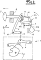
- an actuating device for a motor vehicle door lock 1 is shown.
- the motor vehicle door lock 1 has in its basic structure via a locking mechanism 2, 3 of the catch 2 and pawl 3.
- On the pawl 3 operates a release lever 4.
- the trigger lever 4 is connected via a flexible connecting means or a Bowden cable 5 to a lever 6, which is acted upon by a handle 7.
- the handle 7 passes through a door 8 in an outer door panel of a motor vehicle door, not shown. Consequently, it is in the handle 7 to an outside door handle, although of course, an internal door handle can be constructed comparable.
- An operator can act on the handle 7 pulling in the direction of the arrow shown in the figures. After the pulling action, the handle 7 returns to its original position. This is ensured by a return spring, not shown.
- the original position is shown pulled through, whereas the deflected position of the handle 7 is indicated by dash-dotted lines.
- the Fig. 2 now shows the deflected position of the handle 7 in normal operation.
- a locking lever 10 additionally belongs to the basic construction of the actuating device.
- the locking lever 10 sets the handle 7 when acceleration forces occur a given size, for example in an accident, ineffective.
- the acceleration forces in question are indicated by an arrow in the figures a marked and correspond in the present case to a side impact, which of course is not to be understood as limiting.
- the locking lever 10 in such a side impact or generally in the blocking operation that the handle 7 is blocked.
- This process is based on the Fig. 1 clearly showing the original position drawn through.
- the deflected position of the handle 7 is shown pulled through in normal operation. For this corresponds the dot-dashed representation in the Fig. 1 ,
- the locking lever 10 is designed in the embodiment as a three-armed lever.
- the locking lever 10 has a stop arm 10a, which interacts with the handle 7 or can interact.
- the stop arm 10a is L-shaped and can interact with a projection 11 on the handle 7 as described.
- the locking lever 10 also has an inertia arm 10b, which is equipped with an inertial mass 12.
- the inertial mass 12 can be found at the end of the inertia arm 10b in order to be able to build up a maximum torque in the blocking operation with respect to a rotation axis 13 for the locking lever 10 which is pivotable relative thereto.
- the locking lever 10 also has a coupling arm 10c, with the aid of the locking lever 10 is connected to the handle 7, and permanently elastic.
- the coupling arm 10c and the handle 7 by means of a spring 14 are interconnected.
- the further return spring 9 engages the locking lever 10, more precisely on the inertial arm 10b.
- any other return device 9 can be realized instead of the return spring 9, which is for a provision of the locking lever 10 in the in Fig. 1 illustrated original position ensures.
- a stop 15 for the locking lever 10 which defines the rest position of the locking lever 10.
- the stop 15 is designed stationary and may for example be defined in the interior of the unspecified motor vehicle door.
- the stop 15 is an inertia stop 15, which by acceleration forces a conditional deflections of the locking lever 10 and pivotal movements of the locking lever 10 is limited about its axis of rotation 13.
- the operation is as follows. Starting from the pulled in the Fig. 1 illustrated original position of the actuator performs an action on the handle 7 in normal operation to the fact that the handle 7 is deflected relative to its associated guide 8 or issued. This is dot-dashed in the Fig. 1 and pulled through in the Fig. 2 shown. Due to the deflection of the handle 7 of the locking lever 10 is taken. This causes primarily the handle 7 with the locking lever 10 coupling spring 14. In any case, the application of the handle 7 in normal operation causes the locking lever 10 in the transition from the Fig. 1 to Fig. 2 is pivoted about its axis of rotation 13 in the counterclockwise direction. In this process, the inertial mass 12 moves away from its associated inertia stop 15 and the locking lever 10 releases the handle 7 after a certain angle of rotation.
- the return spring 9 ensures that the locking lever 10 again in his Fig. 1 shown by the original position, likewise the handle 7 by a return spring, not shown.
- the inertial mass 12 is then again on the inertia stop 15. That is, each act on the handle 7 corresponds to the fact that the locking lever 10 undergoes the described deflection respectively a pivoting movement about its axis of rotation 13.
- the handle 7 primarily ensures that the transmission lever 6 about its axis 16 also in the counterclockwise direction is pivoted.
- the Bowden cable 5 connected to the transmission lever 6 is pulled pulling and pivots the release lever 4 in a clockwise direction, so that it can lift the pawl 3 of the catch 2.
- the catch 2 is released from the pawl 3 and also releases a previously captured locking pin. This is the normal functionality in the "open" operation of the motor vehicle door lock 1.
- the locking lever 10 ensures that the handle 7 is blocked in this blocking operation. Because the acceleration forces in question a primarily act on the inertial mass 12 and ensure that the locking lever 10 and the inertial mass 12 are pressed against the associated inertia stopper 15. In this way, the locking lever 10 is able to hold the handle 7 also. Because even at the handle 7 attack corresponding acceleration forces.
- the design is such that the handle 7 undergoes only a slight deflection relative to the locking lever 10, which is limited by the spring 14 with the locking lever 10 coupling spring 14.
- the stop arm 10a in addition to the projection 11 on the handle 7 can additionally provide for the described blockage of the handle 7 in the locked mode.
Landscapes
- Lock And Its Accessories (AREA)
Claims (15)
- Dispositif d'actionnement pour une serrure de portière de véhicule à moteur (1), comprenant une poignée (7) et un levier de blocage (10), qui rend la poignée (7) inopérante, si des forces d'accélération d'intensité prédéterminée se produisent, par exemple pendant un accident, le levier de blocage (10), en fonctionnement normal, subissant une déviation, si la poignée est actionnée, et ne rendant la poignée (7) inopérante qu'en mode bloqué, caractérisé en ce que la poignée (7) et le levier de blocage (10) sont couplés constamment l'un à l'autre de manière élastique.
- Dispositif d'actionnement selon la revendication 1, caractérisé en ce qu'en mode bloqué le levier de blocage (10) bloque la poignée (7).
- Dispositif d'actionnement selon la revendication 1 ou la revendication 2, caractérisé en ce que le levier de blocage (10) est pivotant autour d'un axe de rotation (13).
- Dispositif d'actionnement selon l'une des revendications 1 à 3, caractérisé en ce que le levier de blocage (10) est équipé d'au moins une masse d'inertie (12).
- Dispositif d'actionnement selon l'une des revendications 1 à 4, caractérisé en ce que le levier de blocage (10) est équipé d'au moins un bras de butée (10a), qui interagit éventuellement avec la poignée (7), et d'un bras d'inertie (10b) comprenant la masse d'inertie (12).
- Dispositif d'actionnement selon la revendication 5, caractérisé en ce que la masse d'inertie (12) est raccordée à l'extrémité au bras d'inertie (10b).
- Dispositif d'actionnement selon la revendication 5 ou la revendication 6, caractérisé en ce que le bras de butée (10a) interagit éventuellement avec une saillie (11) sur la poignée (7).
- Dispositif d'actionnement selon l'une des revendications 1 à 7, caractérisé en ce que le levier de blocage (10) comprend supplémentairement un bras de couplage (10c) raccordé à la poignée (7).
- Dispositif d'actionnement selon la revendication 1, caractérisé en ce que le bras de couplage (10c) est relié à la poignée (7) par moyen d'un ressort (14).
- Dispositif d'actionnement selon la revendication 9, caractérisé en ce que le ressort (14) comprend une constante de ressort adaptée à des forces d'inertie développées par la poignée (7).
- Dispositif d'actionnement selon l'une des revendications 1 à 10, caractérisé en ce que le levier de blocage (10) est muni d'un dispositif de rappel (9).
- Dispositif d'actionnement selon la revendication 11, caractérisé en ce que le dispositif de rappel (9) est configuré comme un ressort de rappel (9).
- Dispositif d'actionnement selon la revendication 11 ou la revendication 12, caractérisé en ce que le dispositif de rappel (9) s'engage dans le bras d'inertie (10b).
- Dispositif d'actionnement selon l'une des revendications 1 à 13, caractérisé en ce qu'une butée (15) est prévue pour le levier de blocage (10).
- Dispositif d'actionnement selon la revendication 14, caractérisé en ce que la butée (15) est configurée comme une butée d'inertie (15) et elle limite des déplacements du levier de blocage (10) causés par des forces d'accélération.
Applications Claiming Priority (2)
| Application Number | Priority Date | Filing Date | Title |
|---|---|---|---|
| DE201120106661 DE202011106661U1 (de) | 2011-10-12 | 2011-10-12 | Betätigungseinrichtung für ein Kraftfahrzeug-Türschloss |
| PCT/DE2012/000977 WO2013053346A1 (fr) | 2011-10-12 | 2012-10-05 | Dispositif de commande pour une serrure de portière d'un véhicule automobile |
Publications (2)
| Publication Number | Publication Date |
|---|---|
| EP2766543A1 EP2766543A1 (fr) | 2014-08-20 |
| EP2766543B1 true EP2766543B1 (fr) | 2018-01-17 |
Family
ID=47428448
Family Applications (1)
| Application Number | Title | Priority Date | Filing Date |
|---|---|---|---|
| EP12805566.2A Active EP2766543B1 (fr) | 2011-10-12 | 2012-10-05 | Dispositif de commande pour une serrure de portière d'un véhicule automobile |
Country Status (4)
| Country | Link |
|---|---|
| US (1) | US9637953B2 (fr) |
| EP (1) | EP2766543B1 (fr) |
| DE (1) | DE202011106661U1 (fr) |
| WO (1) | WO2013053346A1 (fr) |
Families Citing this family (32)
| Publication number | Priority date | Publication date | Assignee | Title |
|---|---|---|---|---|
| DE202009017667U1 (de) | 2009-12-26 | 2011-05-05 | BROSE SCHLIEßSYSTEME GMBH & CO. KG | Kraftfahrzeugschlossanordnung |
| DE102011051617A1 (de) * | 2011-07-06 | 2013-01-10 | Huf Hülsbeck & Fürst Gmbh & Co. Kg | Sichere Türgriffeinheit |
| JP6112774B2 (ja) | 2012-04-24 | 2017-04-12 | スズキ株式会社 | 自動車のドアハンドル構造 |
| US9404292B2 (en) * | 2012-07-11 | 2016-08-02 | Huf North America Automotive Parts Mfg. Corp. | Vehicular door handle assembly with deployable latch connection |
| US9394729B2 (en) * | 2012-07-11 | 2016-07-19 | Huf North America Automotive Parts Mfg. Corp. | Vehicular door handle assembly with electrically deployable latch connection |
| WO2014027099A1 (fr) * | 2012-08-16 | 2014-02-20 | Huf Hülsbeck & Fürst Gmbh & Co. Kg | Unité poignée de porte à fonction de sécurité |
| EP2735676B1 (fr) * | 2012-11-20 | 2017-02-15 | U-Shin Italia S.p.A. | Ensemble de poignée de panneau de véhicule |
| US9920555B2 (en) * | 2013-01-18 | 2018-03-20 | Kiekert Ag | Lock for a motor vehicle |
| US9593511B2 (en) * | 2013-03-27 | 2017-03-14 | Kiekert Ag | Lock for a motor vehicle |
| DE102013106176A1 (de) * | 2013-06-13 | 2014-12-18 | Huf Hülsbeck & Fürst Gmbh & Co. Kg | Türgriffanordnung für ein Kraftfahrzeug |
| JP6066078B2 (ja) * | 2013-06-21 | 2017-01-25 | アイシン精機株式会社 | 車両のドアアウタハンドル構造 |
| DE102013106610A1 (de) * | 2013-06-25 | 2015-01-08 | Huf Hülsbeck & Fürst Gmbh & Co. Kg | Türgriffanordnung für ein Kraftfahrzeug |
| DE102013110753A1 (de) * | 2013-09-27 | 2015-04-02 | Kiekert Aktiengesellschaft | Kraftfahrzeugtürschloss |
| DE102013110752A1 (de) * | 2013-09-27 | 2015-04-02 | Kiekert Aktiengesellschaft | Kraftfahrzeugtürschloss |
| DE102013112706A1 (de) * | 2013-11-18 | 2015-05-21 | Illinois Tool Works Inc. | System aus einem Türgriff und einer Betätigungseinrichtung für den Türgriff |
| KR101481352B1 (ko) * | 2013-12-19 | 2015-01-12 | 현대자동차주식회사 | 도어 아웃사이드핸들 |
| US9611675B2 (en) * | 2014-05-23 | 2017-04-04 | Brose Schliesssysteme Gmbh & Co. Kg | Motor vehicle door lock arrangement |
| DE102014004550A1 (de) * | 2014-03-31 | 2015-10-01 | Kiekert Aktiengesellschaft | Betätigungseinrichtung für ein Kraftfahrzeugschloss |
| DE102014004552A1 (de) * | 2014-03-31 | 2015-10-01 | Kiekert Aktiengesellschaft | Betätigungseinrichtung für ein Kraftfahrzeugschloss |
| US9810006B2 (en) * | 2014-06-04 | 2017-11-07 | Ford Global Technologies, Llc | Low effort outside release handle |
| EP2980341B1 (fr) | 2014-07-31 | 2019-11-06 | Brose Schliesssysteme GmbH & Co. KG | Agencement de serrure de portière de véhicule automobile |
| KR101628499B1 (ko) * | 2014-10-17 | 2016-06-21 | 현대자동차주식회사 | 측면 충돌시 도어 열림이 방지되는 구조 및 그 방법 |
| US10024083B2 (en) * | 2014-12-05 | 2018-07-17 | Ford Global Technologies, Llc | Vehicle door latch with inertial lock |
| WO2016095883A1 (fr) * | 2014-12-18 | 2016-06-23 | Kiekert Ag | Unité de verrouillage pour véhicule automobile |
| US10526818B2 (en) * | 2015-03-06 | 2020-01-07 | Brose Schliesssysteme Gmbh & Co. Kommanditgesellschaft | Motor vehicle lock |
| US20160258194A1 (en) * | 2015-03-06 | 2016-09-08 | Brose Schliesssysteme Gmbh & Co. Kg | Motor vehicle lock |
| WO2017158416A1 (fr) * | 2016-03-16 | 2017-09-21 | Klekert Ag | Dispositif d'ouverture doté d'un dispositif de verrouillage pour un verrou de véhicule à moteur |
| US10422167B2 (en) * | 2017-04-13 | 2019-09-24 | Ford Global Technologies, Llc | Push/pull handle operating system for a motor vehicle door |
| DE102019117667A1 (de) * | 2019-07-01 | 2021-01-07 | Kiekert Aktiengesellschaft | Kraftfahrzeug-Schloss, insbesondere Kraftfahrzeug-Türschloss |
| DE102019121233A1 (de) * | 2019-08-06 | 2021-02-11 | Kiekert Aktiengesellschaft | Kraftfahrzeug-schloss, insbesondere kraftfahrzeug-türschloss |
| DE102019121217A1 (de) * | 2019-08-06 | 2021-02-11 | Kiekert Aktiengesellschaft | Kraftfahrzeug-Schloss, insbesondere Kraftfahrzeug-Türschloss |
| US11873667B1 (en) * | 2019-08-07 | 2024-01-16 | Global Link Distribution, Corp. | Door handle and locking system |
Family Cites Families (23)
| Publication number | Priority date | Publication date | Assignee | Title |
|---|---|---|---|---|
| DE2023859C3 (de) | 1970-05-15 | 1978-10-19 | Daimler-Benz Ag, 7000 Stuttgart | Blockiervorrichtung für einen Kraftfahrzeugtürverschluß |
| JPS5527948B2 (fr) * | 1972-02-21 | 1980-07-24 | ||
| DE19610200A1 (de) * | 1996-03-15 | 1997-09-18 | Valeo Deutschland Gmbh & Co | Türaußengriff |
| DE19624640C1 (de) * | 1996-06-20 | 1998-01-08 | Kiekert Ag | Kraftfahrzeugtürverschluß mit Drehfalle, Sperrklinke und Blockiervorrichtung |
| DE19738492A1 (de) * | 1996-09-07 | 1998-03-12 | Volkswagen Ag | Kraftfahrzeugtürverschluß |
| US6042159A (en) * | 1997-08-01 | 2000-03-28 | Adac Plastics, Inc. | Door handle assembly |
| DE19758078C2 (de) * | 1997-12-30 | 2000-05-04 | Kiekert Ag | Kraftfahrzeugtürverschluß |
| DE19949119B4 (de) | 1999-01-20 | 2005-12-29 | Valeo Gmbh & Co Schliesssysteme Kg | Vorrichtung zur Verriegelung eines bewegbaren an einem Kraftfahrzeug angeordneten Teiles |
| DE19910513A1 (de) | 1999-03-10 | 2000-09-14 | Bayerische Motoren Werke Ag | Crash-Sperre am einem Türgriff oder Türschloß eines Kraftfahrzeugs |
| DE19929022C2 (de) * | 1999-06-25 | 2001-06-07 | Huf Huelsbeck & Fuerst Gmbh | Türaußengriff, insbesondere für Fahrzeuge |
| US6464270B1 (en) * | 2001-05-23 | 2002-10-15 | General Motors Corporation | Exterior handle assembly for motor vehicle door |
| DE10345104A1 (de) * | 2003-09-26 | 2005-04-21 | Kiekert Ag | Kraftfahrzeugtürverschluss |
| US7152893B2 (en) | 2004-08-23 | 2006-12-26 | Key Plastics, Llc | Handle assembly with dual latch feature |
| US7070216B2 (en) * | 2004-09-09 | 2006-07-04 | Siegel-Robert, Inc. | Vehicle door handle assembly |
| US8038185B2 (en) | 2005-08-01 | 2011-10-18 | Magna Closures Inc | Locking device |
| KR100737001B1 (ko) * | 2005-10-07 | 2007-07-09 | 현대자동차주식회사 | 차량 도어핸들어셈블리의 안전기구 |
| US7481468B2 (en) * | 2006-10-25 | 2009-01-27 | Ford Global Technologies, Llc | Apparatus for blocking the movement of an inertially activated component |
| DE102008034460A1 (de) * | 2008-06-27 | 2009-12-31 | Huf Hülsbeck & Fürst Gmbh & Co. Kg | Türaußengriff, insbesondere für Fahrzeuge |
| KR100957103B1 (ko) | 2008-06-30 | 2010-05-13 | 현대자동차주식회사 | 차량용 도어래치장치 |
| US8814231B2 (en) * | 2009-03-17 | 2014-08-26 | Toyota Motor Engineering & Manufacturing North America, Inc. | Adaptive door handles |
| DE102009058751A1 (de) * | 2009-11-06 | 2011-05-12 | Bayerische Motoren Werke Aktiengesellschaft | Betätigungseinrichtung für ein Türschloss einer Kraftfahrzeugtür |
| US8322077B2 (en) * | 2009-11-23 | 2012-12-04 | Ford Global Technologies, Llc | Vehicle door handle with inertia lock mechanism |
| US8366159B2 (en) * | 2010-01-06 | 2013-02-05 | Ford Global Technologies, Llc | Multi-lever bi-directional inertia catch mechanism |
-
2011
- 2011-10-12 DE DE201120106661 patent/DE202011106661U1/de not_active Expired - Lifetime
-
2012
- 2012-10-05 EP EP12805566.2A patent/EP2766543B1/fr active Active
- 2012-10-05 WO PCT/DE2012/000977 patent/WO2013053346A1/fr active Application Filing
- 2012-10-05 US US14/351,769 patent/US9637953B2/en active Active
Also Published As
| Publication number | Publication date |
|---|---|
| WO2013053346A1 (fr) | 2013-04-18 |
| US9637953B2 (en) | 2017-05-02 |
| EP2766543A1 (fr) | 2014-08-20 |
| US20140292005A1 (en) | 2014-10-02 |
| DE202011106661U1 (de) | 2013-01-16 |
Similar Documents
| Publication | Publication Date | Title |
|---|---|---|
| EP2766543B1 (fr) | Dispositif de commande pour une serrure de portière d'un véhicule automobile | |
| EP2766544B1 (fr) | Dispositif de commande d'une serrure de portière d'un véhicule automobile | |
| EP2673439B1 (fr) | Fermeture de portière de véhicule à moteur | |
| EP2633140B1 (fr) | Serrure de porte de véhicule automobile | |
| EP1101890B1 (fr) | Serrure de porte pour véhicule automobile | |
| EP2673437B1 (fr) | Fermeture de portière de véhicule à moteur | |
| EP2702218B1 (fr) | Système de fermeture de porte de véhicule automobile | |
| EP3049598B1 (fr) | Poignée de porte de véhicule automobile | |
| EP3126599B1 (fr) | Dispositif d'actionnement pour serrure de véhicule à moteur | |
| EP3445930B1 (fr) | Serrure de portière de véhicule automobile | |
| EP3126600A1 (fr) | Dispositif d'actionnement pour serrure de véhicule à moteur | |
| EP3060735B1 (fr) | Serrure de portière de véhicule automobile | |
| EP3583281A1 (fr) | Serrure de porte de véhicule automobile | |
| DE102011100090A1 (de) | Kraftfahrzeugtürverschluss | |
| EP3087236B1 (fr) | Serrure de portière de véhicule automobile | |
| EP2673438B1 (fr) | Fermeture de portière de véhicule à moteur | |
| EP3117057B1 (fr) | Système de fermeture de portière de véhicule automobile | |
| EP2235304B1 (fr) | Fermeture de portière de véhicule automobile | |
| WO2015043574A1 (fr) | Serrure de portière de véhicule automobile | |
| WO2020200361A1 (fr) | Serrure de porte d'un véhicule automobile | |
| WO2016206667A1 (fr) | Fermeture de porte de véhicule automobile | |
| DE102014006009A1 (de) | Kraftfahrzeugtürverschluss |
Legal Events
| Date | Code | Title | Description |
|---|---|---|---|
| PUAI | Public reference made under article 153(3) epc to a published international application that has entered the european phase |
Free format text: ORIGINAL CODE: 0009012 |
|
| 17P | Request for examination filed |
Effective date: 20140403 |
|
| AK | Designated contracting states |
Kind code of ref document: A1 Designated state(s): AL AT BE BG CH CY CZ DE DK EE ES FI FR GB GR HR HU IE IS IT LI LT LU LV MC MK MT NL NO PL PT RO RS SE SI SK SM TR |
|
| DAX | Request for extension of the european patent (deleted) | ||
| REG | Reference to a national code |
Ref country code: DE Ref legal event code: R079 Ref document number: 502012012041 Country of ref document: DE Free format text: PREVIOUS MAIN CLASS: E05B0007000000 Ipc: E05B0077060000 |
|
| RIC1 | Information provided on ipc code assigned before grant |
Ipc: E05B 77/06 20140101AFI20170629BHEP Ipc: E05B 85/10 20140101ALI20170629BHEP |
|
| GRAP | Despatch of communication of intention to grant a patent |
Free format text: ORIGINAL CODE: EPIDOSNIGR1 |
|
| INTG | Intention to grant announced |
Effective date: 20170906 |
|
| GRAS | Grant fee paid |
Free format text: ORIGINAL CODE: EPIDOSNIGR3 |
|
| GRAA | (expected) grant |
Free format text: ORIGINAL CODE: 0009210 |
|
| AK | Designated contracting states |
Kind code of ref document: B1 Designated state(s): AL AT BE BG CH CY CZ DE DK EE ES FI FR GB GR HR HU IE IS IT LI LT LU LV MC MK MT NL NO PL PT RO RS SE SI SK SM TR |
|
| REG | Reference to a national code |
Ref country code: GB Ref legal event code: FG4D Free format text: NOT ENGLISH |
|
| REG | Reference to a national code |
Ref country code: CH Ref legal event code: EP |
|
| REG | Reference to a national code |
Ref country code: IE Ref legal event code: FG4D Free format text: LANGUAGE OF EP DOCUMENT: GERMAN |
|
| REG | Reference to a national code |
Ref country code: AT Ref legal event code: REF Ref document number: 964539 Country of ref document: AT Kind code of ref document: T Effective date: 20180215 |
|
| REG | Reference to a national code |
Ref country code: DE Ref legal event code: R096 Ref document number: 502012012041 Country of ref document: DE |
|
| REG | Reference to a national code |
Ref country code: NL Ref legal event code: MP Effective date: 20180117 |
|
| REG | Reference to a national code |
Ref country code: LT Ref legal event code: MG4D |
|
| PG25 | Lapsed in a contracting state [announced via postgrant information from national office to epo] |
Ref country code: NL Free format text: LAPSE BECAUSE OF FAILURE TO SUBMIT A TRANSLATION OF THE DESCRIPTION OR TO PAY THE FEE WITHIN THE PRESCRIBED TIME-LIMIT Effective date: 20180117 |
|
| PG25 | Lapsed in a contracting state [announced via postgrant information from national office to epo] |
Ref country code: FI Free format text: LAPSE BECAUSE OF FAILURE TO SUBMIT A TRANSLATION OF THE DESCRIPTION OR TO PAY THE FEE WITHIN THE PRESCRIBED TIME-LIMIT Effective date: 20180117 Ref country code: CY Free format text: LAPSE BECAUSE OF FAILURE TO SUBMIT A TRANSLATION OF THE DESCRIPTION OR TO PAY THE FEE WITHIN THE PRESCRIBED TIME-LIMIT Effective date: 20180117 Ref country code: NO Free format text: LAPSE BECAUSE OF FAILURE TO SUBMIT A TRANSLATION OF THE DESCRIPTION OR TO PAY THE FEE WITHIN THE PRESCRIBED TIME-LIMIT Effective date: 20180417 Ref country code: HR Free format text: LAPSE BECAUSE OF FAILURE TO SUBMIT A TRANSLATION OF THE DESCRIPTION OR TO PAY THE FEE WITHIN THE PRESCRIBED TIME-LIMIT Effective date: 20180117 Ref country code: LT Free format text: LAPSE BECAUSE OF FAILURE TO SUBMIT A TRANSLATION OF THE DESCRIPTION OR TO PAY THE FEE WITHIN THE PRESCRIBED TIME-LIMIT Effective date: 20180117 Ref country code: ES Free format text: LAPSE BECAUSE OF FAILURE TO SUBMIT A TRANSLATION OF THE DESCRIPTION OR TO PAY THE FEE WITHIN THE PRESCRIBED TIME-LIMIT Effective date: 20180117 |
|
| PG25 | Lapsed in a contracting state [announced via postgrant information from national office to epo] |
Ref country code: IS Free format text: LAPSE BECAUSE OF FAILURE TO SUBMIT A TRANSLATION OF THE DESCRIPTION OR TO PAY THE FEE WITHIN THE PRESCRIBED TIME-LIMIT Effective date: 20180517 Ref country code: BG Free format text: LAPSE BECAUSE OF FAILURE TO SUBMIT A TRANSLATION OF THE DESCRIPTION OR TO PAY THE FEE WITHIN THE PRESCRIBED TIME-LIMIT Effective date: 20180417 Ref country code: RS Free format text: LAPSE BECAUSE OF FAILURE TO SUBMIT A TRANSLATION OF THE DESCRIPTION OR TO PAY THE FEE WITHIN THE PRESCRIBED TIME-LIMIT Effective date: 20180117 Ref country code: PL Free format text: LAPSE BECAUSE OF FAILURE TO SUBMIT A TRANSLATION OF THE DESCRIPTION OR TO PAY THE FEE WITHIN THE PRESCRIBED TIME-LIMIT Effective date: 20180117 Ref country code: SE Free format text: LAPSE BECAUSE OF FAILURE TO SUBMIT A TRANSLATION OF THE DESCRIPTION OR TO PAY THE FEE WITHIN THE PRESCRIBED TIME-LIMIT Effective date: 20180117 Ref country code: LV Free format text: LAPSE BECAUSE OF FAILURE TO SUBMIT A TRANSLATION OF THE DESCRIPTION OR TO PAY THE FEE WITHIN THE PRESCRIBED TIME-LIMIT Effective date: 20180117 Ref country code: GR Free format text: LAPSE BECAUSE OF FAILURE TO SUBMIT A TRANSLATION OF THE DESCRIPTION OR TO PAY THE FEE WITHIN THE PRESCRIBED TIME-LIMIT Effective date: 20180418 |
|
| PG25 | Lapsed in a contracting state [announced via postgrant information from national office to epo] |
Ref country code: MT Free format text: LAPSE BECAUSE OF FAILURE TO SUBMIT A TRANSLATION OF THE DESCRIPTION OR TO PAY THE FEE WITHIN THE PRESCRIBED TIME-LIMIT Effective date: 20180117 |
|
| REG | Reference to a national code |
Ref country code: DE Ref legal event code: R097 Ref document number: 502012012041 Country of ref document: DE |
|
| REG | Reference to a national code |
Ref country code: FR Ref legal event code: PLFP Year of fee payment: 7 |
|
| PG25 | Lapsed in a contracting state [announced via postgrant information from national office to epo] |
Ref country code: IT Free format text: LAPSE BECAUSE OF FAILURE TO SUBMIT A TRANSLATION OF THE DESCRIPTION OR TO PAY THE FEE WITHIN THE PRESCRIBED TIME-LIMIT Effective date: 20180117 Ref country code: EE Free format text: LAPSE BECAUSE OF FAILURE TO SUBMIT A TRANSLATION OF THE DESCRIPTION OR TO PAY THE FEE WITHIN THE PRESCRIBED TIME-LIMIT Effective date: 20180117 Ref country code: RO Free format text: LAPSE BECAUSE OF FAILURE TO SUBMIT A TRANSLATION OF THE DESCRIPTION OR TO PAY THE FEE WITHIN THE PRESCRIBED TIME-LIMIT Effective date: 20180117 Ref country code: AL Free format text: LAPSE BECAUSE OF FAILURE TO SUBMIT A TRANSLATION OF THE DESCRIPTION OR TO PAY THE FEE WITHIN THE PRESCRIBED TIME-LIMIT Effective date: 20180117 |
|
| PLBE | No opposition filed within time limit |
Free format text: ORIGINAL CODE: 0009261 |
|
| STAA | Information on the status of an ep patent application or granted ep patent |
Free format text: STATUS: NO OPPOSITION FILED WITHIN TIME LIMIT |
|
| PG25 | Lapsed in a contracting state [announced via postgrant information from national office to epo] |
Ref country code: DK Free format text: LAPSE BECAUSE OF FAILURE TO SUBMIT A TRANSLATION OF THE DESCRIPTION OR TO PAY THE FEE WITHIN THE PRESCRIBED TIME-LIMIT Effective date: 20180117 Ref country code: SK Free format text: LAPSE BECAUSE OF FAILURE TO SUBMIT A TRANSLATION OF THE DESCRIPTION OR TO PAY THE FEE WITHIN THE PRESCRIBED TIME-LIMIT Effective date: 20180117 Ref country code: SM Free format text: LAPSE BECAUSE OF FAILURE TO SUBMIT A TRANSLATION OF THE DESCRIPTION OR TO PAY THE FEE WITHIN THE PRESCRIBED TIME-LIMIT Effective date: 20180117 |
|
| 26N | No opposition filed |
Effective date: 20181018 |
|
| PG25 | Lapsed in a contracting state [announced via postgrant information from national office to epo] |
Ref country code: SI Free format text: LAPSE BECAUSE OF FAILURE TO SUBMIT A TRANSLATION OF THE DESCRIPTION OR TO PAY THE FEE WITHIN THE PRESCRIBED TIME-LIMIT Effective date: 20180117 |
|
| REG | Reference to a national code |
Ref country code: CH Ref legal event code: PL |
|
| GBPC | Gb: european patent ceased through non-payment of renewal fee |
Effective date: 20181005 |
|
| REG | Reference to a national code |
Ref country code: BE Ref legal event code: MM Effective date: 20181031 |
|
| PG25 | Lapsed in a contracting state [announced via postgrant information from national office to epo] |
Ref country code: MC Free format text: LAPSE BECAUSE OF FAILURE TO SUBMIT A TRANSLATION OF THE DESCRIPTION OR TO PAY THE FEE WITHIN THE PRESCRIBED TIME-LIMIT Effective date: 20180117 Ref country code: LU Free format text: LAPSE BECAUSE OF NON-PAYMENT OF DUE FEES Effective date: 20181005 |
|
| REG | Reference to a national code |
Ref country code: IE Ref legal event code: MM4A |
|
| PG25 | Lapsed in a contracting state [announced via postgrant information from national office to epo] |
Ref country code: LI Free format text: LAPSE BECAUSE OF NON-PAYMENT OF DUE FEES Effective date: 20181031 Ref country code: CH Free format text: LAPSE BECAUSE OF NON-PAYMENT OF DUE FEES Effective date: 20181031 Ref country code: BE Free format text: LAPSE BECAUSE OF NON-PAYMENT OF DUE FEES Effective date: 20181031 |
|
| PG25 | Lapsed in a contracting state [announced via postgrant information from national office to epo] |
Ref country code: IE Free format text: LAPSE BECAUSE OF NON-PAYMENT OF DUE FEES Effective date: 20181005 Ref country code: GB Free format text: LAPSE BECAUSE OF NON-PAYMENT OF DUE FEES Effective date: 20181005 |
|
| REG | Reference to a national code |
Ref country code: AT Ref legal event code: MM01 Ref document number: 964539 Country of ref document: AT Kind code of ref document: T Effective date: 20181005 |
|
| PG25 | Lapsed in a contracting state [announced via postgrant information from national office to epo] |
Ref country code: AT Free format text: LAPSE BECAUSE OF NON-PAYMENT OF DUE FEES Effective date: 20181005 |
|
| PG25 | Lapsed in a contracting state [announced via postgrant information from national office to epo] |
Ref country code: TR Free format text: LAPSE BECAUSE OF FAILURE TO SUBMIT A TRANSLATION OF THE DESCRIPTION OR TO PAY THE FEE WITHIN THE PRESCRIBED TIME-LIMIT Effective date: 20180117 |
|
| PG25 | Lapsed in a contracting state [announced via postgrant information from national office to epo] |
Ref country code: PT Free format text: LAPSE BECAUSE OF FAILURE TO SUBMIT A TRANSLATION OF THE DESCRIPTION OR TO PAY THE FEE WITHIN THE PRESCRIBED TIME-LIMIT Effective date: 20180117 |
|
| PG25 | Lapsed in a contracting state [announced via postgrant information from national office to epo] |
Ref country code: MK Free format text: LAPSE BECAUSE OF NON-PAYMENT OF DUE FEES Effective date: 20180117 Ref country code: HU Free format text: LAPSE BECAUSE OF FAILURE TO SUBMIT A TRANSLATION OF THE DESCRIPTION OR TO PAY THE FEE WITHIN THE PRESCRIBED TIME-LIMIT; INVALID AB INITIO Effective date: 20121005 |
|
| P01 | Opt-out of the competence of the unified patent court (upc) registered |
Effective date: 20230529 |
|
| PGFP | Annual fee paid to national office [announced via postgrant information from national office to epo] |
Ref country code: CZ Payment date: 20230926 Year of fee payment: 12 |
|
| PGFP | Annual fee paid to national office [announced via postgrant information from national office to epo] |
Ref country code: FR Payment date: 20231023 Year of fee payment: 12 Ref country code: DE Payment date: 20231018 Year of fee payment: 12 |