EP2766543B1 - Actuation device for a motor vehicle door lock - Google Patents
Actuation device for a motor vehicle door lock Download PDFInfo
- Publication number
- EP2766543B1 EP2766543B1 EP12805566.2A EP12805566A EP2766543B1 EP 2766543 B1 EP2766543 B1 EP 2766543B1 EP 12805566 A EP12805566 A EP 12805566A EP 2766543 B1 EP2766543 B1 EP 2766543B1
- Authority
- EP
- European Patent Office
- Prior art keywords
- handle
- actuation device
- locking lever
- detent lever
- arm
- Prior art date
- Legal status (The legal status is an assumption and is not a legal conclusion. Google has not performed a legal analysis and makes no representation as to the accuracy of the status listed.)
- Active
Links
- 230000001133 acceleration Effects 0.000 claims description 17
- 230000008878 coupling Effects 0.000 claims description 10
- 238000010168 coupling process Methods 0.000 claims description 10
- 238000005859 coupling reaction Methods 0.000 claims description 10
- 230000014759 maintenance of location Effects 0.000 claims 4
- 230000000903 blocking effect Effects 0.000 description 11
- 238000000034 method Methods 0.000 description 6
- 230000008569 process Effects 0.000 description 4
- 230000009471 action Effects 0.000 description 3
- 230000005540 biological transmission Effects 0.000 description 3
- 238000005260 corrosion Methods 0.000 description 2
- 230000007797 corrosion Effects 0.000 description 2
- 230000008859 change Effects 0.000 description 1
- 238000010276 construction Methods 0.000 description 1
- JEIPFZHSYJVQDO-UHFFFAOYSA-N iron(III) oxide Inorganic materials O=[Fe]O[Fe]=O JEIPFZHSYJVQDO-UHFFFAOYSA-N 0.000 description 1
- 230000007246 mechanism Effects 0.000 description 1
- 230000007704 transition Effects 0.000 description 1
Images

Classifications
-
- E—FIXED CONSTRUCTIONS
- E05—LOCKS; KEYS; WINDOW OR DOOR FITTINGS; SAFES
- E05B—LOCKS; ACCESSORIES THEREFOR; HANDCUFFS
- E05B77/00—Vehicle locks characterised by special functions or purposes
- E05B77/02—Vehicle locks characterised by special functions or purposes for accident situations
- E05B77/04—Preventing unwanted lock actuation, e.g. unlatching, at the moment of collision
- E05B77/06—Preventing unwanted lock actuation, e.g. unlatching, at the moment of collision by means of inertial forces
-
- E—FIXED CONSTRUCTIONS
- E05—LOCKS; KEYS; WINDOW OR DOOR FITTINGS; SAFES
- E05B—LOCKS; ACCESSORIES THEREFOR; HANDCUFFS
- E05B85/00—Details of vehicle locks not provided for in groups E05B77/00 - E05B83/00
- E05B85/10—Handles
-
- Y—GENERAL TAGGING OF NEW TECHNOLOGICAL DEVELOPMENTS; GENERAL TAGGING OF CROSS-SECTIONAL TECHNOLOGIES SPANNING OVER SEVERAL SECTIONS OF THE IPC; TECHNICAL SUBJECTS COVERED BY FORMER USPC CROSS-REFERENCE ART COLLECTIONS [XRACs] AND DIGESTS
- Y10—TECHNICAL SUBJECTS COVERED BY FORMER USPC
- Y10T—TECHNICAL SUBJECTS COVERED BY FORMER US CLASSIFICATION
- Y10T292/00—Closure fasteners
- Y10T292/57—Operators with knobs or handles
Definitions
- the invention relates to an actuating device for a motor vehicle door lock, with a handle, and with a locking lever, which sets the handle at occurring acceleration forces of predetermined size, for example in an accident, ineffective.
- the actuating device is usually mechanically coupled via a connecting means, for example a Bowden cable, an actuating rod, etc. with the motor vehicle door lock.
- a connecting means for example a Bowden cable, an actuating rod, etc.
- a release lever in the interior of the motor vehicle door lock can be acted upon with the aid of the handle in the simplest case.
- This release lever regularly lifts a pawl from a catch, so that the catch opens spring-assisted and releases a previously captured locking pin.
- the motor vehicle door lock is opened and it can also be an associated vehicle door swung open or otherwise opened.
- the locking lever sets the handle ineffective associated with an accident occurring acceleration forces of predetermined size. That is, the respective acceleration forces do not cause due to the action of the locking lever that the motor vehicle door lock is opened unintentionally.
- the locking lever sets the handle ineffective associated with an accident occurring acceleration forces of predetermined size. That is, the respective acceleration forces do not cause due to the action of the locking lever that the motor vehicle door lock is opened unintentionally.
- persons located in the interior of a motor vehicle body obtain maximum protection and can, in particular, deploy maximum safety here, such as side impact protection, airbag, etc.
- the control works in turn on a securing part, which engages in a crash in a groove-shaped recess and thereby blocks the handle.
- the invention is based on the technical problem of further developing such an actuating device for a motor vehicle door lock of the structure described at the beginning in such a way that a permanent and in particular still guaranteed functional reliability is observed.
- a generic actuator within the scope of the invention is characterized in that the handle and the locking lever are permanently elastically coupled with each other.
- the normal operation thus corresponds to the fact that the locking lever undergoes a deflection when the handle is acted upon. Normal operation means that, for example, do not attack any acceleration forces associated with an accident.
- each actuation of the handle corresponds to the fact that at the same time the locking lever is deflected.
- the locking lever is also deflected at the same time.
- the locking lever in lock-up mode which is typically in Acceleration forces associated with an accident, now ensures that the handle is ineffective in its function. That is, any attacking on the handle also acceleration forces do not cause the release lever is actuated in the connected motor vehicle door lock. An associated motor vehicle door is logically not opened unintentionally.
- the ineffectiveness of the handle in the blocking operation can be set up so that the handle with respect to the release lever in question performs or perform an idle stroke quasi, which is initiated by the locking lever in the blocking mode.
- the procedure is such that the blocking lever blocks the handle in blocking operation.
- the locking lever is advantageously equipped with at least one inertial mass.
- the locking lever is usually a two-arm lever and in particular even a three-arm lever.
- the locking lever has at least one with the handle optionally interacting stop arm and the inertial mass having inertial arm.
- the inertial mass having inertial arm.
- the inertial mass is connected to the end of the inertial arm. Since the locking lever is mounted in total rotatable about an axis of rotation, for example, in the interior of a motor vehicle door, significant torques can be built up and observed in the event of a crash with the aid of the inertial mass connected to the end of the inertial arm.
- the handle and the locking lever according to the invention are permanently elastically coupled together.
- the coupling arm can be connected by means of a spring with the handle.
- the spring is usually designed so that it has a spring constant which is adapted to the inertial forces built up by the handle.
- the locking lever is additionally equipped with a return device, which transfers him back to its original position after its rotatable deflection by an operation of the handle.
- the return device may be a return spring.
- the reset device can also be controlled mechanically.
- the interpretation is usually made so that the restoring device acts on the inertial arm.
- the locking lever is typically associated with a stop.
- the stop is designed as an inertia stop. As a result, the stop or inertial stop can be limited by acceleration-induced deflections of the blocking lever.
- the handle ensures that the locking lever is deflected against the restoring force built up by the return spring. Since no significant forces act on the inertial mass in normal operation, this process corresponds to the fact that the locking lever performs a pivoting movement about its axis of rotation caused by the handle. In this process, the handle may take the locking lever on the spring and the coupling arm.
- the spring constant of this spring is designed so that the handle experiences only a slight deflection, at least the projection on the handle does not run against the stop arm of the locking lever. In principle, however, this can also be allowed to ensure additional fixation of the handle by means of the locking lever. In any case, the handle is blocked in the blocking mode by means of the locking lever. As a result, the trigger lever connected to the handle in the motor vehicle door lock can not be acted upon unintentionally, so that the motor vehicle door lock keeps its position "closed" unchanged.
- the main benefits are the main benefits.
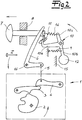
- an actuating device for a motor vehicle door lock 1 is shown.
- the motor vehicle door lock 1 has in its basic structure via a locking mechanism 2, 3 of the catch 2 and pawl 3.
- On the pawl 3 operates a release lever 4.
- the trigger lever 4 is connected via a flexible connecting means or a Bowden cable 5 to a lever 6, which is acted upon by a handle 7.
- the handle 7 passes through a door 8 in an outer door panel of a motor vehicle door, not shown. Consequently, it is in the handle 7 to an outside door handle, although of course, an internal door handle can be constructed comparable.
- An operator can act on the handle 7 pulling in the direction of the arrow shown in the figures. After the pulling action, the handle 7 returns to its original position. This is ensured by a return spring, not shown.
- the original position is shown pulled through, whereas the deflected position of the handle 7 is indicated by dash-dotted lines.
- the Fig. 2 now shows the deflected position of the handle 7 in normal operation.
- a locking lever 10 additionally belongs to the basic construction of the actuating device.
- the locking lever 10 sets the handle 7 when acceleration forces occur a given size, for example in an accident, ineffective.
- the acceleration forces in question are indicated by an arrow in the figures a marked and correspond in the present case to a side impact, which of course is not to be understood as limiting.
- the locking lever 10 in such a side impact or generally in the blocking operation that the handle 7 is blocked.
- This process is based on the Fig. 1 clearly showing the original position drawn through.
- the deflected position of the handle 7 is shown pulled through in normal operation. For this corresponds the dot-dashed representation in the Fig. 1 ,
- the locking lever 10 is designed in the embodiment as a three-armed lever.
- the locking lever 10 has a stop arm 10a, which interacts with the handle 7 or can interact.
- the stop arm 10a is L-shaped and can interact with a projection 11 on the handle 7 as described.
- the locking lever 10 also has an inertia arm 10b, which is equipped with an inertial mass 12.
- the inertial mass 12 can be found at the end of the inertia arm 10b in order to be able to build up a maximum torque in the blocking operation with respect to a rotation axis 13 for the locking lever 10 which is pivotable relative thereto.
- the locking lever 10 also has a coupling arm 10c, with the aid of the locking lever 10 is connected to the handle 7, and permanently elastic.
- the coupling arm 10c and the handle 7 by means of a spring 14 are interconnected.
- the further return spring 9 engages the locking lever 10, more precisely on the inertial arm 10b.
- any other return device 9 can be realized instead of the return spring 9, which is for a provision of the locking lever 10 in the in Fig. 1 illustrated original position ensures.
- a stop 15 for the locking lever 10 which defines the rest position of the locking lever 10.
- the stop 15 is designed stationary and may for example be defined in the interior of the unspecified motor vehicle door.
- the stop 15 is an inertia stop 15, which by acceleration forces a conditional deflections of the locking lever 10 and pivotal movements of the locking lever 10 is limited about its axis of rotation 13.
- the operation is as follows. Starting from the pulled in the Fig. 1 illustrated original position of the actuator performs an action on the handle 7 in normal operation to the fact that the handle 7 is deflected relative to its associated guide 8 or issued. This is dot-dashed in the Fig. 1 and pulled through in the Fig. 2 shown. Due to the deflection of the handle 7 of the locking lever 10 is taken. This causes primarily the handle 7 with the locking lever 10 coupling spring 14. In any case, the application of the handle 7 in normal operation causes the locking lever 10 in the transition from the Fig. 1 to Fig. 2 is pivoted about its axis of rotation 13 in the counterclockwise direction. In this process, the inertial mass 12 moves away from its associated inertia stop 15 and the locking lever 10 releases the handle 7 after a certain angle of rotation.
- the return spring 9 ensures that the locking lever 10 again in his Fig. 1 shown by the original position, likewise the handle 7 by a return spring, not shown.
- the inertial mass 12 is then again on the inertia stop 15. That is, each act on the handle 7 corresponds to the fact that the locking lever 10 undergoes the described deflection respectively a pivoting movement about its axis of rotation 13.
- the handle 7 primarily ensures that the transmission lever 6 about its axis 16 also in the counterclockwise direction is pivoted.
- the Bowden cable 5 connected to the transmission lever 6 is pulled pulling and pivots the release lever 4 in a clockwise direction, so that it can lift the pawl 3 of the catch 2.
- the catch 2 is released from the pawl 3 and also releases a previously captured locking pin. This is the normal functionality in the "open" operation of the motor vehicle door lock 1.
- the locking lever 10 ensures that the handle 7 is blocked in this blocking operation. Because the acceleration forces in question a primarily act on the inertial mass 12 and ensure that the locking lever 10 and the inertial mass 12 are pressed against the associated inertia stopper 15. In this way, the locking lever 10 is able to hold the handle 7 also. Because even at the handle 7 attack corresponding acceleration forces.
- the design is such that the handle 7 undergoes only a slight deflection relative to the locking lever 10, which is limited by the spring 14 with the locking lever 10 coupling spring 14.
- the stop arm 10a in addition to the projection 11 on the handle 7 can additionally provide for the described blockage of the handle 7 in the locked mode.
Landscapes
- Lock And Its Accessories (AREA)
Description
Die Erfindung betrifft eine Betätigungseinrichtung für ein Kraftfahrzeug-Türschloss, mit einer Handhabe, und mit einem Sperrhebel, welcher die Handhabe bei auftretenden Beschleunigungskräften vorgegebener Größe, beispielsweise bei einem Unfall, unwirksam setzt.The invention relates to an actuating device for a motor vehicle door lock, with a handle, and with a locking lever, which sets the handle at occurring acceleration forces of predetermined size, for example in an accident, ineffective.
Die Betätigungseinrichtung ist üblicherweise über ein Verbindungsmittel, beispielsweise einen Bowdenzug, eine Betätigungsstange etc. mit dem Kraftfahrzeug-Türschloss mechanisch gekoppelt. Dadurch kann mit Hilfe der Handhabe im einfachsten Fall ein Auslösehebel im Innern des Kraftfahrzeug-Türschlosses beaufschlagt werden. Dieser Auslösehebel hebt regelmäßig eine Sperrklinke von einer Drehfalle ab, so dass die Drehfalle federunterstützt öffnet und einen zuvor gefangenen Schließbolzen freigibt. Als Folge hiervon wird das Kraftfahrzeug-Türschloss geöffnet und es kann ebenso eine zugehörige Kraftfahrzeugtür aufgeschwenkt oder sonst wie geöffnet werden.The actuating device is usually mechanically coupled via a connecting means, for example a Bowden cable, an actuating rod, etc. with the motor vehicle door lock. As a result, a release lever in the interior of the motor vehicle door lock can be acted upon with the aid of the handle in the simplest case. This release lever regularly lifts a pawl from a catch, so that the catch opens spring-assisted and releases a previously captured locking pin. As a result, the motor vehicle door lock is opened and it can also be an associated vehicle door swung open or otherwise opened.
Um eine unbeabsichtigte Öffnung beispielsweise bei einem Unfall zu verhindern, ist der Sperrhebel vorgesehen. Zu diesem Zweck setzt der Sperrhebel die Handhabe bei mit einem Unfall verbundenen auftretenden Beschleunigungskräften vorgegebener Größe unwirksam. Das heißt, die betreffenden Beschleunigungskräfte führen infolge der Wirkung des Sperrhebels nicht dazu, dass das Kraftfahrzeug-Türschloss unbeabsichtigt geöffnet wird. Dadurch erfahren im Innern einer Kraftfahrzeugkarosserie befindliche Personen einen maximalen Schutz und können insbesondere hier vorhandene Sicherheitseinrichtungen, wie Seitenaufprallschutz, Airbag etc. maximale Wirkung entfalten.To prevent inadvertent opening, for example in an accident, the locking lever is provided. For this purpose, the locking lever sets the handle ineffective associated with an accident occurring acceleration forces of predetermined size. That is, the respective acceleration forces do not cause due to the action of the locking lever that the motor vehicle door lock is opened unintentionally. As a result, persons located in the interior of a motor vehicle body obtain maximum protection and can, in particular, deploy maximum safety here, such as side impact protection, airbag, etc.
Im gattungsbildenden Stand der Technik nach der
Das Steuerelement arbeitet seinerseits auf ein Sicherungsteil, welches im Crashfall in eine nutenförmige Ausnehmung eingreift und dadurch die Handhabe blockiert.The control works in turn on a securing part, which engages in a crash in a groove-shaped recess and thereby blocks the handle.
Ähnlich geht der Stand der Technik nach der ebenfalls gattungsbildenden
Erwähnenswert ist schließlich noch das in der
Der Stand der Technik hat sich grundsätzlich bewährt, stößt allerdings dann an Grenzen, wenn der Sperrhebel lange Zeit nicht betätigt worden ist. Tatsächlich beobachtet man heutzutage eine zunehmende Lebensdauer der Kraftfahrzeuge, die oftmals ein Alter von deutlich mehr als 10 Jahren erreichen. Hier ist es im Rahmen der bisher verfolgten Maßnahmen schwierig, nach wie vor die Funktionsfähigkeit des Sperrhebels sicherzustellen. Denn dieser ist typischerweise im Bereich eines Außentürgriffes respektive einer dort angeordneten Betätigungseinrichtung platziert und somit Wettereinflüssen, Korrosion etc. mehr oder minder stark ausgesetzt. Bei einer solchen Auslegung kann nicht sichergestellt werden, dass auch noch nach Jahren die gewünschte und einwandfreie Funktionalität beobachtet wird und die Kraftfahrzeuginsassen optimalen Schutz bei einem Unfall erfahren. Hier will die Erfindung insgesamt Abhilfe schaffen. Im gattungsbildenden Stand der Technik nach der
Der Erfindung liegt das technische Problem zugrunde, eine derartige Betätigungseinrichtung für ein Kraftfahrzeug-Türschloss des eingangs beschriebenen Aufbaus so weiter zu entwickeln, dass eine dauerhafte und insbesondere noch nach Jahren gewährleistete Funktionssicherheit beobachtet wird.The invention is based on the technical problem of further developing such an actuating device for a motor vehicle door lock of the structure described at the beginning in such a way that a permanent and in particular still guaranteed functional reliability is observed.
Zur Lösung dieser technischen Problemstellung ist eine gattungsgemäße Betätigungseinrichtung im Rahmen der Erfindung dadurch gekennzeichnet, dass die Handhabe und der Sperrhebel dauerhaft elastisch miteiander gekoppelt sind. Erfindungsgemäß korrespondiert der Normalbetrieb also dazu, dass der Sperrhebel bei einer Beaufschlagung der Handhabe eine Auslenkung erfährt. Normalbetrieb bedeutet dabei, dass keine beispielsweise mit einem Unfall einhergehende Beschleunigungskräfte angreifen. Im Regelfall korrespondiert also jede Betätigung der Handhabe dazu, dass zugleich auch der Sperrhebel ausgelenkt wird. Jedes mal wenn also beispielsweise der Außentürgriff bzw. die dort vorgesehene Handhabe von einem Bediener zum Öffnen der zugehörigen Kraftfahrzeugtür gezogen oder sonst wie beaufschlagt wird, wird zugleich auch der Sperrhebel ausgelenkt. Dadurch ist sichergestellt, dass etwaige Lager für den meistens drehbar gelagerten Sperrhebel nicht mit der Zeit durch beispielsweise Korrosion "festbacken" oder im schlimmsten Fall sogar "festrosten" können. Vielmehr sorgt die ständige und regelmäßige Beaufschlagung des Sperrhebels dafür, dass dieser seine Funktion auch bei hoher Lebensdauer des Kraftfahrzeuges und folglich des zugehörigen Türschlosses wie der Betätigungseinrichtung beibehält.To solve this technical problem, a generic actuator within the scope of the invention is characterized in that the handle and the locking lever are permanently elastically coupled with each other. According to the invention, the normal operation thus corresponds to the fact that the locking lever undergoes a deflection when the handle is acted upon. Normal operation means that, for example, do not attack any acceleration forces associated with an accident. As a rule, therefore, each actuation of the handle corresponds to the fact that at the same time the locking lever is deflected. Each time when, for example, the outer door handle or the handle provided there is pulled or otherwise acted upon by an operator to open the associated motor vehicle door, the locking lever is also deflected at the same time. This ensures that any bearing for the usually rotatably mounted locking lever can not "caking" with time by, for example, corrosion, or even "rust down" in the worst case. Rather, the constant and regular loading of the locking lever ensures that this function even at high durability of Motor vehicle and thus the associated door lock as the actuator maintains.
Im Detail sorgt der Sperrhebel im Sperrbetrieb, das heißt typischerweise bei mit einem Unfall verbundenen Beschleunigungskräften, nun dafür, dass die Handhabe in ihrer Funktion unwirksam wird. Das heißt, etwaige an der Handhabe ebenfalls angreifende Beschleunigungskräfte führen nicht dazu, dass der Auslösehebel im angeschlossenen Kraftfahrzeug-Türschloss betätigt wird. Eine zugehörige Kraftfahrzeugtür wird folgerichtig nicht unbeabsichtigt geöffnet.In detail, the locking lever in lock-up mode, which is typically in Acceleration forces associated with an accident, now ensures that the handle is ineffective in its function. That is, any attacking on the handle also acceleration forces do not cause the release lever is actuated in the connected motor vehicle door lock. An associated motor vehicle door is logically not opened unintentionally.
Die Unwirksamkeit der Handhabe im Sperrbetrieb kann dabei so eingerichtet werden, dass die Handhabe mit Bezug zu dem fraglichen Auslösehebel quasi einen Leerhub vollführt oder vollführen kann, welcher vom Sperrhebel im Sperrbetrieb initiiert wird. Im Regelfall wird jedoch so vorgegangen, dass der Sperrhebel im Sperrbetrieb die Handhabe blockiert. Zu diesem Zweck ist der Sperrhebel vorteilhaft mit wenigstens einer Trägheitsmasse ausgerüstet.The ineffectiveness of the handle in the blocking operation can be set up so that the handle with respect to the release lever in question performs or perform an idle stroke quasi, which is initiated by the locking lever in the blocking mode. As a rule, however, the procedure is such that the blocking lever blocks the handle in blocking operation. For this purpose, the locking lever is advantageously equipped with at least one inertial mass.
Tatsächlich handelt es sich bei dem Sperrhebel üblicherweise um einen Zweiarmhebel und insbesondere sogar um einen Dreiarmhebel. Der Sperrhebel weist wenigstens einen mit der Handhabe gegebenenfalls wechselwirkenden Anschlagarm und einen die Trägheitsmasse aufweisenden Trägheitsarm auf. Zusätzlich mag auch noch ein an die Handhabe angeschlossener Koppelarm vorgesehen sein.In fact, the locking lever is usually a two-arm lever and in particular even a three-arm lever. The locking lever has at least one with the handle optionally interacting stop arm and the inertial mass having inertial arm. In addition, may also be provided a connected to the handle coupling arm.
Im Regelfall ist die Trägheitsmasse endseitig an den Trägheitsarm angeschlossen. Da der Sperrhebel insgesamt drehbar um eine Drehachse beispielsweise im Innern einer Kraftfahrzeugtür gelagert ist, lassen sich mit Hilfe der endseitig an den Trägheitsarm angeschlossenen Trägheitsmasse signifikante Drehmomente im Crashfall aufbauen und beobachten.As a rule, the inertial mass is connected to the end of the inertial arm. Since the locking lever is mounted in total rotatable about an axis of rotation, for example, in the interior of a motor vehicle door, significant torques can be built up and observed in the event of a crash with the aid of the inertial mass connected to the end of the inertial arm.
Die Handhabe und der Sperrhebel sind erfindungsgemäß dauerhaft elastisch miteinander gekoppelt. Zu diesem Zweck kann der Koppelarm mittels einer Feder mit der Handhabe verbunden werden. Die Feder ist meistens so ausgelegt, dass sie eine Federkonstante aufweist, welche an seitens der Handhabe aufgebaute Trägheitskräfte angepasst ist.The handle and the locking lever according to the invention are permanently elastically coupled together. For this purpose, the coupling arm can be connected by means of a spring with the handle. The spring is usually designed so that it has a spring constant which is adapted to the inertial forces built up by the handle.
Der Sperrhebel ist zusätzlich mit einer Rückstelleinrichtung ausgerüstet, welche ihn nach seiner drehbaren Auslenkung durch eine Betätigung der Handhabe wieder in die Ursprungsposition zurück überführt. Bei der Rückstelleinrichtung mag es sich um eine Rückstellfeder handeln. Die Rückstelleinrichtung kann jedoch auch mechanisch angesteuert werden. Außerdem ist die Auslegung meistens so getroffen, dass die Rückstelleinrichtung am Trägheitsarm angreift.The locking lever is additionally equipped with a return device, which transfers him back to its original position after its rotatable deflection by an operation of the handle. The return device may be a return spring. However, the reset device can also be controlled mechanically. In addition, the interpretation is usually made so that the restoring device acts on the inertial arm.
Schließlich ist dem Sperrhebel typischerweise noch ein Anschlag zugeordnet. Der Anschlag ist als Trägheitsanschlag ausgebildet. Dadurch kann der Anschlag bzw. Trägheitsanschlag durch Beschleunigungskräfte bedingte Auslenkungen des Sperrhebels begrenzen.Finally, the locking lever is typically associated with a stop. The stop is designed as an inertia stop. As a result, the stop or inertial stop can be limited by acceleration-induced deflections of the blocking lever.
Im Normalbetrieb sorgt die Handhabe dafür, dass der Sperrhebel gegen die seitens der Rückstellfeder aufgebaute Rückstellkraft ausgelenkt wird. Da im Normalbetrieb an der Trägheitsmasse keine signifikanten Kräfte angreifen, korrespondiert dieser Vorgang dazu, dass der Sperrhebel eine durch die Handhabe verursachte Schwenkbewegung um seine Drehachse vollführt. Bei diesem Vorgang mag die Handhabe den Sperrhebel über die Feder und den Koppelarm mitnehmen.In normal operation, the handle ensures that the locking lever is deflected against the restoring force built up by the return spring. Since no significant forces act on the inertial mass in normal operation, this process corresponds to the fact that the locking lever performs a pivoting movement about its axis of rotation caused by the handle. In this process, the handle may take the locking lever on the spring and the coupling arm.
Im Sperrbetrieb sorgen die an der Trägheitsmasse angreifenden Beschleunigungskräfte dafür, dass die Trägheitsmasse und mit ihr der Sperrhebel gegen den Trägheitsanschlag fahren bzw. angepresst werden. Hierdurch wird der Sperrhebel durch die angreifenden Beschleunigungskräfte gleichsam an dem Trägheitsanschlag fixiert respektive festgelegt. Etwaige an der Handhabe angreifende Kräfte führen nun unter Umständen dazu, dass die den Koppelarm mit der Handhabe verbindende Feder ausgelenkt wird.In locked mode, the forces acting on the inertial mass acceleration forces ensure that the inertial mass and drive it with the locking lever against the inertia stop or pressed. As a result, the locking lever is fixed by the attacking acceleration forces as it were on the inertia stop respectively set. Any forces acting on the handle now possibly lead to the spring connecting the coupling arm to the handle being deflected.
Meistens ist die Federkonstante dieser Feder so gestaltet, dass die Handhabe eine nur geringfügige Auslenkung erfährt, jedenfalls der Vorsprung an der Handhabe nicht gegen den Anschlagarm des Sperrhebels anläuft. Grundsätzlich kann dies aber auch zugelassen werden, um eine zusätzliche Fixierung der Handhabe mit Hilfe des Sperrhebels sicherzustellen. Jedenfalls wird die Handhabe im Sperrbetrieb mit Hilfe des Sperrhebels blockiert. Dadurch kann auch der an die Handhabe angeschlossene Auslösehebel im Kraftfahrzeug-Türschloss nicht unbeabsichtigt beaufschlagt werden, so dass das Kraftfahrzeug-Türschloss seine Position "geschlossen" unverändert beibehält. Hierin sind die wesentlichen Vorteile zu sehen.In most cases, the spring constant of this spring is designed so that the handle experiences only a slight deflection, at least the projection on the handle does not run against the stop arm of the locking lever. In principle, however, this can also be allowed to ensure additional fixation of the handle by means of the locking lever. In any case, the handle is blocked in the blocking mode by means of the locking lever. As a result, the trigger lever connected to the handle in the motor vehicle door lock can not be acted upon unintentionally, so that the motor vehicle door lock keeps its position "closed" unchanged. Here are the main benefits.
Im Folgenden wird die Erfindung anhand einer lediglich ein Ausführungsbeispiel darstellenden Zeichnung näher erläutert; es zeigen:
- Fig. 1 und 2
- die erfindungsgemäße Betätigungseinrichtung schematisch in verschiedenen Funktionsstellungen.
- Fig. 1 and 2
- the actuator according to the invention schematically in different functional positions.
In den Figuren ist eine Betätigungseinrichtung für ein Kraftfahrzeug-Türschloss 1 dargestellt. Das Kraftfahrzeug-Türschloss 1 verfügt in seinem grundsätzlichen Aufbau über ein Gesperre 2, 3 aus Drehfalle 2 und Sperrklinke 3. Auf die Sperrklinke 3 arbeitet ein Auslösehebel 4. Der Auslösehebel 4 ist über ein flexibles Verbindungsmittel bzw. einen Bowdenzug 5 an einen Umlenkhebel 6 angeschlossen, der von einer Handhabe 7 beaufschlagt wird.In the figures, an actuating device for a motor
Die Handhabe 7 durchgreift in einer Führung 8 ein Türaußenblech einer nicht näher dargestellten Kraftfahrzeugtür. Folgerichtig handelt es sich bei der Handhabe 7 um einen Außentürgriff, wenngleich natürlich auch ein Innentürgriff vergleichbar aufgebaut sein kann. Ein Bediener kann die Handhabe 7 ziehend in der in den Figuren dargestellten Pfeilrichtung beaufschlagen. Nach der ziehenden Beaufschlagung kehrt die Handhabe 7 in ihre ursprüngliche Position zurück. Hierfür sorgt eine nicht dargestellte Rückstellfeder. Bei diesem in der
Zum grundsätzlichen Aufbau der Betätigungseinrichtung gehört neben dem Kraftfahrzeug-Türschloss 1 und der Handhabe 7 zusätzlich noch ein Sperrhebel 10. Der Sperrhebel 10 setzt die Handhabe 7 bei auftretenden Beschleunigungskräften
Der Sperrhebel 10 ist im Ausführungsbeispiel als Dreiarmhebel ausgeführt. Tatsächlich verfügt der Sperrhebel 10 über einen Anschlagarm 10a, welcher mit der Handhabe 7 wechselwirkt bzw. wechselwirken kann. Zu diesem Zweck ist der Anschlagarm 10a L-förmig gestaltet und kann mit einem Vorsprung 11 an der Handhabe 7 wie beschrieben wechselwirken.The locking
Zusätzlich zu dem Anschlagarm 10a weist der Sperrhebel 10 noch einen Trägheitsarm 10b auf, welcher mit einer Trägheitsmasse 12 ausgerüstet ist. Die Trägheitsmasse 12 findet sich endseitig des Trägheitsarmes 10b, um in Bezug auf eine Drehachse 13 für den demgegenüber schwenkbaren Sperrhebel 10 ein maximales Drehmoment im Sperrbetrieb aufbauen zu können.In addition to the
Schlussendlich verfügt der Sperrhebel 10 darüber hinaus noch über einen Koppelarm 10c, mit dessen Hilfe der Sperrhebel 10 an die Handhabe 7 angeschlossen ist, und zwar dauerhaft elastisch. Zu diesem Zweck sind der Koppelarm 10c und die Handhabe 7 mit Hilfe einer Feder 14 miteinander verbunden. Die weitere Rückstellfeder 9 greift am Sperrhebel 10, genauer am Trägheitsarm 10b, an. Anstelle der Rückstellfeder 9 kann grundsätzlich auch jedwede andere Rückstelleinrichtung 9 realisiert werden, welche für eine Rückstellung des Sperrhebels 10 in die in
Schlussendlich erkennt man noch einen Anschlag 15 für den Sperrhebel 10, der die Ruhelage des Sperrhebels 10 definiert. Der Anschlag 15 ist ortsfest ausgelegt und mag beispielsweise im Innern der nicht näher spezifizierten Kraftfahrzeugtür definiert werden. Bei dem Anschlag 15 handelt es sich um einen Trägheitsanschlag 15, welcher durch Beschleunigungskräfte a bedingte Auslenkungen des Sperrhebels 10 bzw. Schwenkbewegungen des Sperrhebels 10 um seine Drehachse 13 begrenzt.Finally, one recognizes a
Die Funktionsweise ist wie folgt. Ausgehend von der durchgezogen in der
Sobald die Handhabe 7 nicht mehr beaufschlagt wird, sorgt die Rückstellfeder 9 dafür, dass der Sperrhebel 10 erneut seine in der
Neben der Auslenkung des Sperrhebels 10 sorgt die Handhabe 7 primär dafür, dass der Übertragungshebel 6 um seine Achse 16 ebenfalls im Gegenuhrzeigersinn verschwenkt wird. Dadurch wird der mit dem Übertragungshebel 6 verbundene Bowdenzug 5 ziehend beaufschlagt und verschwenkt den Auslösehebel 4 im Uhrzeigersinn, so dass dieser die Sperrklinke 3 von der Drehfalle 2 abheben kann. Als Folge hiervon kommt die Drehfalle 2 von der Sperrklinke 3 frei und gibt einen zuvor gefangenen Schließbolzen ebenfalls frei. Das ist die normale Funktionalität beim Vorgang "öffnen" des Kraftfahrzeug-Türschlosses 1.In addition to the deflection of the locking
Kommt es nun im Crashfall zu den erhöhten auftretenden Beschleunigungskräften
Tatsächlich ist die Auslegung so getroffen, dass die Handhabe 7 eine lediglich geringfügige Auslenkung gegenüber dem Sperrhebel 10 erfährt, welche durch die die Handhabe 7 mit dem Sperrhebel 10 koppelnde Feder 14 begrenzt wird. Bei erhöhten Kräften können zusätzlich auch noch der Anschlagarm 10a in Verbindung mit dem Vorsprung 11 an der Handhabe 7 für die beschriebene Blockade der Handhabe 7 im Sperrbetrieb sorgen.In fact, the design is such that the
Dadurch, dass die Handhabe 7 insgesamt mit Hilfe des Sperrhebels 10 blockiert wird, erfährt im Sperrbetrieb der Übertragungshebel 6 auch keine - ungewollte - Auslenkung. Das Kraftfahrzeug-Türschloss 1 wird folglich nicht von der Handhabe 7 beaufschlagt und verharrt in der in
Claims (15)
- Actuation device for a vehicle door lock (1) having a handle (7) and a detent lever (10), which annuls the handle (7) when acceleration forces occur in a predetermined strength, for example during a crash, wherein during normal operation, the detent lever (10) is subject to a deflection move upon an actuation of the handle (7) and only during detent operation annuls the handle (7), characterized in that the handle (7) and the detent lever (10) are permanently elastically coupled to one another.
- Actuation device of claim 1, characterized in that the detent lever (10) blocks the handle (7) during detent operation.
- Actuation device of claim 1 or 2, characterized in that the detent lever (10) is arranged swivelable about the rotation axis (13).
- Actuation device of one of the claims 1 to 3, characterized in that the detent lever (10) is equipped with at least one inertia mass (12).
- Actuation device of one of the claims 1 to 4, characterized in that the detent lever (10) is equipped with at least one stop arm (10a), which eventually interacts with the handle (7), and an inertial arm (10b), which comprises the inertial mass (12).
- Actuation device of claim 5, characterized in that the inertia mass (12) is attached at the end of the inertia arm (10b).
- Actuation device of one of the claims 5 to 6, characterized in that the inertia arm (10b) eventually interacts with a protrusion (11) at the handle (7).
- Actuation device of one of the claims 1 to 7, characterized in that the detent lever (10) comprises in addition a coupling arm (10c), which is attached to the handle (7).
- Actuation device of claim 1, characterized in that the coupling arm (10c) is connected to the handle (7) by means of a spring (14).
- Actuation device of claim 9, characterized in that the spring (14) has a spring constant, which is adapted to the inertia forces arising at the side of the handle (7).
- Actuation device of one of the claims 1 to 10, characterized in that the detent lever (10) is equipped with a retention apparatus (9).
- Actuation device of claim 11, characterized in that the retention apparatus (9) is embodied as a retention spring (9).
- 11. Actuation device of one of the claims 11 to 12, characterized in that the retention apparatus (9) engages at the inertia arm (10b).
- Actuation device of one of the claims 1 to 13, characterized in that a stop (15) for the detent lever (10) is provided.
- Actuation device of claim 14, characterized in that the stop (15) is embodied as inertia stop (15) and limits deflection moves of the detent lever (10) related to acceleration forces.
Applications Claiming Priority (2)
| Application Number | Priority Date | Filing Date | Title |
|---|---|---|---|
| DE201120106661 DE202011106661U1 (en) | 2011-10-12 | 2011-10-12 | Actuating device for a motor vehicle door lock |
| PCT/DE2012/000977 WO2013053346A1 (en) | 2011-10-12 | 2012-10-05 | Actuation device for a motor vehicle door lock |
Publications (2)
| Publication Number | Publication Date |
|---|---|
| EP2766543A1 EP2766543A1 (en) | 2014-08-20 |
| EP2766543B1 true EP2766543B1 (en) | 2018-01-17 |
Family
ID=47428448
Family Applications (1)
| Application Number | Title | Priority Date | Filing Date |
|---|---|---|---|
| EP12805566.2A Active EP2766543B1 (en) | 2011-10-12 | 2012-10-05 | Actuation device for a motor vehicle door lock |
Country Status (4)
| Country | Link |
|---|---|
| US (1) | US9637953B2 (en) |
| EP (1) | EP2766543B1 (en) |
| DE (1) | DE202011106661U1 (en) |
| WO (1) | WO2013053346A1 (en) |
Families Citing this family (32)
| Publication number | Priority date | Publication date | Assignee | Title |
|---|---|---|---|---|
| DE202009017667U1 (en) | 2009-12-26 | 2011-05-05 | BROSE SCHLIEßSYSTEME GMBH & CO. KG | Motor vehicle lock arrangement |
| DE102011051617A1 (en) * | 2011-07-06 | 2013-01-10 | Huf Hülsbeck & Fürst Gmbh & Co. Kg | Safe door handle unit |
| JP6112774B2 (en) | 2012-04-24 | 2017-04-12 | スズキ株式会社 | Automotive door handle structure |
| US9394729B2 (en) * | 2012-07-11 | 2016-07-19 | Huf North America Automotive Parts Mfg. Corp. | Vehicular door handle assembly with electrically deployable latch connection |
| US9404292B2 (en) * | 2012-07-11 | 2016-08-02 | Huf North America Automotive Parts Mfg. Corp. | Vehicular door handle assembly with deployable latch connection |
| WO2014027099A1 (en) * | 2012-08-16 | 2014-02-20 | Huf Hülsbeck & Fürst Gmbh & Co. Kg | Door handle unit having a safety function |
| EP2735676B1 (en) * | 2012-11-20 | 2017-02-15 | U-Shin Italia S.p.A. | Vehicle panel handle assembly |
| US9920555B2 (en) * | 2013-01-18 | 2018-03-20 | Kiekert Ag | Lock for a motor vehicle |
| US9593511B2 (en) * | 2013-03-27 | 2017-03-14 | Kiekert Ag | Lock for a motor vehicle |
| DE102013106176A1 (en) * | 2013-06-13 | 2014-12-18 | Huf Hülsbeck & Fürst Gmbh & Co. Kg | Door handle assembly for a motor vehicle |
| JP6066078B2 (en) * | 2013-06-21 | 2017-01-25 | アイシン精機株式会社 | Vehicle door outer handle structure |
| DE102013106610A1 (en) * | 2013-06-25 | 2015-01-08 | Huf Hülsbeck & Fürst Gmbh & Co. Kg | Door handle assembly for a motor vehicle |
| DE102013110753A1 (en) * | 2013-09-27 | 2015-04-02 | Kiekert Aktiengesellschaft | Motor vehicle door lock |
| DE102013110752A1 (en) * | 2013-09-27 | 2015-04-02 | Kiekert Aktiengesellschaft | Motor vehicle door lock |
| DE102013112706A1 (en) * | 2013-11-18 | 2015-05-21 | Illinois Tool Works Inc. | System comprising a door handle and an actuating device for the door handle |
| KR101481352B1 (en) * | 2013-12-19 | 2015-01-12 | 현대자동차주식회사 | Door ourside handle |
| US9611675B2 (en) * | 2014-05-23 | 2017-04-04 | Brose Schliesssysteme Gmbh & Co. Kg | Motor vehicle door lock arrangement |
| DE102014004552A1 (en) * | 2014-03-31 | 2015-10-01 | Kiekert Aktiengesellschaft | Actuation device for a motor vehicle lock |
| DE102014004550A1 (en) * | 2014-03-31 | 2015-10-01 | Kiekert Aktiengesellschaft | Actuation device for a motor vehicle lock |
| US9810006B2 (en) * | 2014-06-04 | 2017-11-07 | Ford Global Technologies, Llc | Low effort outside release handle |
| US9593512B2 (en) | 2014-07-31 | 2017-03-14 | Brose Schliesssysteme Gmbh & Co. Kg | Motor vehicle door lock arrangement |
| KR101628499B1 (en) * | 2014-10-17 | 2016-06-21 | 현대자동차주식회사 | Structure for preventing door opening at side impact and method for preventing door opening at side impact |
| US10024083B2 (en) * | 2014-12-05 | 2018-07-17 | Ford Global Technologies, Llc | Vehicle door latch with inertial lock |
| WO2016095883A1 (en) * | 2014-12-18 | 2016-06-23 | Kiekert Ag | Locking unit for a motor vehicle |
| US10526818B2 (en) * | 2015-03-06 | 2020-01-07 | Brose Schliesssysteme Gmbh & Co. Kommanditgesellschaft | Motor vehicle lock |
| US20160258194A1 (en) * | 2015-03-06 | 2016-09-08 | Brose Schliesssysteme Gmbh & Co. Kg | Motor vehicle lock |
| WO2017158416A1 (en) * | 2016-03-16 | 2017-09-21 | Klekert Ag | Opening device with locking device for a motor vehicle latch |
| US10422167B2 (en) * | 2017-04-13 | 2019-09-24 | Ford Global Technologies, Llc | Push/pull handle operating system for a motor vehicle door |
| DE102019117667A1 (en) * | 2019-07-01 | 2021-01-07 | Kiekert Aktiengesellschaft | Motor vehicle lock, in particular motor vehicle door lock |
| DE102019121233A1 (en) * | 2019-08-06 | 2021-02-11 | Kiekert Aktiengesellschaft | MOTOR VEHICLE LOCK, IN PARTICULAR MOTOR VEHICLE DOOR LOCK |
| DE102019121217A1 (en) * | 2019-08-06 | 2021-02-11 | Kiekert Aktiengesellschaft | Motor vehicle lock, in particular motor vehicle door lock |
| US11873667B1 (en) * | 2019-08-07 | 2024-01-16 | Global Link Distribution, Corp. | Door handle and locking system |
Family Cites Families (23)
| Publication number | Priority date | Publication date | Assignee | Title |
|---|---|---|---|---|
| DE2023859C3 (en) | 1970-05-15 | 1978-10-19 | Daimler-Benz Ag, 7000 Stuttgart | Blocking device for a motor vehicle door lock |
| JPS5527948B2 (en) * | 1972-02-21 | 1980-07-24 | ||
| DE19610200A1 (en) * | 1996-03-15 | 1997-09-18 | Valeo Deutschland Gmbh & Co | Outside door handle |
| DE19624640C1 (en) * | 1996-06-20 | 1998-01-08 | Kiekert Ag | Vehicle doorlock with pivoting latch |
| DE19738492A1 (en) * | 1996-09-07 | 1998-03-12 | Volkswagen Ag | Road vehicle door closure |
| US6042159A (en) * | 1997-08-01 | 2000-03-28 | Adac Plastics, Inc. | Door handle assembly |
| DE19758078C2 (en) * | 1997-12-30 | 2000-05-04 | Kiekert Ag | Motor vehicle door lock |
| DE19949119B4 (en) | 1999-01-20 | 2005-12-29 | Valeo Gmbh & Co Schliesssysteme Kg | Locking device for moveable part fitted on a motor vehicle, comprises a spherical control part mounted within a fixed cavity |
| DE19910513A1 (en) | 1999-03-10 | 2000-09-14 | Bayerische Motoren Werke Ag | Car door crash lock against handle movement comprizes locking lever on line-guided support moving in response to door handle. |
| DE19929022C2 (en) * | 1999-06-25 | 2001-06-07 | Huf Huelsbeck & Fuerst Gmbh | Outside door handle, in particular for vehicles |
| US6464270B1 (en) * | 2001-05-23 | 2002-10-15 | General Motors Corporation | Exterior handle assembly for motor vehicle door |
| DE10345104A1 (en) * | 2003-09-26 | 2005-04-21 | Kiekert Ag | Motor vehicle door lock |
| US7152893B2 (en) * | 2004-08-23 | 2006-12-26 | Key Plastics, Llc | Handle assembly with dual latch feature |
| US7070216B2 (en) * | 2004-09-09 | 2006-07-04 | Siegel-Robert, Inc. | Vehicle door handle assembly |
| US8038185B2 (en) * | 2005-08-01 | 2011-10-18 | Magna Closures Inc | Locking device |
| KR100737001B1 (en) * | 2005-10-07 | 2007-07-09 | 현대자동차주식회사 | safety apparatus for a door handle assembly of a vehicle |
| US7481468B2 (en) * | 2006-10-25 | 2009-01-27 | Ford Global Technologies, Llc | Apparatus for blocking the movement of an inertially activated component |
| DE102008034460A1 (en) * | 2008-06-27 | 2009-12-31 | Huf Hülsbeck & Fürst Gmbh & Co. Kg | Outside door handle, especially for vehicles |
| KR100957103B1 (en) | 2008-06-30 | 2010-05-13 | 현대자동차주식회사 | Door latch apparatus for vehicles |
| US8814231B2 (en) | 2009-03-17 | 2014-08-26 | Toyota Motor Engineering & Manufacturing North America, Inc. | Adaptive door handles |
| DE102009058751A1 (en) * | 2009-11-06 | 2011-05-12 | Bayerische Motoren Werke Aktiengesellschaft | Actuator for door lock of motor vehicle door, has safety device that has time delay element, through which movement of safety element takes place from safety position to unlocking position with time delay |
| US8322077B2 (en) * | 2009-11-23 | 2012-12-04 | Ford Global Technologies, Llc | Vehicle door handle with inertia lock mechanism |
| US8366159B2 (en) | 2010-01-06 | 2013-02-05 | Ford Global Technologies, Llc | Multi-lever bi-directional inertia catch mechanism |
-
2011
- 2011-10-12 DE DE201120106661 patent/DE202011106661U1/en not_active Expired - Lifetime
-
2012
- 2012-10-05 WO PCT/DE2012/000977 patent/WO2013053346A1/en active Application Filing
- 2012-10-05 EP EP12805566.2A patent/EP2766543B1/en active Active
- 2012-10-05 US US14/351,769 patent/US9637953B2/en active Active
Also Published As
| Publication number | Publication date |
|---|---|
| US20140292005A1 (en) | 2014-10-02 |
| WO2013053346A1 (en) | 2013-04-18 |
| DE202011106661U1 (en) | 2013-01-16 |
| EP2766543A1 (en) | 2014-08-20 |
| US9637953B2 (en) | 2017-05-02 |
Similar Documents
| Publication | Publication Date | Title |
|---|---|---|
| EP2766543B1 (en) | Actuation device for a motor vehicle door lock | |
| EP2766544B1 (en) | Actuation device for a motor vehicle door lock | |
| EP2673439B1 (en) | Motor vehicle door lock | |
| EP2633140B1 (en) | Motor vehicle door lock | |
| EP1101890B1 (en) | Motor vehicle door lock | |
| EP2673437B1 (en) | Motor vehicle door lock | |
| EP2702218B1 (en) | Motor vehicle door lock | |
| EP3049598B1 (en) | Motor vehicle door handle | |
| EP3126599B1 (en) | Actuating device for a motor vehicle lock | |
| EP3445930B1 (en) | Motor vehicle door lock | |
| EP3126600A1 (en) | Activation device for a motor vehicle lock | |
| EP3060735B1 (en) | Motor vehicle door lock | |
| WO2018149443A1 (en) | Motor vehicle door lock | |
| DE102011100090A1 (en) | Motor car door lock, has check units moved with operation levers in standard format without function or without contacting operation lever, where check unit sets operation lever and/or latch unit to be inactive state in check form | |
| EP3087236B1 (en) | Motor vehicle door lock | |
| EP2673438B1 (en) | Motor vehicle door lock | |
| EP3117057B1 (en) | Motor vehicle door lock | |
| EP2235304B1 (en) | Motor vehicle door lock | |
| WO2015043574A1 (en) | Motor vehicle door lock | |
| WO2020200361A1 (en) | Motor vehicle door lock | |
| WO2016206667A1 (en) | Motor vehicle door closure | |
| DE102014006009A1 (en) | Motor vehicle door lock |
Legal Events
| Date | Code | Title | Description |
|---|---|---|---|
| PUAI | Public reference made under article 153(3) epc to a published international application that has entered the european phase |
Free format text: ORIGINAL CODE: 0009012 |
|
| 17P | Request for examination filed |
Effective date: 20140403 |
|
| AK | Designated contracting states |
Kind code of ref document: A1 Designated state(s): AL AT BE BG CH CY CZ DE DK EE ES FI FR GB GR HR HU IE IS IT LI LT LU LV MC MK MT NL NO PL PT RO RS SE SI SK SM TR |
|
| DAX | Request for extension of the european patent (deleted) | ||
| REG | Reference to a national code |
Ref country code: DE Ref legal event code: R079 Ref document number: 502012012041 Country of ref document: DE Free format text: PREVIOUS MAIN CLASS: E05B0007000000 Ipc: E05B0077060000 |
|
| RIC1 | Information provided on ipc code assigned before grant |
Ipc: E05B 77/06 20140101AFI20170629BHEP Ipc: E05B 85/10 20140101ALI20170629BHEP |
|
| GRAP | Despatch of communication of intention to grant a patent |
Free format text: ORIGINAL CODE: EPIDOSNIGR1 |
|
| INTG | Intention to grant announced |
Effective date: 20170906 |
|
| GRAS | Grant fee paid |
Free format text: ORIGINAL CODE: EPIDOSNIGR3 |
|
| GRAA | (expected) grant |
Free format text: ORIGINAL CODE: 0009210 |
|
| AK | Designated contracting states |
Kind code of ref document: B1 Designated state(s): AL AT BE BG CH CY CZ DE DK EE ES FI FR GB GR HR HU IE IS IT LI LT LU LV MC MK MT NL NO PL PT RO RS SE SI SK SM TR |
|
| REG | Reference to a national code |
Ref country code: GB Ref legal event code: FG4D Free format text: NOT ENGLISH |
|
| REG | Reference to a national code |
Ref country code: CH Ref legal event code: EP |
|
| REG | Reference to a national code |
Ref country code: IE Ref legal event code: FG4D Free format text: LANGUAGE OF EP DOCUMENT: GERMAN |
|
| REG | Reference to a national code |
Ref country code: AT Ref legal event code: REF Ref document number: 964539 Country of ref document: AT Kind code of ref document: T Effective date: 20180215 |
|
| REG | Reference to a national code |
Ref country code: DE Ref legal event code: R096 Ref document number: 502012012041 Country of ref document: DE |
|
| REG | Reference to a national code |
Ref country code: NL Ref legal event code: MP Effective date: 20180117 |
|
| REG | Reference to a national code |
Ref country code: LT Ref legal event code: MG4D |
|
| PG25 | Lapsed in a contracting state [announced via postgrant information from national office to epo] |
Ref country code: NL Free format text: LAPSE BECAUSE OF FAILURE TO SUBMIT A TRANSLATION OF THE DESCRIPTION OR TO PAY THE FEE WITHIN THE PRESCRIBED TIME-LIMIT Effective date: 20180117 |
|
| PG25 | Lapsed in a contracting state [announced via postgrant information from national office to epo] |
Ref country code: FI Free format text: LAPSE BECAUSE OF FAILURE TO SUBMIT A TRANSLATION OF THE DESCRIPTION OR TO PAY THE FEE WITHIN THE PRESCRIBED TIME-LIMIT Effective date: 20180117 Ref country code: CY Free format text: LAPSE BECAUSE OF FAILURE TO SUBMIT A TRANSLATION OF THE DESCRIPTION OR TO PAY THE FEE WITHIN THE PRESCRIBED TIME-LIMIT Effective date: 20180117 Ref country code: NO Free format text: LAPSE BECAUSE OF FAILURE TO SUBMIT A TRANSLATION OF THE DESCRIPTION OR TO PAY THE FEE WITHIN THE PRESCRIBED TIME-LIMIT Effective date: 20180417 Ref country code: HR Free format text: LAPSE BECAUSE OF FAILURE TO SUBMIT A TRANSLATION OF THE DESCRIPTION OR TO PAY THE FEE WITHIN THE PRESCRIBED TIME-LIMIT Effective date: 20180117 Ref country code: LT Free format text: LAPSE BECAUSE OF FAILURE TO SUBMIT A TRANSLATION OF THE DESCRIPTION OR TO PAY THE FEE WITHIN THE PRESCRIBED TIME-LIMIT Effective date: 20180117 Ref country code: ES Free format text: LAPSE BECAUSE OF FAILURE TO SUBMIT A TRANSLATION OF THE DESCRIPTION OR TO PAY THE FEE WITHIN THE PRESCRIBED TIME-LIMIT Effective date: 20180117 |
|
| PG25 | Lapsed in a contracting state [announced via postgrant information from national office to epo] |
Ref country code: IS Free format text: LAPSE BECAUSE OF FAILURE TO SUBMIT A TRANSLATION OF THE DESCRIPTION OR TO PAY THE FEE WITHIN THE PRESCRIBED TIME-LIMIT Effective date: 20180517 Ref country code: BG Free format text: LAPSE BECAUSE OF FAILURE TO SUBMIT A TRANSLATION OF THE DESCRIPTION OR TO PAY THE FEE WITHIN THE PRESCRIBED TIME-LIMIT Effective date: 20180417 Ref country code: RS Free format text: LAPSE BECAUSE OF FAILURE TO SUBMIT A TRANSLATION OF THE DESCRIPTION OR TO PAY THE FEE WITHIN THE PRESCRIBED TIME-LIMIT Effective date: 20180117 Ref country code: PL Free format text: LAPSE BECAUSE OF FAILURE TO SUBMIT A TRANSLATION OF THE DESCRIPTION OR TO PAY THE FEE WITHIN THE PRESCRIBED TIME-LIMIT Effective date: 20180117 Ref country code: SE Free format text: LAPSE BECAUSE OF FAILURE TO SUBMIT A TRANSLATION OF THE DESCRIPTION OR TO PAY THE FEE WITHIN THE PRESCRIBED TIME-LIMIT Effective date: 20180117 Ref country code: LV Free format text: LAPSE BECAUSE OF FAILURE TO SUBMIT A TRANSLATION OF THE DESCRIPTION OR TO PAY THE FEE WITHIN THE PRESCRIBED TIME-LIMIT Effective date: 20180117 Ref country code: GR Free format text: LAPSE BECAUSE OF FAILURE TO SUBMIT A TRANSLATION OF THE DESCRIPTION OR TO PAY THE FEE WITHIN THE PRESCRIBED TIME-LIMIT Effective date: 20180418 |
|
| PG25 | Lapsed in a contracting state [announced via postgrant information from national office to epo] |
Ref country code: MT Free format text: LAPSE BECAUSE OF FAILURE TO SUBMIT A TRANSLATION OF THE DESCRIPTION OR TO PAY THE FEE WITHIN THE PRESCRIBED TIME-LIMIT Effective date: 20180117 |
|
| REG | Reference to a national code |
Ref country code: DE Ref legal event code: R097 Ref document number: 502012012041 Country of ref document: DE |
|
| REG | Reference to a national code |
Ref country code: FR Ref legal event code: PLFP Year of fee payment: 7 |
|
| PG25 | Lapsed in a contracting state [announced via postgrant information from national office to epo] |
Ref country code: IT Free format text: LAPSE BECAUSE OF FAILURE TO SUBMIT A TRANSLATION OF THE DESCRIPTION OR TO PAY THE FEE WITHIN THE PRESCRIBED TIME-LIMIT Effective date: 20180117 Ref country code: EE Free format text: LAPSE BECAUSE OF FAILURE TO SUBMIT A TRANSLATION OF THE DESCRIPTION OR TO PAY THE FEE WITHIN THE PRESCRIBED TIME-LIMIT Effective date: 20180117 Ref country code: RO Free format text: LAPSE BECAUSE OF FAILURE TO SUBMIT A TRANSLATION OF THE DESCRIPTION OR TO PAY THE FEE WITHIN THE PRESCRIBED TIME-LIMIT Effective date: 20180117 Ref country code: AL Free format text: LAPSE BECAUSE OF FAILURE TO SUBMIT A TRANSLATION OF THE DESCRIPTION OR TO PAY THE FEE WITHIN THE PRESCRIBED TIME-LIMIT Effective date: 20180117 |
|
| PLBE | No opposition filed within time limit |
Free format text: ORIGINAL CODE: 0009261 |
|
| STAA | Information on the status of an ep patent application or granted ep patent |
Free format text: STATUS: NO OPPOSITION FILED WITHIN TIME LIMIT |
|
| PG25 | Lapsed in a contracting state [announced via postgrant information from national office to epo] |
Ref country code: DK Free format text: LAPSE BECAUSE OF FAILURE TO SUBMIT A TRANSLATION OF THE DESCRIPTION OR TO PAY THE FEE WITHIN THE PRESCRIBED TIME-LIMIT Effective date: 20180117 Ref country code: SK Free format text: LAPSE BECAUSE OF FAILURE TO SUBMIT A TRANSLATION OF THE DESCRIPTION OR TO PAY THE FEE WITHIN THE PRESCRIBED TIME-LIMIT Effective date: 20180117 Ref country code: SM Free format text: LAPSE BECAUSE OF FAILURE TO SUBMIT A TRANSLATION OF THE DESCRIPTION OR TO PAY THE FEE WITHIN THE PRESCRIBED TIME-LIMIT Effective date: 20180117 |
|
| 26N | No opposition filed |
Effective date: 20181018 |
|
| PG25 | Lapsed in a contracting state [announced via postgrant information from national office to epo] |
Ref country code: SI Free format text: LAPSE BECAUSE OF FAILURE TO SUBMIT A TRANSLATION OF THE DESCRIPTION OR TO PAY THE FEE WITHIN THE PRESCRIBED TIME-LIMIT Effective date: 20180117 |
|
| REG | Reference to a national code |
Ref country code: CH Ref legal event code: PL |
|
| GBPC | Gb: european patent ceased through non-payment of renewal fee |
Effective date: 20181005 |
|
| REG | Reference to a national code |
Ref country code: BE Ref legal event code: MM Effective date: 20181031 |
|
| PG25 | Lapsed in a contracting state [announced via postgrant information from national office to epo] |
Ref country code: MC Free format text: LAPSE BECAUSE OF FAILURE TO SUBMIT A TRANSLATION OF THE DESCRIPTION OR TO PAY THE FEE WITHIN THE PRESCRIBED TIME-LIMIT Effective date: 20180117 Ref country code: LU Free format text: LAPSE BECAUSE OF NON-PAYMENT OF DUE FEES Effective date: 20181005 |
|
| REG | Reference to a national code |
Ref country code: IE Ref legal event code: MM4A |
|
| PG25 | Lapsed in a contracting state [announced via postgrant information from national office to epo] |
Ref country code: LI Free format text: LAPSE BECAUSE OF NON-PAYMENT OF DUE FEES Effective date: 20181031 Ref country code: CH Free format text: LAPSE BECAUSE OF NON-PAYMENT OF DUE FEES Effective date: 20181031 Ref country code: BE Free format text: LAPSE BECAUSE OF NON-PAYMENT OF DUE FEES Effective date: 20181031 |
|
| PG25 | Lapsed in a contracting state [announced via postgrant information from national office to epo] |
Ref country code: IE Free format text: LAPSE BECAUSE OF NON-PAYMENT OF DUE FEES Effective date: 20181005 Ref country code: GB Free format text: LAPSE BECAUSE OF NON-PAYMENT OF DUE FEES Effective date: 20181005 |
|
| REG | Reference to a national code |
Ref country code: AT Ref legal event code: MM01 Ref document number: 964539 Country of ref document: AT Kind code of ref document: T Effective date: 20181005 |
|
| PG25 | Lapsed in a contracting state [announced via postgrant information from national office to epo] |
Ref country code: AT Free format text: LAPSE BECAUSE OF NON-PAYMENT OF DUE FEES Effective date: 20181005 |
|
| PG25 | Lapsed in a contracting state [announced via postgrant information from national office to epo] |
Ref country code: TR Free format text: LAPSE BECAUSE OF FAILURE TO SUBMIT A TRANSLATION OF THE DESCRIPTION OR TO PAY THE FEE WITHIN THE PRESCRIBED TIME-LIMIT Effective date: 20180117 |
|
| PG25 | Lapsed in a contracting state [announced via postgrant information from national office to epo] |
Ref country code: PT Free format text: LAPSE BECAUSE OF FAILURE TO SUBMIT A TRANSLATION OF THE DESCRIPTION OR TO PAY THE FEE WITHIN THE PRESCRIBED TIME-LIMIT Effective date: 20180117 |
|
| PG25 | Lapsed in a contracting state [announced via postgrant information from national office to epo] |
Ref country code: MK Free format text: LAPSE BECAUSE OF NON-PAYMENT OF DUE FEES Effective date: 20180117 Ref country code: HU Free format text: LAPSE BECAUSE OF FAILURE TO SUBMIT A TRANSLATION OF THE DESCRIPTION OR TO PAY THE FEE WITHIN THE PRESCRIBED TIME-LIMIT; INVALID AB INITIO Effective date: 20121005 |
|
| P01 | Opt-out of the competence of the unified patent court (upc) registered |
Effective date: 20230529 |
|
| PGFP | Annual fee paid to national office [announced via postgrant information from national office to epo] |
Ref country code: CZ Payment date: 20230926 Year of fee payment: 12 |
|
| PGFP | Annual fee paid to national office [announced via postgrant information from national office to epo] |
Ref country code: FR Payment date: 20231023 Year of fee payment: 12 Ref country code: DE Payment date: 20231018 Year of fee payment: 12 |