EP2759669A2 - Scharnier für einen Herd - Google Patents
Scharnier für einen Herd Download PDFInfo
- Publication number
- EP2759669A2 EP2759669A2 EP14000166.0A EP14000166A EP2759669A2 EP 2759669 A2 EP2759669 A2 EP 2759669A2 EP 14000166 A EP14000166 A EP 14000166A EP 2759669 A2 EP2759669 A2 EP 2759669A2
- Authority
- EP
- European Patent Office
- Prior art keywords
- drive
- hinge
- spring
- flap
- housing
- Prior art date
- Legal status (The legal status is an assumption and is not a legal conclusion. Google has not performed a legal analysis and makes no representation as to the accuracy of the status listed.)
- Granted
Links
Images


Classifications
-
- E—FIXED CONSTRUCTIONS
- E05—LOCKS; KEYS; WINDOW OR DOOR FITTINGS; SAFES
- E05F—DEVICES FOR MOVING WINGS INTO OPEN OR CLOSED POSITION; CHECKS FOR WINGS; WING FITTINGS NOT OTHERWISE PROVIDED FOR, CONCERNED WITH THE FUNCTIONING OF THE WING
- E05F1/00—Closers or openers for wings, not otherwise provided for in this subclass
- E05F1/08—Closers or openers for wings, not otherwise provided for in this subclass spring-actuated, e.g. for horizontally sliding wings
- E05F1/10—Closers or openers for wings, not otherwise provided for in this subclass spring-actuated, e.g. for horizontally sliding wings for swinging wings, e.g. counterbalance
- E05F1/12—Mechanisms in the shape of hinges or pivots, operated by springs
- E05F1/1246—Mechanisms in the shape of hinges or pivots, operated by springs with a coil spring perpendicular to the pivot axis
- E05F1/1269—Mechanisms in the shape of hinges or pivots, operated by springs with a coil spring perpendicular to the pivot axis with a traction spring
- E05F1/1276—Mechanisms in the shape of hinges or pivots, operated by springs with a coil spring perpendicular to the pivot axis with a traction spring for counterbalancing
-
- E—FIXED CONSTRUCTIONS
- E05—LOCKS; KEYS; WINDOW OR DOOR FITTINGS; SAFES
- E05F—DEVICES FOR MOVING WINGS INTO OPEN OR CLOSED POSITION; CHECKS FOR WINGS; WING FITTINGS NOT OTHERWISE PROVIDED FOR, CONCERNED WITH THE FUNCTIONING OF THE WING
- E05F15/00—Power-operated mechanisms for wings
- E05F15/60—Power-operated mechanisms for wings using electrical actuators
- E05F15/603—Power-operated mechanisms for wings using electrical actuators using rotary electromotors
- E05F15/611—Power-operated mechanisms for wings using electrical actuators using rotary electromotors for swinging wings
-
- E—FIXED CONSTRUCTIONS
- E05—LOCKS; KEYS; WINDOW OR DOOR FITTINGS; SAFES
- E05F—DEVICES FOR MOVING WINGS INTO OPEN OR CLOSED POSITION; CHECKS FOR WINGS; WING FITTINGS NOT OTHERWISE PROVIDED FOR, CONCERNED WITH THE FUNCTIONING OF THE WING
- E05F5/00—Braking devices, e.g. checks; Stops; Buffers
-
- F—MECHANICAL ENGINEERING; LIGHTING; HEATING; WEAPONS; BLASTING
- F24—HEATING; RANGES; VENTILATING
- F24C—DOMESTIC STOVES OR RANGES ; DETAILS OF DOMESTIC STOVES OR RANGES, OF GENERAL APPLICATION
- F24C15/00—Details
- F24C15/02—Doors specially adapted for stoves or ranges
- F24C15/023—Mounting of doors, e.g. hinges, counterbalancing
-
- E—FIXED CONSTRUCTIONS
- E05—LOCKS; KEYS; WINDOW OR DOOR FITTINGS; SAFES
- E05F—DEVICES FOR MOVING WINGS INTO OPEN OR CLOSED POSITION; CHECKS FOR WINGS; WING FITTINGS NOT OTHERWISE PROVIDED FOR, CONCERNED WITH THE FUNCTIONING OF THE WING
- E05F15/00—Power-operated mechanisms for wings
- E05F15/40—Safety devices, e.g. detection of obstructions or end positions
- E05F15/42—Detection using safety edges
-
- E—FIXED CONSTRUCTIONS
- E05—LOCKS; KEYS; WINDOW OR DOOR FITTINGS; SAFES
- E05F—DEVICES FOR MOVING WINGS INTO OPEN OR CLOSED POSITION; CHECKS FOR WINGS; WING FITTINGS NOT OTHERWISE PROVIDED FOR, CONCERNED WITH THE FUNCTIONING OF THE WING
- E05F15/00—Power-operated mechanisms for wings
- E05F15/60—Power-operated mechanisms for wings using electrical actuators
- E05F15/603—Power-operated mechanisms for wings using electrical actuators using rotary electromotors
- E05F15/611—Power-operated mechanisms for wings using electrical actuators using rotary electromotors for swinging wings
- E05F15/63—Power-operated mechanisms for wings using electrical actuators using rotary electromotors for swinging wings operated by swinging arms
-
- E—FIXED CONSTRUCTIONS
- E05—LOCKS; KEYS; WINDOW OR DOOR FITTINGS; SAFES
- E05Y—INDEXING SCHEME ASSOCIATED WITH SUBCLASSES E05D AND E05F, RELATING TO CONSTRUCTION ELEMENTS, ELECTRIC CONTROL, POWER SUPPLY, POWER SIGNAL OR TRANSMISSION, USER INTERFACES, MOUNTING OR COUPLING, DETAILS, ACCESSORIES, AUXILIARY OPERATIONS NOT OTHERWISE PROVIDED FOR, APPLICATION THEREOF
- E05Y2201/00—Constructional elements; Accessories therefor
- E05Y2201/20—Brakes; Disengaging means; Holders; Stops; Valves; Accessories therefor
- E05Y2201/214—Disengaging means
-
- E—FIXED CONSTRUCTIONS
- E05—LOCKS; KEYS; WINDOW OR DOOR FITTINGS; SAFES
- E05Y—INDEXING SCHEME ASSOCIATED WITH SUBCLASSES E05D AND E05F, RELATING TO CONSTRUCTION ELEMENTS, ELECTRIC CONTROL, POWER SUPPLY, POWER SIGNAL OR TRANSMISSION, USER INTERFACES, MOUNTING OR COUPLING, DETAILS, ACCESSORIES, AUXILIARY OPERATIONS NOT OTHERWISE PROVIDED FOR, APPLICATION THEREOF
- E05Y2201/00—Constructional elements; Accessories therefor
- E05Y2201/20—Brakes; Disengaging means; Holders; Stops; Valves; Accessories therefor
- E05Y2201/218—Holders
- E05Y2201/22—Locks
-
- E—FIXED CONSTRUCTIONS
- E05—LOCKS; KEYS; WINDOW OR DOOR FITTINGS; SAFES
- E05Y—INDEXING SCHEME ASSOCIATED WITH SUBCLASSES E05D AND E05F, RELATING TO CONSTRUCTION ELEMENTS, ELECTRIC CONTROL, POWER SUPPLY, POWER SIGNAL OR TRANSMISSION, USER INTERFACES, MOUNTING OR COUPLING, DETAILS, ACCESSORIES, AUXILIARY OPERATIONS NOT OTHERWISE PROVIDED FOR, APPLICATION THEREOF
- E05Y2201/00—Constructional elements; Accessories therefor
- E05Y2201/60—Suspension or transmission members; Accessories therefor
- E05Y2201/622—Suspension or transmission members elements
- E05Y2201/674—Friction wheels
-
- E—FIXED CONSTRUCTIONS
- E05—LOCKS; KEYS; WINDOW OR DOOR FITTINGS; SAFES
- E05Y—INDEXING SCHEME ASSOCIATED WITH SUBCLASSES E05D AND E05F, RELATING TO CONSTRUCTION ELEMENTS, ELECTRIC CONTROL, POWER SUPPLY, POWER SIGNAL OR TRANSMISSION, USER INTERFACES, MOUNTING OR COUPLING, DETAILS, ACCESSORIES, AUXILIARY OPERATIONS NOT OTHERWISE PROVIDED FOR, APPLICATION THEREOF
- E05Y2201/00—Constructional elements; Accessories therefor
- E05Y2201/60—Suspension or transmission members; Accessories therefor
- E05Y2201/622—Suspension or transmission members elements
- E05Y2201/71—Toothed gearing
- E05Y2201/716—Pinions
-
- E—FIXED CONSTRUCTIONS
- E05—LOCKS; KEYS; WINDOW OR DOOR FITTINGS; SAFES
- E05Y—INDEXING SCHEME ASSOCIATED WITH SUBCLASSES E05D AND E05F, RELATING TO CONSTRUCTION ELEMENTS, ELECTRIC CONTROL, POWER SUPPLY, POWER SIGNAL OR TRANSMISSION, USER INTERFACES, MOUNTING OR COUPLING, DETAILS, ACCESSORIES, AUXILIARY OPERATIONS NOT OTHERWISE PROVIDED FOR, APPLICATION THEREOF
- E05Y2800/00—Details, accessories and auxiliary operations not otherwise provided for
- E05Y2800/20—Combinations of elements
- E05Y2800/23—Combinations of elements of elements of different categories
- E05Y2800/236—Combinations of elements of elements of different categories of motors and springs
-
- E—FIXED CONSTRUCTIONS
- E05—LOCKS; KEYS; WINDOW OR DOOR FITTINGS; SAFES
- E05Y—INDEXING SCHEME ASSOCIATED WITH SUBCLASSES E05D AND E05F, RELATING TO CONSTRUCTION ELEMENTS, ELECTRIC CONTROL, POWER SUPPLY, POWER SIGNAL OR TRANSMISSION, USER INTERFACES, MOUNTING OR COUPLING, DETAILS, ACCESSORIES, AUXILIARY OPERATIONS NOT OTHERWISE PROVIDED FOR, APPLICATION THEREOF
- E05Y2800/00—Details, accessories and auxiliary operations not otherwise provided for
- E05Y2800/20—Combinations of elements
- E05Y2800/242—Combinations of elements arranged in parallel relationship
-
- E—FIXED CONSTRUCTIONS
- E05—LOCKS; KEYS; WINDOW OR DOOR FITTINGS; SAFES
- E05Y—INDEXING SCHEME ASSOCIATED WITH SUBCLASSES E05D AND E05F, RELATING TO CONSTRUCTION ELEMENTS, ELECTRIC CONTROL, POWER SUPPLY, POWER SIGNAL OR TRANSMISSION, USER INTERFACES, MOUNTING OR COUPLING, DETAILS, ACCESSORIES, AUXILIARY OPERATIONS NOT OTHERWISE PROVIDED FOR, APPLICATION THEREOF
- E05Y2800/00—Details, accessories and auxiliary operations not otherwise provided for
- E05Y2800/20—Combinations of elements
- E05Y2800/244—Combinations of elements arranged in serial relationship
-
- E—FIXED CONSTRUCTIONS
- E05—LOCKS; KEYS; WINDOW OR DOOR FITTINGS; SAFES
- E05Y—INDEXING SCHEME ASSOCIATED WITH SUBCLASSES E05D AND E05F, RELATING TO CONSTRUCTION ELEMENTS, ELECTRIC CONTROL, POWER SUPPLY, POWER SIGNAL OR TRANSMISSION, USER INTERFACES, MOUNTING OR COUPLING, DETAILS, ACCESSORIES, AUXILIARY OPERATIONS NOT OTHERWISE PROVIDED FOR, APPLICATION THEREOF
- E05Y2900/00—Application of doors, windows, wings or fittings thereof
- E05Y2900/30—Application of doors, windows, wings or fittings thereof for domestic appliances
- E05Y2900/308—Application of doors, windows, wings or fittings thereof for domestic appliances for ovens
Definitions
- the invention relates to a hinge, in particular for a stove, an oven or other appliance or electrical appliance.
- the invention further relates to a stove or the like, in particular an oven, other appliance or electrical appliance.
- the object of the invention is to propose an improved hinge, in particular for a stove.
- the hinge comprises a housing on which a pivoting arm is pivotally mounted.
- a drive for actuating the swivel arm is provided on the housing.
- the drive can be designed as a linear drive or as a rotary drive.
- the drive is provided in the housing. It can be coupled to the housing.
- the drive is preferably an electromechanical drive, in particular an electromechanical linear drive or an electromechanical rotary drive. It is advantageous if the drive has no self-locking. This makes it possible to operate the hinge by hand.
- the operation of the hinge can be simplified. Furthermore, the comfort over conventional hinges can be improved. It is also possible to realize additional protection functions for the device and / or the operator.
- a carriage is mounted longitudinally displaceably on the housing, which can be actuated by the drive, in particular a linear drive, and which is connected to the swivel arm.
- the carriage is preferably hinged to the pivot arm. It is preferably mounted longitudinally displaceably in the housing.
- the drive in particular a linear drive, connected to the carriage by a coupling.
- the coupling is preferably disengaged. In this way it can be ensured that the hinge can also be operated manually, in particular can be opened.
- the drive in particular a linear drive, or the carriage is connected to the pivot arm by a lever rod.
- the lever rod is preferably connected to the drive or linear drive and / or the carriage and / or the pivot arm articulated.
- a spring is mounted on the housing of the hinge, which is in operative connection with the pivot arm.
- the spring is preferably mounted in the housing. It is preferably designed as a tension spring.
- the spring can be connected in parallel with the drive, in particular a linear drive. However, it can also be connected in series with the drive, in particular a linear drive.
- the hinge may comprise a friction roller or a gear for driving the pivot arm.
- the toothing of the gear can be formed only over part of the circumference of the gear.
- the friction roller or the gear can be driven by a linear drive or by a rotary drive. They can be spring loaded.
- the hinge comprises a pawl, which can be actuated by a drive and latched with a latching element.
- the pawl and the locking element form a closure.
- the pawl is electromechanically actuated. It can be spring loaded.
- the spring load can be designed as a compression spring or leaf spring or other spring.
- the latching element is provided on the swivel arm, on the carriage or on the lever rod.
- the locking element may be formed on a fishing hook.
- the fishing hook is spring loaded, in particular by a tension spring.
- the pawl may be formed as a pin.
- the fishing hook is actuated by a drive, preferably by an electromechanical drive.
- the hinge may include a damper for damping movement of the swing arm. It is advantageous if the damper has one or more actuatable clamping jaws, wherein the clamping jaws are preferably actuated electromechanically.
- the jaws can be in operative connection with the swivel arm, the carriage and / or the lever rod.
- the stove or the like comprises one or more, preferably two, hinges according to the invention.
- the housing of the hinge or hinges is arranged in the stove or the like.
- the housing or the housing can be used lying in the oven.
- the advantage can be achieved that more space is available for the drive and that the hinge is not exposed by the low mounting position to the high temperatures that are present in the case of installation in the flap.
- the stove or the like has a hinge according to the invention and if the one or more other hinges can not be actuated by a drive.
- the "neutral" hinges which can not be actuated by a drive can have a spring for balancing the weight of the flap.
- a complex synchronization multiple hinge drives can be omitted.
- the stove or the like has two hinges, namely a hinge according to the invention and a hinge which can not be actuated by a drive, wherein this not actuable by a drive hinge preferably has a spring.
- the spring is preferably used to balance the weight of the flap.
- the hinges are preferably on different sides of the opening of the hearth.
- the stove or the like comprises a closure with a pawl, which can be actuated by a drive and latched with a latching element.
- the closure may have the same features that have already been described with respect to the hinge.
- the pawl may be arranged on the side. However, it is also possible that the pawl is arranged on the flap side.
- the latching element is arranged on the respective other component.
- the drive is preferably an electromechanical drive.
- the pawl may be spring loaded, in particular by a compression spring, leaf spring or other spring.
- the locking element may be formed as a fishing hook, preferably as a spring-loaded fishing hook, wherein the spring is preferably designed as a tension spring.
- the pawl may be formed as a pin.
- the catch hook can be actuated by a preferably electromechanical drive.
- one or more clamping strips are provided on the hearth and / or on the flap.
- the one or more clamping strips can be provided laterally at the opening for the flap.
- the closing movement of the flap can be interrupted if there is a finger or an object between the flap and the stove.
- the clamping strips can be mounted on the side and / or door side. They can be designed as light barriers.
- the Fig. 1 shows a stove 1, on which a flap 2 is pivotally mounted about a horizontal axis.
- the horizontal pivot axis is located below an opening 3 of the oven.
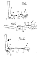
- FIGS. 2 and 3 show a first embodiment of a hinge for the stove 1 according to Fig. 1 ,
- the hinge comprises a housing (not shown in the drawing) and a pivot arm 4, which is pivotally mounted on the housing about an axis 5.
- the housing of the hinge is connected to the hearth 1, and the pivot arm 4 is connected to the flap 2.
- the housing is installed lying in the lower region 6 of the cooker 1. It runs in the horizontal direction and perpendicular to the pivot axis of the flap 2.
- the pivot axis of the flap 2 coincides with the axis 5 of the hinge.
- the swivel arm 4 may be formed as a plug-in part, which is inserted into a corresponding recess in the flap 2 and preferably latched there.
- the linear drive 8 comprises a cylinder 9, in which a drive rod 10 is guided longitudinally displaceable.
- the drive rod 10 is electromechanically actuated. It is in the installed state of the hinge in a horizontal direction and perpendicular to axis 5 movable.
- the spring 7 is connected in parallel with the drive rod 10.
- the cylinder 9 facing away from the end of the drive rod 10 is connected to a coupling 11 which is connected to a carriage 12.
- the carriage 12 is slidably guided in the housing of the hinge, in the same direction as the drive rod 10.
- the spring 7 is connected at one end to the housing of the hinge and at the other end to the carriage 12.
- the carriage 12 has a coupling rod 13, at the end facing away from the drive 8 a roller 14 is arranged.
- the roller 14 is in operative connection with a guide track 15 of the swivel arm 4. It rolls on the guideway 15 from.
- the guideway 15 is similar to the corresponding guideway of the hinge of the DE 101 07 138 A1 designed.
- the force can be adjusted, which is required to open the swivel arm 4 and close.
- This force can be applied by the spring 7.
- the force of the spring 7 is changed by the drive 8.
- the biasing force of the spring 7 can be changed. It can be changed in such a way that the force which the roller 14 exerts on the guide track 15 moves the swivel arm 4 in the desired direction.
- the hinge is designed in such a way that the spring 7 carries and balances the weight of the flap 2 over the entire opening area.
- the drive 8 only has to overcome the friction. This makes it possible for the flap Even with a failure of the drive 8, for example, in a power failure, continue to open manually and can be closed.
- the drive of the swing arm 4 via a linear, motorized movement. Hinge side, the translation of the linear movement of the drive 8 takes place in a rotational movement of the pivot arm 4 by the from DE 101 07 138 A1 known curve control.
- the linear movement of the drive rod 10 of the drive 8 is introduced via the carriage 12 in the hinge. If the drive 8 has no self-locking the stove door 2 can be opened manually even in case of power failure. However, it is also possible that in case of failure of the drive 8 by actuation of the flap 2, the clutch 11 disengages to allow opening and closing of the flap 2.
- the carriage 12 is connected to the pivot arm 4 by a lever rod 16.
- the lever rod is pivotally connected to the carriage 12. It has at its end facing away from the carriage 12, the roller 14.
- the clutch 11 is in both the first embodiment after FIGS. 2 and 3 as in the second embodiment 4 and 5 disengaged. As a result, a manual operation of the hinge is also possible when the drive 8 is blocked.
- the spring 7 is not connected in parallel with the drive 8, but connected in series. Accordingly, the drive rod 10 of the linear actuator 8 is not connected to the carriage 12, but with one end of the spring 7. The other end of the spring 7 is connected to the lever rod 16. The other end carries the roller 14, which is in operative connection with the guide track 15.
- the hinge movement can be generated via the bias of the spring 7.
- the closing moment of the flap 2 is influenced by the force of the spring 7. If this spring force is increased, the closing moment of the hinge increases. If this closing torque is higher than the counter-torque generated by the force of gravity of the flap 2, the flap 2 closes. To open the tension of the spring 7 is reduced, whereby the hinge torque is lower than the flap torque and the flap 2 opens.
- the increase and decrease of the tension of the spring 7 is effected by the drive 8.
- the drive method the convenience of manually opening and closing the flap 2 is increased.
- the modified by changing the spring preload hinge torque supports manual movement.
- the hinge comprises a friction roller 17 for driving the pivot arm 4.
- the pivot arm 4 has a mating surface 18 which extends substantially concentrically about the axis 5.
- the friction roller can be driven by a rotary drive.
- the friction roller 17 is driven by a linear drive (not shown in the drawing). In this case, the linear drive can engage a pin eccentrically mounted on the friction roller 17.
- a gear In the embodiment according to 8 and 9 may be used instead of the friction roller 17, a gear.
- the gear In the gear, only a part of the circumference can be provided with teeth.
- the counter surface 18 is formed in this case as a part-Zahlkranz.
- Fig. 10 Fig. a shows a shutter for the door 2 of the oven 1 according to Figs Fig. 1 ,
- the closure can intervene when the flap 2 has been brought from the dashed, horizontal, open position in the drawn, vertical, closed position.
- the closure has a pawl 19, which can be actuated by a drive 20 and which can be latched with a latching element 21.
- the pawl 19 has an outwardly projecting, triangular cross-section. It engages in the correspondingly formed locking element 21, which has an inwardly facing, triangular cross-section.
- the pawl 19 is connected at its opposite end with a spring 22, whose other end is connected to the drive 20.
- the spring 22 is designed as a compression spring.
- the drive 20 is designed as a linear drive.
- the pawl 19 is initially in the retracted position (in Fig. 10 a not shown).
- the linear actuator 20 is actuated in a direction towards the flap 2.
- the pawl 19 locks with the latching element 21.
- the flap 2 is reliably pressed against the seals 23 which are provided on the hearth 1.
- the pawl 19 and the locking element 21 may be formed such that the flap 2 can be opened manually even when the linear drive 20 is blocked. In this case, the pawl 19 is moved against the force of the compression spring 22 to the linear drive 20 out, and the latch is released.
- Fig. 10b shows a modification of the closure according to Fig. 10 a in which the pawl 19 'is designed as a roller and locked with a correspondingly formed locking element 21' at the end of the flap 2.
- the spring is designed as a leaf spring 24.
- the leaf spring 24 is firmly clamped at its end facing away from the flap 2 25.
- the pawl 19 is provided. Between the ends of the leaf spring 24, the linear drive 20 engages.
- the pawl 19 can also according to the embodiment Fig. 11 be disengaged by a manual movement of the flap 2 when the linear actuator 20 is blocked.
- the locking element 21 is provided on the pivot arm 4. Otherwise, the third is right Embodiment after Fig. 12 with the first embodiment according to Fig. 10 a match.
- the latching element 21 is provided on the carriage 12. It is located on the coupling rod 13 of the carriage 12th
- Fig. 14 a and 14b show a fifth embodiment of the closure.
- the catch element 19 is formed on a catch hook 26.
- the catch hook 26 is rotatably mounted on the hearth 1 about an axis 27. It is loaded by a spring 28.
- the spring 28 is designed as a tension spring Stove 1. Its lower end 30 is fixed to the fishing hook 26 at a location spaced from the axis 27.
- a latching element 21 " which is designed as a pin, is provided on the flap 2.
- the latching element 21" is initially located at a distance from and outside the latching pawl 19 ", which is formed as a recess in the catching hook 26.
- the latching element 21 moves in the illustration of Fig. 14 a up. It penetrates into the pawl 19 "and rotates the fishing hook 26 clockwise about the axis 27 until the fishing hook 26, the in Fig. 14b shown, closed position reached. In this position, the lower end 30 of the tension spring 28 is located on the same side of the axle 27 as the detent element 21 ", so that the catching hook 26 is reliably held in the closed position.
- the force of the tension spring 28 can be reduced by a movement of its upper end 29. This can be done by a drive (not shown in the drawing). Instead, the flap 2 can also be opened by hand.
- the locking element 21 "from the in Fig. 14b shown, closed position moves down until the locking element 21 "is released from the pawl 19", as in Fig. 14 a shown.
- the fishing hook 26 is pivoted about the axis 27 in a counterclockwise direction until a projection 31 on the fishing hook 26 abuts against a stop 32 provided on the hearth 1.
- Fig. 15 shows a damper 33 for the hinge.
- Previously known dampers show a temperature-dependent behavior. Increasing the temperature decreases the viscosity of the damper filling, so that the damping effect decreases significantly.
- the damper 33 has two jaws 34, 35 which are arranged at the ends of drive rods 36, 37 of electromechanical linear actuators 38, 39. To improve the damping effect, two clamping jaws 34, 35 are provided. In certain applications, however, a jaw 34, 35 may be sufficient.
- the jaws 34, 35 are on both sides of the carriage 12 or the coupling rod 13.
- the jaws 34, 35, the movement of the hinge and thus the flap 2 depending on the direction of movement, speed and / or rotation angle of the flap 2 preferably proportionally delay so that the respective end position of the door (closed or open) is achieved attenuated. In this case, the extent of damping can be adjusted.
- the stove 1 has on both sides of the opening 3 each have a clamping strip 40 protection.
- the Klemmtikologyn 40 extend in the vertical direction. They interrupt the closing movement when an object, in particular a body part, is located between the flap 2 and the hearth 1.
Landscapes
- Engineering & Computer Science (AREA)
- Chemical & Material Sciences (AREA)
- Combustion & Propulsion (AREA)
- Mechanical Engineering (AREA)
- General Engineering & Computer Science (AREA)
- Cookers (AREA)
- Closing And Opening Devices For Wings, And Checks For Wings (AREA)
- Baking, Grill, Roasting (AREA)
- Electric Ovens (AREA)
Abstract
Description
- Die Erfindung betrifft ein Scharnier, insbesondere für einen Herd, einen Backofen oder ein sonstiges Gerät oder Elektrogerät. Die Erfindung betrifft ferner einen Herd oder dergleichen, insbesondere einen Backofen, ein sonstiges Gerät oder Elektrogerät.
- Ein Scharnier der eingangs angegebenen Art ist aus der
DE 101 07 138 A1 bekannt. Auf diese Veröffentlichung wird ausdrücklich Bezug genommen. - Aufgabe der Erfindung ist es, ein verbessertes Scharnier, insbesondere für einen Herd, vorzuschlagen.
- Erfindungsgemäß wird diese Aufgabe durch die Merkmale des Anspruchs 1 gelöst. Das Scharnier umfasst ein Gehäuse, an dem ein Schwenkarm schwenkbar gelagert ist. Erfindungsgemäß ist an dem Gehäuse ein Antrieb zum Betätigen des Schwenkarms vorgesehen. Der Antrieb kann als Linearantrieb oder als Rotationsantrieb ausgestaltet sein. Vorzugsweise ist der Antrieb in dem Gehäuse vorgesehen. Er kann an das Gehäuse angekoppelt sein. Der Antrieb ist vorzugsweise ein elektromechanischer Antrieb, insbesondere ein elektromechanischer Linearantrieb oder ein elektromechanischer Rotationsantrieb. Vorteilhaft ist es, wenn der Antrieb keine Selbsthemmung aufweist. Hierdurch wird es ermöglicht, das Scharnier auch von Hand zu betätigen.
- Durch den Antrieb kann die Bedienung des Scharniers vereinfacht werden. Ferner kann der Komfort gegenüber gebräuchlichen Scharnieren verbessert werden. Es ist ferner möglich, zusätzliche Schutzfunktionen für das Gerät und/oder den Bediener zu realisieren.
- Vorteilhafte Weiterbildungen sind in den Unteransprüchen beschrieben.
- Vorteilhaft ist es, wenn an dem Gehäuse ein Wagen längsverschieblich gelagert ist, der von dem Antrieb, insbesondere einem Linearantrieb, betätigbar ist und der mit dem Schwenkarm verbunden ist. Der Wagen ist mit dem Schwenkarm vorzugsweise gelenkig verbunden. Er ist vorzugsweise in dem Gehäuse längsverschieblich gelagert.
- Nach einer weiteren vorteilhaften Weiterbildung ist der Antrieb, insbesondere ein Linearantrieb, mit dem Wagen durch eine Kupplung verbunden. Die Kupplung ist vorzugsweise ausrastbar. Hierdurch kann gewährleistet werden, dass das Scharnier auch manuell betätigt, insbesondere geöffnet werden kann.
- Nach einer weiteren vorteilhaften Weiterbildung ist der Antrieb, insbesondere ein Linearantrieb, oder der Wagen mit dem Schwenkarm durch eine Hebelstange verbunden. Die Hebelstange ist mit dem Antrieb oder Linearantrieb und/oder dem Wagen und/oder dem Schwenkarm vorzugsweise gelenkig verbunden.
- Vorteilhaft ist es, wenn an dem Gehäuse des Scharniers eine Feder gelagert ist, die mit dem Schwenkarm in Wirkverbindung steht. Die Feder ist vorzugsweise in dem Gehäuse gelagert. Sie ist vorzugsweise als Zugfeder ausgebildet.
- Die Feder kann mit dem Antrieb, insbesondere einem Linearantrieb, parallelgeschaltet sein. Sie kann allerdings mit dem Antrieb, insbesondere einem Linearantrieb, auch in Serie geschaltet sein.
- Das Scharnier kann eine Reibrolle oder ein Zahnrad zum Antrieb des Schwenkarms umfassen. Dabei kann die Verzahnung des Zahnrads nur über einen Teil des Umfangs des Zahnrads ausgebildet sein. Die Reibrolle oder das Zahnrad können durch einen Linearantrieb oder durch einen Rotationsantrieb antreibbar sein. Sie können federbelastet sein.
- Nach einer weiteren vorteilhaften Weiterbildung umfasst das Scharnier eine Sperrklinke, die durch einen Antrieb betätigbar und mit einem Rastelement verrastbar ist. Die Sperrklinke und das Rastelement bilden einen Verschluss. Um ein gutes Backergebnis zu erreichen und Energieverluste zu vermeiden ist es wichtig, dass die Backofentüre im geschlossenen Zustand gut abdichtet. Dies kann dadurch erreicht werden, dass das oder die Scharniere in der geschlossenen Stellung ein Drehmoment erzeugen, das größer ist als das Drehmoment, das zum Schließen der Backofentüre eigentlich benötigt wird. Dadurch wird die Backofentüre gegen die Dichtungen an der Öffnung des Backofens gedrückt, wodurch sie zuverlässig abdichtet. Es kann allerdings vorteilhaft sein, eine Erhöhung der Schließkraft der Türe durch einen Verschluss zu erreichen. Hierdurch können die Maximalkräfte des Scharnierantriebs verringert werden.
- Vorzugsweise ist die Sperrklinke elektromechanisch betätigbar. Sie kann federbelastet sein. Die Federbelastung kann als Druckfeder oder Blattfeder oder sonstige Feder ausgestaltet sein.
- Vorteilhaft ist es, wenn das Rastelement an dem Schwenkarm, an dem Wagen oder an der Hebelstange vorgesehen ist.
- Das Rastelement kann an einem Fanghaken ausgebildet sein. Vorzugsweise ist der Fanghaken federbelastet, insbesondere durch eine Zugfeder. Die Sperrklinke kann als Stift ausgebildet sein.
- Nach einer weiteren vorteilhaften Weiterbildung ist der Fanghaken durch einen Antrieb betätigbar, vorzugsweise durch einen elektromechanischen Antrieb.
- Das Scharnier kann einen Dämpfer zum Dämpfen der Bewegung des Schwenkarms umfassen. Vorteilhaft ist es, wenn der Dämpfer eine oder mehrere betätigbare Klemmbacken aufweist, wobei die Klemmbacken vorzugsweise elektromechanisch betätigbar sind. Die Klemmbacken können in Wirkverbindung mit dem Schwenkarm, dem Wagen und/oder der Hebelstange stehen.
- Bei einem Herd oder dergleichen, insbesondere einem Backofen, einem Gerät oder einem Elektrogerät mit einer Klappe wird die Aufgabe der Erfindung durch die Merkmale des Anspruchs 14 gelöst. Der Herd oder dergleichen umfasst eines oder mehrere, vorzugsweise zwei erfindungsgemäße Scharniere.
- Vorteilhaft ist es, wenn das Gehäuse des oder der Scharniere in dem Herd oder dergleichen angeordnet ist. Insbesondere können das oder die Gehäuse liegend in den Backofen eingesetzt werden. Hierdurch kann der Vorteil erreicht werden, dass für den Antrieb mehr Platz vorhanden ist und dass das Scharnier durch die tiefe Einbaulage nicht den hohen Temperaturen ausgesetzt wird, die im Falle eines Einbaus in die Klappe vorhanden sind.
- Es kann allerdings auch vorteilhaft sein, wenn der Herd oder dergleichen ein erfindungsgemäßes Scharnier aufweist und wenn das oder die anderen Scharniere nicht durch einen Antrieb betätigbar sind. Die nicht durch einen Antrieb betätigbaren, "neutralen" Scharniere können eine Feder zum Gewichtsausgleich der Klappe aufweisen. Dadurch, dass nur ein erfindungsgemäßes Scharnier verwendet wird, kann eine aufwendige Synchronisation mehrere Scharnierantriebe entfallen.
- Besonders vorteilhaft kann es sein wenn der Herd oder dergleichen zwei Scharniere aufweist, nämlich ein erfindungsgemäßes Scharnier und ein Scharnier, das nicht durch einen Antrieb betätigbar ist, wobei dieses nicht durch einen Antrieb betätigbare Scharnier vorzugsweise eine Feder aufweist. Die Feder dient vorzugsweise zum Gewichtsausgleich der Klappe. Die Scharniere befinden sich vorzugsweise auf verschiedenen Seiten der Öffnung des Herdes.
- Nach einer weiteren vorteilhaften Weiterbildung umfasst der Herd oder dergleichen einen Verschluss mit einer Sperrklinke, die durch einen Antrieb betätigbar und mit einem Rastelement verrastbar ist. Der Verschluss kann dieselben Merkmale aufweisen, die bereits hinsichtlich des Scharniers beschrieben worden sind. Die Sperrklinke kann herdseitig angeordnet sein. Es ist allerdings auch möglich, dass die Sperrklinke klappenseitig angeordnet ist. Das Rastelement ist an dem jeweils anderen Bauteil angeordnet. Bei dem Antrieb handelt es sich vorzugsweise um einen elektromechanischen Antrieb. Die Sperrklinke kann federbelastet sein, insbesondere durch eine Druckfeder, Blattfeder oder sonstige Feder. Das Rastelement kann als Fanghaken ausgebildet sein, vorzugsweise als federbelasteter Fanghaken, wobei die Feder vorzugsweise als Zugfeder ausgebildet ist. Die Sperrklinke kann als Stift ausgebildet sein. Der Fanghaken kann durch einen vorzugsweise elektromechanischen Antrieb betätigbar sein.
- Nach einer weiteren vorteilhaften Weiterbildung sind an dem Herd und/oder and der Klappe eine oder mehrere Klemmschutzleisten vorgesehen. Die eine oder mehreren Klemmschutzleisten können seitlich an der Öffnung für die Klappe vorgesehen sein. Bei einer motorischen Schließbewegung der Herdklappe besteht die Gefahr des Einklemmens der Finger zwischen Herdklappe und Backrohr. Diese Gefahr ist in der Nähe des Klappendrehpunktes am größten, da dort die Schließkräfte am größten sind. Durch die Klemmschutzleisten kann die Schließbewegung der Klappe unterbrochen werden, falls sich ein Finger oder ein Gegenstand zwischen der Klappe und dem Herd befindet. In bestimmten Fällen kann es vorteilhaft oder ausreichend sein, wenn die Klemmschutzleisten nur im unteren Bereich der Klappe vorhanden sind, also in der Nähe des Klappendrehpunktes. Die Klemmschutzleisten können herdseitig und/oder türseitig angebracht werden. Sie können als Lichtschranken ausgebildet sein.
- Ausführungsbeispiele der Erfindung werden nachstehend an Hand der beigefügten Zeichnungen im Einzelnen erläutert. In der Zeichnung zeigt
- Fig. 1
- einen Herd mit einer Klappe in einer perspektivischen Ansicht,
- Fig. 2
- eine erste Ausführungsform eines Scharniers für den Herd gemäß
Fig. 1 in der geschlossenen Stellung in einer schematischen Seitenansicht, - Fig. 3
- das Scharnier gemäß
Fig. 2 in der geöffneten Stellung, - Fig. 4
- eine zweite Ausführungsform eines Scharniers in der geschlossenen Stellung,
- Fig. 5
- das Scharnier gemäß
Fig. 4 in der geöffneten Stellung, - Fig. 6
- eine dritte Ausführungsform eines Scharniers in der geschlossenen Stellung,
- Fig. 7
- das Scharnier gemäß
Fig. 6 in der geöffneten Stellung, - Fig. 8
- eine vierte Ausführungsform eines Scharniers in der geschlossenen Stellung,
- Fig. 9
- das Scharnier gemäß
Fig. 8 in der geöffneten Stellung, - Fig. 10 a
- einen Verschluss für die Klappe des Herdes gemäß
Fig. 1 in einer schematischen Seitenansicht, - Fig. 10 b
- eine Abwandlung des Verschlusses gemäß
Fig. 10 a, - Fig. 11
- eine zweite Ausführungsform eines Verschlusses für die Klappe des Herdes gemäß
Fig. 1 , - Fig. 12
- eine dritte Ausführungsform eines derartigen Verschlusses,
- Fig. 13
- eine vierte Ausführungsform eines derartigen Verschlusses,
- Fig. 14 a
- eine fünfte Ausführungsform eines Verschlusses für die Klappe des Herdes gemäß
Fig. 1 in der geöffneten Stellung, - Fig. 14 b
- den Verschluss gemäß
Fig. 14 a in der geschlossenen Stellung und - Fig. 15
- einen Dämpfer für die Scharniere gemäß
Fig. 2 und 3 sowie gemäßFig. 4 und 5 . - Die
Fig. 1 zeigt einen Herd 1, an dem eine Klappe 2 um eine horizontale Achse schwenkbar gelagert ist. Die horizontale Schwenkachse befindet sich unterhalb einer Öffnung 3 des Backofens. -
Fig. 2 und 3 zeigen eine erste Ausführungsform eines Scharniers für den Herd 1 gemäßFig. 1 . Das Scharnier umfasst ein Gehäuse (in der Zeichnung nicht dargestellt) und einen Schwenkarm 4, der an dem Gehäuse um eine Achse 5 schwenkbar gelagert ist. Das Gehäuse des Scharniers ist mit dem Herd 1 verbunden, und der Schwenkarm 4 ist mit der Klappe 2 verbunden. Das Gehäuse ist im unteren Bereich 6 des Herdes 1 liegend eingebaut. Es verläuft in horizontaler Richtung und senkrecht zur Schwenkachse der Klappe 2. Die Schwenkachse der Klappe 2 stimmt mit der Achse 5 des Scharniers überein. Der Schwenkarm 4 kann als Steckteil ausgebildet sein, der in eine entsprechende Vertiefung in der Klappe 2 eingesteckt und vorzugsweise dort verrastet wird. - In dem Gehäuse des Scharniers sind eine Feder 7, die als Zugfeder ausgebildet ist, und ein Antrieb 8, der als Linearantrieb ausgeführt ist, vorgesehen. Der Linearantrieb 8 umfasst einen Zylinder 9, in dem eine Antriebsstange 10 längsverschieblich geführt ist. Die Antriebsstange 10 ist elektromechanisch betätigbar. Sie ist im eingebauten Zustand des Scharniers in waagerechter Richtung und senkrecht zu Achse 5 beweglich. Die Feder 7 ist mit der Antriebsstange 10 parallelgeschaltet.
- Das dem Zylinder 9 abgewandte Ende der Antriebsstange 10 ist mit einer Kupplung 11 verbunden, die mit einem Wagen 12 verbunden ist. Der Wagen 12 ist in dem Gehäuse des Scharniers längsverschieblich geführt, und zwar in derselben Richtung wie die Antriebsstange 10. Die Feder 7 ist an einem Ende mit dem Gehäuse des Scharniers und am anderen Ende mit dem Wagen 12 verbunden.
- Der Wagen 12 weist eine Koppelstange 13 auf, an deren dem Antrieb 8 abgewandten Ende ein Rolle 14 angeordnet ist. Die Rolle 14 steht mit einer Führungsbahn 15 des Schwenkarms 4 in Wirkverbindung. Sie rollt auf der Führungsbahn 15 ab.
- Die Führungsbahn 15 ist ähnlich wie die entsprechende Führungsbahn des Scharniers der
DE 101 07 138 A1 ausgestaltet. Durch die jeweilige Neigung der Führungsbahn 15 gegenüber einem Kreis um die Achse 5 kann die Kraft eingestellt werden, die erforderlich ist, um den Schwenkarm 4 zu öffnen und zu schließen. Diese Kraft kann durch die Feder 7 aufgebracht werden. Dabei ist die Kraft der Feder 7 durch den Antrieb 8 veränderbar. Durch eine Bewegung der Antriebsstange 10 kann die Vorspannungskraft der Feder 7 verändert werden. Sie kann in der Weise verändert werden, dass die Kraft, die die Rolle 14 auf die Führungsbahn 15 ausübt, den Schwenkarm 4 in der gewünschten Richtung bewegt. - Wenn die Antriebsstange 10 in den Zylinder 9 hineinbewegt wird, wie in
Fig. 2 gezeigt, wird der Schwenkarm 4 im Uhrzeigersinn um die Achse 5 verschwenkt. Dadurch wird das Scharnier geschlossen. - Wenn die Antriebsstange 10 aus dem Zylinder 9 herausbewegt wird, wie in
Fig. 3 gezeigt, wird der Schwenkarm 4 entgegen dem Uhrzeigersinn um die Achse 5 verschwenkt. Dadurch wird das Scharnier geöffnet. - Das Scharnier ist in der Weise ausgestaltet, dass die Feder 7 das Gewicht der Klappe 2 über den gesamten Öffnungsbereich trägt und ausgleicht. Der Antrieb 8 muss lediglich die Reibung überwinden. Hierdurch ist es möglich, dass die Klappe auch bei einem Ausfall des Antriebs 8, beispielsweise bei einem Stromausfall, weiterhin manuell geöffnet und geschlossen werden kann. Der Antrieb des Schwenkarms 4 erfolgt über eine lineare, motorische Bewegung. Scharnierseitig erfolgt die Übersetzung der linearen Bewegung des Antriebs 8 in eine Drehbewegung des Schwenkarms 4 durch die aus der
DE 101 07 138 A1 bekannte Kurvensteuerung. Die lineare Bewegung der Antriebsstange 10 des Antriebs 8 wird über den Wagen 12 in das Scharnier eingeleitet. Wenn der Antrieb 8 keine Selbsthemmung aufweist kann die Herdklappe 2 auch bei Stromausfall manuell geöffnet werden. Es ist allerdings auch möglich, dass bei einem Ausfall des Antriebs 8 durch eine Betätigung der Klappe 2 die Kupplung 11 ausrastet, um ein Öffnen und Schließen der Klappe 2 zu ermöglichen. -
Fig. 4 und 5 zeigen eine zweite Ausführungsform des Scharniers, bei der übereinstimmende Teile mit denselben Bezugszeichen versehen sind und nicht erneut beschrieben werden. Bei dieser Ausführungsform ist der Wagen 12 mit dem Schwenkarm 4 durch eine Hebelstange 16 verbunden. Die Hebelstange ist mit dem Wagen 12 gelenkig verbunden. Sie weist an ihrem dem Wagen 12 abgewandten Ende die Rolle 14 auf. - Die Kupplung 11 ist sowohl bei der ersten Ausführungsform nach
Fig. 2 und 3 wie auch bei der zweiten Ausführungsform nachFig. 4 und 5 ausrastbar. Hierdurch ist eine manuelle Bedienung des Scharniers auch dann möglich, wenn der Antrieb 8 blockiert ist. - Bei der dritten Ausführungsform nach
Fig. 6 und7 ist die Feder 7 nicht mit dem Antrieb 8 parallelgeschaltet, sondern in Serie geschaltet. Dementsprechend ist die Antriebsstange 10 des Linearantriebs 8 nicht mit dem Wagen 12 verbunden, sondern mit einem Ende der Feder 7. Das andere Ende der Feder 7 ist mit der Hebelstange 16 verbunden. Deren anderes Ende trägt die Rolle 14, die mit der Führungsbahn 15 in Wirkverbindung steht. - Bei der Ausführungsform nach
Fig. 6 und7 kann die Scharnierbewegung über die Vorspannung der Feder 7 generiert werden. Das Schließmoment der Klappe 2 wird von der Kraft der Feder 7 beeinflusst. Wird diese Federkraft erhöht, steigt das Schließmoment des Scharniers. Ist dieses Schließmoment höher als das durch die Schwerkraft der Klappe 2 erzeugte Gegenmoment, schließt die Klappe 2. Zum Öffnen wird die Spannung der Feder 7 reduziert, wodurch das Scharniermoment geringer als das Klappenmoment wird und die Klappe 2 sich öffnet. Die Erhöhung und Verminderung der Spannung der Feder 7 erfolgt durch den Antrieb 8. Durch diese Antriebsmethode wird der Komfort beim manuellen Öffnen und Schließen der Klappe 2 erhöht. Das durch die Änderung der Federvorspannung modifizierte Scharniermoment unterstützt die manuelle Bewegung. - Bei der vierten Ausführungsform nach
Fig. 8 und 9 umfasst das Scharnier eine Reibrolle 17 zum Antrieb des Schwenkarms 4. Der Schwenkarm 4 weist eine Gegenfläche 18 auf, die im Wesentlichen konzentrisch um die Achse 5 verläuft. Die Reibrolle kann durch einen Rotationsantrieb angetrieben werden. Es ist allerdings auch möglich, dass die Reibrolle 17 durch einen Linearantrieb angetrieben wird (in der Zeichnung nicht dargestellt). In diesem Fall kann der Linearantrieb an einem Zapfen angreifen, der exzentrisch an der Reibrolle 17 angebracht ist. - Bei der Ausführungsform nach
Fig. 8 und 9 kann an Stelle der Reibrolle 17 ein Zahnrad verwendet werden. Bei dem Zahnrad kann nur ein Teil des Umfangs mit Zähnen versehen sein. Die Gegenfläche 18 ist in diesem Fall als Teil-Zahlkranz ausgebildet. -
Fig. 10 a zeigt einen Verschluss für die Klappe 2 des Herdes 1 gemäßFig. 1 . Der Verschluss kann eingreifen, wenn die Klappe 2 aus der gestrichelt gezeichneten, waagerechten, geöffneten Stellung in die durchgezogen gezeichnete, vertikale, geschlossene Stellung gebracht worden ist. Der Verschluss weist eine Sperrklinke 19 auf, die durch einen Antrieb 20 betätigbar ist und die mit einem Rastelement 21 verrastbar ist. Die Sperrklinke 19 weist einen nach außen vorstehenden, dreieckformigen Querschnitt auf. Sie greift in das entsprechend ausgebildete Rastelement 21 ein, das einen nach innen weisenden, dreieckförmigen Querschnitt aufweist. Die Sperrklinke 19 ist an ihrem gegenüberliegenden Ende mit einer Feder 22 verbunden, deren anderes Ende mit dem Antrieb 20 verbunden ist. Die Feder 22 ist als Druckfeder ausgebildet. Der Antrieb 20 ist als Linearantrieb ausgebildet. - Im Betrieb befindet sich die Sperrklinke 19 zunächst in der eingezogenen Stellung (in
Fig. 10 a nicht dargestellt). Wenn die Klappe 2 die geschlossene Stellung erreicht hat, wird der Linearantrieb 20 in einer Richtung zur Klappe 2 hin betätigt. Dadurch verrastet die Sperrklinke 19 mit dem Rastelement 21. In der verrasteten Stellung wird die Klappe 2 zuverlässig gegen die Dichtungen 23 gedrückt, die an dem Herd 1 vorgesehen sind. - Die Sperrklinke 19 und das Rastelement 21 können derart ausgebildet sein, dass die Klappe 2 auch dann manuell geöffnet werden kann, wenn der Linearantrieb 20 blockiert ist. In diesem Fall wird die Sperrklinke 19 entgegen der Kraft der Druckfeder 22 zum Linearantrieb 20 hin bewegt, und die Verrastung wird freigegeben.
-
Fig. 10 b zeigt eine Abwandlung des Verschlusses gemäßFig. 10 a , bei der die Sperrklinke 19' als Rolle ausgestaltet ist und mit einem entsprechend ausgebildeten Rastelement 21' am Ende der Klappe 2 verrastet. - Bei der in
Fig. 11 gezeigten, zweiten Ausführungsform des Verschlusses werden übereinstimmende Teile mit denselben Bezugszeichen versehen und nicht erneut beschrieben. Hier ist die Feder als Blattfeder 24 ausgebildet. Die Blattfeder 24 ist an ihrem der Klappe 2 abgewandtem Ende 25 fest eingespannt. An ihrem anderen Ende ist die Sperrklinke 19 vorgesehen. Zwischen den Enden der Blattfeder 24 greift der Linearantrieb 20 an. Die Sperrklinke 19 kann auch bei der Ausführungsform nachFig. 11 durch eine manuelle Bewegung der Klappe 2 ausgerastet werden, wenn der Linearantrieb 20 blockiert ist. - Bei der dritten Ausführungsform des Verschlusses, die in
Fig. 12 gezeigt ist, ist das Rastelement 21 an dem Schwenkarm 4 vorgesehen. Ansonsten stimmt die dritte Ausführungsform nachFig. 12 mit der ersten Ausführungsform nachFig. 10 a überein. - Bei der vierten Ausführungsform nach
Fig. 13 ist das Rastelement 21 an dem Wagen 12 vorgesehen. Es befindet sich an der Koppelstange 13 des Wagens 12. -
Fig. 14 a und 14 b zeigen eine fünfte Ausführungsform des Verschlusses. Hier ist das Rastelement 19" an einem Fanghaken 26 ausgebildet. Der Fanghaken 26 ist um eine Achse 27 an dem Herd 1 drehbar gelagert. Er ist durch eine Feder 28 belastet. Die Feder 28 ist als Zugfeder ausgebildet. Ihr oberes Ende 29 ist an dem Herd 1 befestigt. Ihr unteres Ende 30 ist an dem Fanghaken 26 an einer von der Achse 27 beabstandeten Stelle befestigt. - Wenn sich die Klappe 2 in der geöffneten Stellung befindet, befindet sich auch der Verschluss in der in
Fig. 14 a gezeigten, geöffneten Stellung. An der Klappe 2 ist ein Rastelement 21" vorgesehen, das als Stift ausgebildet ist. Das Rastelement 21" befindet sich zunächst im Abstand von und außerhalb der Sperrklinke 19", die als Vertiefung in dem Fanghaken 26 ausgebildet ist. - Wenn die Klappe 2 geschlossen wird, bewegt sich das Rastelement 21" in der Darstellung der
Fig. 14 a nach oben. Es dringt in die Sperrklinke 19" ein und verdreht den Fanghaken 26 im Uhrzeigersinn um die Achse 27, bis der Fanghaken 26 die inFig. 14 b gezeigte, geschlossene Stellung erreicht. In dieser Stellung befindet sich das untere Ende 30 der Zugfeder 28 auf derselben Seite der Achse 27 wie das Rastelement 21". Auf diese Weise wird der Fanghaken 26 zuverlässig in der geschlossenen Stellung gehalten. - Zum Öffnen des Verschlusses kann die Kraft der Zugfeder 28 durch eine Bewegung ihres oberen Endes 29 vermindert werden. Dies kann durch einen Antrieb erfolgen (in der Zeichnung nicht dargestellt). Stattdessen kann die Klappe 2 auch von Hand geöffnet werden. In beiden Fällen wird das Rastelement 21" aus der in
Fig. 14 b gezeigten, geschlossenen Stellung nach unten bewegt, bis das Rastelement 21" aus der Sperrklinke 19" freigegeben wird, wie inFig. 14 a gezeigt. Im Zuge dieser Bewegung wird der Fanghaken 26 um die Achse 27 in einer Richtung entgegen dem Uhrzeigersinn verschwenkt, bis ein Vorsprung 31 an dem Fanghaken 26 an einem Anschlag 32, der an dem Herd 1 vorgesehen ist, anliegt. - Bei der Ausführungsform nach
Fig. 14 a und 14 b fährt das als Stift ausgebildete Rastelement 21" beim Schließen in die als Vertiefung ausgebildete Sperrklinke 19" des scheibenförmigen Fanghakens 26 und verdreht diesen im Uhrzeigersinn, sodass die darin eingehängte Feder 28 über ihren Totpunkt läuft. Der dadurch entstehende Hebelarm der Federkraft hält die Klappe geschlossen. Zum Öffnen muss entweder manuell eine bestimmte Kraft aufgebracht werden, oder mittels eines Antriebs wird der scheibenförmige Fanghaken 26 geöffnet. - Bei dieser Ausführungsform ist es möglich, durch einen mechatronischen Impuls beim Beginn des Öffnungsvorgangs die Federeinhängung über den Totpunkt zu versetzen und damit das Drehmoment umzukehren, sodass der Fanghaken 26 die Öffnung unterstützt und das stiftförmige Rastelement 21" und damit die Tür aufdrückt. Dies ist besonders vorteilhaft bei einer Klappe 2 ohne Griff, bei der die Öffnung durch ein Betätigungselement oder durch eine Sprachsteuerung gestartet werden kann.
-
Fig. 15 zeigt einen Dämpfer 33 für das Scharnier. Vorbekannte Dämpfer zeigen ein temperaturabhängiges Verhalten. Durch eine Erhöhung der Temperatur sinkt die Viskosität der Dämpferfüllung, sodass die Dämpfwirkung deutlich nachlässt. Um dies zu vermeiden weist der Dämpfer 33 zwei Klemmbacken 34, 35 auf, die an den Enden von Antriebsstangen 36, 37 von elektromechanischen Linearantrieben 38, 39 angeordnet sind. Zur Verbesserung der Dämpfungswirkung sind zwei Klemmbacken 34, 35 vorgesehen. In bestimmten Anwendungsfällen kann allerdings eine Klemmbacke 34, 35 ausreichend sein. Die Klemmbacken 34, 35 liegen zu beiden Seiten des Wagens 12 oder der Koppelstange 13. Die Klemmbacken 34, 35 können die Bewegung des Scharniers und damit der Klappe 2 in Abhängigkeit von Bewegungsrichtung, Geschwindigkeit und/oder Drehwinkel der Klappe 2 vorzugsweise proportional derart verzögern, dass die jeweilige Endstellung der Tür (geschlossen oder geöffnet) abgedämpft erreicht wird. Dabei kann das Ausmaß der Dämpfung eingestellt werden. - Der Herd 1 weist an beiden Seiten der Öffnung 3 jeweils eine Klemmschutzleiste 40 auf. Die Klemmschutzleisten 40 verlaufen in vertikaler Richtung. Sie unterbrechen die Schließbewegung, wenn sich ein Gegenstand, insbesondere ein Körperteil, zwischen der Klappe 2 und dem Herd 1 befindet.
Claims (19)
- Scharnier, insbesondere für einen Herd (1), mit einem Gehäuse, an dem ein Schwenkarm (4) schwenkbar (5) gelagert ist,
dadurch gekennzeichnet,
daß an dem Gehäuse ein Antrieb (8) zum Betätigen des Schwenkarms (4) vorgesehen ist. - Scharnier nach Anspruch 1, dadurch gekennzeichnet, daß an dem Gehäuse ein Wagen (12) längsverschieblich gelagert ist, der von dem Antrieb (8) betätigbar ist und der mit dem Schwenkarm (4) verbunden ist.
- Scharnier nach Anspruch 2, dadurch gekennzeichnet, daß der Antrieb (8) mit dem Wagen (12) durch eine Kupplung (11) verbunden ist.
- Scharnier nach einem der vorhergehenden Ansprüche, dadurch gekennzeichnet, daß der Antrieb (8) oder der Wagen (12) mit dem Schwenkarm (4) durch eine Hebelstange (16) verbunden ist.
- Scharnier nach einem der vorhergehenden Ansprüche, dadurch gekennzeichnet, daß an dem Gehäuse eine Feder (7) gelagert ist, die mit dem Schwenkarm (4) in Wirkverbindung steht.
- Scharnier nach Anspruch 5, dadurch gekennzeichnet, daß die Feder (7) mit dem Antrieb (8) parallelgeschaltet oder in Serie geschaltet ist.
- Scharnier nach einem der vorhergehenden Ansprüche, gekennzeichnet durch eine Reibrolle (17) oder ein Zahnrad zum Antrieb des Schwenkarms (4).
- Scharnier nach einem der vorhergehenden Ansprüche, gekennzeichnet durch eine Sperrklinke (19, 19', 19"), die durch einen Antrieb (20) betätigbar und mit einem Rastelement (21, 21', 21 ") verrastbar ist.
- Scharnier nach Anspruch 8, dadurch gekennzeichnet, daß die Sperrklinke (19, 19', 19") federbelastet (22, 24, 28) ist.
- Scharnier nach Anspruch 8 oder 9, dadurch gekennzeichnet, daß das Rastelement (21) an dem Schwenkarm (4), an dem Wagen (12) oder an der Hebelstange (13) vorgesehen ist.
- Scharnier nach einem der Ansprüche 8 bis 10, dadurch gekennzeichnet, daß das Rastelement (21") an einem Fanghaken (26) ausgebildet ist, der vorzugsweise durch einen Antrieb betätigbar ist.
- Scharnier nach einem der vorhergehenden Ansprüche, gekennzeichnet durch einen Dämpfer (33) zum Dämpfen der Bewegung des Schwenkarms (4).
- Scharnier nach Anspruch 12, dadurch gekennzeichnet, dass der Dämpfer (33) betätigbare Klemmbacken (34, 35) aufweist.
- Herd oder dergleichen mit einer Klappe (2),
gekennzeichnet durch
eines oder mehrere Scharniere nach einem der Ansprüche 1 bis 13. - Herd oder dergleichen nach Anspruch 14, dadurch gekennzeichnet, dass das Gehäuse des oder der Scharniere in dem Herd (1) oder dergleichen angeordnet ist.
- Herd oder dergleichen nach Anspruch 14 oder 15, gekennzeichnet durch ein Scharnier nach einem der Ansprüche 1 bis 13 und eines oder mehrere Scharniere, die nicht durch einen Antrieb betätigbar sind.
- Herd oder dergleichen nach einem der Ansprüche 14 bis 16, gekennzeichnet durch ein Scharnier nach einem der Ansprüche 1 bis 13 und ein Scharnier, das nicht durch einen Antrieb betätigbar ist und das vorzugsweise eine Feder aufweist.
- Herd oder dergleichen nach einem der Ansprüche 14 bis 17, gekennzeichnet durch einen Verschluß mit einer Sperrklinke (19, 19', 19"), die durch einen Antrieb (20) betätigbar und mit einem Rastelement (21, 21', 21 ") verrastbar ist.
- Herd oder dergleichen nach einem der Ansprüche 14 bis 18, dadurch gekennzeichnet, daß an dem Herd (1) und/oder an der Klappe (2) eine oder mehrere Klemmschutzleisten vorgesehen sind.
Applications Claiming Priority (1)
| Application Number | Priority Date | Filing Date | Title |
|---|---|---|---|
| DE102013001402.6A DE102013001402B4 (de) | 2013-01-28 | 2013-01-28 | Scharnier für einen Herd sowie Herd |
Publications (3)
| Publication Number | Publication Date |
|---|---|
| EP2759669A2 true EP2759669A2 (de) | 2014-07-30 |
| EP2759669A3 EP2759669A3 (de) | 2015-12-30 |
| EP2759669B1 EP2759669B1 (de) | 2021-09-29 |
Family
ID=49989476
Family Applications (1)
| Application Number | Title | Priority Date | Filing Date |
|---|---|---|---|
| EP14000166.0A Active EP2759669B1 (de) | 2013-01-28 | 2014-01-16 | Scharnier für einen herd |
Country Status (3)
| Country | Link |
|---|---|
| EP (1) | EP2759669B1 (de) |
| DE (1) | DE102013001402B4 (de) |
| ES (1) | ES2900403T3 (de) |
Cited By (10)
| Publication number | Priority date | Publication date | Assignee | Title |
|---|---|---|---|---|
| DE102015000407B3 (de) * | 2015-01-13 | 2016-04-21 | Apparatebau Gronbach GmbH | Scharnier sowie Herd mit einem solchen Scharnier |
| EP3199735A1 (de) | 2016-01-29 | 2017-08-02 | Apparatebau Gronbach Srl | Dämpfermodul für ein scharnier insbesondere für ein haushaltsgeräts, sowie scharnier, insbesondere für ein haushaltsgerät |
| EP3508676A1 (de) | 2018-01-03 | 2019-07-10 | Apparatebau Gronbach Srl | Scharnier für ein haushaltsgerät |
| CN110685524A (zh) * | 2019-11-01 | 2020-01-14 | 东莞市鼎太电器有限公司 | 手自一体电动烤箱门铰链 |
| CN111173389A (zh) * | 2018-11-09 | 2020-05-19 | 广东美的厨房电器制造有限公司 | 烹饪器具的门体铰链和具有其的烹饪器具 |
| CN112196393A (zh) * | 2020-08-20 | 2021-01-08 | 浙江美多电器有限公司 | 可延长电机寿命的厨房电器箱门驱动装置 |
| WO2021150185A1 (en) * | 2020-01-21 | 2021-07-29 | Atasan Metal Sanayi Ticaret Anonim Sirketi | Hinge assembly fixing system |
| CN117211627A (zh) * | 2023-09-08 | 2023-12-12 | 宁波方太厨具有限公司 | 一种用于家用电器的门铰链及家用电器 |
| EP4467758A1 (de) | 2023-05-24 | 2024-11-27 | GRONBACH G.m.b.H | Scharnier für ein haushaltsgerät sowie verfahren zum betreiben eines solchen scharniers |
| DE102024113208B3 (de) * | 2024-05-13 | 2025-07-24 | Miele & Cie. Kg | Haushaltsgerät mit beweglichem Verschlusselement |
Families Citing this family (3)
| Publication number | Priority date | Publication date | Assignee | Title |
|---|---|---|---|---|
| ES2983548T3 (es) * | 2020-06-01 | 2024-10-23 | Soluciones Conceptuales E Innovacion S L | Contenedor de residuos urbanos con un dispositivo de apertura y cierre automático de su tapa |
| BE1031605B1 (de) * | 2023-05-10 | 2024-12-11 | Miele & Cie | Haushaltsgerät mit motorisch beweglichem Verschlusselement |
| DE102024112751B3 (de) * | 2024-05-07 | 2025-07-03 | Miele & Cie. Kg | Haushaltsgerät mit motorisch beweglichem Verschlusselement |
Citations (3)
| Publication number | Priority date | Publication date | Assignee | Title |
|---|---|---|---|---|
| DE10107138A1 (de) * | 2001-02-15 | 2002-08-29 | Gronbach Forschungs Und Entwic | Scharnier für eine Herdklappe |
| DE102005002822A1 (de) * | 2005-01-20 | 2006-08-03 | Electrolux Home Products Corporation N.V. | Türscharnier für ein Haushaltsgerät |
| WO2014111827A1 (en) * | 2013-01-15 | 2014-07-24 | Faringosi Hinges S.R.L. | Hinge |
Family Cites Families (7)
| Publication number | Priority date | Publication date | Assignee | Title |
|---|---|---|---|---|
| DE10228141A1 (de) * | 2002-06-24 | 2004-01-22 | BSH Bosch und Siemens Hausgeräte GmbH | Gargerät |
| DE10301373A1 (de) * | 2003-01-16 | 2004-07-29 | Grundig Aktiengesellschaft | Scharnier |
| DE10362318B4 (de) * | 2003-12-22 | 2011-02-03 | Electrolux Home Products Corporation N.V. | Türscharnier für eine Tür eines Haushaltsgeräts sowie Haushaltsgerät mit wenigstens einem Türscharnier |
| DE102004062235A1 (de) * | 2004-12-23 | 2006-07-13 | BSH Bosch und Siemens Hausgeräte GmbH | Einbauhaushaltsgerät |
| US7755004B2 (en) * | 2006-04-14 | 2010-07-13 | Mansfield Assemblies Co. | Motorized hinge system for oven door |
| AT508072B1 (de) * | 2009-03-19 | 2016-01-15 | Blum Gmbh Julius | Anordnung, umfassend ein Möbelscharnier und ein Antriebssystem |
| DE102011010439A1 (de) * | 2010-02-09 | 2011-08-11 | Marquardt Mechatronik GmbH, 78604 | Verschluss für ein Hausgerät |
-
2013
- 2013-01-28 DE DE102013001402.6A patent/DE102013001402B4/de active Active
-
2014
- 2014-01-16 ES ES14000166T patent/ES2900403T3/es active Active
- 2014-01-16 EP EP14000166.0A patent/EP2759669B1/de active Active
Patent Citations (3)
| Publication number | Priority date | Publication date | Assignee | Title |
|---|---|---|---|---|
| DE10107138A1 (de) * | 2001-02-15 | 2002-08-29 | Gronbach Forschungs Und Entwic | Scharnier für eine Herdklappe |
| DE102005002822A1 (de) * | 2005-01-20 | 2006-08-03 | Electrolux Home Products Corporation N.V. | Türscharnier für ein Haushaltsgerät |
| WO2014111827A1 (en) * | 2013-01-15 | 2014-07-24 | Faringosi Hinges S.R.L. | Hinge |
Cited By (17)
| Publication number | Priority date | Publication date | Assignee | Title |
|---|---|---|---|---|
| CN107771237B (zh) * | 2015-01-13 | 2020-01-10 | 格朗巴赫设备制造有限公司 | 灶具用铰链 |
| EP3045639A1 (de) | 2015-01-13 | 2016-07-20 | Apparatebau Gronbach Srl | Scharnier für ein haushaltsgerät sowie verfahren zum betreiben eines solchen scharniers |
| WO2016112939A1 (de) | 2015-01-13 | 2016-07-21 | Apparatebau Gronbach GmbH | Scharnier für einen herd |
| CN107771237A (zh) * | 2015-01-13 | 2018-03-06 | 格朗巴赫设备制造有限公司 | 灶具用铰链 |
| US10301866B2 (en) | 2015-01-13 | 2019-05-28 | Apparatebau Gronbach GmbH | Hinge for household appliance such as oven |
| DE102015000407B3 (de) * | 2015-01-13 | 2016-04-21 | Apparatebau Gronbach GmbH | Scharnier sowie Herd mit einem solchen Scharnier |
| EP3199735A1 (de) | 2016-01-29 | 2017-08-02 | Apparatebau Gronbach Srl | Dämpfermodul für ein scharnier insbesondere für ein haushaltsgeräts, sowie scharnier, insbesondere für ein haushaltsgerät |
| US11480341B2 (en) | 2018-01-03 | 2022-10-25 | Apparatebau Gronbach S.R.L. | Hinge for a household appliance |
| EP3508676A1 (de) | 2018-01-03 | 2019-07-10 | Apparatebau Gronbach Srl | Scharnier für ein haushaltsgerät |
| CN111173389A (zh) * | 2018-11-09 | 2020-05-19 | 广东美的厨房电器制造有限公司 | 烹饪器具的门体铰链和具有其的烹饪器具 |
| CN110685524A (zh) * | 2019-11-01 | 2020-01-14 | 东莞市鼎太电器有限公司 | 手自一体电动烤箱门铰链 |
| WO2021150185A1 (en) * | 2020-01-21 | 2021-07-29 | Atasan Metal Sanayi Ticaret Anonim Sirketi | Hinge assembly fixing system |
| CN112196393A (zh) * | 2020-08-20 | 2021-01-08 | 浙江美多电器有限公司 | 可延长电机寿命的厨房电器箱门驱动装置 |
| EP4467758A1 (de) | 2023-05-24 | 2024-11-27 | GRONBACH G.m.b.H | Scharnier für ein haushaltsgerät sowie verfahren zum betreiben eines solchen scharniers |
| CN117211627A (zh) * | 2023-09-08 | 2023-12-12 | 宁波方太厨具有限公司 | 一种用于家用电器的门铰链及家用电器 |
| DE102024113208B3 (de) * | 2024-05-13 | 2025-07-24 | Miele & Cie. Kg | Haushaltsgerät mit beweglichem Verschlusselement |
| EP4650667A1 (de) | 2024-05-13 | 2025-11-19 | Miele & Cie. KG | Haushaltsgerät mit beweglichem verschlusselement |
Also Published As
| Publication number | Publication date |
|---|---|
| EP2759669A3 (de) | 2015-12-30 |
| DE102013001402B4 (de) | 2016-06-09 |
| EP2759669B1 (de) | 2021-09-29 |
| ES2900403T3 (es) | 2022-03-16 |
| DE102013001402A1 (de) | 2014-07-31 |
Similar Documents
| Publication | Publication Date | Title |
|---|---|---|
| DE102013001402B4 (de) | Scharnier für einen Herd sowie Herd | |
| EP3063354B1 (de) | Scharnier für einen herd | |
| EP1370742B1 (de) | Fenster-oder türaufbau | |
| EP2208846B1 (de) | Vorrichtung für das Steuern der Schließfolge von zweiflügeligen Schwenktüren | |
| DE102005055788B4 (de) | Betätigungseinrichtung für ein bewegliches Bauteil | |
| DE102009036872B4 (de) | Türeinheit | |
| AT506828A2 (de) | Türband für eine verdeckte anordnung zwischen türzarge und gefälztem türflügel | |
| EP2614202B1 (de) | Türeinheit | |
| EP2902577B1 (de) | Vorrichtung für das Steuern der Schließfolge von zweiflügeligen Schwenktüren | |
| DE2923421C2 (de) | Antriebsvorrichtung für einen Tür- bzw. Torflügel | |
| EP1544398B1 (de) | Vorrichtung zur Schliessfolgeregelung für zweiflügelige Drehtüren | |
| EP2732113B1 (de) | Verschluss zum verschliessen einer tür, insbesondere einer gerätetür | |
| EP2450514A1 (de) | Antrieb für einen Flügel einer Tür oder eines Fensters | |
| DE102012220079B3 (de) | Schließfolgeregelung | |
| EP1493892B1 (de) | Verriegelung für den Flügel eines Fensters oder einer Klappe | |
| DE10360039B4 (de) | Vorrichtung zur Schließfolgeregelung für zweiflügelige Drehtüren | |
| EP4223970B1 (de) | Antriebseinheit für ein schiebetor | |
| DE102004038869A1 (de) | Kipp- und/oder Drehvorrichtung für ein Fenster, eine Tür, eine Fenstertür oder dergleichen | |
| EP2647786B1 (de) | Antrieb für einen flügel eines fensters oder dergleichen | |
| DE10147033B4 (de) | Schließfolgeregler | |
| EP2182149B1 (de) | Anzugseinrichtung für einen Treibstangenbeschlag | |
| DE102012220081B3 (de) | Schließfolgeregelung | |
| DE102012220080B3 (de) | Schließfolgeregelung | |
| DE202004004769U1 (de) | Beschlaganordnung | |
| EP1724426A2 (de) | Sektionaltor |
Legal Events
| Date | Code | Title | Description |
|---|---|---|---|
| PUAI | Public reference made under article 153(3) epc to a published international application that has entered the european phase |
Free format text: ORIGINAL CODE: 0009012 |
|
| 17P | Request for examination filed |
Effective date: 20140116 |
|
| AK | Designated contracting states |
Kind code of ref document: A2 Designated state(s): AL AT BE BG CH CY CZ DE DK EE ES FI FR GB GR HR HU IE IS IT LI LT LU LV MC MK MT NL NO PL PT RO RS SE SI SK SM TR |
|
| AX | Request for extension of the european patent |
Extension state: BA ME |
|
| PUAL | Search report despatched |
Free format text: ORIGINAL CODE: 0009013 |
|
| AK | Designated contracting states |
Kind code of ref document: A3 Designated state(s): AL AT BE BG CH CY CZ DE DK EE ES FI FR GB GR HR HU IE IS IT LI LT LU LV MC MK MT NL NO PL PT RO RS SE SI SK SM TR |
|
| AX | Request for extension of the european patent |
Extension state: BA ME |
|
| RIC1 | Information provided on ipc code assigned before grant |
Ipc: E05F 15/12 00000000AFI20151124BHEP Ipc: F24C 15/02 20060101ALI20151124BHEP Ipc: E05F 1/12 20060101ALI20151124BHEP |
|
| RAP1 | Party data changed (applicant data changed or rights of an application transferred) |
Owner name: APPARATEBAU GRONBACH GMBH |
|
| 17Q | First examination report despatched |
Effective date: 20160913 |
|
| STAA | Information on the status of an ep patent application or granted ep patent |
Free format text: STATUS: EXAMINATION IS IN PROGRESS |
|
| TPAC | Observations filed by third parties |
Free format text: ORIGINAL CODE: EPIDOSNTIPA |
|
| REG | Reference to a national code |
Ref country code: DE Ref legal event code: R079 Ref document number: 502014015896 Country of ref document: DE Free format text: PREVIOUS MAIN CLASS: E05F0015120000 Ipc: E05F0015611000 |
|
| RIC1 | Information provided on ipc code assigned before grant |
Ipc: E05F 15/611 20150101AFI20200511BHEP |
|
| GRAP | Despatch of communication of intention to grant a patent |
Free format text: ORIGINAL CODE: EPIDOSNIGR1 |
|
| STAA | Information on the status of an ep patent application or granted ep patent |
Free format text: STATUS: GRANT OF PATENT IS INTENDED |
|
| INTG | Intention to grant announced |
Effective date: 20200623 |
|
| GRAJ | Information related to disapproval of communication of intention to grant by the applicant or resumption of examination proceedings by the epo deleted |
Free format text: ORIGINAL CODE: EPIDOSDIGR1 |
|
| STAA | Information on the status of an ep patent application or granted ep patent |
Free format text: STATUS: EXAMINATION IS IN PROGRESS |
|
| INTC | Intention to grant announced (deleted) | ||
| GRAP | Despatch of communication of intention to grant a patent |
Free format text: ORIGINAL CODE: EPIDOSNIGR1 |
|
| STAA | Information on the status of an ep patent application or granted ep patent |
Free format text: STATUS: GRANT OF PATENT IS INTENDED |
|
| INTG | Intention to grant announced |
Effective date: 20210428 |
|
| GRAS | Grant fee paid |
Free format text: ORIGINAL CODE: EPIDOSNIGR3 |
|
| GRAA | (expected) grant |
Free format text: ORIGINAL CODE: 0009210 |
|
| STAA | Information on the status of an ep patent application or granted ep patent |
Free format text: STATUS: THE PATENT HAS BEEN GRANTED |
|
| AK | Designated contracting states |
Kind code of ref document: B1 Designated state(s): AL AT BE BG CH CY CZ DE DK EE ES FI FR GB GR HR HU IE IS IT LI LT LU LV MC MK MT NL NO PL PT RO RS SE SI SK SM TR |
|
| REG | Reference to a national code |
Ref country code: GB Ref legal event code: FG4D Free format text: NOT ENGLISH |
|
| RIN1 | Information on inventor provided before grant (corrected) |
Inventor name: REICHEL, ANDREAS Inventor name: MEURER, GEROLD |
|
| REG | Reference to a national code |
Ref country code: CH Ref legal event code: EP Ref country code: AT Ref legal event code: REF Ref document number: 1434333 Country of ref document: AT Kind code of ref document: T Effective date: 20211015 |
|
| REG | Reference to a national code |
Ref country code: DE Ref legal event code: R096 Ref document number: 502014015896 Country of ref document: DE |
|
| REG | Reference to a national code |
Ref country code: IE Ref legal event code: FG4D Free format text: LANGUAGE OF EP DOCUMENT: GERMAN |
|
| REG | Reference to a national code |
Ref country code: LT Ref legal event code: MG9D |
|
| PG25 | Lapsed in a contracting state [announced via postgrant information from national office to epo] |
Ref country code: SE Free format text: LAPSE BECAUSE OF FAILURE TO SUBMIT A TRANSLATION OF THE DESCRIPTION OR TO PAY THE FEE WITHIN THE PRESCRIBED TIME-LIMIT Effective date: 20210929 Ref country code: RS Free format text: LAPSE BECAUSE OF FAILURE TO SUBMIT A TRANSLATION OF THE DESCRIPTION OR TO PAY THE FEE WITHIN THE PRESCRIBED TIME-LIMIT Effective date: 20210929 Ref country code: HR Free format text: LAPSE BECAUSE OF FAILURE TO SUBMIT A TRANSLATION OF THE DESCRIPTION OR TO PAY THE FEE WITHIN THE PRESCRIBED TIME-LIMIT Effective date: 20210929 Ref country code: NO Free format text: LAPSE BECAUSE OF FAILURE TO SUBMIT A TRANSLATION OF THE DESCRIPTION OR TO PAY THE FEE WITHIN THE PRESCRIBED TIME-LIMIT Effective date: 20211229 Ref country code: FI Free format text: LAPSE BECAUSE OF FAILURE TO SUBMIT A TRANSLATION OF THE DESCRIPTION OR TO PAY THE FEE WITHIN THE PRESCRIBED TIME-LIMIT Effective date: 20210929 Ref country code: BG Free format text: LAPSE BECAUSE OF FAILURE TO SUBMIT A TRANSLATION OF THE DESCRIPTION OR TO PAY THE FEE WITHIN THE PRESCRIBED TIME-LIMIT Effective date: 20211229 Ref country code: LT Free format text: LAPSE BECAUSE OF FAILURE TO SUBMIT A TRANSLATION OF THE DESCRIPTION OR TO PAY THE FEE WITHIN THE PRESCRIBED TIME-LIMIT Effective date: 20210929 |
|
| REG | Reference to a national code |
Ref country code: NL Ref legal event code: MP Effective date: 20210929 |
|
| PG25 | Lapsed in a contracting state [announced via postgrant information from national office to epo] |
Ref country code: LV Free format text: LAPSE BECAUSE OF FAILURE TO SUBMIT A TRANSLATION OF THE DESCRIPTION OR TO PAY THE FEE WITHIN THE PRESCRIBED TIME-LIMIT Effective date: 20210929 Ref country code: GR Free format text: LAPSE BECAUSE OF FAILURE TO SUBMIT A TRANSLATION OF THE DESCRIPTION OR TO PAY THE FEE WITHIN THE PRESCRIBED TIME-LIMIT Effective date: 20211230 |
|
| REG | Reference to a national code |
Ref country code: ES Ref legal event code: FG2A Ref document number: 2900403 Country of ref document: ES Kind code of ref document: T3 Effective date: 20220316 |
|
| PG25 | Lapsed in a contracting state [announced via postgrant information from national office to epo] |
Ref country code: IS Free format text: LAPSE BECAUSE OF FAILURE TO SUBMIT A TRANSLATION OF THE DESCRIPTION OR TO PAY THE FEE WITHIN THE PRESCRIBED TIME-LIMIT Effective date: 20220129 Ref country code: SK Free format text: LAPSE BECAUSE OF FAILURE TO SUBMIT A TRANSLATION OF THE DESCRIPTION OR TO PAY THE FEE WITHIN THE PRESCRIBED TIME-LIMIT Effective date: 20210929 Ref country code: RO Free format text: LAPSE BECAUSE OF FAILURE TO SUBMIT A TRANSLATION OF THE DESCRIPTION OR TO PAY THE FEE WITHIN THE PRESCRIBED TIME-LIMIT Effective date: 20210929 Ref country code: PT Free format text: LAPSE BECAUSE OF FAILURE TO SUBMIT A TRANSLATION OF THE DESCRIPTION OR TO PAY THE FEE WITHIN THE PRESCRIBED TIME-LIMIT Effective date: 20220131 Ref country code: PL Free format text: LAPSE BECAUSE OF FAILURE TO SUBMIT A TRANSLATION OF THE DESCRIPTION OR TO PAY THE FEE WITHIN THE PRESCRIBED TIME-LIMIT Effective date: 20210929 Ref country code: NL Free format text: LAPSE BECAUSE OF FAILURE TO SUBMIT A TRANSLATION OF THE DESCRIPTION OR TO PAY THE FEE WITHIN THE PRESCRIBED TIME-LIMIT Effective date: 20210929 Ref country code: EE Free format text: LAPSE BECAUSE OF FAILURE TO SUBMIT A TRANSLATION OF THE DESCRIPTION OR TO PAY THE FEE WITHIN THE PRESCRIBED TIME-LIMIT Effective date: 20210929 Ref country code: CZ Free format text: LAPSE BECAUSE OF FAILURE TO SUBMIT A TRANSLATION OF THE DESCRIPTION OR TO PAY THE FEE WITHIN THE PRESCRIBED TIME-LIMIT Effective date: 20210929 Ref country code: AL Free format text: LAPSE BECAUSE OF FAILURE TO SUBMIT A TRANSLATION OF THE DESCRIPTION OR TO PAY THE FEE WITHIN THE PRESCRIBED TIME-LIMIT Effective date: 20210929 |
|
| REG | Reference to a national code |
Ref country code: DE Ref legal event code: R097 Ref document number: 502014015896 Country of ref document: DE |
|
| PG25 | Lapsed in a contracting state [announced via postgrant information from national office to epo] |
Ref country code: DK Free format text: LAPSE BECAUSE OF FAILURE TO SUBMIT A TRANSLATION OF THE DESCRIPTION OR TO PAY THE FEE WITHIN THE PRESCRIBED TIME-LIMIT Effective date: 20210929 |
|
| PLBE | No opposition filed within time limit |
Free format text: ORIGINAL CODE: 0009261 |
|
| STAA | Information on the status of an ep patent application or granted ep patent |
Free format text: STATUS: NO OPPOSITION FILED WITHIN TIME LIMIT |
|
| PG25 | Lapsed in a contracting state [announced via postgrant information from national office to epo] |
Ref country code: MC Free format text: LAPSE BECAUSE OF FAILURE TO SUBMIT A TRANSLATION OF THE DESCRIPTION OR TO PAY THE FEE WITHIN THE PRESCRIBED TIME-LIMIT Effective date: 20210929 |
|
| REG | Reference to a national code |
Ref country code: CH Ref legal event code: PL |
|
| 26N | No opposition filed |
Effective date: 20220630 |
|
| GBPC | Gb: european patent ceased through non-payment of renewal fee |
Effective date: 20220116 |
|
| REG | Reference to a national code |
Ref country code: BE Ref legal event code: MM Effective date: 20220131 |
|
| PG25 | Lapsed in a contracting state [announced via postgrant information from national office to epo] |
Ref country code: LU Free format text: LAPSE BECAUSE OF NON-PAYMENT OF DUE FEES Effective date: 20220116 Ref country code: GB Free format text: LAPSE BECAUSE OF NON-PAYMENT OF DUE FEES Effective date: 20220116 |
|
| PG25 | Lapsed in a contracting state [announced via postgrant information from national office to epo] |
Ref country code: SI Free format text: LAPSE BECAUSE OF FAILURE TO SUBMIT A TRANSLATION OF THE DESCRIPTION OR TO PAY THE FEE WITHIN THE PRESCRIBED TIME-LIMIT Effective date: 20210929 Ref country code: BE Free format text: LAPSE BECAUSE OF NON-PAYMENT OF DUE FEES Effective date: 20220131 |
|
| PG25 | Lapsed in a contracting state [announced via postgrant information from national office to epo] |
Ref country code: LI Free format text: LAPSE BECAUSE OF NON-PAYMENT OF DUE FEES Effective date: 20220131 Ref country code: CH Free format text: LAPSE BECAUSE OF NON-PAYMENT OF DUE FEES Effective date: 20220131 |
|
| PG25 | Lapsed in a contracting state [announced via postgrant information from national office to epo] |
Ref country code: IE Free format text: LAPSE BECAUSE OF NON-PAYMENT OF DUE FEES Effective date: 20220116 |
|
| REG | Reference to a national code |
Ref country code: AT Ref legal event code: MM01 Ref document number: 1434333 Country of ref document: AT Kind code of ref document: T Effective date: 20220116 |
|
| PG25 | Lapsed in a contracting state [announced via postgrant information from national office to epo] |
Ref country code: AT Free format text: LAPSE BECAUSE OF NON-PAYMENT OF DUE FEES Effective date: 20220116 |
|
| P01 | Opt-out of the competence of the unified patent court (upc) registered |
Effective date: 20230526 |
|
| PG25 | Lapsed in a contracting state [announced via postgrant information from national office to epo] |
Ref country code: HU Free format text: LAPSE BECAUSE OF FAILURE TO SUBMIT A TRANSLATION OF THE DESCRIPTION OR TO PAY THE FEE WITHIN THE PRESCRIBED TIME-LIMIT; INVALID AB INITIO Effective date: 20140116 |
|
| PG25 | Lapsed in a contracting state [announced via postgrant information from national office to epo] |
Ref country code: SM Free format text: LAPSE BECAUSE OF FAILURE TO SUBMIT A TRANSLATION OF THE DESCRIPTION OR TO PAY THE FEE WITHIN THE PRESCRIBED TIME-LIMIT Effective date: 20210929 Ref country code: MK Free format text: LAPSE BECAUSE OF FAILURE TO SUBMIT A TRANSLATION OF THE DESCRIPTION OR TO PAY THE FEE WITHIN THE PRESCRIBED TIME-LIMIT Effective date: 20210929 Ref country code: CY Free format text: LAPSE BECAUSE OF FAILURE TO SUBMIT A TRANSLATION OF THE DESCRIPTION OR TO PAY THE FEE WITHIN THE PRESCRIBED TIME-LIMIT Effective date: 20210929 |
|
| PG25 | Lapsed in a contracting state [announced via postgrant information from national office to epo] |
Ref country code: MT Free format text: LAPSE BECAUSE OF FAILURE TO SUBMIT A TRANSLATION OF THE DESCRIPTION OR TO PAY THE FEE WITHIN THE PRESCRIBED TIME-LIMIT Effective date: 20210929 |
|
| PGFP | Annual fee paid to national office [announced via postgrant information from national office to epo] |
Ref country code: DE Payment date: 20250123 Year of fee payment: 12 |
|
| PGFP | Annual fee paid to national office [announced via postgrant information from national office to epo] |
Ref country code: ES Payment date: 20250214 Year of fee payment: 12 |
|
| PGFP | Annual fee paid to national office [announced via postgrant information from national office to epo] |
Ref country code: FR Payment date: 20250122 Year of fee payment: 12 |
|
| PGFP | Annual fee paid to national office [announced via postgrant information from national office to epo] |
Ref country code: IT Payment date: 20250131 Year of fee payment: 12 |
|
| PGFP | Annual fee paid to national office [announced via postgrant information from national office to epo] |
Ref country code: TR Payment date: 20250109 Year of fee payment: 12 |