EP2756232B1 - Kochfeldanordnung - Google Patents
Kochfeldanordnung Download PDFInfo
- Publication number
- EP2756232B1 EP2756232B1 EP12756174.4A EP12756174A EP2756232B1 EP 2756232 B1 EP2756232 B1 EP 2756232B1 EP 12756174 A EP12756174 A EP 12756174A EP 2756232 B1 EP2756232 B1 EP 2756232B1
- Authority
- EP
- European Patent Office
- Prior art keywords
- hob
- plate
- recess
- hob arrangement
- arrangement
- Prior art date
- Legal status (The legal status is an assumption and is not a legal conclusion. Google has not performed a legal analysis and makes no representation as to the accuracy of the status listed.)
- Active
Links
Images


Classifications
-
- F—MECHANICAL ENGINEERING; LIGHTING; HEATING; WEAPONS; BLASTING
- F24—HEATING; RANGES; VENTILATING
- F24C—DOMESTIC STOVES OR RANGES ; DETAILS OF DOMESTIC STOVES OR RANGES, OF GENERAL APPLICATION
- F24C15/00—Details
- F24C15/10—Tops, e.g. hot plates; Rings
-
- F—MECHANICAL ENGINEERING; LIGHTING; HEATING; WEAPONS; BLASTING
- F24—HEATING; RANGES; VENTILATING
- F24C—DOMESTIC STOVES OR RANGES ; DETAILS OF DOMESTIC STOVES OR RANGES, OF GENERAL APPLICATION
- F24C15/00—Details
- F24C15/10—Tops, e.g. hot plates; Rings
- F24C15/107—Pan supports or grates therefor
Definitions
- the present invention relates to a hob arrangement.
- Modern built-in hobs usually include a hob plate for receiving and fixing the actual cooking areas, such as gas burners, and pot carrier.
- the hob plate is used for example in a countertop and should be as flush as possible.
- cooktops have been made, for example, from stainless steel or hard glass or glass ceramic.
- holes in the glass or special stampings in a stainless steel plate are necessary.
- Disadvantages are corresponding complex production methods with additional attachment steps.
- additional fasteners such as pins, screws or the like additional mudflaps and elements that increase the cost.
- the EP 1 010 948 A1 discloses a cooking appliance with a glass ceramic plate.
- the glass ceramic plate has stationary trained foot mounts for the feet of the pot carrier. These foot mounts can be formed by lowered formations or by bulges.
- the DE 101 12 234 C1 describes a ceramic hob.
- the ceramic hob has a cooking plate made of glass ceramic or glass, with an electrical heating conductor layer and with an insulating layer between the cooking plate and the Schuleiter Anlagen.
- the EP 1 264 806 A1 discloses a glass or glass ceramic panel in which portions of the surface of at least one side have metal appearances. Through a baked-in layer of ceramic paint and a metal coating can be achieved with the inclusion of defects in these layers a variety of design options for an improved and inexpensive to produce glass or glass ceramic panel.
- the DE 200 16 145 U1 describes a hob with at least one atmospheric gas burner, which is accommodated in a bore of a plate-shaped cover made of temperature-limited material. On the top of the cover plate, a heat-reflecting coating is applied.
- an object of the present invention is to provide an improved hob assembly. Accordingly, a hob arrangement is proposed, which is designed for example as a gas hob.
- the cooktop assembly includes a cooktop panel having a surface and an opening for at least one gas burner and a pan support, wherein the cooktop panel includes at least one recess for supporting a frame of the pan support.
- the hob plate is at least partially made of a ceramic material.
- the frame of the pot carrier is positively inserted into the recess, so that there is a flush completion of the surface of the hob plate with the frame of the pot carrier.
- the hob plate recesses can be easily realized during the production of the plate.
- the hob plate can be provided by a material removal with a recess.
- it is also conceivable to produce the recess by forming a raw plate from a homogeneous paste of the starting material and subsequent solidification, eg sintering.
- the cooktop panel comprises cordierite.
- the cooktop panel is at least partially made of synthetic cordierite, cordierite chamotte or aluminum titanate.
- cordierite is meant in particular a mineral from the mineral class of silicates.
- Corresponding mineral materials can be easily shaped and made into cooktop panels.
- the mineral raw material is kneaded into a paste and preformed by, for example, extrusion.
- Recesses can be made before sintering to the finished hob plate.
- a corresponding hob plate for the hob arrangement can then be realized in particular centrein Sharingig.
- the hob plate comprises a plurality of superimposed plates.
- the plates may have such different contours that the recess is enclosed by edges of the plates.
- the plates are connected to each other. In this case, a lamination or bonding of the plates can be provided.
- Embodiments of the hob arrangements provide that the recess is arranged around the opening for the gas burner.
- a plurality of recesses may be provided around the opening for the gas burner.
- a suitably shaped pot carrier can then be coupled to the recess so that it can not slip - preferably in a form-locking manner.
- a perspective view of a second embodiment of a hob assembly 10 outside the scope of the invention is shown. It can be seen again a two-piece cooktop panel 2, which is in or on a worktop 3. In the orientation of Fig. 2 towards the front, a control panel section 2B with control element 6 and display devices 7 is shown.
- the pot carriers 8, 9 are similar to the pot carriers, as it is in the Fig. 1 is shown executed.
- Around the two gas burners 4, 5 around square raised surfaces 18 can be seen as projections of the hob plate 2.
- the square raised surfaces 18 are enclosed by the frame 14 of the pot carrier 8, 9 in the mounted state.
- the shows Fig. 3 a third embodiment of a hob assembly 11 outside the scope of the invention, with a ceramic hob plate 2.
- the hob plate 2 in turn comprises two sections for the gas burner 2A and a section 2B for a control element 6.
- the hob plate is in a worktop 3 on or placed.
- the in the Fig. 3 indicated pot carrier 8, 9 in this case have cross-shaped bearing surfaces for food containers, the feet 19 extend vertically downwards in the direction of the hob plate 2.
- the recesses or openings 15 in the hob plate 2 are designed such that the foot elements or pot carrier feet 19 can be inserted. This results in a slip-proof and twist-proof arrangement of the pot carrier 8, 9 without additionally necessary fastening mechanisms.
- FIG. 4 a fourth embodiment of a hob assembly 12 outside the scope of the invention.
- a hob plate 2 is inserted into or on a worktop 3.
- an area 2B for operating elements 6 and the area 2A for the gas burners 4, 5 are provided.
- Around the gas burners 4, 5 or the openings in the glass ceramic sheet 2A around substantially square recesses or openings 15 are arranged.
- the pot supports 8, 9 are each formed from four angle elements 23.
- a respective angle element 23 has a first and second leg 24, 25.
- the legs 24, 25 have a substantially square cross-section.
- the angle elements 23 can be used with the first leg 24 perpendicular to the respective recess 15 of the hob plate 2.
- Fig. 5 is a cross-sectional view of a multi-part executed hob plate 2 shown.
- the Fig. 5 shows a first plate 20 and a second plate 21.
- the two plates 20, 21 may be made of glass ceramic or mineral material and fastened to each other. This can be a lamination, gluing or other connection.
- the second plate 21 is interrupted, so that the edges 22 of the second plate define a contour of the recess 15.
- the Fig. 6 shows a cross-sectional view of a material integral cooking plate 2 outside the scope of the invention with projections 18A, 18B.
- the shows Fig. 7 also a multi-layer or multi-layer cooktop panel 2 outside the scope of the invention with a lower plate 20 on which an upper second plate 21A, 21B is attached.
- the contours of the second plate 21 define the projections of the entire hob plate 2. It can be seen that the edges 22 of the second upper plate 21 specify the shape of the projections.
- the cross sections or profiles of the cooktop panels 2 can be easily realized in terms of manufacturing technology, especially when using ceramic materials.
Landscapes
- Engineering & Computer Science (AREA)
- Chemical & Material Sciences (AREA)
- Combustion & Propulsion (AREA)
- Mechanical Engineering (AREA)
- General Engineering & Computer Science (AREA)
- Cookers (AREA)
- Baking, Grill, Roasting (AREA)
Description
- Die vorliegende Erfindung betrifft eine Kochfeldanordnung.
- Moderne Einbaukochfelder umfassen in der Regel eine Kochfeldplatte zur Aufnahme und Befestigung der eigentlichen Kochstellen, wie beispielsweise Gasbrenner, und Topfträger. Die Kochfeldplatte wird zum Beispiel in eine Arbeitsplatte eingesetzt und soll möglichst bündig damit abschließen. In der Vergangenheit sind Kochfeldplatten zum Beispiel aus Edelstahl oder auch Hartglas oder Glaskeramik gefertigt worden. Um insbesondere bei Gaskochfeldern die Topfträger verrutschsicher an der Kochfeldplatte zu befestigen, sind dann Bohrungen im Glas oder besondere Verprägungen in einer Edelstahlplatte notwendig. Nachteilig sind entsprechende aufwändige Herstellungsverfahren mit zusätzlichen Befestigungsschritten. Außerdem sind meist zusätzliche Befestigungselemente wie Pins, Schrauben oder dergleichen zusätzliche Schmutzfänger und Elemente, die die Herstellungskosten erhöhen.
- Die
EP 1 010 948 A1 offenbart ein Kochgerät mit einer Glaskeramikplatte. Die Glaskeramikplatte weist ortsfest ausgebildete Fußhalterungen für die Füße des Topfträgers auf. Diese Fußhalterungen können durch abgesenkte Ausformungen oder durch Aufwölbungen gebildet sein. - Die
DE 101 12 234 C1 beschreibt ein Keramik-Kochfeld. Das Keramik-Kochfeld weist eine Kochplatte aus Glaskeramik oder Glas auf, mit einer elektrischen Heizleiterschicht und mit einer Isolierschicht zwischen der Kochplatte und der Heizleiterschicht. - Die
EP 1 264 806 A1 offenbart ein Glas- oder Glaskeramikpaneel, bei dem Teilbereiche der Oberfläche zumindest einer Seite Metallaussehen aufweisen. Durch eine eingebrannte Schicht aus keramischer Farbe und einer Metallbeschichtung kann mit der Einbeziehung von Fehlstellen in diese Schichten eine Vielzahl von Gestaltungsmöglichkeiten für ein verbessertes und kostengünstig herstellbares Glas oder Glaskeramikpaneel erreicht werden. - Die
DE 200 16 145 U1 beschreibt ein Kochfeld mit mindestens einem atmosphärischen Gasbrenner, der in einer Bohrung einer plattenförmigen Abdeckung aus temperaturlimitiertem Material aufgenommen ist. Auf der Oberseite der Abdeckplatte ist eine wärmereflektierende Beschichtung aufgebracht.
Vor diesem Hintergrund besteht eine Aufgabe der vorliegenden Erfindung darin, eine verbesserte Kochfeldanordnung zu schaffen.
Demgemäß wird eine Kochfeldanordnung vorgeschlagen, welche beispielsweise als Gaskochfeld ausgeführt ist. Die Kochfeldanordnung umfasst eine Kochfeldplatte mit einer Oberfläche und einer Öffnung für mindestens einen Gasbrenner und einen Topfträger, wobei die Kochfeldplatte mindestens eine Ausnehmung zur Halterung eines Rahmens des Topfträgers umfasst. Die Kochfeldplatte ist dabei zumindest teilweise aus einem keramischen Material gefertigt. Der Rahmen des Topfträgers ist formschlüssig in die Ausnehmung einsetzbar, so dass sich ein bündiger Abschluss der Oberfläche der Kochfeldplatte mit dem Rahmen des Topfträgers ergibt.
Durch den Einsatz von keramischen Werkstoffen für die Kochfeldplatte können Ausnehmungen während der Herstellung der Platte einfach realisiert werden. Bei der Kochfeldanordnung kann die Kochfeldplatte durch einen Materialabtrag mit einer Ausnehmung versehen sein. Denkbar ist jedoch auch eine Fertigung der Ausnehmung durch die Formung einer Rohplatte aus einer homogenen Paste des Ausgangsmaterials und anschließender Verfestigung, z.B. Sinterung. - In einer Ausführungsform umfasst die Kochfeldplatte Cordierit. Zum Beispiel ist die Kochfeldplatte zumindest teilweise aus synthetischem Cordierit, Cordierit-Schamott oder Aluminium-Titanat gefertigt. Unter Cordierit wird insbesondere ein Mineral aus der Mineralklasse der Silikate verstanden.
Entsprechende mineralische Materialien lassen sich leicht formen und zu Kochfeldplatten fertigen. Zum Beispiel wird das mineralische Ausgangsmaterial zu einer Paste geknetet und beispielsweise durch Extrusion vorgeformt. Ausnehmungen lassen sich noch vor einem Sintern zu der fertigen Kochfeldplatte vornehmen. Eine entsprechende Kochfeldplatte für die Kochfeldanordnung kann dann insbesondere materialeinstückig realisiert werden.
In einer alternativen Ausführungsform umfasst die Kochfeldplatte mehrere aufeinander liegende Platten. Beispielsweise können die Platten derart unterschiedliche Konturen haben, dass die Ausnehmung von Kanten der Platten umschlossen sind. Vorzugsweise sind die Platten aufeinander verbunden. Dabei kann eine Laminierung oder Verklebung der Platten vorgesehen sein. - Ausführungen der Kochfeldanordnungen sehen vor, dass die Ausnehmung um die Öffnung für den Gasbrenner herum angeordnet ist. Es können zum Beispiel mehrere Ausnehmungen um die Öffnung für den Gasbrenner vorgesehen sein. Ein geeignet geformter Topfträger kann dann verrutschsicher an die Ausnehmung - vorzugsweise formschlüssig - gekoppelt werden.
- In weiteren Ausführungsformen kann die Ausnehmung beispielsweise als Nut oder Rinne um die Öffnung für den Gasbrenner ausgeführt sein. Ist beispielsweise eine quadratische, um die Öffnung für den Gasbrenner vorgesehene Nut in die Kochfeldplatte eingearbeitet, kann der verwendete Topfträger mit geeigneten Federelementen unterseitig vorgesehen sein, so dass Nut und Feder ineinander greifen und eine einfache Befestigung des Topfträgers realisiert ist. Erfindungsgemäß umfasst die Kochfeldanordnung ferner einen Topfträger. Der Topfträger ist dabei mit mindestens einem Halteabschnitt zum formschlüssigen Anliegen mit der Ausnehmung ausgestattet. Erfindungsgemäß umfasst der Topfträger einen Topfträgerrahmen zum Aufliegen auf der Kochfeldplatte und zum Eingreifen in die Ausnehmung. Es ist ebenfalls denkbar, dass der Topfträger mehrere Füße zum Einsetzen in Ausnehmungen in der Kochfeldplatte umfasst. Die Ausnehmungen können dabei beispielsweise in der Geometrie von Sackbohrungen, aber auch beliebigen geometrischen Querschnitten gefertigt sein. Insbesondere die Verwendung des glaskeramischen Materials ermöglicht beispielsweise Ausnehmungen mit viereckigen Querschnitten. In diese viereckigen Ausnehmungen können die Topfträger gesteckt werden.
Bei einer bevorzugten Ausführungsform der Kochfeldanordnung umfasst der Topfträger mehrere Winkelelemente mit jeweils einem ersten Schenkel und einem zweiten Schenkel. Dabei sind die ersten Schenkel im Wesentlichen senkrecht in Ausnehmungen der Kochfeldplatte eingesetzt und die zweiten Schenkel bilden eine Auflagefläche für einen Gargutbehälter. Die zweiten Schenkel sind beispielsweise Finger, welche nach innen in Richtung der Flamme des Gasbrenners deuten.
Die Kochfeldanordnung umfasst vorzugsweise mindestens einen Gasbrenner. Die Kochfeldanordnung kann als Einbaukochfeld oder auch Teil eines Standherdes sein.
Weitere vorteilhafte Ausgestaltungen und Aspekte der Erfindung sind Gegenstand der Unteransprüche sowie der im Folgenden beschriebenen Ausführungsbeispiele der Erfindung. Im Weiteren wird die Erfindung anhand von bevorzugten Ausführungsformen unter Bezugnahme auf die beigelegten Figuren näher erläutert.
Es zeigt dabei: -
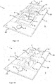
Fig. 1A-1C : perspektivische Ansichten und eine Querschnittsansicht einer ersten Ausführungsform einer Kochfeldanordnung; -
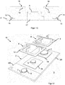
Fig. 2-4 : perspektivische Ansichten weiterer Ausführungsformen einer Kochfeldanordnung außerhalb des Bereichs der Erfindung; -
Fig. 5-7 : Schnittansichten von Ausführungsformen von Kochfeldplatten für Kochfeldanordnungen. - In der
Fig. 2 ist eine zweite Ausführungsform einer Kochfeldanordnung 10 außerhalb des Bereichs der Erfindung perspektivisch dargestellt. Man erkennt wiederum eine zweiteilige Kochfeldplatte 2, welche in eine Arbeitsplatte 3 ein- oder aufgesetzt ist. In der Orientierung derFig. 2 nach vorne hin ist ein Bedienfeldabschnitt 2B mit Bedienelement 6 und Anzeigevorrichtungen 7 dargestellt. Die Topfträger 8, 9 sind ähnlich den Topfträgern, wie es in derFig. 1 dargestellt ist, ausgeführt. Um die beiden Gasbrenner 4, 5 herum sind viereckige erhabene Flächen 18 als Auskragungen der Kochfeldplatte 2 zu erkennen. Die viereckigen erhabenen Flächen 18 werden von den Rahmen 14 der Topfträger 8, 9 im aufgesetzten Zustand umschlossen. - Ferner zeigt die
Fig. 3 eine dritte Ausführungsform einer Kochfeldanordnung 11 außerhalb des Bereichs der Erfindung, mit einer keramischen Kochfeldplatte 2. Die Kochfeldplatte 2 umfasst wiederum zwei Abschnitte für die Gasbrenner 2A und einen Abschnitt 2B für ein Bedienelement 6. Die Kochfeldplatte ist in eine Arbeitsplatte 3 ein- oder aufgesetzt. Um die beiden Gasbrenner 4, 5 bzw. um die in derFig. 3 nicht sichtbaren Öffnungen für die Gasbrenner 4, 5 herum, sind rechteckige Ausnehmungen 15 in der Kochfeldplatte 2 angedeutet. In die Ausnehmungen 15 lassen sich Topfträgerfüße 19 hineinstecken oder setzen. Die in derFig. 3 angedeuteten Topfträger 8, 9 weisen dabei kreuzförmige Auflageflächen für Gargutbehälter auf, wobei die Füße 19 senkrecht nach unten in Richtung zur Kochfeldplatte 2 reichen. Die Ausnehmungen oder Öffnungen 15 in der Kochfeldplatte 2 sind derart ausgeführt, dass die Fußelemente oder Topfträgerfüße 19 hineingesteckt werden können. Dadurch ergibt sich eine verrutsch- und verdrehsichere Anordnung der Topfträger 8, 9 ohne zusätzlich notwendige Befestigungsmechanismen. - Schließlich zeigt die
Fig. 4 eine vierte Ausführungsform einer Kochfeldanordnung 12 außerhalb des Bereichs der Erfindung. Es ist wiederum eine Kochfeldplatte 2 in oder auf eine Arbeitsplatte 3 eingesetzt. Dabei ist ein Bereich 2B für Bedienelemente 6 und der Bereich 2A für die Gasbrenner 4, 5 vorgesehen. Um die Gasbrenner 4, 5 bzw. die Öffnungen in der Glaskeramikblatte 2A herum sind im Wesentlichen quadratische Ausnehmungen oder Öffnungen 15 angeordnet. Die Topfträger 8, 9 sind jeweils aus vier Winkelelementen 23 geformt. Ein jeweiliges Winkelelement 23 hat dabei einen ersten und zweiten Schenkel 24, 25. Die Schenkel 24, 25 haben einen im Wesentlichen quadratischen Querschnitt. Die Winkelelemente 23 lassen sich mit dem ersten Schenkel 24 senkrecht in die jeweilige Ausnehmung 15 der Kochfeldplatte 2 einsetzen. Dazu sind optionale Halteeinsätze 26 vorgesehen, die in den Öffnungen 15 zur Stabilisierung eingestzt sind und die die senkrechten Schenkel 24 umschließen. Insofern verläuft der erste Schenkel 24 bei normalem Betriebszustand der Kochfeldanordnung 12 senkrecht. Rechtwinklig, also horizontal dazu verlaufen die zweiten Schenkel 25 der Winkelemente 23 und bilden eine Auflagefläche 16 für den jeweiligen Gargutbehälter.
Die Tiefe oder Größe der viereckigen Ausnehmung 15 zum Einstecken der ersten Schenkel 24 der Winkelelemente 23 kann dabei derart gewählt werden, dass eine ausreichende Stabilität der nach innen gerichteten Finger bzw. zweiten Schenkel 25 gewährleistet ist.
In derFig. 5 ist eine Querschnittsansicht einer mehrteilig ausgeführten Kochfeldplatte 2 dargestellt. DieFig. 5 zeigt dabei eine erste Platte 20 und eine zweite Platte 21. Die beiden Platten 20, 21 können aus Glaskeramik oder mineralischem Material gefertigt sein und aufeinander befestigt werden. Dabei kann eine Laminierung, Verklebung oder sonstige Verbindung erfolgen. Um eine Ausnehmung in der zweischichtigen oder zweilagigen Kochfeldplatte 2 zu erzielen, ist die zweite Platte 21 unterbrochen, so dass die Kanten 22 der zweiten Platte eine Kontur der Ausnehmung 15 vorgeben. - Die
Fig. 6 zeigt eine Querschnittsansicht einer materialeinstückigen Kochfeldplatte 2 außerhalb des Bereichs der Erfindung mit Auskragungen 18A, 18B.
Schließlich zeigt dieFig. 7 ebenfalls eine mehrschichtige oder mehrlagige Kochfeldplatte 2 außerhalb des Bereichs der Erfindung mit einer unteren Platte 20 auf die eine obere zweite Platte 21A, 21B befestigt ist. Die Konturen der zweiten Platte 21 definieren dabei die Auskragungen der gesamten Kochfeldplatte 2. Man erkennt, dass die Kanten 22 der zweiten oberen Platte 21 die Form der Auskragungen vorgeben.
Die Querschnitte oder Profile der Kochfeldplatten 2 können insbesondere bei der Verwendung von keramischen Materialien leicht fertigungstechnisch realisiert werden. Dies ist insbesondere bei der Verwendung von Cordierit der Fall, da bei der Fertigung zunächst eine Paste erzeugt wird, welche in die gewünschte Form und das gewünschte Profil der Kochfeldplatte angepasst werden kann. Insofern ergibt sich zum Beispiel eine materialeinstückige Kochfeldplatte mit Ausnehmungen und/oder Auskragungen, die zur Befestigung von Topfträgern dienen können. Durch den Verzicht auf zusätzliche Haltemechanismen können die Herstellungskosten der gesamten Kochfeldanordnung reduziert werden. Außerdem kann eine besonders ansprechende optische Erscheinung der Kochfelder realisiert werden.
Obwohl die vorliegende Erfindung anhand von Ausführungsbeispielen beschrieben wurde, ist sie vielfältig modifizierbar. -
- 1
- Kochfeldanordnung
- 2
- Kochfeldplatte
- 3
- Arbeitsplatte
- 4, 5
- Gasbrenner
- 6
- Bedienelement
- 7
- Anzeige
- 8, 9
- Topfträger
- 10, 11, 12
- Kochfeldanordnung
- 13
- Finger
- 14
- Topfträgerrahmen
- 15
- Ausnehmung
- 16
- Auflagefläche
- 17
- Gasbrenneröffnung
- 18
- Auskragung
- 19
- Topfträgerfuß
- 20, 21
- Platten
- 22
- Plattenkanten
- 23
- Winkelelement
- 24, 25
- Schenkel
- 26
- Halteeinsatz
In der
Die Kochfeldanordnung 1 umfasst dabei eine Kochfeldplatte 2, die beispielsweise in einer Arbeitsfläche 3 ein- oder aufgesetzt ist. Die Kochfeldplatte 2 ist dabei aus einem keramischen Werkstoff gefertigt. Keramische Werkstoffe sind beispielsweise Ausgangsmischungen mit Magnesium-Silikat-Hydrat, Kaolinit, kalzinierter Kaolinit und/oder reinem Aluminiumoxid. Die Kochfeldplatte kann auch insbesondere aus hochreinem synthetischen Cordierit gefertigt sein. Insbesondere die vorgenannten Mineralsilikate ermöglichen die Herstellung der Kochfeldplatte mit einer Ausgangsmischung aus einer homogenen Paste, welche in die gewünschte Form für die Kochfeldplatte gebracht werden kann.
In den Darstellungen ist die Kochfeldplatte 2 zweiteilig ausgeführt, wobei ein erster Abschnitt 2A zur Aufnahme von Gasbrennern 4, 5 vorgesehen ist und ein zweiter Teil 2B zur Aufnahme von Bedienelementen 6 und Anzeigen 7. Die Kochfeldanordnung 1 umfasst dabei zwei Gaskochstellen mit Gasbrennern 4, 5, die mit Topfträgern 8, 9 versehen sind. Die Topfträger 8, 9 umfassen dabei einen Rahmen 14, der auf die Kochfeldplatte 2 aufgesetzt wird. Nach innen von dem Rahmen 14 gerichtete Finger 13 bilden eine Auflagefläche 16 für einen Gargutbehälter, wie einen Topf oder eine Pfanne. Um die Topfträger 8 oder 9 verrutschsicher an oder auf der Kochfeldplatte 2 zu befestigen, sind um die Gasbrenner 4, 5 bzw. die hier nicht dargestellten Öffnungen für die Gasbrenner 4, 5 Ausnehmungen 15 in der Kochfeldplatte 2 vorgesehen. Die Ausnehmungen 15 sind als quadratisch umlaufende Nute, welche in der Form und Geometrie an die Rahmen der Topfträger 14 angepasst sind, gebildet.
In der
In der Querschnittsansicht der
Claims (11)
- Kochfeldanordnung (1), insbesondere Gaskochfeld, aufweisend eine Kochfeldplatte (2) mit einer Oberfläche und einer Öffnung (17) für mindestens einen Gasbrenner (4, 5) und einen Topfträger (8, 9), wobei die Kochfeldplatte (2) mindestens eine Ausnehmung (15) zur Halterung eines Rahmens (14) des Topfträgers (8, 9) umfasst und die Kochfeldplatte (2) zumindest teilweise aus einem keramischen Material gefertigt ist, wobei der Rahmen (14) des Topfträgers (8, 9) formschlüssig in die Ausnehmung (15) einsetzbar ist, so dass sich ein bündiger Abschluss der Oberfläche der Kochfeldplatte (2) mit dem Rahmen (14) des Topfträgers (8, 9) ergibt.
- Kochfeldanordnung (1) nach Anspruch 1, dadurch gekennzeichnet, dass die Kochfeldplatte (2) eine durch einen Materialabtrag gefertigte Ausnehmung (15) umfasst.
- Kochfeldanordnung (1) nach Anspruch 1 oder 2, dadurch gekennzeichnet, dass die Kochfeldplatte (2) zumindest teilweise aus Cordierit gefertigt ist.
- Kochfeldanordnung (1) nach einem der Ansprüche 1-3, dadurch gekennzeichnet, dass die Kochfeldplatte (2) mehrere aufeinander liegende Platten (20, 21) umfasst.
- Kochfeldanordnung (1) nach Anspruch 4, dadurch gekennzeichnet, dass die Platten (20,21) derart unterschiedliche Konturen haben, dass die Ausnehmung (15) von Kanten (22) der Platten (20, 21) umschlossen ist.
- Kochfeldanordnung (1) nach Anspruch 4 oder 5, dadurch gekennzeichnet, dass die Platten (20, 21) aufeinander verbunden sind.
- Kochfeldanordnung (1) nach einem der Ansprüche 1 - 6, dadurch gekennzeichnet, dass die Ausnehmung (14) um die Öffnung (17) für den Gasbrenner (4, 5) angeordnet ist.
- Kochfeldanordnung (1) nach einem der Ansprüche 1 - 7, dadurch gekennzeichnet, dass die Ausnehmung (14) als Nut oder Rinne um die Öffnung (17) für den Gasbrenner (4, 5) verläuft.
- Kochfeldanordnung (1) nach einem der Ansprüche 1 - 8, dadurch gekennzeichnet, dass der Topfträger (8, 9) mehrere Füße (19) zum Einsetzen in Ausnehmungen (15) in der Kochfeldplatte (2) umfasst.
- Kochfeldanordnung (1) nach einem der Ansprüche 1 - 9, dadurch gekennzeichnet, dass der Topfträger (8, 9) mehrere Winkelelemente (23) mit jeweils einem ersten Schenkel (24) und einem zweiten Schenkel (25) umfasst, wobei die ersten Schenkel (24) im Wesentlichen senkrecht in Ausnehmungen (15) der Kochfeldplatte (2) eingesetzt sind und die zweiten Schenkel (23) eine Auflagefläche (16) für einen Gargutbehälter bilden.
- Kochfeldanordnung (1) nach einem der Ansprüche 1 - 10, ferner mit mindestens einem Gasbrenner (4, 5).
Applications Claiming Priority (2)
| Application Number | Priority Date | Filing Date | Title |
|---|---|---|---|
| DE102011082735A DE102011082735A1 (de) | 2011-09-15 | 2011-09-15 | Kochfeldanordnung |
| PCT/EP2012/067182 WO2013037666A1 (de) | 2011-09-15 | 2012-09-04 | Kochfeldanordnung |
Publications (2)
| Publication Number | Publication Date |
|---|---|
| EP2756232A1 EP2756232A1 (de) | 2014-07-23 |
| EP2756232B1 true EP2756232B1 (de) | 2018-01-03 |
Family
ID=46801492
Family Applications (1)
| Application Number | Title | Priority Date | Filing Date |
|---|---|---|---|
| EP12756174.4A Active EP2756232B1 (de) | 2011-09-15 | 2012-09-04 | Kochfeldanordnung |
Country Status (4)
| Country | Link |
|---|---|
| EP (1) | EP2756232B1 (de) |
| DE (1) | DE102011082735A1 (de) |
| ES (1) | ES2656043T3 (de) |
| WO (1) | WO2013037666A1 (de) |
Citations (3)
| Publication number | Priority date | Publication date | Assignee | Title |
|---|---|---|---|---|
| WO2011134734A1 (de) * | 2010-04-27 | 2011-11-03 | BSH Bosch und Siemens Hausgeräte GmbH | Hitzeschild für ein gaskochfeld und gaskochfeld |
| WO2013083527A1 (de) * | 2011-12-09 | 2013-06-13 | BSH Bosch und Siemens Hausgeräte GmbH | Gaskochfeld |
| WO2013150004A1 (de) * | 2012-04-03 | 2013-10-10 | BSH Bosch und Siemens Hausgeräte GmbH | Topfträger und gaskochfeld |
Family Cites Families (5)
| Publication number | Priority date | Publication date | Assignee | Title |
|---|---|---|---|---|
| DE19905670A1 (de) * | 1998-12-16 | 2000-09-07 | Schott Glas | Kochgerät |
| DE20016145U1 (de) * | 2000-09-18 | 2001-01-18 | Schott Glas, 55122 Mainz | Kochfeld mit mindestens einem atmosphärischen Gasbrenner |
| DE10112234C1 (de) * | 2001-03-06 | 2002-07-25 | Schott Glas | Keramik-Kochfeld |
| DE10122093B4 (de) * | 2001-05-07 | 2005-03-24 | Schott Ag | Glas- oder Glaskeramikpaneel |
| DE20319629U1 (de) * | 2002-12-21 | 2004-03-11 | Schott Glas | Dreidimensionale Kochfeldeinheit aus Glaskeramik bzw. Glas |
-
2011
- 2011-09-15 DE DE102011082735A patent/DE102011082735A1/de not_active Withdrawn
-
2012
- 2012-09-04 WO PCT/EP2012/067182 patent/WO2013037666A1/de not_active Ceased
- 2012-09-04 ES ES12756174.4T patent/ES2656043T3/es active Active
- 2012-09-04 EP EP12756174.4A patent/EP2756232B1/de active Active
Patent Citations (3)
| Publication number | Priority date | Publication date | Assignee | Title |
|---|---|---|---|---|
| WO2011134734A1 (de) * | 2010-04-27 | 2011-11-03 | BSH Bosch und Siemens Hausgeräte GmbH | Hitzeschild für ein gaskochfeld und gaskochfeld |
| WO2013083527A1 (de) * | 2011-12-09 | 2013-06-13 | BSH Bosch und Siemens Hausgeräte GmbH | Gaskochfeld |
| WO2013150004A1 (de) * | 2012-04-03 | 2013-10-10 | BSH Bosch und Siemens Hausgeräte GmbH | Topfträger und gaskochfeld |
Also Published As
| Publication number | Publication date |
|---|---|
| WO2013037666A1 (de) | 2013-03-21 |
| ES2656043T3 (es) | 2018-02-22 |
| DE102011082735A1 (de) | 2013-03-21 |
| EP2756232A1 (de) | 2014-07-23 |
Similar Documents
| Publication | Publication Date | Title |
|---|---|---|
| EP2013033B1 (de) | Kochfeldplatteneinheit mit eingebettetem dekor | |
| EP2556304B1 (de) | Topfträger und gaskochstelle | |
| DE69821168T2 (de) | Kochmulde | |
| WO2009133003A2 (de) | Gaskochfeld sowie topfträger für ein gaskochfeld | |
| EP2476958A2 (de) | Topfträgeranordnung für ein Gaskochfeld und Gaskochfeld | |
| WO2008003566A2 (de) | Kochmulde | |
| EP2099257B1 (de) | Kochfeld | |
| EP2503248A1 (de) | Kochfeld mit einer Kochfeldplatte und einer Wanne zur Aufnahme einer Heizeinheit | |
| WO2013150004A1 (de) | Topfträger und gaskochfeld | |
| DE102011011738B4 (de) | Möbelsystem | |
| EP2476957B1 (de) | Gaskochfeld | |
| DE102011082735A1 (de) | Kochfeldanordnung | |
| DE20319629U1 (de) | Dreidimensionale Kochfeldeinheit aus Glaskeramik bzw. Glas | |
| WO2011151200A1 (de) | Verblendungsteil für ein haushaltsgerät, haushaltsgerät und verfahren zur herstellung eines verblendungsteils eines haushaltsgerätes | |
| DE102012208571A1 (de) | Kochfeldanordnung | |
| EP2337427A2 (de) | Induktionskochfeld mit zumindest einem Induktor und einer Bedienvorrichtung sowie Verfahren zum Herstellen eines Induktionskochfelds | |
| DE102012203380B4 (de) | Kochfeld mit einem Montagerahmen in einem Zierrahmen sowie Verfahren zum Herstellen eines Kochfelds | |
| DE102008042670B4 (de) | Hausgeräterahmen | |
| DE102005027198A1 (de) | Zusatztopfträger für Gaskochfelder | |
| EP2635848B1 (de) | Kochfeldanordnung | |
| EP1693621A1 (de) | Gaskochmulde | |
| EP2783163B1 (de) | Zierrahmen für ein haushaltsgerät, haushaltsgerät mit einem derartigen zierrahmen und verfahren zum herstellen eines zierrahmens | |
| AT525621B1 (de) | Flächenheizpaneel | |
| EP2758718A1 (de) | Tür für ein haushaltsgerät sowie haushaltsgerät, insbesondere gargerät | |
| DE102005055438A1 (de) | Kochmulde |
Legal Events
| Date | Code | Title | Description |
|---|---|---|---|
| PUAI | Public reference made under article 153(3) epc to a published international application that has entered the european phase |
Free format text: ORIGINAL CODE: 0009012 |
|
| 17P | Request for examination filed |
Effective date: 20140415 |
|
| AK | Designated contracting states |
Kind code of ref document: A1 Designated state(s): AL AT BE BG CH CY CZ DE DK EE ES FI FR GB GR HR HU IE IS IT LI LT LU LV MC MK MT NL NO PL PT RO RS SE SI SK SM TR |
|
| DAX | Request for extension of the european patent (deleted) | ||
| RAP1 | Party data changed (applicant data changed or rights of an application transferred) |
Owner name: BSH HAUSGERAETE GMBH |
|
| GRAP | Despatch of communication of intention to grant a patent |
Free format text: ORIGINAL CODE: EPIDOSNIGR1 |
|
| INTG | Intention to grant announced |
Effective date: 20170807 |
|
| GRAS | Grant fee paid |
Free format text: ORIGINAL CODE: EPIDOSNIGR3 |
|
| GRAA | (expected) grant |
Free format text: ORIGINAL CODE: 0009210 |
|
| AK | Designated contracting states |
Kind code of ref document: B1 Designated state(s): AL AT BE BG CH CY CZ DE DK EE ES FI FR GB GR HR HU IE IS IT LI LT LU LV MC MK MT NL NO PL PT RO RS SE SI SK SM TR |
|
| REG | Reference to a national code |
Ref country code: GB Ref legal event code: FG4D Free format text: NOT ENGLISH |
|
| REG | Reference to a national code |
Ref country code: CH Ref legal event code: EP Ref country code: AT Ref legal event code: REF Ref document number: 960645 Country of ref document: AT Kind code of ref document: T Effective date: 20180115 |
|
| REG | Reference to a national code |
Ref country code: IE Ref legal event code: FG4D Free format text: LANGUAGE OF EP DOCUMENT: GERMAN |
|
| REG | Reference to a national code |
Ref country code: NL Ref legal event code: FP |
|
| REG | Reference to a national code |
Ref country code: DE Ref legal event code: R096 Ref document number: 502012011948 Country of ref document: DE |
|
| REG | Reference to a national code |
Ref country code: ES Ref legal event code: FG2A Ref document number: 2656043 Country of ref document: ES Kind code of ref document: T3 Effective date: 20180222 |
|
| REG | Reference to a national code |
Ref country code: LT Ref legal event code: MG4D |
|
| PG25 | Lapsed in a contracting state [announced via postgrant information from national office to epo] |
Ref country code: CY Free format text: LAPSE BECAUSE OF FAILURE TO SUBMIT A TRANSLATION OF THE DESCRIPTION OR TO PAY THE FEE WITHIN THE PRESCRIBED TIME-LIMIT Effective date: 20180103 Ref country code: LT Free format text: LAPSE BECAUSE OF FAILURE TO SUBMIT A TRANSLATION OF THE DESCRIPTION OR TO PAY THE FEE WITHIN THE PRESCRIBED TIME-LIMIT Effective date: 20180103 Ref country code: FI Free format text: LAPSE BECAUSE OF FAILURE TO SUBMIT A TRANSLATION OF THE DESCRIPTION OR TO PAY THE FEE WITHIN THE PRESCRIBED TIME-LIMIT Effective date: 20180103 Ref country code: NO Free format text: LAPSE BECAUSE OF FAILURE TO SUBMIT A TRANSLATION OF THE DESCRIPTION OR TO PAY THE FEE WITHIN THE PRESCRIBED TIME-LIMIT Effective date: 20180403 Ref country code: HR Free format text: LAPSE BECAUSE OF FAILURE TO SUBMIT A TRANSLATION OF THE DESCRIPTION OR TO PAY THE FEE WITHIN THE PRESCRIBED TIME-LIMIT Effective date: 20180103 |
|
| PG25 | Lapsed in a contracting state [announced via postgrant information from national office to epo] |
Ref country code: GR Free format text: LAPSE BECAUSE OF FAILURE TO SUBMIT A TRANSLATION OF THE DESCRIPTION OR TO PAY THE FEE WITHIN THE PRESCRIBED TIME-LIMIT Effective date: 20180404 Ref country code: PL Free format text: LAPSE BECAUSE OF FAILURE TO SUBMIT A TRANSLATION OF THE DESCRIPTION OR TO PAY THE FEE WITHIN THE PRESCRIBED TIME-LIMIT Effective date: 20180103 Ref country code: RS Free format text: LAPSE BECAUSE OF FAILURE TO SUBMIT A TRANSLATION OF THE DESCRIPTION OR TO PAY THE FEE WITHIN THE PRESCRIBED TIME-LIMIT Effective date: 20180103 Ref country code: BG Free format text: LAPSE BECAUSE OF FAILURE TO SUBMIT A TRANSLATION OF THE DESCRIPTION OR TO PAY THE FEE WITHIN THE PRESCRIBED TIME-LIMIT Effective date: 20180403 Ref country code: IS Free format text: LAPSE BECAUSE OF FAILURE TO SUBMIT A TRANSLATION OF THE DESCRIPTION OR TO PAY THE FEE WITHIN THE PRESCRIBED TIME-LIMIT Effective date: 20180503 Ref country code: SE Free format text: LAPSE BECAUSE OF FAILURE TO SUBMIT A TRANSLATION OF THE DESCRIPTION OR TO PAY THE FEE WITHIN THE PRESCRIBED TIME-LIMIT Effective date: 20180103 Ref country code: LV Free format text: LAPSE BECAUSE OF FAILURE TO SUBMIT A TRANSLATION OF THE DESCRIPTION OR TO PAY THE FEE WITHIN THE PRESCRIBED TIME-LIMIT Effective date: 20180103 |
|
| PG25 | Lapsed in a contracting state [announced via postgrant information from national office to epo] |
Ref country code: MT Free format text: LAPSE BECAUSE OF FAILURE TO SUBMIT A TRANSLATION OF THE DESCRIPTION OR TO PAY THE FEE WITHIN THE PRESCRIBED TIME-LIMIT Effective date: 20180103 |
|
| REG | Reference to a national code |
Ref country code: DE Ref legal event code: R097 Ref document number: 502012011948 Country of ref document: DE |
|
| PG25 | Lapsed in a contracting state [announced via postgrant information from national office to epo] |
Ref country code: RO Free format text: LAPSE BECAUSE OF FAILURE TO SUBMIT A TRANSLATION OF THE DESCRIPTION OR TO PAY THE FEE WITHIN THE PRESCRIBED TIME-LIMIT Effective date: 20180103 Ref country code: AL Free format text: LAPSE BECAUSE OF FAILURE TO SUBMIT A TRANSLATION OF THE DESCRIPTION OR TO PAY THE FEE WITHIN THE PRESCRIBED TIME-LIMIT Effective date: 20180103 Ref country code: EE Free format text: LAPSE BECAUSE OF FAILURE TO SUBMIT A TRANSLATION OF THE DESCRIPTION OR TO PAY THE FEE WITHIN THE PRESCRIBED TIME-LIMIT Effective date: 20180103 |
|
| PLBE | No opposition filed within time limit |
Free format text: ORIGINAL CODE: 0009261 |
|
| STAA | Information on the status of an ep patent application or granted ep patent |
Free format text: STATUS: NO OPPOSITION FILED WITHIN TIME LIMIT |
|
| PG25 | Lapsed in a contracting state [announced via postgrant information from national office to epo] |
Ref country code: DK Free format text: LAPSE BECAUSE OF FAILURE TO SUBMIT A TRANSLATION OF THE DESCRIPTION OR TO PAY THE FEE WITHIN THE PRESCRIBED TIME-LIMIT Effective date: 20180103 Ref country code: SM Free format text: LAPSE BECAUSE OF FAILURE TO SUBMIT A TRANSLATION OF THE DESCRIPTION OR TO PAY THE FEE WITHIN THE PRESCRIBED TIME-LIMIT Effective date: 20180103 Ref country code: CZ Free format text: LAPSE BECAUSE OF FAILURE TO SUBMIT A TRANSLATION OF THE DESCRIPTION OR TO PAY THE FEE WITHIN THE PRESCRIBED TIME-LIMIT Effective date: 20180103 Ref country code: SK Free format text: LAPSE BECAUSE OF FAILURE TO SUBMIT A TRANSLATION OF THE DESCRIPTION OR TO PAY THE FEE WITHIN THE PRESCRIBED TIME-LIMIT Effective date: 20180103 |
|
| 26N | No opposition filed |
Effective date: 20181005 |
|
| PG25 | Lapsed in a contracting state [announced via postgrant information from national office to epo] |
Ref country code: SI Free format text: LAPSE BECAUSE OF FAILURE TO SUBMIT A TRANSLATION OF THE DESCRIPTION OR TO PAY THE FEE WITHIN THE PRESCRIBED TIME-LIMIT Effective date: 20180103 |
|
| REG | Reference to a national code |
Ref country code: DE Ref legal event code: R119 Ref document number: 502012011948 Country of ref document: DE |
|
| PG25 | Lapsed in a contracting state [announced via postgrant information from national office to epo] |
Ref country code: MC Free format text: LAPSE BECAUSE OF FAILURE TO SUBMIT A TRANSLATION OF THE DESCRIPTION OR TO PAY THE FEE WITHIN THE PRESCRIBED TIME-LIMIT Effective date: 20180103 |
|
| REG | Reference to a national code |
Ref country code: CH Ref legal event code: PL |
|
| GBPC | Gb: european patent ceased through non-payment of renewal fee |
Effective date: 20180904 |
|
| REG | Reference to a national code |
Ref country code: BE Ref legal event code: MM Effective date: 20180930 |
|
| REG | Reference to a national code |
Ref country code: IE Ref legal event code: MM4A |
|
| PG25 | Lapsed in a contracting state [announced via postgrant information from national office to epo] |
Ref country code: LU Free format text: LAPSE BECAUSE OF NON-PAYMENT OF DUE FEES Effective date: 20180904 |
|
| PG25 | Lapsed in a contracting state [announced via postgrant information from national office to epo] |
Ref country code: DE Free format text: LAPSE BECAUSE OF NON-PAYMENT OF DUE FEES Effective date: 20190402 Ref country code: IE Free format text: LAPSE BECAUSE OF NON-PAYMENT OF DUE FEES Effective date: 20180904 |
|
| PG25 | Lapsed in a contracting state [announced via postgrant information from national office to epo] |
Ref country code: FR Free format text: LAPSE BECAUSE OF NON-PAYMENT OF DUE FEES Effective date: 20180930 Ref country code: CH Free format text: LAPSE BECAUSE OF NON-PAYMENT OF DUE FEES Effective date: 20180930 Ref country code: LI Free format text: LAPSE BECAUSE OF NON-PAYMENT OF DUE FEES Effective date: 20180930 Ref country code: BE Free format text: LAPSE BECAUSE OF NON-PAYMENT OF DUE FEES Effective date: 20180930 |
|
| PG25 | Lapsed in a contracting state [announced via postgrant information from national office to epo] |
Ref country code: GB Free format text: LAPSE BECAUSE OF NON-PAYMENT OF DUE FEES Effective date: 20180904 |
|
| PGFP | Annual fee paid to national office [announced via postgrant information from national office to epo] |
Ref country code: NL Payment date: 20190923 Year of fee payment: 8 Ref country code: IT Payment date: 20190920 Year of fee payment: 8 |
|
| REG | Reference to a national code |
Ref country code: AT Ref legal event code: MM01 Ref document number: 960645 Country of ref document: AT Kind code of ref document: T Effective date: 20180904 |
|
| PG25 | Lapsed in a contracting state [announced via postgrant information from national office to epo] |
Ref country code: AT Free format text: LAPSE BECAUSE OF NON-PAYMENT OF DUE FEES Effective date: 20180904 |
|
| PG25 | Lapsed in a contracting state [announced via postgrant information from national office to epo] |
Ref country code: PT Free format text: LAPSE BECAUSE OF FAILURE TO SUBMIT A TRANSLATION OF THE DESCRIPTION OR TO PAY THE FEE WITHIN THE PRESCRIBED TIME-LIMIT Effective date: 20180103 Ref country code: HU Free format text: LAPSE BECAUSE OF FAILURE TO SUBMIT A TRANSLATION OF THE DESCRIPTION OR TO PAY THE FEE WITHIN THE PRESCRIBED TIME-LIMIT; INVALID AB INITIO Effective date: 20120904 |
|
| PG25 | Lapsed in a contracting state [announced via postgrant information from national office to epo] |
Ref country code: MK Free format text: LAPSE BECAUSE OF NON-PAYMENT OF DUE FEES Effective date: 20180103 |
|
| REG | Reference to a national code |
Ref country code: NL Ref legal event code: MM Effective date: 20201001 |
|
| PG25 | Lapsed in a contracting state [announced via postgrant information from national office to epo] |
Ref country code: NL Free format text: LAPSE BECAUSE OF NON-PAYMENT OF DUE FEES Effective date: 20201001 |
|
| PG25 | Lapsed in a contracting state [announced via postgrant information from national office to epo] |
Ref country code: IT Free format text: LAPSE BECAUSE OF NON-PAYMENT OF DUE FEES Effective date: 20200904 |
|
| PGFP | Annual fee paid to national office [announced via postgrant information from national office to epo] |
Ref country code: TR Payment date: 20230829 Year of fee payment: 12 |
|
| PGFP | Annual fee paid to national office [announced via postgrant information from national office to epo] |
Ref country code: ES Payment date: 20231019 Year of fee payment: 12 |
|
| REG | Reference to a national code |
Ref country code: ES Ref legal event code: FD2A Effective date: 20251024 |
|
| PG25 | Lapsed in a contracting state [announced via postgrant information from national office to epo] |
Ref country code: ES Free format text: LAPSE BECAUSE OF NON-PAYMENT OF DUE FEES Effective date: 20240905 |