EP1010948A1 - Kochgerät - Google Patents
Kochgerät Download PDFInfo
- Publication number
- EP1010948A1 EP1010948A1 EP99122367A EP99122367A EP1010948A1 EP 1010948 A1 EP1010948 A1 EP 1010948A1 EP 99122367 A EP99122367 A EP 99122367A EP 99122367 A EP99122367 A EP 99122367A EP 1010948 A1 EP1010948 A1 EP 1010948A1
- Authority
- EP
- European Patent Office
- Prior art keywords
- glass
- ceramic plate
- foot
- glass ceramic
- cooking appliance
- Prior art date
- Legal status (The legal status is an assumption and is not a legal conclusion. Google has not performed a legal analysis and makes no representation as to the accuracy of the status listed.)
- Granted
Links
Images


Classifications
-
- F—MECHANICAL ENGINEERING; LIGHTING; HEATING; WEAPONS; BLASTING
- F24—HEATING; RANGES; VENTILATING
- F24C—DOMESTIC STOVES OR RANGES ; DETAILS OF DOMESTIC STOVES OR RANGES, OF GENERAL APPLICATION
- F24C3/00—Stoves or ranges for gaseous fuels
- F24C3/08—Arrangement or mounting of burners
- F24C3/085—Arrangement or mounting of burners on ranges
-
- F—MECHANICAL ENGINEERING; LIGHTING; HEATING; WEAPONS; BLASTING
- F24—HEATING; RANGES; VENTILATING
- F24C—DOMESTIC STOVES OR RANGES ; DETAILS OF DOMESTIC STOVES OR RANGES, OF GENERAL APPLICATION
- F24C15/00—Details
- F24C15/10—Tops, e.g. hot plates; Rings
- F24C15/107—Pan supports or grates therefor
Definitions
- the invention relates to a cooking appliance with a Glass / glass ceramic plate, the at least one hotplate with a gas burner with an open flame, a pot holder with feet and one Space for a cookware is mechanically fixed centrally.
- Cooking appliances with a glass ceramic plate as the cooking surface and cooking zones electrically heated have been on the market for more than two decades. These glass ceramic hobs are valued primarily because of the attractive appearance, flat surface and easy cleaning. Because of of the clear and valued advantages that glass ceramics call Cooking surface material has been used for several years now tries to use this material with gas cooking appliances or with cooking appliances electrically heated cooking zones combined with so-called gas burners Mixed devices.
- the second type uses common atmospheric gas burners, i.e. such with open flame, inserted through holes in the glass ceramic plate.
- the above-described cooking appliances with a glass / glass ceramic plate that at least have a hotplate with a gas burner with an open flame need a pan support that has a footprint for the cookware has feet attached to it on the glass / glass ceramic plate get up.
- These pot supports must be so that the energy transfer from the Burner to the cookware is optimal, centered to the gas burner aligned and fixed in this position.
- the invention is based, based on the task designated cooking device for this a pot support centering and fixation to create the inexpensive and flexible to manufacture and easy to clean is.
- the cooking appliance can also do so be trained that the foot mounts by grinding in the Glass / glass ceramic plate, adapted to the contour of the foot ends are formed.
- the foot mounts also do not have to be in the material of the Glass / glass ceramic plate itself.
- the arrangement can also be so be taken that the foot mounts through with a recess for the Fixed mounting of the foot ends provided on the glass / glass ceramic plate attached separate foot holder are formed.
- These separate footrest components can be made relatively easily and can be made on the trained in various ways and at the Glass / glass ceramic plate can be attached.
- the foot holder can be made in one piece and be attached as a whole to the glass / glass ceramic plate. A Cleaning of these foot supports must then be carried out "in situ", i.e. when attached, respectively.
- the foot holder is made in two parts with a base part that is attached to the glass / glass ceramic plate and with a top part removable from the base part.
- the removable upper part can then be cleaned separately from the cooking device, e.g. also in the dishwasher.
- the Invention in a one-piece design of the foot holder as a whole and in In the case of the two-part design, the base part on the cooking surface side Glass / glass ceramic plate should be glued on.
- suitable adhesives with permanent adhesive properties are available (e.g. high temperature resistant silicone adhesive).
- the arrangement can also be so be made that the foot holder attachment side an extension have, in corresponding holes in the glass / glass ceramic plate is mechanically fixed.
- the extension of the foot holder can also be in the corresponding holes are clamped by means of a spring by the Extension formations, preferably a groove structure, for clamping Introducing the extension into a socket in the bore.
- the foot supports according to the invention which have been characterized so far have depressions in which the feet of the pot holder rest. These cuts can, as shown, by lowered formations or grinding be formed in the glass / glass ceramic plate itself, or can corresponding reductions in separate moldings that are on the Glass / glass ceramic plate are applied.
- an alternative embodiment is given that the foot mounts by bulges on the Glass / glass ceramic plate are formed.
- the bulges protruding upwards on the cooking side can open up can be realized in different ways.
- the bulges can already be advantageous during the manufacture of the Glass / glass ceramic plate are formed, i.e. immediately in the material the glass / glass ceramic plate itself be formed by according to a further embodiment of the invention, the bulges by raised molded forms are formed in the glass / glass ceramic plate, the rise from the kitchen side or alternatively by the bulges due to protruding thickenings in the glass / glass ceramic plate are formed.
- the bulges can either selectively in the area of Pot support feet as their installation points or alternatively as be formed rotationally symmetrical around the ring around the gas burner.
- the circumferential ring can overcook in the Retain the burner area and prevent it from spreading over the entire area Spreads the cooking surface.
- the cooking appliance is designed that the footprint of the pot support feet to the contour of the bulge is adjusted.
- the pot support feet can be positioned the cooking device be designed so that on the footprint of the Pot support feet each have a pin and one each on the bulge appropriate holes for receiving the pin are made. Further Variants are marked in subclaims.
- Fig. 1 shows a gas burning point of a cooking appliance with a Glass ceramic plate 1 as a cooking surface, which has an opening 2 in which a atmospheric burner 3 of conventional design with symbolically indicated Flames 3 a is recorded and bordered with a ring sleeve 4 is.
- the burner 3 is a conventional pot support 5 with a footprint 5 a and feet 5 b assigned, on which the respective, schematically illustrated Cookware 6, a pot, a pan or the like stands.
- FIGS. 1 shows only a single gas burning point of a cooking appliance and it is understood that the cooking appliance has several such gas burning points can. So-called mixed cooking devices can also be provided with a combination of at least one gas burner according to FIGS. 1 and at least one electrically heated cooking zone.
- the burner 3 Via a feed pipe 3 a, the burner 3, depending on the design of the Brenners a pure gas that later mixed with the so-called primary air or a mixture (pre-mix) of gas and the primary air is supplied. This gas mixture burns in the space 9 between the glass-ceramic plate 1 and bottom of the cookware 6, the exhaust gases between the legs of the Drain the pot holder 5 through to the outside.
- the pot support 5 is directly on the Glass ceramic plate 1. It must be there to ensure optimal combustion or Securing energy transfer, fixed to the gas burner 3 be positioned, which is indicated in Fig. 1 by a principle Foot bracket 7 is expressed, the stationary on the Glass ceramic plate 1 is attached and the foot 5 b of the pot support 5 fixed records.
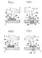
- FIG. 2 shows an embodiment in which the foot holder 7 of FIG. 1 formed by a lowered formation 1 a in the glass ceramic plate 1 is, in connection with a complementary thickening 5 c at the end of the foot 5 b of the pot holder.
- the geometry of the formation and the Thickening can be designed, and can be done selectively in the area of the feet 5b - or else a rotationally symmetrical formation 1 a accept. In the first case there are indentations, in the other case it is there is a circumferential groove.
- the shape can also be on the extend the entire thickness of the plate 1, i.e. the plate 1 then has Forming area the same thickness as in the flat area. In this case would the molding area immediately during the manufacture of the Pronounced glass ceramic plate. In the other case, the shape would be Grinding or the like.
- Fig. 3 shows an alternative embodiment in which the foot bracket through a grinding or stamping 1 b in the glass ceramic plate 1 in Connection with a complementary training 5 d at the end of Foot 5 b of the pot carrier is formed.
- the expression can be punctual or dent or be circumferentially formed as a groove.
- Foot mounts such as those with a separate, button-type foot mounts that open on is mechanically connected to the glass ceramic plate in various ways.
- FIG. 4 shows a one-piece footrest button 12 with a trough-shaped recess 12 a in connection with one to the Trough complementary foot end 5 e.
- the foot holder button 12 is glued to the glass ceramic plate 1 as it is the adhesive seam 13 is clarified.
- the foot holder button is 12 not glued to the glass ceramic plate 1, but has an extension 12 b on, which is received in a hole 1 c in the glass ceramic plate.
- the extension on the other side of the glass ceramic plate fixed with a spring washer.
- extension 12 b can also be replaced by a appropriate training of extension 12 b with a thread on the The underside can be screwed in.
- the extension is also glued in place an elastic adhesive possible.
- the foot holder button Made in two parts, each with a base part 14, which is indicated in Fig. 6 glued to the glass ceramic plate by the adhesive seam 13, analogously to FIG. 4 is, and in the embodiment of FIG. 7 with an extension 14 b in one Bore 1 c of the glass ceramic plate 1 is mechanically fastened, similar to that 5.
- the foot holder button also has an upper part 15 that e.g. Removable via a positive connection with the base part 14 connected is.
- the upper part 15 each has an angular recess in these examples 14 a, in which the complementary end 5 f of the foot 5 b is recorded.
- FIGS. 8 to 11 further possibilities are now available described, which are all based on the principle that the foot mounts 7th are formed by bulges on the glass / glass ceramic plate 1.
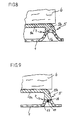
- Fig. 8 shows a bulge, which is formed by a raised Expression 16 is formed in the glass ceramic plate 1, which extends from the cooking side this raises.
- This arched shape 16 can run concentrically to the gas burner 3 as a ring-wall-like ring or selectively dome-shaped his.
- the foot end 5 b is complementary to the curvature, this partially encompassing, concave and positioned or fixed in this way the pan support 5.
- a bulge 17 is analogous 8 directly formed in the glass ceramic plate 1, the however, in contrast to the bulge 16 in Fig. 8 flattened at the top is, as is the foot end 5 b of the pot carrier 5.
- the pot support is at the foot end 5 b a pin 18 and a bore in the bulge 17 in the flattened part 19 designed to receive the pin 18.
- the bulge 17 can be punctiform or as a circumferential ring wall be trained.
- FIG. 11 with a cross-sectional view of the Foot holder 7 in part A is a bulge 22 with a recess 23 provided that complementary to a nose-shaped projection 24 Foot end 5 b is.
- This projection 24 has the same function as the pin 18 in Fig. 9, i.e. fixes the pan support.
- the bulge 22 can also are formed selectively or as a circumferential ring.
- the circumferential ring wall that is possible in all embodiments keeps up Advantage possible overflow in the burner area back and prevents this spreads over the entire cooking surface.
- buttons-like foot holders can be provided in different ways are mechanically connectable to the glass ceramic plate, according to the Designs according to Figures 4 to 7.
Landscapes
- Engineering & Computer Science (AREA)
- Chemical & Material Sciences (AREA)
- Combustion & Propulsion (AREA)
- Mechanical Engineering (AREA)
- General Engineering & Computer Science (AREA)
- Cookers (AREA)
- Baking, Grill, Roasting (AREA)
Abstract
Description
- Fig. 1
- in einer Schnittansicht eine Gasbrennstelle mit einem Topfträger, der erfindungsgemäß mit seinen Füßen von ortsfest auf der Glaskeramikplatte ausgebildeten Fußhalterungen aufgenommen ist,
- Fig. 2
- in einer vergrößerten Ausschnittdarstellung zur Fig. 1 eine Ausführungsform der Fußhalterung mit einer abgesenkten Ausformung in der Glaskeramikplatte in Verbindung mit einem halbkugelförmig ausgebildeten Fußende,
- Fig. 3
- eine Ausschnittdarstellung entsprechend Fig. 2, jedoch mit einer Ausbildung der Fußhalterung durch eine Ausschleifung in der Glaskeramikplatte in Verbindung mit einem dazu komplementären Fußende des Topfträgers,
- Fig. 4
- in einer entsprechenden Ausschnittsdarstellung eine Fußhalterung mit einem separaten, einteiligen knopfartigen Fußhalter, der auf die Glaskeramikplatte aufgeklebt ist,
- Fig. 5
- in einer Darstellung entsprechend Fig. 4 die Ausführung der Fußhalterung mit einem einteiligen knopfartigen Fußhalter, der einen Fortsatz aufweist, mit dem er in einer Bohrung in der Glaskeramikplatte verklemmt ist,
- Fig. 6
- eine Ausführungsform entsprechend derjenigen nach Fig. 4, jedoch mit einer zweiteiligen Ausführung des Fußhalters mit abnehmbaren Oberteil, und
- Fig. 7
- eine Ausführungsform entsprechen derjenigen nach Fig. 5, jedoch ebenfalls mit einer zweiteiligen Ausführung des Fußhalters nach Fig. 6,
- Fig. 8
- in einer vergrößerten Ausschnittsdarstellung zur Fig. 1 eine alternative Ausführungsform der Fußhalterung mit einer aufgewölbten Ausformung in der Glaskeramikplatte in Verbindung mit einem zur Aufwölbung konkav ausgebildeten Fußende,
- Fig. 9
- eine Ausschnittsdarstellung entsprechend Fig. 8, jedoch mit einer oberen Abflachung der Aufwölbung, auf der ein flaches Fußende mit einem Zapfen positioniert ist,
- Fig. 10
- eine Ausschnittsdarstellung entsprechend Fig. 8 mit einer Aufwölbung in der Glaskeramikplatte in Form einer Verdickung, und
- Fig. 11
- eine Ausschnittdarstellung entsprechend Fig. 8 mit einer aufgewölbten Ausformung in der Glaskeramikplatte, die eine Ausnehmung zur Positionierung des dazu komplementär ausgebildeten Fußendes besitzt.
Claims (14)
- Kochgerät mit einer Glas-/Glaskeramikplatte (1), das mindestens eine Kochstelle mit einem Gasbrenner (3) mit offener Flamme (3 a) aufweist, dem ein Topfträger (5) mit Füßen (5 b) und einer Aufstellfläche für ein Kochgeschirr (6) zentrisch mechanisch fixiert zuordenbar ist, dadurch gekennzeichnet, daß die Glas-/Glaskeramikplatte (1) ortsfest ausgebildete Fußhalterungen (7) für den Topfträger (5) aufweist.
- Kochgerät nach Anspruch 1, dadurch gekennzeichnet, daß die Fußhalterungen (7) durch abgesenkte Ausformungen (1 a) in der Glas-/Glaskeramikplatte (1), angepaßt an die Kontur der Fußenden (5 c) gebildet sind (Fig. 2).
- Kochgerät nach Anspruch 1, dadurch gekennzeichnet, daß die Fußhalterungen (7) durch Ausschleifungen (1 b) in der Glas-/Glaskeramikplatte (1), angepaßt an die Kontur der Fußenden (5 d) gebildet sind (Fig. 3).
- Kochgerät nach Anspruch 2 oder 3, dadurch gekennzeichnet, daß die Ausformungen (la) oder die Ausschleifungen (1b) punktuell im Bereich der Fußenden (5c) oder umlaufend als Rille ausgebildet sind.
- Kochgerät nach Anspruch 1, dadurch gekennzeichnet, daß die Fußhalterungen (7) durch mit einer Ausnehmung (12 a; 14 a) für die fixierte Aufnahme der Fußenden (5 e, f) versehene, an der Glas-/Glaskeramikplatte (1) angebrachte separate Fußhalter (12; 14; 15) gebildet sind.
- Kochgerät nach Anspruch 5, dadurch gekennzeichnet, daß die Fußhalter (12) einteilig ausgebildet sind (Fig. 4, 5).
- Kochgerät nach Anspruch 5, dadurch gekennzeichnet, daß die Fußhalter (14, 15) zweiteilig ausgebildet sind, mit einem Basisteil (14), das an der Glas-/Glaskeramikplatte (1) befestigt ist und mit einem von dem Basisteil (14) abnehmbaren Oberteil (15) (Fig. 6, 7).
- Kochgerät nach Anspruch 5, oder 6, 7, dadurch gekennzeichnet, daß die Fußhalter (12; 14; 15) kochflächenseitig auf die Glaskeramikplatte (1) aufgeklebt sind oder befestigungsseitig einen Fortsatz (12 b; 14 b) aufweisen, der jeweils in entsprechenden Bohrungen (1 c) in der Glas-/Glaskeramikplatte (1) mechanisch fixiert aufgenommen ist.
- Kochgerät nach Anspruch 1, dadurch gekennzeichnet, daß die Fußhalterungen (7) durch Aufwölbungen (16, 17, 20, 22) auf der Glas-/Glaskeramikplatte (1) gebildet sind.
- Kochgerät nach Anspruch 9, dadurch gekennzeichnet, daß die Aufwölbungen durch erhaben ausgeformte Ausprägungen (16, 17, 22) in der Glas-/Glaskeramikplatte (1) gebildet sind, die sich kochseitig aus dieser erheben.
- Kochgerät nach Anspruch 9, dadurch gekennzeichnet, daß die Aufwölbungen durch kochseitig überstehende Verdickungen (20) in der Glas-/Glaskeramikplatte (1) gebildet sind.
- Kochgerät nach Anspruch 9, dadurch gekennzeichnet, daß die Aufwölbungen durch erhaben ausgeformte, kochseitig überstehende Konturen von separaten Formteilen gebildet sind, die an der Glas-/Glaskeramikplatte fest angebracht sind.
- Kochgerät nach einem der Ansprüche 9 bis 12, dadurch gekennzeichnet, daß die Aufstellfläche der Topfträgerfüße (5 b) an die Kontur der Auswölbung (16, 17, 20, 22) angepaßt ist.
- Kochgerät nach Anspruch 13, dadurch gekennzeichnet, daß an der Aufstellfläche der Topfträgerfüße (5 b) jeweils ein Zapfen (18) und an der Aufwölbung (17) jeweils eine entsprechende Bohrung (19) zur Aufnahme des Zapfens angebracht ist, oder jeweils eine nasenförmige Anformung (24) und an der Aufwölbung (22) jweils eine dazu komplementäre Ausnehmung (23) ausgebildet sind.
Applications Claiming Priority (4)
| Application Number | Priority Date | Filing Date | Title |
|---|---|---|---|
| DE19858019 | 1998-12-16 | ||
| DE1998158019 DE19858019A1 (de) | 1998-12-16 | 1998-12-16 | Kochgerät |
| DE19905670A DE19905670A1 (de) | 1998-12-16 | 1999-02-11 | Kochgerät |
| DE19905670 | 1999-02-11 |
Publications (2)
| Publication Number | Publication Date |
|---|---|
| EP1010948A1 true EP1010948A1 (de) | 2000-06-21 |
| EP1010948B1 EP1010948B1 (de) | 2003-05-21 |
Family
ID=26050788
Family Applications (1)
| Application Number | Title | Priority Date | Filing Date |
|---|---|---|---|
| EP99122367A Expired - Lifetime EP1010948B1 (de) | 1998-12-16 | 1999-11-10 | Kochgerät |
Country Status (5)
| Country | Link |
|---|---|
| US (2) | US6279567B1 (de) |
| EP (1) | EP1010948B1 (de) |
| JP (1) | JP4195762B2 (de) |
| DE (2) | DE19905670A1 (de) |
| PL (1) | PL337153A1 (de) |
Cited By (5)
| Publication number | Priority date | Publication date | Assignee | Title |
|---|---|---|---|---|
| WO2013037666A1 (de) * | 2011-09-15 | 2013-03-21 | BSH Bosch und Siemens Hausgeräte GmbH | Kochfeldanordnung |
| DE202014004210U1 (de) | 2013-11-05 | 2014-07-21 | Schott Ag | Kochfläche mit einer Glas- oder Glaskeramikplatte mit einer Verbindung mit einem Bauteil aus einem metallischen Material |
| EP2743589A3 (de) * | 2012-12-12 | 2015-06-24 | BSH Hausgeräte GmbH | Kochgerät mit Brenner |
| CN104791863A (zh) * | 2015-05-07 | 2015-07-22 | 冯世英 | 燃气灶的支架式挡火板 |
| CN104791865A (zh) * | 2015-05-07 | 2015-07-22 | 冯世英 | 燃气灶的支架式挡火板的制造和使用方法 |
Families Citing this family (17)
| Publication number | Priority date | Publication date | Assignee | Title |
|---|---|---|---|---|
| DE50012344D1 (de) * | 2000-02-10 | 2006-05-04 | Wenko Wenselaar Gmbh | Kochfeldabdeckplatte |
| ITTO20020101U1 (it) * | 2002-05-20 | 2003-11-20 | Merloni Elettrodomestici Spa | Bruciatore di gas per piano di cottura domestico. |
| US20050056268A1 (en) * | 2003-09-17 | 2005-03-17 | General Electric Company | Gas burner for a cooking appliance |
| DE102005026210A1 (de) * | 2005-06-07 | 2006-12-28 | BSH Bosch und Siemens Hausgeräte GmbH | Gaskochfeld |
| DE102007041907A1 (de) * | 2007-09-04 | 2009-03-05 | BSH Bosch und Siemens Hausgeräte GmbH | Kochfeld und Verfahren zum Herstellen eines Kochfeldes |
| ES2339839B1 (es) * | 2008-06-10 | 2011-03-10 | Bsh Electrodomesticos España, S.A. | Campo de coccion. |
| USD604559S1 (en) | 2009-06-03 | 2009-11-24 | Mark Woodruff | Saucepan support |
| US9612021B2 (en) * | 2010-06-24 | 2017-04-04 | Bsh Home Appliances Corporation | Compressive stabilizing grate foot for home appliance |
| ES2621792T3 (es) * | 2011-11-04 | 2017-07-05 | Electrolux Home Products Corporation N.V. | Conjunto de quemador de gas, placa de cocina de gas y electrodoméstico con quemadores de gas |
| ES2668806T3 (es) * | 2011-11-10 | 2018-05-22 | Electrolux Home Products Corporation N.V. | Rejilla de quemador, placa de cocinado de gas, parte superior de cocina de gas y cocina de gas |
| WO2013098010A1 (en) | 2011-12-26 | 2013-07-04 | Arcelik Anonim Sirketi | A cooker |
| EP2798275B1 (de) | 2011-12-26 | 2016-07-20 | Arçelik Anonim Sirketi | Kocher |
| ES2442968A1 (es) * | 2012-08-14 | 2014-02-14 | BSH Electrodomésticos España S.A. | Tapa de quemador y soporte de olla para un punto de cocción a gas, punto de cocción a gas y campo de cocción a gas |
| ES2442969A1 (es) * | 2012-08-14 | 2014-02-14 | BSH Electrodomésticos España S.A. | Placa de cubierta con soporte de olla integrado para un punto de cocción a gas, punto de cocción a gas y campo de cocción a gas |
| CN104654365B (zh) * | 2015-01-22 | 2017-08-04 | 广东美的厨房电器制造有限公司 | 燃气灶 |
| US9795251B2 (en) | 2015-06-24 | 2017-10-24 | Joshua Rosecrans | Detachable external heating device for an outdoor grill or smoker |
| US11859829B2 (en) | 2021-12-03 | 2024-01-02 | Whirlpool Corporation | Cooktop grate assembly |
Citations (7)
| Publication number | Priority date | Publication date | Assignee | Title |
|---|---|---|---|---|
| US3830216A (en) * | 1971-03-15 | 1974-08-20 | Owens Illinois Inc | Countertop heating apparatus |
| US5046477A (en) * | 1990-12-28 | 1991-09-10 | Amana Refrigeration Inc. | Gas cook-top with glass top |
| EP0551235A1 (de) * | 1992-01-10 | 1993-07-14 | Compagnie Europeenne Pour L'equipement Menager "Cepem" | Atmosphärischer Gaskochbrenner mit Primärluftzufuhr von der Unterseite einer Kochmulde |
| DE19505469C1 (de) | 1995-02-17 | 1996-02-08 | Schott Glaswerke | Anordnung für die Zuführung von Primärluft zu einem atmosphärischen Gasbrenner über einer Kochplatte aus Glaskeramik |
| DE19505470A1 (de) * | 1995-02-17 | 1996-08-22 | Schott Glaswerke | Topfträger für Gaskochmulden |
| DE4326945C2 (de) | 1993-08-11 | 1996-10-24 | Schott Glaswerke | Regeleinrichtung für die Gaszufuhr zu einer Gaskocheinrichtung mit unter einer durchgehenden Kochfläche angeordneten Gasstrahlungsbrennern |
| DE29805620U1 (de) * | 1998-03-27 | 1998-05-14 | Schott Glas, 55122 Mainz | Kochmulde mit einem Gasbrenner |
Family Cites Families (13)
| Publication number | Priority date | Publication date | Assignee | Title |
|---|---|---|---|---|
| US2530183A (en) * | 1944-12-30 | 1950-11-14 | Servel Inc | Cooking range |
| US2485145A (en) * | 1945-04-09 | 1949-10-18 | Grand Ind Inc | Combination burner and grate |
| US3592180A (en) * | 1969-05-05 | 1971-07-13 | Inst Gas Technology | Gas burner device |
| US3625196A (en) | 1970-05-05 | 1971-12-07 | W J Schoenberger Co The | Burner cap assembly |
| US4089321A (en) * | 1976-02-06 | 1978-05-16 | Ondrasik Ii Vladimir J | Constraining grate |
| DE2930456A1 (de) * | 1978-10-03 | 1980-04-10 | Atag Bv Apparatenfab | Kochrost |
| US4261327A (en) * | 1979-04-06 | 1981-04-14 | Magic Chef, Inc. | Range grate and clip |
| DE3003830A1 (de) | 1980-02-02 | 1981-08-13 | Neff - Werke, Carl Neff Gmbh, 7518 Bretten | Gas-kochmulde |
| DE8414673U1 (de) * | 1984-05-14 | 1984-09-20 | EKU-Metallbau Gastro-Großküchen-Center Egon Kulbach, 6250 Limburg | Glatte arbeitsplatte mit eingelassenenn gasbeheizten kochstellen, betrieben mit brennern, denen ringfoermige roste, aufgesetzt auf herdschuessel, zugeordnet sind: diese speziell geeignet fuer kugelfoermige gefaesse |
| US4593677A (en) * | 1985-07-29 | 1986-06-10 | Magic Chef | Range grate and retaining clip assembly |
| WO1989005944A1 (de) * | 1989-01-23 | 1989-06-29 | Eku-Metallbau, Gastro-Grossküchencenter | Glatte arbeitsplatte mit eingelassenen kochstellen, insbesondere eines gasherdes |
| DE4133409C2 (de) * | 1991-10-09 | 1993-10-21 | Schott Glaswerke | Brenneranordnung |
| FR2735562B1 (fr) * | 1995-06-19 | 1997-08-14 | Eurokera | Plaque de cuisson au gaz en vitroceramique et procede pour sa fabrication |
-
1999
- 1999-02-11 DE DE19905670A patent/DE19905670A1/de not_active Withdrawn
- 1999-11-10 DE DE59905635T patent/DE59905635D1/de not_active Expired - Lifetime
- 1999-11-10 EP EP99122367A patent/EP1010948B1/de not_active Expired - Lifetime
- 1999-12-13 PL PL99337153A patent/PL337153A1/xx not_active Application Discontinuation
- 1999-12-14 US US09/460,694 patent/US6279567B1/en not_active Expired - Lifetime
- 1999-12-16 JP JP35679599A patent/JP4195762B2/ja not_active Expired - Lifetime
-
2001
- 2001-05-15 US US09/855,263 patent/US6470879B1/en not_active Expired - Lifetime
Patent Citations (7)
| Publication number | Priority date | Publication date | Assignee | Title |
|---|---|---|---|---|
| US3830216A (en) * | 1971-03-15 | 1974-08-20 | Owens Illinois Inc | Countertop heating apparatus |
| US5046477A (en) * | 1990-12-28 | 1991-09-10 | Amana Refrigeration Inc. | Gas cook-top with glass top |
| EP0551235A1 (de) * | 1992-01-10 | 1993-07-14 | Compagnie Europeenne Pour L'equipement Menager "Cepem" | Atmosphärischer Gaskochbrenner mit Primärluftzufuhr von der Unterseite einer Kochmulde |
| DE4326945C2 (de) | 1993-08-11 | 1996-10-24 | Schott Glaswerke | Regeleinrichtung für die Gaszufuhr zu einer Gaskocheinrichtung mit unter einer durchgehenden Kochfläche angeordneten Gasstrahlungsbrennern |
| DE19505469C1 (de) | 1995-02-17 | 1996-02-08 | Schott Glaswerke | Anordnung für die Zuführung von Primärluft zu einem atmosphärischen Gasbrenner über einer Kochplatte aus Glaskeramik |
| DE19505470A1 (de) * | 1995-02-17 | 1996-08-22 | Schott Glaswerke | Topfträger für Gaskochmulden |
| DE29805620U1 (de) * | 1998-03-27 | 1998-05-14 | Schott Glas, 55122 Mainz | Kochmulde mit einem Gasbrenner |
Cited By (5)
| Publication number | Priority date | Publication date | Assignee | Title |
|---|---|---|---|---|
| WO2013037666A1 (de) * | 2011-09-15 | 2013-03-21 | BSH Bosch und Siemens Hausgeräte GmbH | Kochfeldanordnung |
| EP2743589A3 (de) * | 2012-12-12 | 2015-06-24 | BSH Hausgeräte GmbH | Kochgerät mit Brenner |
| DE202014004210U1 (de) | 2013-11-05 | 2014-07-21 | Schott Ag | Kochfläche mit einer Glas- oder Glaskeramikplatte mit einer Verbindung mit einem Bauteil aus einem metallischen Material |
| CN104791863A (zh) * | 2015-05-07 | 2015-07-22 | 冯世英 | 燃气灶的支架式挡火板 |
| CN104791865A (zh) * | 2015-05-07 | 2015-07-22 | 冯世英 | 燃气灶的支架式挡火板的制造和使用方法 |
Also Published As
| Publication number | Publication date |
|---|---|
| US6279567B1 (en) | 2001-08-28 |
| PL337153A1 (en) | 2000-06-19 |
| JP4195762B2 (ja) | 2008-12-10 |
| EP1010948B1 (de) | 2003-05-21 |
| DE59905635D1 (de) | 2003-06-26 |
| JP2000179857A (ja) | 2000-06-27 |
| US6470879B1 (en) | 2002-10-29 |
| DE19905670A1 (de) | 2000-09-07 |
Similar Documents
| Publication | Publication Date | Title |
|---|---|---|
| EP1010948B1 (de) | Kochgerät | |
| EP0945681B1 (de) | Kochmulde mit einem Gasbrenner | |
| DE19505469C1 (de) | Anordnung für die Zuführung von Primärluft zu einem atmosphärischen Gasbrenner über einer Kochplatte aus Glaskeramik | |
| DE10012578C2 (de) | Kochfeld | |
| DE60312832T2 (de) | Kochfeld aus vorgespanntem glas oder anderen wärmeabbauenden materialien | |
| DE3440868A1 (de) | Kochmulde | |
| DE69830753T2 (de) | Tiefgezogene brennvorichtung | |
| DE19705715C1 (de) | Kochgerät | |
| DE29805620U1 (de) | Kochmulde mit einem Gasbrenner | |
| DE19861078C2 (de) | Gaskochgerät | |
| DE19819732C1 (de) | Anordnung zur Befestigung eines atmosphärischen Gasbrenners an der Brenneröffnung einer Kochfläche aus Glas oder Glaskeramik sowie Kochfeld mit einer solchen Anordnung | |
| DE19505470C2 (de) | Topfträger für Gaskochmulden | |
| DE60025033T2 (de) | Kochplatte | |
| DE69206501T2 (de) | Infrarotstrahlungsbrenner für Glaskeramik-Kochmulde. | |
| WO2001039645A1 (de) | Gaskochgerät | |
| DE19733242C1 (de) | Gas-Kochfeld mit einem plattenförmigen Formkörper aus sprödbrüchigem Material | |
| DE19858019A1 (de) | Kochgerät | |
| DE10029632A1 (de) | Topfträger für atmosphärische Gasbrenner in Glas-/Glaskeramikkochfeldern | |
| EP1005254A2 (de) | Kochfeld mit Positionierungselement für einen Heizkörper | |
| EP0990853B1 (de) | Gaskochgerät | |
| DE2915529C3 (de) | Einbau-Kochfeld mit einer Kochplatte aus glaskeramischem Material | |
| DE102010063473B4 (de) | Gaskochgerät mit einem Topfträger | |
| DE10056987C1 (de) | Gaskochgerät | |
| DE102005027198A1 (de) | Zusatztopfträger für Gaskochfelder | |
| EP1502055A1 (de) | Brennerdeckel für einen gasbrenner, gasbrenner sowie gaskochmulde |
Legal Events
| Date | Code | Title | Description |
|---|---|---|---|
| PUAI | Public reference made under article 153(3) epc to a published international application that has entered the european phase |
Free format text: ORIGINAL CODE: 0009012 |
|
| 17P | Request for examination filed |
Effective date: 19991110 |
|
| AK | Designated contracting states |
Kind code of ref document: A1 Designated state(s): AT BE CH CY DE DK ES FI FR GB GR IE IT LI LU MC NL PT SE |
|
| AX | Request for extension of the european patent |
Free format text: AL;LT;LV;MK;RO;SI |
|
| AKX | Designation fees paid |
Free format text: AT BE CH CY DE DK ES FI FR GB GR IE IT LI LU MC NL PT SE |
|
| 17Q | First examination report despatched |
Effective date: 20020313 |
|
| GRAH | Despatch of communication of intention to grant a patent |
Free format text: ORIGINAL CODE: EPIDOS IGRA |
|
| RAP1 | Party data changed (applicant data changed or rights of an application transferred) |
Owner name: CARL-ZEISS-STIFTUNG TRADING AS SCHOTT GLAS Owner name: SCHOTT GLAS |
|
| GRAH | Despatch of communication of intention to grant a patent |
Free format text: ORIGINAL CODE: EPIDOS IGRA |
|
| RAP1 | Party data changed (applicant data changed or rights of an application transferred) |
Owner name: SCHOTT GLAS |
|
| GRAA | (expected) grant |
Free format text: ORIGINAL CODE: 0009210 |
|
| RBV | Designated contracting states (corrected) |
Designated state(s): DE FR |
|
| AK | Designated contracting states |
Designated state(s): DE FR |
|
| REG | Reference to a national code |
Ref country code: IE Ref legal event code: FG4D Free format text: GERMAN |
|
| REF | Corresponds to: |
Ref document number: 59905635 Country of ref document: DE Date of ref document: 20030626 Kind code of ref document: P |
|
| REG | Reference to a national code |
Ref country code: IE Ref legal event code: FD4D Ref document number: 1010948E Country of ref document: IE |
|
| ET | Fr: translation filed | ||
| PLBE | No opposition filed within time limit |
Free format text: ORIGINAL CODE: 0009261 |
|
| STAA | Information on the status of an ep patent application or granted ep patent |
Free format text: STATUS: NO OPPOSITION FILED WITHIN TIME LIMIT |
|
| 26N | No opposition filed |
Effective date: 20040224 |
|
| REG | Reference to a national code |
Ref country code: FR Ref legal event code: TP |
|
| REG | Reference to a national code |
Ref country code: FR Ref legal event code: PLFP Year of fee payment: 17 |
|
| PGFP | Annual fee paid to national office [announced via postgrant information from national office to epo] |
Ref country code: DE Payment date: 20151119 Year of fee payment: 17 |
|
| REG | Reference to a national code |
Ref country code: FR Ref legal event code: PLFP Year of fee payment: 18 |
|
| REG | Reference to a national code |
Ref country code: DE Ref legal event code: R119 Ref document number: 59905635 Country of ref document: DE |
|
| REG | Reference to a national code |
Ref country code: FR Ref legal event code: PLFP Year of fee payment: 19 |
|
| PG25 | Lapsed in a contracting state [announced via postgrant information from national office to epo] |
Ref country code: DE Free format text: LAPSE BECAUSE OF NON-PAYMENT OF DUE FEES Effective date: 20170601 |
|
| PGFP | Annual fee paid to national office [announced via postgrant information from national office to epo] |
Ref country code: FR Payment date: 20181123 Year of fee payment: 20 |