EP2746858A2 - Bilderzeugungsvorrichtung mit Unterdrückung des Auftretens von Farbverschiebung in Bildern und Verfahren zur Steuerung davon - Google Patents
Bilderzeugungsvorrichtung mit Unterdrückung des Auftretens von Farbverschiebung in Bildern und Verfahren zur Steuerung davon Download PDFInfo
- Publication number
- EP2746858A2 EP2746858A2 EP13197796.9A EP13197796A EP2746858A2 EP 2746858 A2 EP2746858 A2 EP 2746858A2 EP 13197796 A EP13197796 A EP 13197796A EP 2746858 A2 EP2746858 A2 EP 2746858A2
- Authority
- EP
- European Patent Office
- Prior art keywords
- image bearing
- bearing means
- intermediate transfer
- image
- exposure
- Prior art date
- Legal status (The legal status is an assumption and is not a legal conclusion. Google has not performed a legal analysis and makes no representation as to the accuracy of the status listed.)
- Withdrawn
Links
- 238000000034 method Methods 0.000 title claims description 82
- 238000012546 transfer Methods 0.000 claims abstract description 320
- 230000008569 process Effects 0.000 description 51
- 238000010586 diagram Methods 0.000 description 45
- 238000001514 detection method Methods 0.000 description 32
- 239000003086 colorant Substances 0.000 description 28
- 230000000630 rising effect Effects 0.000 description 26
- 230000015572 biosynthetic process Effects 0.000 description 20
- 230000009467 reduction Effects 0.000 description 10
- 230000001133 acceleration Effects 0.000 description 8
- 230000001052 transient effect Effects 0.000 description 7
- 230000008859 change Effects 0.000 description 6
- 238000007786 electrostatic charging Methods 0.000 description 6
- 238000006073 displacement reaction Methods 0.000 description 5
- 238000013461 design Methods 0.000 description 4
- 230000014509 gene expression Effects 0.000 description 4
- 230000007246 mechanism Effects 0.000 description 4
- 238000004886 process control Methods 0.000 description 4
- 238000012545 processing Methods 0.000 description 4
- 238000012937 correction Methods 0.000 description 3
- 230000007547 defect Effects 0.000 description 3
- 238000012935 Averaging Methods 0.000 description 2
- 238000006243 chemical reaction Methods 0.000 description 2
- 238000011161 development Methods 0.000 description 2
- 230000000694 effects Effects 0.000 description 2
- 238000005070 sampling Methods 0.000 description 2
- 238000007600 charging Methods 0.000 description 1
- 238000010276 construction Methods 0.000 description 1
- 230000007423 decrease Effects 0.000 description 1
- 230000001788 irregular Effects 0.000 description 1
- 238000005259 measurement Methods 0.000 description 1
- 238000012986 modification Methods 0.000 description 1
- 230000004048 modification Effects 0.000 description 1
- 238000000465 moulding Methods 0.000 description 1
- 230000002093 peripheral effect Effects 0.000 description 1
- 230000001360 synchronised effect Effects 0.000 description 1
Images






Classifications
-
- G—PHYSICS
- G03—PHOTOGRAPHY; CINEMATOGRAPHY; ANALOGOUS TECHNIQUES USING WAVES OTHER THAN OPTICAL WAVES; ELECTROGRAPHY; HOLOGRAPHY
- G03G—ELECTROGRAPHY; ELECTROPHOTOGRAPHY; MAGNETOGRAPHY
- G03G15/00—Apparatus for electrographic processes using a charge pattern
- G03G15/04—Apparatus for electrographic processes using a charge pattern for exposing, i.e. imagewise exposure by optically projecting the original image on a photoconductive recording material
- G03G15/043—Apparatus for electrographic processes using a charge pattern for exposing, i.e. imagewise exposure by optically projecting the original image on a photoconductive recording material with means for controlling illumination or exposure
-
- G—PHYSICS
- G03—PHOTOGRAPHY; CINEMATOGRAPHY; ANALOGOUS TECHNIQUES USING WAVES OTHER THAN OPTICAL WAVES; ELECTROGRAPHY; HOLOGRAPHY
- G03G—ELECTROGRAPHY; ELECTROPHOTOGRAPHY; MAGNETOGRAPHY
- G03G15/00—Apparatus for electrographic processes using a charge pattern
- G03G15/01—Apparatus for electrographic processes using a charge pattern for producing multicoloured copies
- G03G15/0105—Details of unit
- G03G15/0131—Details of unit for transferring a pattern to a second base
-
- G—PHYSICS
- G03—PHOTOGRAPHY; CINEMATOGRAPHY; ANALOGOUS TECHNIQUES USING WAVES OTHER THAN OPTICAL WAVES; ELECTROGRAPHY; HOLOGRAPHY
- G03G—ELECTROGRAPHY; ELECTROPHOTOGRAPHY; MAGNETOGRAPHY
- G03G15/00—Apparatus for electrographic processes using a charge pattern
- G03G15/01—Apparatus for electrographic processes using a charge pattern for producing multicoloured copies
- G03G15/0142—Structure of complete machines
- G03G15/0178—Structure of complete machines using more than one reusable electrographic recording member, e.g. one for every monocolour image
- G03G15/0189—Structure of complete machines using more than one reusable electrographic recording member, e.g. one for every monocolour image primary transfer to an intermediate transfer belt
-
- G—PHYSICS
- G03—PHOTOGRAPHY; CINEMATOGRAPHY; ANALOGOUS TECHNIQUES USING WAVES OTHER THAN OPTICAL WAVES; ELECTROGRAPHY; HOLOGRAPHY
- G03G—ELECTROGRAPHY; ELECTROPHOTOGRAPHY; MAGNETOGRAPHY
- G03G15/00—Apparatus for electrographic processes using a charge pattern
- G03G15/50—Machine control of apparatus for electrographic processes using a charge pattern, e.g. regulating differents parts of the machine, multimode copiers, microprocessor control
- G03G15/5008—Driving control for rotary photosensitive medium, e.g. speed control, stop position control
-
- H—ELECTRICITY
- H04—ELECTRIC COMMUNICATION TECHNIQUE
- H04N—PICTORIAL COMMUNICATION, e.g. TELEVISION
- H04N1/00—Scanning, transmission or reproduction of documents or the like, e.g. facsimile transmission; Details thereof
- H04N1/46—Colour picture communication systems
- H04N1/56—Processing of colour picture signals
- H04N1/60—Colour correction or control
- H04N1/6077—Colour balance, e.g. colour cast correction
-
- G—PHYSICS
- G03—PHOTOGRAPHY; CINEMATOGRAPHY; ANALOGOUS TECHNIQUES USING WAVES OTHER THAN OPTICAL WAVES; ELECTROGRAPHY; HOLOGRAPHY
- G03G—ELECTROGRAPHY; ELECTROPHOTOGRAPHY; MAGNETOGRAPHY
- G03G21/00—Arrangements not provided for by groups G03G13/00 - G03G19/00, e.g. cleaning, elimination of residual charge
- G03G21/14—Electronic sequencing control
- G03G21/145—Electronic sequencing control wherein control pulses are generated by the mechanical movement of parts of the machine, e.g. the photoconductor
-
- G—PHYSICS
- G03—PHOTOGRAPHY; CINEMATOGRAPHY; ANALOGOUS TECHNIQUES USING WAVES OTHER THAN OPTICAL WAVES; ELECTROGRAPHY; HOLOGRAPHY
- G03G—ELECTROGRAPHY; ELECTROPHOTOGRAPHY; MAGNETOGRAPHY
- G03G2215/00—Apparatus for electrophotographic processes
- G03G2215/01—Apparatus for electrophotographic processes for producing multicoloured copies
- G03G2215/0151—Apparatus for electrophotographic processes for producing multicoloured copies characterised by the technical problem
- G03G2215/0158—Colour registration
Definitions
- the present invention relates to an electrophotographic image forming apparatus that suppresses occurrence of color shift in images and a method of controlling the same.
- Residual toner remaining on the photosensitive drums 100 is scraped and collected by respective cleaner blades 104.
- Residual toner remaining on the intermediate transfer member 108 is scraped and collected by an intermediate transfer member cleaner 109.
- the color image transferred onto the recording sheet P is fixed on the recording sheet P with pressure and temperature applied by the fixing device 113.
- a host CPU 1 collectively controls the start and stop of respective processes in a print process, such as charging, exposure, development, and application of high voltage in primary transfer, and other various setting values.
- a drum rotational position-detecting section 6 detects a rotational position.
- each image bearing member is provided with an image bearing member rotary encoder which uses the rotational shaft of the associated image bearing member as an input shaft.
- the electrical arrangement for driving the intermediate transfer member 108 including the host CPU 1, the control unit 2, an intermediate transfer member motor driver IC (denoted as “ITB MOTOR DRIVER IC” in FIG. 3 ) 88, an intermediate transfer member-driving circuit (denoted as “ITB-DRIVING CIRCUIT” in FIG. 3 ) 94, and an intermediate transfer member rotational position-detecting section (denoted as “ITB ROTATIONAL POSITION-DETECTING SECTION” in FIG. 3 ) 86 is the same as that for driving each photosensitive drum 100.
- the exposure device 101 connected to the control unit 2 comprises an LED head 101a, an LED driver circuit 101b that drives LED elements, and a light amount adjustment section 101c. Further, a controller 60 is configured to output image data to the control unit 2.
- the LED head 101a is formed by arranging a plurality of small LED elements LED1 to LEDN in a main scanning direction.
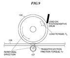
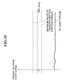
- this transient change component (hereinafter referred to as the "varying torque component”) is sufficiently small with respect to the load torque which is constantly generated.
- the varying torque component by applying the same amount of rotational torque as that of a DC-like component of the load torque to the photosensitive drum 100 using the drum brushless DC motor 5, it is possible to offset the DC-like component of the load torque generated on the photosensitive drum 100.
- applied rotational torque is referred to as the assist torque.
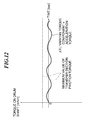
- the vertical axis represents the load torque generated on the drum shaft 9, and the horizontal axis represents time.
- the varying torque component which undergoes AC-like variation, is not larger than the maximum value T F of the transfer section friction torque TF, the photosensitive drum 100 can be friction-driven by the intermediate transfer member 108.
- the drum brushless DC motor 5 is used as a generation source of the assist torque, this is not limitative, but any other component may be employed insofar as it is capable of generating constant torque.
- the duty ratio When the duty ratio is large, the amount of electric current applied to each phase increases, whereas when the duty ratio is small, the amount of electric current applied to the phase decreases.
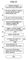
- the magnitude of the phase current is equivalent to torque generated in the motor. Since the magnitude of the phase current is proportional to the duty ratio, the duty ratio can be regarded as torque generated by the motor. Further, to detect the load torque on the drum shaft 9 generated during the print process, it is necessary to control the photosensitive drums 100 to rotate at the target process speed.
- a varying torque component of load in the image formation process is sufficiently small compared with a constantly generated component of the load, and hence in calculating the assist torque, the image forming apparatus may be in an idling state.
- the CPU 13 stops sampling of the duty ratio, stops operating the exposure devices 101, and stops high-voltage power supply to the electrostatic charging rollers 105, the developing devices 102, and the primary transfer rollers 107. Then, the CPU 13 causes the photosensitive drums 100 to rotate through once or two revolutions, and stops driving of the photosensitive drums 100 by outputting a drive stop command (step S7).
- the photosensitive drums 100 are rotated through one or two revolutions so as to remove toner on the photosensitive drums 100 by the cleaner blades 104.
- the rotational speed of the photosensitive drums 100 is converted to the surface speed V s based on the detection value from the drum rotary encoder 7, and a sub scanning exposure timing interval ⁇ t is calculated by dividing ⁇ L by V s .
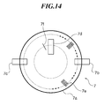
- FIG. 14 is a schematic diagram of the drum rotary encoder 7 appearing in FIG. 2 .
- ⁇ t ⁇ L ⁇ V S
- ⁇ t the sub scanning exposure timing interval
- ⁇ L a target sub scanning direction pitch distance
- V S a surface speed converted from the rotary encoder detection value
- the ROM 14 stores in advance a first target value which is a value calculated, as expressed by the above equation (6), by multiplying the first distance L Y of the reference image bearing member (photosensitive drum 100Y) by the number (800) of pulses to be output from the image bearing member rotary encoder for one revolution, and dividing the resulting multiplication product by the circumference (2 ⁇ R) of the image bearing member.
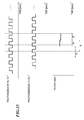
- the timing of starting counting the number of input pulses (rising edges thereof) from the intermediate rotary encoder 87 is a timing at which the number of pulses output from the image bearing member rotary encoder, which is counted by a count unit, becomes equal to the first target value N Y .
- the ROM 14 stores in advance second target values which are values calculated, as expressed by the above equations (7), (8), and (9), by subtracting values calculated by multiplying the first distances (L M , L C , L K ) by the number (800) of pulses to be output from the associated image bearing member rotary encoders for one revolution and dividing the resulting multiplication products by the circumference (2 ⁇ R) of each image bearing member, from values calculated by multiplying the second distances (D YM , D YC , D YK ) associated with the image bearing members (photosensitive drums 100M, 100C, 100K) other than the reference image bearing member (photosensitive drum 100Y) by the number (800) of pulses to be output from the intermediate transfer member rotary encoder for one revolution and dividing the resulting multiplication products by the circumference (2 ⁇ R) of a rotating member (intermediate transfer member-driving roller 110), respectively.
- second target values are values calculated, as expressed by the above equations (7), (8), and (9),
- FIG. 18 is a flowchart of a print process executed by the control unit 2 appearing in FIG. 5 .
- step S201 when the controller 60 receives a print operation command, the controller 60 outputs a command signal for starting various process controls to the host CPU 1. At the same time, image data is input from the controller 60 to the control unit 2 (step S201).
- the radius of each photosensitive drum 100 is measured in advance, or is measured on an as-needed basis. Further, a mechanism for detecting a specific surface position is preferably employed. As a method of detecting a specific surface position, to begin with, the surface of each photosensitive drum 100 is divided into areas corresponding in number to the slits 7e of the rotary encoder and each area is associated with each slit 7e.
- a drum-to-drum distance D (i.e. distance between primary transfer positions of respective photosensitive drums 100) does not change unless any of the photosensitive drum 100 is displaced, and hence the drum-to-drum distance D is set to a fixed value.
- the calculation is performed by setting the drum-to-drum distance D to a fixed value in this example, if the drum-to-drum distance D varies, by additionally calculating a variation of the drum-to-drum distance D, the above calculation can be similarly performed.
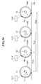
- the curves D YM -L M , D YC -L C , and D YK -L K each form a fluctuating curve. Further, a curve indicating the movement distance of the intermediate transfer member 108 which friction-drives the photosensitive drums 100 has a similar form.
- R Y (n), R M (n), R C (n), and R K (n) are stored in the ROM 14 in advance. These values are first physical amounts for determining the surface movement distance of the image bearing member according to each pulse output from the image bearing member rotary encoder.
- the CPU 13 continues to calculate the distances L M , L C , and L K from the respective exposure light irradiated positions to the primary transfer positions of the photosensitive drums 100.
- an angle ⁇ formed by the exposure light irradiated position, denoted by A, and the first transfer position, denoted by B, on the drum rotary encoder 7 is indicated.
- the angle ⁇ is a design value and hence is a predetermined fixed value.
- the distance L is a value obtained by adding up the surface distances z n according to a range of the pulse edge number n to a pulse edge number n + S. Note that the encoder pulse edge number n depends on a rotational angle of each photosensitive drum 100, and hence is different between the photosensitive drums 100.
- FIG. 24 is a timing diagram showing a relationship between the image formation start signal and the exposure control start timing for starting exposure of the photosensitive drums of the respective colors.
- the target distances TD M , TD C , and TD K for the photosensitive drums 100M, 100C, 100K after the start of exposure on the photosensitive drum 100Y are calculated using the drum rotary encoder 7Y provided on the photosensitive drum 100Y.
- the photosensitive drums 100 of the respective colors are completely friction-driven by the intermediate transfer member 108, all the movement distances calculated for the photosensitive drums are always the same, and hence they may be calculated using another photosensitive drum 100 or the intermediate transfer member 108.
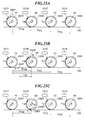
- FIGS. 25A to 25C are diagrams showing image leading edge positions of the respective colors.
- a Y-image leading edge position is denoted by 200Y
- an M-image leading edge position is denoted by 200M.
- a distance from the Y-image leading edge position 200Y to the primary transfer position of the photosensitive drum 100M is equal to L M .
- the C-image and K-image leading edge positions do not exist because the associated photosensitive drums are not exposed yet at this time.
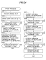
- FIG. 27 is a flowchart of a print process executed by the CPU 13 of the control unit 2 of the image forming apparatus according to the third embodiment.
- the CPU 13 starts to add an associated surface distance whenever a pulse edge of the signal from the intermediate transfer member rotary encoder 87 is detected, to thereby newly start to calculate a surface movement distance (step S507).
- the CPU 13 When the calculated surface movement distance becomes equal to the target distance TD' C calculated by the equation (21) (YES to a step S510), the CPU 13 outputs a CLK signal and a PWM signal to the exposure device 101C as control signals (step S511).
- the subsequent sub scanning exposure is determined according to the sub scanning exposure timing interval ⁇ t.
Landscapes
- Physics & Mathematics (AREA)
- General Physics & Mathematics (AREA)
- Engineering & Computer Science (AREA)
- Multimedia (AREA)
- Signal Processing (AREA)
- Microelectronics & Electronic Packaging (AREA)
- Color Electrophotography (AREA)
- Control Or Security For Electrophotography (AREA)
- Printers Or Recording Devices Using Electromagnetic And Radiation Means (AREA)
Applications Claiming Priority (2)
| Application Number | Priority Date | Filing Date | Title |
|---|---|---|---|
| JP2012275680 | 2012-12-18 | ||
| JP2013159385A JP2014139651A (ja) | 2012-12-18 | 2013-07-31 | 画像形成装置 |
Publications (2)
| Publication Number | Publication Date |
|---|---|
| EP2746858A2 true EP2746858A2 (de) | 2014-06-25 |
| EP2746858A3 EP2746858A3 (de) | 2017-08-16 |
Family
ID=49765414
Family Applications (1)
| Application Number | Title | Priority Date | Filing Date |
|---|---|---|---|
| EP13197796.9A Withdrawn EP2746858A3 (de) | 2012-12-18 | 2013-12-17 | Bilderzeugungsvorrichtung mit Unterdrückung des Auftretens von Farbverschiebung in Bildern und Verfahren zur Steuerung davon |
Country Status (4)
| Country | Link |
|---|---|
| US (1) | US9280081B2 (de) |
| EP (1) | EP2746858A3 (de) |
| JP (1) | JP2014139651A (de) |
| CN (1) | CN103869650A (de) |
Families Citing this family (5)
| Publication number | Priority date | Publication date | Assignee | Title |
|---|---|---|---|---|
| JP2014119649A (ja) * | 2012-12-18 | 2014-06-30 | Canon Inc | 画像形成装置 |
| US9696648B2 (en) * | 2015-01-15 | 2017-07-04 | Ricoh Company, Ltd. | Image forming apparatus |
| JP2016147450A (ja) * | 2015-02-13 | 2016-08-18 | キヤノン株式会社 | 画像形成装置 |
| CN106372565A (zh) * | 2015-07-23 | 2017-02-01 | 南京滕识电子科技有限公司 | 一种基于pid控制算法的三路调光手指静脉图像采集装置 |
| JP2024017813A (ja) * | 2022-07-28 | 2024-02-08 | キヤノン株式会社 | 駆動装置および記録装置 |
Citations (2)
| Publication number | Priority date | Publication date | Assignee | Title |
|---|---|---|---|---|
| JPH0899437A (ja) | 1994-09-30 | 1996-04-16 | Toshiba Corp | 画像形成装置 |
| JP2002333752A (ja) | 2001-02-16 | 2002-11-22 | Nexpress Solutions Llc | 摩擦駆動において適合部材を使用するための方法及びその装置 |
Family Cites Families (7)
| Publication number | Priority date | Publication date | Assignee | Title |
|---|---|---|---|---|
| US5381167A (en) * | 1991-10-24 | 1995-01-10 | Konica Corporation | Color image forming apparatus |
| JP3234878B2 (ja) * | 1994-09-29 | 2001-12-04 | 株式会社東芝 | 画像形成装置 |
| JPH09329936A (ja) * | 1996-06-13 | 1997-12-22 | Matsushita Electric Ind Co Ltd | 画像形成装置 |
| US6507713B2 (en) * | 2000-03-27 | 2003-01-14 | Ricoh Company, Ltd. | Image-formation apparatus, controlling method thereof and image-formation method |
| US6252618B1 (en) * | 2000-06-15 | 2001-06-26 | Lexmark International, Inc. | Method of controlling print registration in an electrophotographic machine |
| JP2003237144A (ja) * | 2001-12-10 | 2003-08-27 | Canon Inc | 画像処理装置及び画像処理方法及び制御プログラム及び記録媒体 |
| JP4735654B2 (ja) * | 2008-03-28 | 2011-07-27 | ブラザー工業株式会社 | 画像形成装置 |
-
2013
- 2013-07-31 JP JP2013159385A patent/JP2014139651A/ja active Pending
- 2013-12-13 CN CN201310683918.6A patent/CN103869650A/zh active Pending
- 2013-12-16 US US14/107,065 patent/US9280081B2/en not_active Expired - Fee Related
- 2013-12-17 EP EP13197796.9A patent/EP2746858A3/de not_active Withdrawn
Patent Citations (2)
| Publication number | Priority date | Publication date | Assignee | Title |
|---|---|---|---|---|
| JPH0899437A (ja) | 1994-09-30 | 1996-04-16 | Toshiba Corp | 画像形成装置 |
| JP2002333752A (ja) | 2001-02-16 | 2002-11-22 | Nexpress Solutions Llc | 摩擦駆動において適合部材を使用するための方法及びその装置 |
Also Published As
| Publication number | Publication date |
|---|---|
| CN103869650A (zh) | 2014-06-18 |
| EP2746858A3 (de) | 2017-08-16 |
| US20140168338A1 (en) | 2014-06-19 |
| JP2014139651A (ja) | 2014-07-31 |
| US9280081B2 (en) | 2016-03-08 |
Similar Documents
| Publication | Publication Date | Title |
|---|---|---|
| EP2746858A2 (de) | Bilderzeugungsvorrichtung mit Unterdrückung des Auftretens von Farbverschiebung in Bildern und Verfahren zur Steuerung davon | |
| JP5972028B2 (ja) | 画像形成装置 | |
| US9058008B2 (en) | Image forming apparatus that prevents image defect caused by off-centering of rotating shaft of photosensitive drum | |
| US9158240B2 (en) | Image forming apparatus that prevents surface speed difference from being generated between photosensitive drum and intermediate transfer belt | |
| JP5203823B2 (ja) | 画像形成装置、画像形成装置の制御方法、プログラム及び記憶媒体 | |
| US20150277322A1 (en) | Image forming apparatus | |
| JP5369445B2 (ja) | モータ制御装置と画像形成装置とプログラム | |
| US20140169812A1 (en) | Image forming apparatus | |
| US9042785B2 (en) | Image forming apparatus having photosensitive member and intermediate transfer member subjected to driving rotation control independently | |
| JP2007272125A (ja) | 画像形成装置 | |
| US9086666B2 (en) | Image forming apparatus having a control unit that controls an image bearing member | |
| JP2015040999A (ja) | 画像形成装置 | |
| JP2015230374A (ja) | 回転位置検出装置、画像形成装置、及び回転位置検出プログラム | |
| JP5132478B2 (ja) | 画像形成装置 | |
| JP6337592B2 (ja) | 回転検出装置及び画像形成装置 | |
| EP2887145B1 (de) | Bilderzeugungsvorrichtung und Motorsteuerungsverfahren | |
| JP5173851B2 (ja) | 画像形成装置 | |
| JP2019023677A (ja) | 感光ドラムの形状測定機構を備えた画像形成装置 | |
| JP2016085281A (ja) | 画像形成装置 | |
| JP4957184B2 (ja) | 回転体駆動装置および画像形成装置 | |
| JP4683965B2 (ja) | 画像形成装置 | |
| JP2014119596A (ja) | 画像形成装置 | |
| JP2016170247A (ja) | 画像形成装置 | |
| JP2014123037A (ja) | 画像形成装置 | |
| JP2008079363A (ja) | 回転体駆動制御装置、回転体駆動制御方法、プログラム、および画像形成装置 |
Legal Events
| Date | Code | Title | Description |
|---|---|---|---|
| PUAI | Public reference made under article 153(3) epc to a published international application that has entered the european phase |
Free format text: ORIGINAL CODE: 0009012 |
|
| 17P | Request for examination filed |
Effective date: 20131217 |
|
| AK | Designated contracting states |
Kind code of ref document: A2 Designated state(s): AL AT BE BG CH CY CZ DE DK EE ES FI FR GB GR HR HU IE IS IT LI LT LU LV MC MK MT NL NO PL PT RO RS SE SI SK SM TR |
|
| AX | Request for extension of the european patent |
Extension state: BA ME |
|
| PUAL | Search report despatched |
Free format text: ORIGINAL CODE: 0009013 |
|
| AK | Designated contracting states |
Kind code of ref document: A3 Designated state(s): AL AT BE BG CH CY CZ DE DK EE ES FI FR GB GR HR HU IE IS IT LI LT LU LV MC MK MT NL NO PL PT RO RS SE SI SK SM TR |
|
| AX | Request for extension of the european patent |
Extension state: BA ME |
|
| RIC1 | Information provided on ipc code assigned before grant |
Ipc: G03G 21/14 20060101ALI20170713BHEP Ipc: G03G 15/01 20060101AFI20170713BHEP Ipc: G03G 15/043 20060101ALI20170713BHEP |
|
| STAA | Information on the status of an ep patent application or granted ep patent |
Free format text: STATUS: THE APPLICATION HAS BEEN WITHDRAWN |
|
| 18W | Application withdrawn |
Effective date: 20171116 |