EP2887145B1 - Bilderzeugungsvorrichtung und Motorsteuerungsverfahren - Google Patents
Bilderzeugungsvorrichtung und Motorsteuerungsverfahren Download PDFInfo
- Publication number
- EP2887145B1 EP2887145B1 EP14179392.7A EP14179392A EP2887145B1 EP 2887145 B1 EP2887145 B1 EP 2887145B1 EP 14179392 A EP14179392 A EP 14179392A EP 2887145 B1 EP2887145 B1 EP 2887145B1
- Authority
- EP
- European Patent Office
- Prior art keywords
- motor
- velocity
- photosensitive
- motors
- image forming
- Prior art date
- Legal status (The legal status is an assumption and is not a legal conclusion. Google has not performed a legal analysis and makes no representation as to the accuracy of the status listed.)
- Not-in-force
Links
- 238000000034 method Methods 0.000 title claims description 35
- 230000000737 periodic effect Effects 0.000 claims description 46
- 238000007639 printing Methods 0.000 claims description 10
- 230000001360 synchronised effect Effects 0.000 claims description 4
- 238000012546 transfer Methods 0.000 description 40
- 238000010586 diagram Methods 0.000 description 26
- 230000006870 function Effects 0.000 description 19
- 238000004891 communication Methods 0.000 description 11
- 230000008859 change Effects 0.000 description 9
- 239000003086 colorant Substances 0.000 description 9
- 238000013461 design Methods 0.000 description 9
- 230000003287 optical effect Effects 0.000 description 5
- 230000009467 reduction Effects 0.000 description 5
- 230000001133 acceleration Effects 0.000 description 4
- 238000006073 displacement reaction Methods 0.000 description 4
- 230000005540 biological transmission Effects 0.000 description 3
- 239000003795 chemical substances by application Substances 0.000 description 2
- 238000010276 construction Methods 0.000 description 2
- 238000007796 conventional method Methods 0.000 description 2
- 230000008878 coupling Effects 0.000 description 2
- 238000010168 coupling process Methods 0.000 description 2
- 238000005859 coupling reaction Methods 0.000 description 2
- 238000002474 experimental method Methods 0.000 description 2
- 230000004044 response Effects 0.000 description 2
- 230000002457 bidirectional effect Effects 0.000 description 1
- 230000015572 biosynthetic process Effects 0.000 description 1
- 230000006872 improvement Effects 0.000 description 1
- 238000009434 installation Methods 0.000 description 1
- 238000005259 measurement Methods 0.000 description 1
- 230000007246 mechanism Effects 0.000 description 1
- 238000010295 mobile communication Methods 0.000 description 1
- 230000002093 peripheral effect Effects 0.000 description 1
- 230000008569 process Effects 0.000 description 1
- 238000012545 processing Methods 0.000 description 1
Images









Classifications
-
- G—PHYSICS
- G03—PHOTOGRAPHY; CINEMATOGRAPHY; ANALOGOUS TECHNIQUES USING WAVES OTHER THAN OPTICAL WAVES; ELECTROGRAPHY; HOLOGRAPHY
- G03G—ELECTROGRAPHY; ELECTROPHOTOGRAPHY; MAGNETOGRAPHY
- G03G15/00—Apparatus for electrographic processes using a charge pattern
- G03G15/75—Details relating to xerographic drum, band or plate, e.g. replacing, testing
- G03G15/757—Drive mechanisms for photosensitive medium, e.g. gears
-
- G—PHYSICS
- G03—PHOTOGRAPHY; CINEMATOGRAPHY; ANALOGOUS TECHNIQUES USING WAVES OTHER THAN OPTICAL WAVES; ELECTROGRAPHY; HOLOGRAPHY
- G03G—ELECTROGRAPHY; ELECTROPHOTOGRAPHY; MAGNETOGRAPHY
- G03G15/00—Apparatus for electrographic processes using a charge pattern
- G03G15/01—Apparatus for electrographic processes using a charge pattern for producing multicoloured copies
- G03G15/0142—Structure of complete machines
- G03G15/0178—Structure of complete machines using more than one reusable electrographic recording member, e.g. one for every monocolour image
-
- G—PHYSICS
- G03—PHOTOGRAPHY; CINEMATOGRAPHY; ANALOGOUS TECHNIQUES USING WAVES OTHER THAN OPTICAL WAVES; ELECTROGRAPHY; HOLOGRAPHY
- G03G—ELECTROGRAPHY; ELECTROPHOTOGRAPHY; MAGNETOGRAPHY
- G03G15/00—Apparatus for electrographic processes using a charge pattern
- G03G15/04—Apparatus for electrographic processes using a charge pattern for exposing, i.e. imagewise exposure by optically projecting the original image on a photoconductive recording material
-
- G—PHYSICS
- G03—PHOTOGRAPHY; CINEMATOGRAPHY; ANALOGOUS TECHNIQUES USING WAVES OTHER THAN OPTICAL WAVES; ELECTROGRAPHY; HOLOGRAPHY
- G03G—ELECTROGRAPHY; ELECTROPHOTOGRAPHY; MAGNETOGRAPHY
- G03G15/00—Apparatus for electrographic processes using a charge pattern
- G03G15/01—Apparatus for electrographic processes using a charge pattern for producing multicoloured copies
-
- G—PHYSICS
- G03—PHOTOGRAPHY; CINEMATOGRAPHY; ANALOGOUS TECHNIQUES USING WAVES OTHER THAN OPTICAL WAVES; ELECTROGRAPHY; HOLOGRAPHY
- G03G—ELECTROGRAPHY; ELECTROPHOTOGRAPHY; MAGNETOGRAPHY
- G03G15/00—Apparatus for electrographic processes using a charge pattern
- G03G15/50—Machine control of apparatus for electrographic processes using a charge pattern, e.g. regulating differents parts of the machine, multimode copiers, microprocessor control
- G03G15/5008—Driving control for rotary photosensitive medium, e.g. speed control, stop position control
-
- G—PHYSICS
- G03—PHOTOGRAPHY; CINEMATOGRAPHY; ANALOGOUS TECHNIQUES USING WAVES OTHER THAN OPTICAL WAVES; ELECTROGRAPHY; HOLOGRAPHY
- G03G—ELECTROGRAPHY; ELECTROPHOTOGRAPHY; MAGNETOGRAPHY
- G03G15/00—Apparatus for electrographic processes using a charge pattern
- G03G15/50—Machine control of apparatus for electrographic processes using a charge pattern, e.g. regulating differents parts of the machine, multimode copiers, microprocessor control
- G03G15/5033—Machine control of apparatus for electrographic processes using a charge pattern, e.g. regulating differents parts of the machine, multimode copiers, microprocessor control by measuring the photoconductor characteristics, e.g. temperature, or the characteristics of an image on the photoconductor
- G03G15/505—Detecting the speed, e.g. for continuous control of recording starting time
-
- G—PHYSICS
- G03—PHOTOGRAPHY; CINEMATOGRAPHY; ANALOGOUS TECHNIQUES USING WAVES OTHER THAN OPTICAL WAVES; ELECTROGRAPHY; HOLOGRAPHY
- G03G—ELECTROGRAPHY; ELECTROPHOTOGRAPHY; MAGNETOGRAPHY
- G03G21/00—Arrangements not provided for by groups G03G13/00 - G03G19/00, e.g. cleaning, elimination of residual charge
- G03G21/14—Electronic sequencing control
-
- G—PHYSICS
- G03—PHOTOGRAPHY; CINEMATOGRAPHY; ANALOGOUS TECHNIQUES USING WAVES OTHER THAN OPTICAL WAVES; ELECTROGRAPHY; HOLOGRAPHY
- G03G—ELECTROGRAPHY; ELECTROPHOTOGRAPHY; MAGNETOGRAPHY
- G03G2215/00—Apparatus for electrophotographic processes
- G03G2215/01—Apparatus for electrophotographic processes for producing multicoloured copies
- G03G2215/0151—Apparatus for electrophotographic processes for producing multicoloured copies characterised by the technical problem
- G03G2215/0158—Colour registration
Definitions
- the present general inventive concept generally relates to an image forming apparatus and a method of controlling a motor, and more particularly, to an image forming apparatus to control a velocity variation between photosensitive media and to minimize a color dislocation by controlling a phase and a velocity of the other motors based on one motor from among a plurality of motors, and a method of controlling a motor.
- an image forming apparatus may include a laser printer, a copy machine, a multifunctional device, and a facsimile and may include an optical scanner.
- Such an image forming apparatus forms an electrostatic latent image on a surface of a photosensitive medium by using an optical beam which is outputted from the optical scanner, transfers the electrostatic latent image on a paper, and prints out a desired image.
- an electronography-type printer like a color laser printer includes four photosensitive media which are provided to correspond to four colors of yellow, cyan, magenta, and black, an exposure unit which forms an electrostatic latent image of a desired image by directing a light at each of the photosensitive media, a developer which develops the electrostatic latent image with a developing agent for each color, and an image forming medium (or a transfer belt or an intermediate transfer belt) which receives images developed in the respective photosensitive media to be sequentially overlapped with each other, forms an image with a completed color, and transfers the image on a paper.
- the image is developed with each color in four photosensitive media, imprinted to be overlapped on a same image position on an image forming medium so as to be a final color image, and printed out on a paper.
- a start point and an end point where the image is transferred from the photosensitive media to the image forming medium should be exactly consistent with each other in all cases of the four colors. That is, even though images are developed clearly in the four photosensitive media, a finally obtained color image fails to express the desired colors and image if the images are transferred in the image forming medium to be slightly dislocated.
- a point of time of starting an exposure of each of the photosensitive media by the exposure unit by considering a driving velocity of the image forming medium.
- a color registration an operation of adjusting a point of time of starting the exposure so that a plurality of colors for forming an image are precisely overlapped with each other.
- a photosensitive medium has a periodic velocity variation.
- Such periodic velocity variation occurs in all rotator systems unless it is an ideally assured rotator system, which may be resulted from a shape error of a photosensitive medium (eccentricity, run-out, etc.), a characteristic of a medium related to alignment or installation, a gear shape error, a gear transmission error, a structural incompleteness of a gear train, a coupling angle transmission error, etc.
- the velocity variation of the photosensitive media causes a color dislocation.
- JP 2010 191182 A discloses an image forming device which can suppress colour gap between black and colour photosensitive drums.
- JP2001 022147 A discloses a multi-coloured picture image formation equipment which can prevent generating a colour gap.
- US 2012/045249 A1 discloses an image forming apparatus in which the rotation speed of the second motor to drive first photosensitive member is controlled while maintaining the rotation speed of the first motor to drive second photosensitive member unchanged.
- US 2010/183322 A1 discloses an image forming apparatus in which a rotation detector detects an angular velocity or an angular displacement of a shared drive motor.
- US 6278857 B1 discloses an image forming apparatus with a plurality of drive motors for driving a plurality of photosensitive drums independently.
- US 2007/242986 A1 discloses a colour registration method in a colour image forming apparatus including a plurality of drum-type photoconductors.
- the present general inventive concept provides an image forming apparatus which is capable of controlling a velocity variation of the photosensitive media and minimizing a color dislocation by controlling a phase and a velocity of the other motors based on one motor from among a plurality of motors, a method of controlling a motor, and a computer-readable medium containing computer-readable medium as a program to execute the method described above or hereinafter.
- an image forming apparatus as set out in claim 1.
- Preferred features are set out in claims 2 to 6.
- FIG. 1 is a diagram illustrating an image forming apparatus 100 according to an exemplary embodiment of the present general inventive concept.
- the image forming apparatus 100 includes a communication interface 110, a user interface 120, a storage 130, an engine 140, a plurality of motors 150, a controller 160, and a motor controller 200.
- the engine 140 may be referred to as a printing unit. It is possible that the engine 140 and the plurality of motors 150 may also be referred to as a printing unit. It is also possible that the engine 140, the plurality of motors 150, and the motor controller 200 may be referred to as the printing unit.
- the image forming apparatus 100 may perform one or more operations, such as generating, printing, receiving, and transmitting of image data, etc, and may include a printer, a copy machine, a facsimile, and a multifunctional device having functions of a printer, a copy machine, and a facsimile in a single device.
- a printer a copy machine, a facsimile, and a multifunctional device having functions of a printer, a copy machine, and a facsimile in a single device.
- the image forming apparatus may be a scanner.
- the communication interface 110 is connected to a print control terminal device (not illustrated) such as a Personal Computer (PC), a laptop PC, a Personal Digital Assistant (PDA), a digital camera, etc.
- the communication interface 110 is formed to connect the image forming apparatus 100 to an external apparatus, for example, the print control terminal device, a smart phone, a mobile communication device, an external server, etc.
- the communication interface no of the image forming apparatus 100 may be connected to the external apparatus through a Universal Serial Bus (USB) port as well as a Local Area Network (LAN) and an internet network.
- USB Universal Serial Bus
- LAN Local Area Network
- the communication interface 110 may be connected to the print control terminal device through either of a wireless or wired manner.
- the communication interface 110 receives print data from the external apparatus.
- the communication unit 110 may transmit generated scan data to the external apparatus.
- the communication unit 110 may receive a print control command from the apparatus.
- the user interface 120 includes a plurality of function keys to allow a user to set or select various functions supported by the image forming apparatus 100, and displays various pieces of information provided by the image forming apparatus 100.
- the user interface 120 may be implemented as an apparatus where an input and an output are performed simultaneously like a touch screen or panel, or may be implemented as a combination of an input device such as a mouse (or keyboard, a plurality of buttons, etc.) and an output device such as a monitor.
- the user may control a printing operation of the image forming apparatus 100 by using a user interface window provided through the user interface 120.
- the user interface 120 may display an operating status of the image forming apparatus 100. For example, when the image forming apparatus performs a printing operation, the user interface 120 may display an image or inform the user that the image forming apparatus is in printing, and when a motor is broken, for example, the user interface 120 may display an image or inform the user that the motor is out of order.
- the storage 130 stores print data.
- the storage 130 stores print data which is received through the communication interface 110.
- the print data may be received from an external apparatus. It is possible that the print data may be formed according to a scanning operation of a scanner of the image forming apparatus 100.
- the storage 130 may store a lookup table usable to control the motor 150.
- the lookup table may be a target driving velocity corresponding to a control command with respect to the motor.
- embodiments of the present general inventive concept are not limited thereto. It is possible that the lookup table may be stored in the motor controller 200.
- the storage 130 may store driving information on the motor 150.
- the storage 130 may store the driving information which is transmitted from the motor controller 200.
- the driving information may include information on a phase of a motor, information on a periodic velocity of the motor, information on a difference in periodic velocity between motors, etc.
- the storage 130 may be implemented as a storage medium within the image forming apparatus 100 or an external storage medium, for example, a removable disk having a USB memory, a web server based on a network, etc.
- the engine 140 forms an image.
- the engine 140 may include four photosensitive media which are provided to correspond to four colors of yellow, cyan, magenta, and black, an exposure equipment which forms an electrostatic latent image of a desired image by directing a light at each of the photosensitive media, a developer which develops the electrostatic latent image with a developing agent for each color, and an image forming medium (for example, a transfer belt or an intermediate transfer belt) which receives images developed in the respective photosensitive media to be sequentially overlapped with each other, forms an image, for example, a desired color image, and transfers the image on a paper.
- the configurations of the engine 140 will be described below with reference to FIGS. 6 and 8 .
- the plurality of motors 150 may be a direct current (DC) motor which is disposed within the image forming apparatus 100, and may perform a driving operation, for example, uniform driving or accelerated driving according to an amount of an input current.
- the plurality of motors 150 may be a motor to perform various functions of the image forming unit such as operations of driving a photosensitive medium, driving a fixing unit, or transferring one or more sheets of paper.
- the plurality of motors may include a K motor which drives a K photosensitive medium, a C motor which drives a C photosensitive medium, an M motor which drives an M photosensitive medium, and a Y motor which drives a Y photosensitive medium. A relationship between a photosensitive medium and a motor will be described below with reference to FIGS. 6 to 9 .
- the motor controller 200 generates a driving signal (for example, a driving voltage) with respect to the plurality of motors 150 in response to a control command.
- the motor controller 200 may control a phase and velocity of the other motors based on a periodic velocity of one motor from among the plurality of motors. The configurations and operations of the motor controller 200 will be described with reference to FIG.2 .
- the periodic velocity is the relationship between the angular displacement of the photosensitive medium and the instantaneous linear velocity of the photosensitive medium.
- the instantaneous linear velocity of the photosensitive medium is the instantaneous linear velocity of the photosensitive medium with respect to a fixed reference point (e.g. a sensor location), and may be the linear velocity of the instantaneous nearest portion of the photosensitive medium to the fixed reference point.
- the periodic velocity may be expressed as a function of the angular displacement of the photosensitive medium and the instantaneous linear velocity of the photosensitive medium or the deviation of the linear velocity of the photosensitive medium from a base value.
- the periodic velocity may be represented as a waveform showing how the linear velocity of the photosensitive medium varies with angular displacement.
- the controller 160 controls each configuration in the image forming apparatus 100.
- the controller 160 may control an operation of the engine 140 so that the received print data is printed out, and transmits to the motor controller 200 a control command with respect to the plurality of motors of the engine 140.
- the controller 160 may transmit to the motor controller 200 a control command as start/stop of a rotation, acceleration/reduction of a velocity, a velocity reference value regarding the plurality of motors.
- the engine 140 may transmit a control command to the motor controller 200.
- the image forming apparatus 100 controls a phase and velocity of the other motors based on a velocity (for example, a periodic velocity) of the one motor from among the plurality of motors, and thus, may minimize a color dislocation by preventing a velocity different between photosensitive media which are driven by the respective motors. Further, the image forming apparatus 100 according to the present exemplary embodiment does not need to perform the feed-forward control with respect to a motor, and thus, it is possible to reduce costs and design the image forming apparatus efficiently.
- a velocity for example, a periodic velocity
- a motor for which the feed-forward control is not performed may drive other sources (other motors or components) to be driven together, and thus, it is possible to omit a motor for driving other sources to be driven according to a user or design preference, which results in efficient design and cost reduction.
- the plurality of motors 150 and the motor controller 200 are illustrated as the components which are independent from each other, the plurality of motors 150 may be implemented as a component within the motor controller 200. In this case, the plurality of motors 150 may be implemented as an apparatus separated from the image forming apparatus 100.
- FIG. 2 is a diagram illustrating the motor controller 200 of the image forming apparatus 100 of FIG. 1 .
- the motor controller 200 includes a plurality of sensors 210 (210-1, 210-2,.. 210-N) and a plurality of driving controllers 220 (220-1, 220-2,.. 220-N).
- N is a positive integer.
- FIG.2 illustrates that the motor controller 200 does not include the motor 150, it is possible that the motor controller 150 may include a motor therein.
- the sensor 210 senses a velocity of a motor.
- the sensor 210 may check a gap variation of a photosensitive medium by sensing a preset pattern which is formed on an image forming apparatus, and calculate a velocity in a form of a function, for example, a sine function corresponding to the gap variation.
- the sensor 210 may include a light source which directs a light and a sensing unit which senses a strength of a reflected light which is reflected from a pattern area or a non-pattern area. An operation of calculating a gap variation and a sine function velocity of a photosensitive medium by sensing a pattern will be described below with reference to FIGS. 10 to 13 .
- the image forming medium may be a transfer belt or an intermediate transfer belt.
- the sensor 210 may be provided to correspond to the number of motors controlled by the motor controller 200. For example, when the image forming apparatus 100 includes four motors as illustrated in FIG. 7 , four sensors for sensing a velocity of each motor may be provided in the motor controller 220. When the image forming apparatus 100 includes five motors as illustrated in FIG.9 , five sensors for sensing a velocity of each motor may be provided in the motor controller 220.
- the driving controller 220 receives a control command from the controller 160 and controls a driving status of the motor 150 based on the received control command.
- the driving controller 220 may receive a control command with respect to the motor 150 from the controller 160.
- the control command may include a control command corresponding to rotation start/stop, acceleration/reduction of velocity, a velocity reference value with reference to a DC motor.
- control command may be transmitted from the controller 160 through a Serial Peripheral Interface (SPI) that allows data to be exchanged by a serial communication between two apparatuses and a serial communication interface such as an I 2 C that is a bidirectional serial bus.
- SPI Serial Peripheral Interface
- the driving controller 220 controls the corresponding motor 150 in response to the received control command.
- the driving controller 220 may generate a driving signal (for example, a Pulse Width Modulation (PWM) signal having a duty ratio) corresponding to the control command.
- PWM Pulse Width Modulation
- the driving control may vary depending upon a motor to be controlled.
- the driving controller 220-1 corresponding to the K motor which drives the K photosensitive medium from among the plurality of driving controllers 220 may drive the K motor 150-1 at a constant velocity.
- the driving controllers 220-2 to 220-n which drive the C motor, the M motor, and the Y motor other than the K motor may synchronize a phase of a corresponding motor based on a velocity of the K motor, and feed-forward control the corresponding motor to follow the velocity of the K motor.
- Such a control operation may be performed by a unit of a period of a single rotation of a photosensitive medium.
- the motor controller 200 controls a phase and velocity of the other motors based on a periodic velocity of one motor from among the plurality of motors, and thus, may minimize a color dislocation since a different in velocity between photosensitive media which are driven by the respective motors does not occur. Further, the motor controller 200 according to the present exemplary embodiment does not need to feed-forward control at least one of the motors, and thus, it is possible to reduce the costs and design the image forming apparatus efficiently.
- a motor for which the feed-forward control is not performed may drive other sources (components or units) to be driven together, and thus, it is possible to omit a motor for driving other sources to be driven according to a user or design preference, which results in efficient design and cost reduction.
- FIG. 2 illustrates that the motor controller 200 includes a number of driving controllers
- the motor controller may be embodied as a single driving controller which is capable of controlling a plurality of sensors and motors, or may be embodied as a single driving controller which is capable of controlling a sensor which senses a velocity of a plurality of motors.
- the motor controller may be embodied to include a configuration which is capable of simultaneously performing an operation of sensing a velocity and an operation of controlling a motor.
- a photosensitive medium has a periodic velocity variation.
- Such a velocity variation of a photosensitive medium results in a gap variation of a pattern (for example, a pattern for detecting a color dislocation) which is formed on an image forming medium (a transfer belt or an intermediate transfer belt), and the gap variation has a form of a sine curve due to the characteristic of the periodic velocity variation.
- the velocity variation of a photosensitive medium and the gap variation of a pattern for detecting a color dislocation which occurs due to the velocity variation may be expressed by the following Formula 1.
- Gap variation Asin ⁇ t + ⁇
- A refers to an amount of variation
- ⁇ refers to an angular velocity (2 ⁇ f)
- f refers to a velocity variation frequency
- ⁇ refers to a phase
- a linear velocity of the photosensitive medium may be expressed by the following Formula 2.
- Linear velocity of a photosensitive medium Vo + Asin ⁇ t + ⁇
- Vo refers to an average velocity of a photosensitive medium.
- a change amount of the linear velocity of the photosensitive medium (Av) is ⁇ t, and thus, a change amount of a position may be expressed by the following Formula 3.
- the gap variation is directly proportional to the change amount of the velocity, and is inversely proportional to a variation frequency thereof. That is, as the amount of the velocity variation of the photosensitive medium is large and the frequency of the velocity variation is low, the gap variation increases.
- FIG. 3 is a diagram illustrating a method of controlling a position change which occurs in an image forming apparatus due to a velocity variation of a photosensitive medium according to an exemplary embodiment of the present general inventive concept.
- the gap variation may be improved through an appropriate variable control of a motor velocity as illustrated in views 3d and 3f by using a relation between the velocity of the motor and the gap variation of the pattern for detecting a color dislocation as illustrated in a view 3e.
- the color dislocation occurs due to an exposure position of each photosensitive medium, and thus, when there is no position error between photosensitive media even though the exposure position of a photosensitive medium on a sheet of paper is different, that is, when the linear velocity variations of the photosensitive media have a sine wave form whose phase and amount are the same, the error of the color registration may be reduced to '0' theoretically.
- phases of the colors are synchronized, and the velocities are controlled so that a phase of one color is driven at a constant velocity and the phases of the other colors follow the constant velocity.
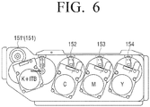
- FIGS. 6 and 7 are diagrams illustrating an operation of controlling a motor in the image forming apparatus 100 according to an exemplary embodiment of the present general inventive concept.
- the image forming apparatus 100 according to the exemplary embodiment drives a photosensitive medium and an image forming medium using a single motor.
- the image forming apparatus 100 includes a plurality of photosensitive media 141, 142, 143, and 144, an intermediate transfer belt 145, a plurality of motors 151(151'), 152, 153, and 154, and four home position sensors 121, 122, 123, and 124 configured to sense a home position of each of the photosensitive media 141, 142, 143, and 144.
- the engine 140 forms a pattern (P) to detect a color dislocation on each of the photosensitive media 141, 142, 143, and 144 through a laser scanning unit thereof, and transfers sub-patterns of the pattern (P) formed on the photosensitive media 141, 142, 143, and 144 on the intermediate transfer belt 145.
- Such an operation of the engine 140 is performed by control of the motor controller 200 with respect to the plurality of motors, and the detailed description related to the operation of forming the pattern P will be described below with reference to FIGS. 10 to 13 .
- the pattern P may include the sub-patterns corresponding to the respective photosensitive media 141, 142, 143, and 144.
- the pattern P is divided into four sections each having the sub-patterns to correspond to each of the photosensitive media 141, 142, 143, and 144. It is possible that the pattern P may be formed to correspond to each of the photosensitive media 141, 142, 143, and 144.
- the home position sensors 121, 122, 123, and 124 may include optical sensors, and sense a home position of each of the photosensitive media 141, 142, 143, and 144 by sensing a location of a projection to detect a home position, which is disposed on a side of a driving gear connected to each of the photosensitive media 141, 142, 143, and 144.
- the motor controller 200 irradiates an infrared ray into the sub-patterns which are transferred on the intermediate transfer belt 145 for each of the photosensitive media 141, 142, 143, and 144, and senses a strength of a reflected light which is reflected from an area of the sub-pattern and a non-pattern area disposed between the adjacent sub-patterns.
- the motor controller 200 senses the sub-patterns which are transferred on the intermediate transfer belt 145 for each of the photosensitive media 141, 142, 143, and 144, and checks a gap variation of the sub-patterns, which represents a periodic velocity variation of the photosensitive media 141, 142, 143, and 144.
- the motor controller 200 may synchronize phases of the respective photosensitive media according to the checked gap variation, control the K motor 151 to drive the K photosensitive medium 141 at a constant velocity, and control the velocities of the C motor 152, the M motor 153, and the Y motor 154 so that the other photosensitive media 142, 143, and 144 follow the linear velocity of the K photosensitive medium.
- the intermediate transfer belt 145 is driven together by the K motor 151, and thus, the velocity of the intermediate transfer belt 145 is the same as the linear velocity of the K photosensitive medium.
- the motor controller 200 may control the velocity of the motor 151 (151') so that the intermediate transfer belt 145 follows the velocity of the K photosensitive medium 141.
- the image forming apparatus may drive five objects to be driven by using four motors so that the linear velocities of the objects are not changed.
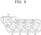
- FIGS. 8 and 9 are diagrams illustrating an operation of controlling a motor in the image forming apparatus 100 according to an exemplary embodiment of the present general inventive concept.
- the image forming apparatus 100 according to the exemplary embodiment drives a photosensitive medium and an image forming medium independently.
- the image forming apparatus 100 includes the plurality of photosensitive media 141, 142, 143, and 144, the intermediate transfer belt 145, the plurality of motors 151, 152, 153, 154, and 155, and the five home position sensors 121, 122, 123, 124, and 125 configured to sense a home position of each of the photosensitive media 141, 142, 143, and 144 and the intermediate transfer belt 145.
- the engine 140 forms the pattern P usable to detect a color dislocation on each of the photosensitive media 141, 142, 143, and 144 through the laser scanning unit thereof, and transfers the sub-patterns of the pattern P formed on the photosensitive media 141, 142, 143, and 144 on the intermediate transfer belt 145.
- Such an operation of the engine 140 is performed by control of the motor controller 200 with respect to the plurality of motors 151, 152, 153, 154, and 155, and the detailed description related to the operation of forming a pattern will be described below with reference to FIGS. 10 to 13 .
- the home position sensors 121, 122, 123, 124, and 125 may include optical sensors, and sense a home position of each of the photosensitive media 141, 142, 143, and 144 and the intermediate transfer belt 145 by sensing a location of a projection to detect a home position which is disposed on a side of a driving gear connected to each of the photosensitive media 141, 142, 143, and 144 and the intermediate transfer belt 145.
- the motor controller 200 irradiates an infrared ray into the sub-patterns which are transferred on the intermediate transfer belt 145 for each of the photosensitive media 141, 142, 143, and 144 by using a Color Toner Density (CTD) sensor, and senses a strength of a reflected light which is reflected from an area of the sub-pattern and a non-pattern area disposed between the adjacent sub-patterns.
- CCD Color Toner Density
- the motor controller 200 senses the sub-patterns which are transferred on the intermediate transfer belt 145 for each of the photosensitive media 141, 142, 143, and 144, and checks a gap variation of the sub-patterns, which can represent a periodic velocity variation of the photosensitive media 141, 142, 143, and 144.
- the motor controller 200 may synchronize phases of each of the photosensitive media according to the checked gap variation, control the K motor 151 to drive the K photosensitive medium 141 at a constant velocity, and control the velocities of the C motor 152, the M motor 153, and the Y motor 154 and the intermediate transfer belt motor 155 so that the other photosensitive media 142, 143, and 144 and the intermediate transfer belt 145 follow the linear velocity of the K photosensitive medium 141.
- the intermediate transfer belt 145 is driven independently from the K motor 151, and thus, the velocity of the intermediate transfer belt 145 is controlled by the linear velocity of the K photosensitive medium 141.
- the image forming apparatus 100 may drive five objects to be driven by using five motors so that the linear velocities of the objects are not changed.
- the image forming apparatus illustrated in FIGS. 6 and 7 according to the exemplary embodiment may include fewer motors than the image forming apparatus illustrated in FIG. 8 and 9 according to the exemplary embodiment, which may reduce the costs and increase the degree of the freedom in design.
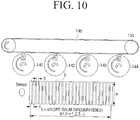
- FIG. 10 is a diagram illustrating a pattern P usable to sense a position change due to a velocity variation of a photosensitive medium
- FIG. 11 is a diagram illustrating a method of outputting the pattern P.
- the pattern P which is transferred on the intermediate transfer belt 145 in order to determine a gap variation which occurs due to the velocity variation of a photosensitive medium may include sub-patterns, for example, a plurality of bar-shaped patterns P1 to P25.
- the bar-shaped patterns P1 to P25 are configured to have a same thickness h and a gap ⁇ of a same distance between centers of the adjacent sub-patterns or a space S between the adjacent sub-patterns.
- the pattern P may have a length L corresponding to an integer ratio of a circumference length of a photosensitive medium, which is effective in stable data acquisition and increase of an error fitting accuracy.
- the sub-patterns are repeatedly outputted by the number of times of a, in an order of Y, M, C, and K.
- the engine 140 forms a black pattern K, a magenta pattern M, a cyan pattern C, and a yellow pattern Y on each of the photosensitive media 141, 142, 143, and 144, and transfers the formed sub-patterns on the intermediate transfer belt 145.
- the engine 140 transfers the pattern P on the intermediate transfer belt 145 one or more times with respect to each of the photosensitive media 141, 142, 143, and 144, which is to detect data more accurately and remove an unexpected measurement value.
- the engine 140 forms the sub-patterns on the respective photosensitive media 141, 142, 143, and 144 at the same time based on the home position of the photosensitive media 141, 142, 143, and 144.
- the controller 160 determines a gap variation function by fitting a gap variation due to a periodic linear velocity variation of the photosensitive media 141, 142, 143, and 144 as a sine function, for example, obtains a velocity function of each motor by using the gap variation function, and allows the other motors 152, 153, and 154 to estimate a velocity of the one motor 151.
- the above described operation of the controller 160 may restrict (reduce) the velocity variation of the photosensitive media 141, 142, 143, and 144, thereby significantly reducing the color dislocation.
- FIG. 12 is a graph illustrating a distance between sub-patterns of FIG. 10 and FIG. 13 is a graph illustrating an operation of fitting the distance between sub-patterns of FIG. 12 .
- a gap difference ⁇ d is obtained by subtracting an original pattern distance (or a reference pattern distance) from a sensed pattern distance.
- the gap difference ⁇ d is a distance between the bar-shaped patterns and is fitted by using a sine function of Asin( ⁇ x/V0 + ⁇ ).
- An optimal fitting may be obtained by finding A and ⁇ which make a sum of squared errors where the gap difference ⁇ d and a difference of Asin( ⁇ x/V0 + ⁇ ) respectively calculated based on each sensed data are raised to second power be minimized from each of given ranges of 0 ⁇ A ⁇ [(Max( ⁇ d)-Min( ⁇ d))/2] and 0 ⁇ 2 ⁇ , as illustrated in FIG.13 .
- the gap variation which is obtained from the pattern P to detect a color dislocation represents a periodic variation form, and thus, may be expressed as a sine function of Asin( ⁇ t+ ⁇ ).
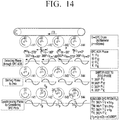
- FIG. 14 is a diagram illustrating a method of controlling a phase synchronization of a photosensitive medium.
- a pattern is outputted based on a home position of a photosensitive medium.
- the photosensitive media 141, 142, 143, and 144 are driven at a constant velocity without controlling a motor.
- the photosensitive media may be an organic photoconductor (OPC)
- phase of the respective photosensitive media 141, 142, 143, and 144 are detected.
- the photosensitive medium where the ACR operation is finished is rotated by the following angle and stopped based on the home position.
- p refers to a pitch of a photosensitive medium.
- each photosensitive medium is rotated by the following angle and stopped based on the home position, considering the sequential operating time.
- ⁇ t t ⁇ / ( ⁇ D/V0) ⁇ 360°
- V0 refers to a processing velocity
- V0 ⁇ Dxf
- f refers to a rotational frequency of a photosensitive medium.
- the phases of the photosensitive media are detected through the ACR operation on the OPC, and then the phases of the photosensitive media may be shifted to zero, for example, a common phase or a same phase.
- the phases of the photosensitive media may be synchronized by considering a pitch of each photosensitive medium.
- FIG. 15 is a diagram illustrating a feed-forward control with respect to a velocity of a photosensitive medium.
- the feed-forward control is performed with respect to the velocity variation of the photosensitive medium for each color, which is recognized as the above described auto color registration (ACR) pattern of the photosensitive medium.
- ACR auto color registration
- An amount and phase of an AC element in the photosensitive medium are detected based on a result of the velocity variation of each photosensitive medium.
- Motor input V MT + A MT Tsin ⁇ t + ⁇ MT
- V MT refers to a reference velocity of a motor
- A refers to AC elements (A Y , A M , A C , A K ) which are measured with respect to the photosensitive medium
- ⁇ refers to phases ( ⁇ Y , ⁇ M , ⁇ C , ⁇ K ) which are measured with respect to the photosensitive medium (deg)
- ⁇ d refers to a time delay phase
- D refers to a diameter of the photosensitive medium
- f refers to a rotational frequency (Hz).
- a control cycle of a motor corresponds to a period of a single rotation of the photosensitive medium. That is, a time t is reset as zero '0' based on Rib every time the photosensitive medium rotates once since an accumulated error may occur after a few times of rotation is performed when the time t is not reset.
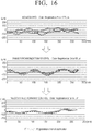
- FIG. 16 is a diagram illustrating an experiment example of a method of controlling a velocity according to an exemplary embodiment of the present general inventive concept.
- An upper graph of FIG. 16 illustrates a registration error of each color when the velocity control is not performed
- a middle graph of FIG. 16 illustrates a registration error of each color when only a phase synchronization control is performed
- a lower graph of FIG. 16 illustrates a registration error of each color when the velocity control according to an exemplary embodiment is performed.
- FIG. 16 illustrates that a case when the control is performed has an improvement of approximately three times, that is, 76 ⁇ m as compared with a case when the control is not performed (Difference of registration errors is 123 ⁇ m).
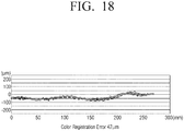
- FIG. 17 is a diagram illustrating a registration error according to a conventional controlling method
- FIG. 18 is a diagram illustrating a registration error according to an exemplary embodiment of the present general inventive concept.
- FIGS. 17 and 18 illustrate that the method of controlling a motor according to the present exemplary embodiment generates fewer registration errors between colors than the conventional method.
- FIG.19 is a flowchart illustrating a method of controlling a motor according to an exemplary embodiment of the present general inventive concept.
- control command with respect to a plurality of photosensitive media is received at operation S1910.
- the control command may include a control command to perform functions corresponding to rotation start/stop, acceleration/reduction of velocity, a velocity reference value with reference to the plurality of motors, etc.
- a periodic velocity of each of the plurality of motors which drives each of the plurality of photosensitive media is received at operation S1920.
- a pattern formed on an intermediate transfer belt is sensed, a gap variation of each of the plurality of photosensitive media is sensed, and thus, a velocity in a form of a sine function corresponding to the checked gap variation may be calculated.
- the plurality of motors are driven according to the sensed velocity at operation S1930.
- One of the plurality of motors is driven at a constant velocity, and the other motors are driven based on a periodic velocity of the one motor which is driven at a constant velocity by feedback-controlling the phases and velocities of the other motors. That is, the plurality of motors may be driven so that the C photosensitive medium, the M photosensitive medium, and the Y photosensitive medium follow the phase and linear velocity of the K photosensitive medium.
- the method of controlling a motor may reduce a linear velocity variation of the motors by allowing the other motors to follow a velocity of a predetermined one motor rather than allowing all of the plurality of motors to follow an ideal velocity, which may reduce the color registration error.
- the method may not require an operation of controlling each motor, thereby improving the degree of freedom in design.
- the method of controlling a motor as illustrated in FIG. 19 may be executed on the image forming apparatus 100 having the configuration of FIG. 1 or the motor controller having the configuration of FIG. 2 , and may be executed on an image forming apparatus or motor controller having other configuration.
- a velocity is applied to one of the plurality of motors to drive one of photosensitive media and a periodic velocity of the one of the plurality of motors can be applied or used to control the other ones of the plurality of motors to drive the other ones of the photosensitive media.
- the periodic velocity may be a velocity generated or detected from the one motor.
- the periodic velocity may be a velocity output from the one motor which is used to synchronize phases of the motors.
- the periodic velocity may be a velocity corresponding to a periodic form, for example, a sine wave form.
- the motor controller 200 when the other ones of the plurality of motors 150 are controlled according to the periodic velocity, the motor controller 200 generates a velocity to be applied to the one motor of the plurality of motors 150 and also generates a periodic velocity to be applied to the other motors of the plurality of motors 150. In this case, the motor controller 200 may control the one motor with the velocity and the other motors with the periodic velocity. It is possible that when the one motor of the plurality of motors 150 receives a velocity from the motor controller 200, the one motor may generate the periodic velocity to be applied to the other motors. In this case, the periodic velocity may be directly output from the one motor to the other motors.
- the motor controller 200 may store information or data on the velocity to be applied to the one motor and/or the periodic velocity to be applied to all of the other motors in a memory thereof.
- the memory may be included in the motor controller 200, in the controller 160, in at least one of the motors 150, or in the storage 130 according to a user or design preference.
- one of motors can be usable to control the other ones of the motors in an image forming apparatus.
- embodiments of the present general inventive concept are not limited thereto. It is possible that two of the motors can be controlled according to a corresponding velocity and/or phase and then one of the two motors can be useable to control the other ones of the motors.
- the one of the two motors may be a motor to drive one of the photosensitive media or an intermediate transfer belt. It is also possible that only one motor is controlled according to at least one of remaining motors which are controlled according to a corresponding velocity and/or phase. In this case, the only one motor may be a motor to drive an intermediate transfer belt, one of the photosensitive media, or other components of the image forming apparatus.
- the aforementioned method may be embodied as a program (or application) including an algorithm which is executable on a computer, and the program may be stored and provided in a non-transitory computer readable medium.
- the non-transitory recordable medium refers to a medium which may store data semi-permanently rather than storing data for a short time such as a register, a cache, and a memory and may be readable by an apparatus.
- the above-described various applications and programs may be stored in the non- transitory recordable medium like a compact disc (CD), a digital versatile disk (DVD), a hard disk, a Blu-ray disk, a universal serial bus (USB), a memory card, and a read-only memory (ROM), etc., and provided therein.
- an image forming apparatus comprising, inter alia , an image forming unit configured to perform a printing operation by using a plurality of photosensitive media; a plurality of motors configured to drive the plurality of photosensitive media; and a motor controller configured to control based on a periodic velocity of one motor from among the plurality of motors a phase and a velocity of the other of the plurality of motors based on a periodic velocity of one motor from among the plurality of motors.
- the plurality of photosensitive media are a K photosensitive medium, a C photosensitive medium, an M photosensitive medium, and a Y photosensitive medium
- the plurality of motors are a K motor which drives the K photosensitive medium, a C motor which drives the C photosensitive medium, an M motor which drives the M photosensitive medium, and a Y motor which drives the Y photosensitive medium
- the motor controller is arranged to controls a velocity of the C motor, the M motor, and the Y motor based on a velocity (e.g. the periodic velocity) of the K motor.
Landscapes
- Physics & Mathematics (AREA)
- General Physics & Mathematics (AREA)
- Engineering & Computer Science (AREA)
- Microelectronics & Electronic Packaging (AREA)
- Control Or Security For Electrophotography (AREA)
- Color Electrophotography (AREA)
Claims (10)
- Bilderzeugungsvorrichtung (100), Folgendes umfassend:mehrere lichtempfindliche Medien (141, 142, 143, 144);eine Bilderzeugungseinheit, die konfiguriert ist, um einen Druckvorgang unter Verwendung der mehreren lichtempfindlichen Medien durchzuführen;mehrere Motoren (151, 152, 153, 154), die konfiguriert sind, um die mehreren lichtempfindlichen Medien anzutreiben; undeine Motorsteuerung (200), die konfiguriert ist, um basierend auf einer periodischen Geschwindigkeit eines Motors der mehreren Motoren eine Phase und eine Geschwindigkeit der anderen Motoren zu steuern, wobei die Motorsteuerung angeordnet ist, um periodische Geschwindigkeiten der mehreren Motoren zu erfassen, um eine Geschwindigkeitsphase jedes der mehreren Motoren basierend auf den erfassten periodischen Geschwindigkeiten zu synchronisieren, und um die anderen Motoren vorwärtszusteuern, um basierend auf der periodischen Geschwindigkeit des einen Motors der mehreren Motoren, deren Geschwindigkeitsphasen synchronisiert sind, eine gleiche Geschwindigkeit aufzuweisen; undwobei die Bilderzeugungseinheit angeordnet ist, um ein voreingestelltes Muster auf einem Bilderzeugungsmedium (145) unter Verwendung jedes der mehreren lichtempfindlichen Medien auszubilden; undwobei die Motorsteuerung angeordnet ist, um eine periodische Geschwindigkeit jedes der mehreren lichtempfindlichen Medien zu erfassen, indem sie das auf dem Bilderzeugungsmedium ausgebildete Muster erfasst; undwobei die Motorsteuerung angeordnet ist, um das auf dem Bilderzeugungsmedium ausgebildete Muster zu erfassen, indem sie eine Lückenvariation jedes der mehreren lichtempfindlichen Medien durch das Erfassen des auf dem Bilderzeugungsmedium ausgebildeten Musters prüft, und die periodische Geschwindigkeit in Form einer Sinusfunktion zu berechnen, die der Lückenvariation entspricht, wobei die Motorsteuerung angeordnet ist, um die anderen Motoren derart zu steuern, dass sie einer Sinusfunktion des einen Motors folgen.
- Vorrichtung nach Anspruch 1, wobei:die mehreren lichtempfindlichen Medien ein lichtempfindliches K-Medium, ein lichtempfindliches C-Medium, ein lichtempfindliches M-Medium und ein lichtempfindliches Y-Medium sind;die mehreren Motoren ein K-Motor, der das lichtempfindliche K-Medium antreibt, ein C-Motor, der das lichtempfindliche C-Medium antreibt, ein M-Motor, der das lichtempfindliche M-Medium antreibt, und ein Y-Motor, der das lichtempfindliche Y-Medium antreibt, sind; und die Motorsteuerung angeordnet ist, um eine Geschwindigkeit des C-Motors, des M-Motors und des Y-Motors basierend auf einer Geschwindigkeit des K-Motors zu steuern.
- Vorrichtung nach Anspruch 2, wobei der K-Motor angeordnet ist, um ein Bilderzeugungsmedium (145) zusammen mit dem lichtempfindlichen K-Medium anzutreiben.
- Vorrichtung nach Anspruch 1, wobei die Motorsteuerung angeordnet ist, um eine Ausgangsposition jedes der mehreren lichtempfindlichen Medien zu erfassen und eine Stoppposition jedes der mehreren lichtempfindlichen Medien basierend auf den erfassten periodischen Geschwindigkeiten und der Ausgangsposition zu bestimmen.
- Vorrichtung nach einem der Ansprüche 1 bis 4, wobei die Motorsteuerung angeordnet ist, um den einen Motor mit einer konstanten Geschwindigkeit anzutreiben.
- Vorrichtung nach einem der Ansprüche 1 bis 5, wobei die Motorsteuerung angeordnet ist, um eine Geschwindigkeit der anderen Motoren derart zu steuern, dass sie einem Zeitraum einer einzelnen Drehung eines lichtempfindlichen Mediums entspricht.
- Verfahren zum Steuern mehrerer Motoren (151, 152, 153, 154), die an einer Bilderzeugungsvorrichtung montiert sind,
wobei das Verfahren Folgendes umfasst:Empfangen eines Steuerbefehls bezüglich mehrerer lichtempfindlicher Medien (141, 142, 143, 144);Ausbilden eines voreingestellten Musters auf einem Bilderzeugungsmedium (145) unter Verwendung jedes der mehreren lichtempfindlichen Medien;Erfassen einer periodischen Geschwindigkeit jedes von mehreren Motoren, die jedes der mehreren lichtempfindlichen Medien antreiben;Antreiben eines Motors der mehreren Motoren mit einer konstanten Geschwindigkeit; und Vorwärtssteuern und Antreiben einer Phase und einer Geschwindigkeit der anderen Motoren basierend auf der periodischen Geschwindigkeit des einen Motors, der mit einer konstanten Geschwindigkeit angetrieben wird; und Synchronisieren einer Geschwindigkeitsphase jedes der mehreren Motoren basierend auf der erfassten periodischen Geschwindigkeit;wobei das Vorwärtssteuern und Antreiben ein Vorwärtssteuern der anderen Motoren dahin gehend umfasst, eine gleiche Geschwindigkeit basierend auf der periodischen Geschwindigkeit des einen Motors der mehreren Motoren aufzuweisen, deren Geschwindigkeitsphasen synchronisiert sind,wobei das Erfassen der periodischen Geschwindigkeit das Ausbilden eines voreingestellten Musters auf einem Bilderzeugungsmedium unter Verwendung jedes der mehreren lichtempfindlichen Medien und das Erfassen einer periodischen Geschwindigkeit jedes der mehreren lichtempfindlichen Medien durch das Erfassen des auf dem Bilderzeugungsmedium ausgebildeten Musters umfasst,wobei das Erfassen der periodischen Geschwindigkeit das Prüfen einer Lückenvariation jedes der mehreren lichtempfindlichen Medien durch das Erfassen des auf dem Bilderzeugungsmedium ausgebildeten Musters und das Berechnen einer Geschwindigkeit in Form einer Sinusfunktion, die der Lückenvariation entspricht, umfasst,wobei das Vorwärtssteuern und Antreiben das Steuern der anderen Motoren dahin gehend umfasst, dass sie einer Sinusfunktion des einen Motors folgen. - Verfahren nach Anspruch 7, wobei:die mehreren lichtempfindlichen Medien ein lichtempfindliches K-Medium, ein lichtempfindliches C-Medium, ein lichtempfindliches M-Medium und ein lichtempfindliches Y-Medium sind;die mehreren Motoren ein K-Motor, der das lichtempfindliche K-Medium antreibt, ein C-Motor, der das lichtempfindliche C-Medium antreibt, ein M-Motor, der das lichtempfindliche M-Medium antreibt, und ein Y-Motor, der das lichtempfindliche Y-Medium antreibt, sind; und das Vorwärtssteuern und Antreiben das Steuern einer Geschwindigkeit des C-Motors, des M-Motors und des Y-Motors basierend auf der Geschwindigkeit des K-Motors umfasst.
- Verfahren nach Anspruch 8, wobei der K-Motor zusammen mit dem lichtempfindlichen K-Medium ein Bilderzeugungsmedium antreibt.
- Verfahren nach einem der Ansprüche 7 bis 9, wobei das Vorwärtssteuern und Antreiben das Steuern einer Geschwindigkeit der anderen Motoren dahin gehend umfasst, einem Zeitraum einer einzelnen Drehung eines lichtempfindlichen Mediums zu entsprechen.
Applications Claiming Priority (1)
| Application Number | Priority Date | Filing Date | Title |
|---|---|---|---|
| KR1020130161067A KR20150073407A (ko) | 2013-12-23 | 2013-12-23 | 화상형성장치 및 모터 제어 방법 |
Publications (2)
| Publication Number | Publication Date |
|---|---|
| EP2887145A1 EP2887145A1 (de) | 2015-06-24 |
| EP2887145B1 true EP2887145B1 (de) | 2019-06-12 |
Family
ID=51298554
Family Applications (1)
| Application Number | Title | Priority Date | Filing Date |
|---|---|---|---|
| EP14179392.7A Not-in-force EP2887145B1 (de) | 2013-12-23 | 2014-07-31 | Bilderzeugungsvorrichtung und Motorsteuerungsverfahren |
Country Status (5)
| Country | Link |
|---|---|
| US (1) | US9229414B2 (de) |
| EP (1) | EP2887145B1 (de) |
| KR (1) | KR20150073407A (de) |
| CN (1) | CN104730874B (de) |
| WO (1) | WO2015099252A1 (de) |
Families Citing this family (1)
| Publication number | Priority date | Publication date | Assignee | Title |
|---|---|---|---|---|
| JP2019008217A (ja) * | 2017-06-27 | 2019-01-17 | コニカミノルタ株式会社 | 画像形成装置、画像形成システム、画像形成方法、および画像形成装置用プログラム |
Family Cites Families (15)
| Publication number | Priority date | Publication date | Assignee | Title |
|---|---|---|---|---|
| JP3932715B2 (ja) | 1999-03-02 | 2007-06-20 | 松下電器産業株式会社 | カラー画像形成装置 |
| JP2001022147A (ja) | 1999-07-09 | 2001-01-26 | Canon Inc | 多色画像形成装置 |
| JP4058265B2 (ja) * | 2001-12-11 | 2008-03-05 | キヤノン株式会社 | カラー画像形成装置及びその制御方法 |
| US7379680B2 (en) | 2005-05-10 | 2008-05-27 | Xerox Corporation | Systems and methods for determining feed forward correction profile for mechanical disturbances in image forming devices |
| JP4947772B2 (ja) * | 2005-11-15 | 2012-06-06 | 株式会社リコー | 画像形成装置 |
| JP4264442B2 (ja) | 2006-04-14 | 2009-05-20 | シャープ株式会社 | 色ずれの調整方法および画像形成装置 |
| JP4961296B2 (ja) * | 2007-08-02 | 2012-06-27 | キヤノン株式会社 | 画像形成装置 |
| JP5288247B2 (ja) * | 2008-06-24 | 2013-09-11 | 株式会社リコー | 画像形成装置及び画像形成方法 |
| JP5263674B2 (ja) * | 2009-01-19 | 2013-08-14 | 株式会社リコー | 画像形成装置 |
| JP5262809B2 (ja) | 2009-02-18 | 2013-08-14 | コニカミノルタビジネステクノロジーズ株式会社 | 画像形成装置 |
| JP5369855B2 (ja) | 2009-04-20 | 2013-12-18 | コニカミノルタ株式会社 | 画像形成装置 |
| KR101639239B1 (ko) | 2009-10-28 | 2016-07-13 | 삼성전자주식회사 | 화상형성장치 및 그 제어방법 |
| JP2012018247A (ja) | 2010-07-07 | 2012-01-26 | Canon Inc | 画像形成装置及びその制御方法 |
| JP5725761B2 (ja) | 2010-08-20 | 2015-05-27 | キヤノン株式会社 | 画像形成装置 |
| JP5793954B2 (ja) | 2011-05-18 | 2015-10-14 | 株式会社リコー | 画像形成装置 |
-
2013
- 2013-12-23 KR KR1020130161067A patent/KR20150073407A/ko not_active Withdrawn
-
2014
- 2014-06-11 US US14/301,386 patent/US9229414B2/en active Active
- 2014-06-25 WO PCT/KR2014/005655 patent/WO2015099252A1/en not_active Ceased
- 2014-07-31 EP EP14179392.7A patent/EP2887145B1/de not_active Not-in-force
- 2014-09-12 CN CN201410462903.1A patent/CN104730874B/zh not_active Expired - Fee Related
Non-Patent Citations (1)
| Title |
|---|
| None * |
Also Published As
| Publication number | Publication date |
|---|---|
| EP2887145A1 (de) | 2015-06-24 |
| KR20150073407A (ko) | 2015-07-01 |
| CN104730874A (zh) | 2015-06-24 |
| US9229414B2 (en) | 2016-01-05 |
| WO2015099252A1 (en) | 2015-07-02 |
| US20150177672A1 (en) | 2015-06-25 |
| CN104730874B (zh) | 2018-11-16 |
Similar Documents
| Publication | Publication Date | Title |
|---|---|---|
| US6760559B2 (en) | Image-formation apparatus, controlling method thereof and image-formation method | |
| JP5003420B2 (ja) | 画像形成装置 | |
| US7929891B2 (en) | Alignment error correcting unit for image forming apparatus | |
| US9366984B2 (en) | Image forming apparatus that forms color image by superimposing plurality of images in different colors | |
| JP2014178571A (ja) | 画像形成装置 | |
| EP2743779A2 (de) | Bilderzeugungsvorrichtung zur Verhinderung der Erzeugung von Oberflächengeschwindigkeitsunterschieden zwischen lichtempfindlicher Trommel und Zwischenübertragungsband | |
| EP2887145B1 (de) | Bilderzeugungsvorrichtung und Motorsteuerungsverfahren | |
| EP2746858A2 (de) | Bilderzeugungsvorrichtung mit Unterdrückung des Auftretens von Farbverschiebung in Bildern und Verfahren zur Steuerung davon | |
| US9229401B2 (en) | Image forming apparatus | |
| EP2495617A2 (de) | Bilderzeugungsvorrichtung und Verfahren für die Farbregistrierungsberichtigung | |
| JP5369445B2 (ja) | モータ制御装置と画像形成装置とプログラム | |
| US20140169812A1 (en) | Image forming apparatus | |
| KR20140105253A (ko) | 화상형성장치 및 화상형성방법 | |
| US9086666B2 (en) | Image forming apparatus having a control unit that controls an image bearing member | |
| US20160004204A1 (en) | Image forming apparatus and method | |
| JP2015040999A (ja) | 画像形成装置 | |
| JP4958205B2 (ja) | 回転装置,感光体ドラム回転装置および画像形成装置 | |
| JP4921902B2 (ja) | 回転体駆動制御装置、回転体駆動制御方法、プログラム、および画像形成装置 | |
| JP2020132391A (ja) | 用紙厚さ検出装置及びこれを用いた画像形成装置 | |
| JP2014119596A (ja) | 画像形成装置 | |
| JP4782399B2 (ja) | 像担持体駆動方法 | |
| JP5728237B2 (ja) | 画像形成装置 | |
| JP2007062223A (ja) | 画像形成装置及びその制御方法 | |
| CN117192921A (zh) | 一种图像形成装置、感光部件的相位配准方法 | |
| JP5003432B2 (ja) | 画像形成装置および画像形成システム |
Legal Events
| Date | Code | Title | Description |
|---|---|---|---|
| PUAI | Public reference made under article 153(3) epc to a published international application that has entered the european phase |
Free format text: ORIGINAL CODE: 0009012 |
|
| 17P | Request for examination filed |
Effective date: 20140731 |
|
| AK | Designated contracting states |
Kind code of ref document: A1 Designated state(s): AL AT BE BG CH CY CZ DE DK EE ES FI FR GB GR HR HU IE IS IT LI LT LU LV MC MK MT NL NO PL PT RO RS SE SI SK SM TR |
|
| AX | Request for extension of the european patent |
Extension state: BA ME |
|
| R17P | Request for examination filed (corrected) |
Effective date: 20160104 |
|
| RBV | Designated contracting states (corrected) |
Designated state(s): AL AT BE BG CH CY CZ DE DK EE ES FI FR GB GR HR HU IE IS IT LI LT LU LV MC MK MT NL NO PL PT RO RS SE SI SK SM TR |
|
| RAP1 | Party data changed (applicant data changed or rights of an application transferred) |
Owner name: S-PRINTING SOLUTION CO., LTD. |
|
| RAP1 | Party data changed (applicant data changed or rights of an application transferred) |
Owner name: HP PRINTING KOREA CO., LTD. |
|
| GRAP | Despatch of communication of intention to grant a patent |
Free format text: ORIGINAL CODE: EPIDOSNIGR1 |
|
| STAA | Information on the status of an ep patent application or granted ep patent |
Free format text: STATUS: GRANT OF PATENT IS INTENDED |
|
| INTG | Intention to grant announced |
Effective date: 20190228 |
|
| GRAS | Grant fee paid |
Free format text: ORIGINAL CODE: EPIDOSNIGR3 |
|
| GRAA | (expected) grant |
Free format text: ORIGINAL CODE: 0009210 |
|
| STAA | Information on the status of an ep patent application or granted ep patent |
Free format text: STATUS: THE PATENT HAS BEEN GRANTED |
|
| AK | Designated contracting states |
Kind code of ref document: B1 Designated state(s): AL AT BE BG CH CY CZ DE DK EE ES FI FR GB GR HR HU IE IS IT LI LT LU LV MC MK MT NL NO PL PT RO RS SE SI SK SM TR |
|
| REG | Reference to a national code |
Ref country code: GB Ref legal event code: FG4D |
|
| REG | Reference to a national code |
Ref country code: CH Ref legal event code: EP |
|
| REG | Reference to a national code |
Ref country code: AT Ref legal event code: REF Ref document number: 1143347 Country of ref document: AT Kind code of ref document: T Effective date: 20190615 |
|
| REG | Reference to a national code |
Ref country code: DE Ref legal event code: R096 Ref document number: 602014048089 Country of ref document: DE |
|
| REG | Reference to a national code |
Ref country code: IE Ref legal event code: FG4D |
|
| REG | Reference to a national code |
Ref country code: NL Ref legal event code: MP Effective date: 20190612 |
|
| REG | Reference to a national code |
Ref country code: LT Ref legal event code: MG4D |
|
| PG25 | Lapsed in a contracting state [announced via postgrant information from national office to epo] |
Ref country code: HR Free format text: LAPSE BECAUSE OF FAILURE TO SUBMIT A TRANSLATION OF THE DESCRIPTION OR TO PAY THE FEE WITHIN THE PRESCRIBED TIME-LIMIT Effective date: 20190612 Ref country code: LT Free format text: LAPSE BECAUSE OF FAILURE TO SUBMIT A TRANSLATION OF THE DESCRIPTION OR TO PAY THE FEE WITHIN THE PRESCRIBED TIME-LIMIT Effective date: 20190612 Ref country code: FI Free format text: LAPSE BECAUSE OF FAILURE TO SUBMIT A TRANSLATION OF THE DESCRIPTION OR TO PAY THE FEE WITHIN THE PRESCRIBED TIME-LIMIT Effective date: 20190612 Ref country code: NO Free format text: LAPSE BECAUSE OF FAILURE TO SUBMIT A TRANSLATION OF THE DESCRIPTION OR TO PAY THE FEE WITHIN THE PRESCRIBED TIME-LIMIT Effective date: 20190912 Ref country code: SE Free format text: LAPSE BECAUSE OF FAILURE TO SUBMIT A TRANSLATION OF THE DESCRIPTION OR TO PAY THE FEE WITHIN THE PRESCRIBED TIME-LIMIT Effective date: 20190612 Ref country code: AL Free format text: LAPSE BECAUSE OF FAILURE TO SUBMIT A TRANSLATION OF THE DESCRIPTION OR TO PAY THE FEE WITHIN THE PRESCRIBED TIME-LIMIT Effective date: 20190612 |
|
| PG25 | Lapsed in a contracting state [announced via postgrant information from national office to epo] |
Ref country code: BG Free format text: LAPSE BECAUSE OF FAILURE TO SUBMIT A TRANSLATION OF THE DESCRIPTION OR TO PAY THE FEE WITHIN THE PRESCRIBED TIME-LIMIT Effective date: 20190912 Ref country code: GR Free format text: LAPSE BECAUSE OF FAILURE TO SUBMIT A TRANSLATION OF THE DESCRIPTION OR TO PAY THE FEE WITHIN THE PRESCRIBED TIME-LIMIT Effective date: 20190913 Ref country code: LV Free format text: LAPSE BECAUSE OF FAILURE TO SUBMIT A TRANSLATION OF THE DESCRIPTION OR TO PAY THE FEE WITHIN THE PRESCRIBED TIME-LIMIT Effective date: 20190612 Ref country code: RS Free format text: LAPSE BECAUSE OF FAILURE TO SUBMIT A TRANSLATION OF THE DESCRIPTION OR TO PAY THE FEE WITHIN THE PRESCRIBED TIME-LIMIT Effective date: 20190612 |
|
| RAP2 | Party data changed (patent owner data changed or rights of a patent transferred) |
Owner name: HEWLETT-PACKARD DEVELOPMENT COMPANY, L.P. |
|
| REG | Reference to a national code |
Ref country code: DE Ref legal event code: R082 Ref document number: 602014048089 Country of ref document: DE Representative=s name: SCHOPPE, ZIMMERMANN, STOECKELER, ZINKLER, SCHE, DE Ref country code: DE Ref legal event code: R081 Ref document number: 602014048089 Country of ref document: DE Owner name: HEWLETT-PACKARD DEVELOPMENT COMPANY, L.P., SPR, US Free format text: FORMER OWNER: HP PRINTING KOREA CO., LTD., SUWON-SI, GYEONGGI-DO, KR |
|
| REG | Reference to a national code |
Ref country code: AT Ref legal event code: MK05 Ref document number: 1143347 Country of ref document: AT Kind code of ref document: T Effective date: 20190612 |
|
| PG25 | Lapsed in a contracting state [announced via postgrant information from national office to epo] |
Ref country code: EE Free format text: LAPSE BECAUSE OF FAILURE TO SUBMIT A TRANSLATION OF THE DESCRIPTION OR TO PAY THE FEE WITHIN THE PRESCRIBED TIME-LIMIT Effective date: 20190612 Ref country code: NL Free format text: LAPSE BECAUSE OF FAILURE TO SUBMIT A TRANSLATION OF THE DESCRIPTION OR TO PAY THE FEE WITHIN THE PRESCRIBED TIME-LIMIT Effective date: 20190612 Ref country code: SK Free format text: LAPSE BECAUSE OF FAILURE TO SUBMIT A TRANSLATION OF THE DESCRIPTION OR TO PAY THE FEE WITHIN THE PRESCRIBED TIME-LIMIT Effective date: 20190612 Ref country code: PT Free format text: LAPSE BECAUSE OF FAILURE TO SUBMIT A TRANSLATION OF THE DESCRIPTION OR TO PAY THE FEE WITHIN THE PRESCRIBED TIME-LIMIT Effective date: 20191014 Ref country code: CZ Free format text: LAPSE BECAUSE OF FAILURE TO SUBMIT A TRANSLATION OF THE DESCRIPTION OR TO PAY THE FEE WITHIN THE PRESCRIBED TIME-LIMIT Effective date: 20190612 Ref country code: RO Free format text: LAPSE BECAUSE OF FAILURE TO SUBMIT A TRANSLATION OF THE DESCRIPTION OR TO PAY THE FEE WITHIN THE PRESCRIBED TIME-LIMIT Effective date: 20190612 Ref country code: AT Free format text: LAPSE BECAUSE OF FAILURE TO SUBMIT A TRANSLATION OF THE DESCRIPTION OR TO PAY THE FEE WITHIN THE PRESCRIBED TIME-LIMIT Effective date: 20190612 |
|
| PG25 | Lapsed in a contracting state [announced via postgrant information from national office to epo] |
Ref country code: IS Free format text: LAPSE BECAUSE OF FAILURE TO SUBMIT A TRANSLATION OF THE DESCRIPTION OR TO PAY THE FEE WITHIN THE PRESCRIBED TIME-LIMIT Effective date: 20191012 Ref country code: SM Free format text: LAPSE BECAUSE OF FAILURE TO SUBMIT A TRANSLATION OF THE DESCRIPTION OR TO PAY THE FEE WITHIN THE PRESCRIBED TIME-LIMIT Effective date: 20190612 Ref country code: ES Free format text: LAPSE BECAUSE OF FAILURE TO SUBMIT A TRANSLATION OF THE DESCRIPTION OR TO PAY THE FEE WITHIN THE PRESCRIBED TIME-LIMIT Effective date: 20190612 Ref country code: IT Free format text: LAPSE BECAUSE OF FAILURE TO SUBMIT A TRANSLATION OF THE DESCRIPTION OR TO PAY THE FEE WITHIN THE PRESCRIBED TIME-LIMIT Effective date: 20190612 |
|
| REG | Reference to a national code |
Ref country code: CH Ref legal event code: PL |
|
| REG | Reference to a national code |
Ref country code: DE Ref legal event code: R097 Ref document number: 602014048089 Country of ref document: DE |
|
| PG25 | Lapsed in a contracting state [announced via postgrant information from national office to epo] |
Ref country code: MC Free format text: LAPSE BECAUSE OF FAILURE TO SUBMIT A TRANSLATION OF THE DESCRIPTION OR TO PAY THE FEE WITHIN THE PRESCRIBED TIME-LIMIT Effective date: 20190612 Ref country code: TR Free format text: LAPSE BECAUSE OF FAILURE TO SUBMIT A TRANSLATION OF THE DESCRIPTION OR TO PAY THE FEE WITHIN THE PRESCRIBED TIME-LIMIT Effective date: 20190612 |
|
| REG | Reference to a national code |
Ref country code: BE Ref legal event code: MM Effective date: 20190731 |
|
| PLBE | No opposition filed within time limit |
Free format text: ORIGINAL CODE: 0009261 |
|
| STAA | Information on the status of an ep patent application or granted ep patent |
Free format text: STATUS: NO OPPOSITION FILED WITHIN TIME LIMIT |
|
| PG25 | Lapsed in a contracting state [announced via postgrant information from national office to epo] |
Ref country code: DK Free format text: LAPSE BECAUSE OF FAILURE TO SUBMIT A TRANSLATION OF THE DESCRIPTION OR TO PAY THE FEE WITHIN THE PRESCRIBED TIME-LIMIT Effective date: 20190612 Ref country code: PL Free format text: LAPSE BECAUSE OF FAILURE TO SUBMIT A TRANSLATION OF THE DESCRIPTION OR TO PAY THE FEE WITHIN THE PRESCRIBED TIME-LIMIT Effective date: 20190612 |
|
| 26N | No opposition filed |
Effective date: 20200313 |
|
| PG25 | Lapsed in a contracting state [announced via postgrant information from national office to epo] |
Ref country code: LU Free format text: LAPSE BECAUSE OF NON-PAYMENT OF DUE FEES Effective date: 20190731 Ref country code: CH Free format text: LAPSE BECAUSE OF NON-PAYMENT OF DUE FEES Effective date: 20190731 Ref country code: LI Free format text: LAPSE BECAUSE OF NON-PAYMENT OF DUE FEES Effective date: 20190731 Ref country code: SI Free format text: LAPSE BECAUSE OF FAILURE TO SUBMIT A TRANSLATION OF THE DESCRIPTION OR TO PAY THE FEE WITHIN THE PRESCRIBED TIME-LIMIT Effective date: 20190612 Ref country code: BE Free format text: LAPSE BECAUSE OF NON-PAYMENT OF DUE FEES Effective date: 20190731 Ref country code: IS Free format text: LAPSE BECAUSE OF FAILURE TO SUBMIT A TRANSLATION OF THE DESCRIPTION OR TO PAY THE FEE WITHIN THE PRESCRIBED TIME-LIMIT Effective date: 20200224 |
|
| PG2D | Information on lapse in contracting state deleted |
Ref country code: IS |
|
| PG25 | Lapsed in a contracting state [announced via postgrant information from national office to epo] |
Ref country code: IE Free format text: LAPSE BECAUSE OF NON-PAYMENT OF DUE FEES Effective date: 20190731 |
|
| PG25 | Lapsed in a contracting state [announced via postgrant information from national office to epo] |
Ref country code: CY Free format text: LAPSE BECAUSE OF FAILURE TO SUBMIT A TRANSLATION OF THE DESCRIPTION OR TO PAY THE FEE WITHIN THE PRESCRIBED TIME-LIMIT Effective date: 20190612 |
|
| PG25 | Lapsed in a contracting state [announced via postgrant information from national office to epo] |
Ref country code: HU Free format text: LAPSE BECAUSE OF FAILURE TO SUBMIT A TRANSLATION OF THE DESCRIPTION OR TO PAY THE FEE WITHIN THE PRESCRIBED TIME-LIMIT; INVALID AB INITIO Effective date: 20140731 Ref country code: MT Free format text: LAPSE BECAUSE OF FAILURE TO SUBMIT A TRANSLATION OF THE DESCRIPTION OR TO PAY THE FEE WITHIN THE PRESCRIBED TIME-LIMIT Effective date: 20190612 |
|
| PG25 | Lapsed in a contracting state [announced via postgrant information from national office to epo] |
Ref country code: MK Free format text: LAPSE BECAUSE OF FAILURE TO SUBMIT A TRANSLATION OF THE DESCRIPTION OR TO PAY THE FEE WITHIN THE PRESCRIBED TIME-LIMIT Effective date: 20190612 |
|
| PGFP | Annual fee paid to national office [announced via postgrant information from national office to epo] |
Ref country code: FR Payment date: 20230621 Year of fee payment: 10 |
|
| PGFP | Annual fee paid to national office [announced via postgrant information from national office to epo] |
Ref country code: GB Payment date: 20230620 Year of fee payment: 10 |
|
| PGFP | Annual fee paid to national office [announced via postgrant information from national office to epo] |
Ref country code: DE Payment date: 20230620 Year of fee payment: 10 |
|
| REG | Reference to a national code |
Ref country code: DE Ref legal event code: R119 Ref document number: 602014048089 Country of ref document: DE |
|
| GBPC | Gb: european patent ceased through non-payment of renewal fee |
Effective date: 20240731 |
|
| PG25 | Lapsed in a contracting state [announced via postgrant information from national office to epo] |
Ref country code: DE Free format text: LAPSE BECAUSE OF NON-PAYMENT OF DUE FEES Effective date: 20250201 |
|
| PG25 | Lapsed in a contracting state [announced via postgrant information from national office to epo] |
Ref country code: FR Free format text: LAPSE BECAUSE OF NON-PAYMENT OF DUE FEES Effective date: 20240731 |
|
| PG25 | Lapsed in a contracting state [announced via postgrant information from national office to epo] |
Ref country code: GB Free format text: LAPSE BECAUSE OF NON-PAYMENT OF DUE FEES Effective date: 20240731 |