EP2740622B1 - Système de toit pour véhicule - Google Patents
Système de toit pour véhicule Download PDFInfo
- Publication number
- EP2740622B1 EP2740622B1 EP14155790.0A EP14155790A EP2740622B1 EP 2740622 B1 EP2740622 B1 EP 2740622B1 EP 14155790 A EP14155790 A EP 14155790A EP 2740622 B1 EP2740622 B1 EP 2740622B1
- Authority
- EP
- European Patent Office
- Prior art keywords
- guide
- sliding member
- lever
- closure
- roof system
- Prior art date
- Legal status (The legal status is an assumption and is not a legal conclusion. Google has not performed a legal analysis and makes no representation as to the accuracy of the status listed.)
- Active
Links
- 230000007246 mechanism Effects 0.000 claims description 36
- 229910000831 Steel Inorganic materials 0.000 description 3
- 238000007789 sealing Methods 0.000 description 3
- 239000010959 steel Substances 0.000 description 3
- 238000005452 bending Methods 0.000 description 2
- 230000000694 effects Effects 0.000 description 2
- 239000002184 metal Substances 0.000 description 2
- 238000010276 construction Methods 0.000 description 1
- 238000006073 displacement reaction Methods 0.000 description 1
- 238000005538 encapsulation Methods 0.000 description 1
- 238000010137 moulding (plastic) Methods 0.000 description 1
- 230000001105 regulatory effect Effects 0.000 description 1
Images


Classifications
-
- B—PERFORMING OPERATIONS; TRANSPORTING
- B60—VEHICLES IN GENERAL
- B60J—WINDOWS, WINDSCREENS, NON-FIXED ROOFS, DOORS, OR SIMILAR DEVICES FOR VEHICLES; REMOVABLE EXTERNAL PROTECTIVE COVERINGS SPECIALLY ADAPTED FOR VEHICLES
- B60J7/00—Non-fixed roofs; Roofs with movable panels, e.g. rotary sunroofs
- B60J7/02—Non-fixed roofs; Roofs with movable panels, e.g. rotary sunroofs of sliding type, e.g. comprising guide shoes
- B60J7/04—Non-fixed roofs; Roofs with movable panels, e.g. rotary sunroofs of sliding type, e.g. comprising guide shoes with rigid plate-like element or elements, e.g. open roofs with harmonica-type folding rigid panels
- B60J7/043—Sunroofs e.g. sliding above the roof
- B60J7/0435—Sunroofs e.g. sliding above the roof pivoting upwardly to vent mode and moving at the outside of the roof to fully open mode
-
- B—PERFORMING OPERATIONS; TRANSPORTING
- B60—VEHICLES IN GENERAL
- B60J—WINDOWS, WINDSCREENS, NON-FIXED ROOFS, DOORS, OR SIMILAR DEVICES FOR VEHICLES; REMOVABLE EXTERNAL PROTECTIVE COVERINGS SPECIALLY ADAPTED FOR VEHICLES
- B60J7/00—Non-fixed roofs; Roofs with movable panels, e.g. rotary sunroofs
- B60J7/02—Non-fixed roofs; Roofs with movable panels, e.g. rotary sunroofs of sliding type, e.g. comprising guide shoes
- B60J7/04—Non-fixed roofs; Roofs with movable panels, e.g. rotary sunroofs of sliding type, e.g. comprising guide shoes with rigid plate-like element or elements, e.g. open roofs with harmonica-type folding rigid panels
- B60J7/043—Sunroofs e.g. sliding above the roof
-
- B—PERFORMING OPERATIONS; TRANSPORTING
- B60—VEHICLES IN GENERAL
- B60J—WINDOWS, WINDSCREENS, NON-FIXED ROOFS, DOORS, OR SIMILAR DEVICES FOR VEHICLES; REMOVABLE EXTERNAL PROTECTIVE COVERINGS SPECIALLY ADAPTED FOR VEHICLES
- B60J7/00—Non-fixed roofs; Roofs with movable panels, e.g. rotary sunroofs
- B60J7/02—Non-fixed roofs; Roofs with movable panels, e.g. rotary sunroofs of sliding type, e.g. comprising guide shoes
- B60J7/024—Non-fixed roofs; Roofs with movable panels, e.g. rotary sunroofs of sliding type, e.g. comprising guide shoes characterised by the height regulating mechanism of the sliding panel
-
- B—PERFORMING OPERATIONS; TRANSPORTING
- B60—VEHICLES IN GENERAL
- B60J—WINDOWS, WINDSCREENS, NON-FIXED ROOFS, DOORS, OR SIMILAR DEVICES FOR VEHICLES; REMOVABLE EXTERNAL PROTECTIVE COVERINGS SPECIALLY ADAPTED FOR VEHICLES
- B60J7/00—Non-fixed roofs; Roofs with movable panels, e.g. rotary sunroofs
- B60J7/02—Non-fixed roofs; Roofs with movable panels, e.g. rotary sunroofs of sliding type, e.g. comprising guide shoes
- B60J7/04—Non-fixed roofs; Roofs with movable panels, e.g. rotary sunroofs of sliding type, e.g. comprising guide shoes with rigid plate-like element or elements, e.g. open roofs with harmonica-type folding rigid panels
- B60J7/047—Non-fixed roofs; Roofs with movable panels, e.g. rotary sunroofs of sliding type, e.g. comprising guide shoes with rigid plate-like element or elements, e.g. open roofs with harmonica-type folding rigid panels movable to overlapping or nested relationship
-
- B—PERFORMING OPERATIONS; TRANSPORTING
- B60—VEHICLES IN GENERAL
- B60J—WINDOWS, WINDSCREENS, NON-FIXED ROOFS, DOORS, OR SIMILAR DEVICES FOR VEHICLES; REMOVABLE EXTERNAL PROTECTIVE COVERINGS SPECIALLY ADAPTED FOR VEHICLES
- B60J7/00—Non-fixed roofs; Roofs with movable panels, e.g. rotary sunroofs
- B60J7/02—Non-fixed roofs; Roofs with movable panels, e.g. rotary sunroofs of sliding type, e.g. comprising guide shoes
- B60J7/04—Non-fixed roofs; Roofs with movable panels, e.g. rotary sunroofs of sliding type, e.g. comprising guide shoes with rigid plate-like element or elements, e.g. open roofs with harmonica-type folding rigid panels
- B60J7/053—Non-fixed roofs; Roofs with movable panels, e.g. rotary sunroofs of sliding type, e.g. comprising guide shoes with rigid plate-like element or elements, e.g. open roofs with harmonica-type folding rigid panels sliding with final closing motion having vertical component to attain closed and sealed condition, e.g. sliding under the roof
-
- B—PERFORMING OPERATIONS; TRANSPORTING
- B60—VEHICLES IN GENERAL
- B60J—WINDOWS, WINDSCREENS, NON-FIXED ROOFS, DOORS, OR SIMILAR DEVICES FOR VEHICLES; REMOVABLE EXTERNAL PROTECTIVE COVERINGS SPECIALLY ADAPTED FOR VEHICLES
- B60J7/00—Non-fixed roofs; Roofs with movable panels, e.g. rotary sunroofs
- B60J7/02—Non-fixed roofs; Roofs with movable panels, e.g. rotary sunroofs of sliding type, e.g. comprising guide shoes
- B60J7/04—Non-fixed roofs; Roofs with movable panels, e.g. rotary sunroofs of sliding type, e.g. comprising guide shoes with rigid plate-like element or elements, e.g. open roofs with harmonica-type folding rigid panels
- B60J7/057—Driving or actuating arrangements e.g. manually operated levers or knobs
Definitions
- the invention relates to a roof system for a vehicle according to the preamble of claim 1.
- the roof system according to the invention is defined by the characterising portion of claim 1. Due to the use of a separate sliding member which has a pivotal connection to the respective lever and which is supported by the guide rail, unwanted vertical and lateral movements of the operating mechanism under loads (for example due to wind load or in the event of a crash) can be reduced.
- a pivotal connection is more stable than a pin-slot connection as a result of the larger contact surface, while the separate sliding member can be kept compact and guided by the guide rail close to the connection to the lever, thereby reducing movements due to bending.
- the second connection is positioned near the second end of one of said levers and the third connection is positioned between said first and second connections, and the at least one of said levers may be connected to the sliding member at the second connection.
- both levers or even only the rear lever may be connected to a respective sliding member, most effect results from the front lever being connected to said sliding member. Movements at the front side of the closure have a larger aero acoustical effect than at the rear side.
- the sliding member may be guided in a guide channel of the guide rail, which is provided with a guide flange engaging the sliding member near the respective second or third connection.
- the guide flange may be provided with a horizontal portion engaged by the sliding member spaced from the sides and bottom of the sliding member.
- the guide flange may include a downwardly extending flange portion which is engaged by the sliding member, particularly from both sides, and which is spaced from the sides of the sliding member.
- the sliding member when seen in longitudinal direction of the guide rail, is supported in downward and in upward direction at spaced locations.
- the spacing will generally be shorter than at the guiding slide and the sliding member will have a rigid structure, thereby minimizing bending within the sliding member.
- the shape and dimension of the sliding member and its supporting locations, where for example slide shoes are provided, might depend on the shape of the guide rail. With relatively small radius of curvature, the spacing will be smaller than when the guide rail is almost straight.
- the dimensions of the slide shoes will normally be as large as possible to minimize the pressure on and consequently the deformation of the guide rail (and displacement of the closure support) in case of wind load.
- the at least one of said levers might be connected to the guiding slide at the third connection, which includes a cam on the lever and a track in the guiding slide.
- This third connection and the track which will normally be a curved slot, will determine the movements of the respective lever if the second connection is to the sliding member which will generally move parallel to the guide rail.
- the track in the guiding slide may be a slot.
- This slot may be closed or may have a downwardly open slot portion which is open at its bottom for a longitudinal extent which is larger than the longitudinal dimension of the cam on the respective lever, wherein the guiding slide on its upper side comprises an auxiliary guide track engaged by the respective lever at least when the cam is in the open slot portion.
- the package height of the operating system can be reduced, while stability is maintained by the engagement of the lever with the auxiliary guide track on the guiding slide.
- the auxiliary guide track may include a ramp portion to lift the respective lever when the cam is transferred from the downwardly open slot portion to the downwardly closed slot portion. This will guarantee a smooth transfer of the cam between the open and closed slot portions.
- the respective lever engages the auxiliary guide track on the guiding slide at a position near its first end. This further increases stability.
- the pivotal connection between the at least one of said levers and the sliding member includes a pin and bearing, such as a bush in which the pin is rotatably enclosed. This leads to a simple but stable support of the lever at the pivotal connection.
- the closure may be provided with a closure support comprising a lateral projection
- the guiding slide may be provided with a lateral shoulder, the projection engaging below the shoulder when the closure is in the closed position.
- This engagement is a security feature especially effective against burglary, when the burglar tries to enter the vehicle through the roof system by forcing the closure upwardly.
- the operating system may further comprise a guide mechanism for guiding the closure towards the open position when the rear edge thereof is in the raised position, wherein the guide mechanism includes a stationary guide curve having a rear portion extending substantially parallel to the closure when in closed position, and a front portion extending at an angle to the rear portion in a vertical plane, the stationary guide curve being slidably engaged by a guide member connected to the closure.
- This stationary guide curve is a reliable means for regulating the transfer between horizontal and vertical movements of the closure.
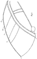
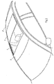
- an roof system (which is also known as a top slider roof) could comprise additional elements, such as for example a tiltable wind deflector positioned ahead of the roof opening 1, or further movable or stationary panels, for example in a position behind the panel 3 when it is in its closed position.
- the roof part behind the roof opening 3 is formed by a roof panel 2' which may be a stationary roof panel or a movable panel.
- Figs. 3 - 16 represent embodiments of an operating mechanism on one longitudinal side of the roof construction, i.e. one longitudinal side of the panel 3, and it should be understood that a corresponding operating mechanism normally will be provided at the opposite longitudinal side, generally in mirror image.
- Figs. 3 - 10 show the parts of a first embodiment of one of the operating mechanisms.
- the mechanism is connected to the panel 3 through a closure support, in this case a panel bracket 4 which is fixed to the lower side of the panel 3 near the longitudinal edge thereof in any known manner, for example through encapsulation or through attachment to another encapsulated part.
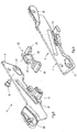
- the operating mechanism includes a first or rear device 5 and a second or front device 6 (see Fig. 4 ).
- the second or front device 6 includes a lever 7.
- This lever comprises a lower pivot axis, here a pivot pin 8, an upper pivotal connection 9, pivotally connecting the lever 7 to the panel bracket 4 of the panel 3, and an intermediate guide connection 10, here in the form of a cam.
- an intermediate guide connection 10 here in the form of a cam.
- a guide member 11 in the form of a guide cam.
- This guide member 11 is adapted to be in sliding engagement with a stationary guide curve 12. As shown in Fig. 7 (and Figs.
- the stationary guide curve includes a rear portion 12'' extending substantially parallel to the guide rail 13 (and panel 3 when in closed position), and a front portion 12' extending substantially at an angle to the rear portion 12''.
- the guide member 11 has a substantially oval shape, the height of the guide curve 12 varies along its length depending on the orientation of the guide curve 12, but also on the projected orientation of the lever 7 and the variation of this orientation of the lever 7 along the length of the guide curve 12.
- the front portion 12' of the stationary guide curve 12 is made in a plastic part which is attached to a stationary guide rail 13 which is attached to the vehicle roof, either directly or through a frame.
- the guide rail extends at least along the roof opening 1 in longitudinal direction of the vehicle.
- the main part of the rear portion 12" of the stationary guide curve 12 will generally be formed by flanges 13' of the stationary guide rail 13 (see Fig. 10 ).
- the stationary guide curve locks the horizontal movement of the panel 3 when it is in its forward position (through portion 12'), and locks the vertical movements of the panel when the panel is in the rearward position (through portion 12'').
- the intermediate guide connection 10 co-operates with a guiding slide 14 ( Figs. 4 and 5 ) which will generally be connected directly to a driving mechanism, for example an electric motor driving a push and pull cable 14' ( Fig. 10 ) and therefore also acts as a driving slide.
- the guiding slide 14 is slidebly guided in the stationary guide rail 13 and determines the movements of the panel 3.
- the guiding slide 14 includes a front guide curve, here a guide slot, 15 in which the cam of the intermediate guide connection 10 slidably engages.
- the front guide curve 15 includes a substantially vertical front locking portion 15', a lower front portion 15" and a rear portion 15''' which is open on its lower side so that the cam of the intermediate guide connection projects in the guide rail there. The extent of the front guide curve 15 determines the vertical movements of the front edge of the panel 3.
- the first or rear device 5 of the operating mechanism includes a lever 16 ( Fig. 3 and 4 ).
- This lever 16 comprises a lower pivot axis or pivot pin 17, an upper pivotal connection 18 and an intermediate guide connection 19.
- Both levers 7 and 16 extend in opposite directions, that is the front lever 7 extends from its connection to the panel 3 backwardly and downwardly, whereas the rear lever 16 extends forwardly and downwardly from the panel 3.
- both levers can be controlled by the same guiding slide 14 having a relatively short length, whereas the levers 7 and 16 connect to the panel 3 at a position near the front or rear edge respectively. This close connection to the front and rear edge of the panel 3 makes the support of the panel 3 very stable.
- the slidable connection between the rear lever 16 of the first device 5 and the guiding slide 14 is accomplished by the engagement of the pin 17 and of a cam of the intermediate guide connection 19 with a rear guide track.
- the rear guide track in the embodiment as shown in Fig. 5 includes two separate guide tracks or slots 20, 21, one for the pin 17 and one for the intermediate guide connection 19 as the paths of movement thereof do not overlap.
- the guide track 20 includes a lower front portion 20', a rearwardly and upwardly inclining portion 20", a high portion 20''', a vertical portion 20"" and a lower rear portion 20'''''.
- the pin 17 slides only in the portions 20', 20" and 20''' during use. The other portions are only used for mounting the rear lever 16 to guiding slide 14.
- the guide track 21 includes a substantially horizontal front portion 21', a second slightly lower substantially horizontal portion 21'', a rearwardly and downwardly inclining portion 21''', and a substantially horizontal rear portion 21"".
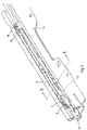
- the pivot pin 8 according to the operating mechanism of the present roof system is not engaged with the guiding slide 14, but is supported by a separate auxiliary sliding member 22 (see Figs. 4 , 8 and 10 ).
- This sliding member 22 is guided directly in the guide rail 13, that is in a guide channel 23 thereof. It includes a front and rear slide shoe 24 and 25 and central slide shoes 26 and 27.
- the front and rear slide shoes 24, 25 support the sliding member 22 at least in vertical downward direction for example on the bottom of the guide channel 23.
- the central slide shoe 26 is positioned below an upper horizontal flange 28 of the guide channel 23, whereas both central slide shoes 26, 27 engage a vertical guide flange 29 of the guide channel 23, each on an opposite surface thereof.
- the free end of this vertical guide flange 29 is also in engagement with the guide shoes 26, 27.
- the sliding member 22 is supported by the guide channel 23 in upward and sideward direction close to the pivot pin 8, so that the pivot pin receives a very good support under high loads.
- the sliding member 22 may be made completely of plastic or may for example be made of a steel body part 30 with the plastic slide shoes 24 - 27 moulded around this steel part 30, as is shown in Figs. 8 and 10 .
- Pivot pin 8 is fixed to the steel part 30 of the sliding member 22 and the front lever 7 is provided with a plastic moulding 31 acting as a bearing for the lever 7 on the pivot pin 8. This may or may not also provide for a lateral support of the front lever 7, i.e. in axial direction of the pivot pin 8.
- Figs. 4 , 8 and 9 show that the front lever 7 comprises near its upper pivotal connection 9 a slide shoe 32 that is guided by the upper side of the guiding slide, in particular by an auxiliary guide track 33 ( Figs. 4 and 5 ) in order to guide and support the lever 7 at least when the cam of the intermediate guide connection 19 is in the open rear slot portion 15''' where thus the cam is not supported in downward direction.
- a front portion or ramp 33' of the guide track 33 slightly slopes upwardly to the front in order to lift the cam of the intermediate connection 19 from the open rear portion 15''' into the lower front portion 15".
- the panel bracket 4 comprises a lateral projection, here a horizontal lip 34, whereas the guiding slide 14 includes a shoulder 35 below which the lip 34 may engage when the panel is in its closed position in order to provide additional security against unwanted upward movements of the panel 3.
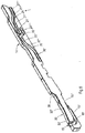
- Figs. 11 - 16 show a second embodiment of the operating mechanism. This operating mechanism is very similar to the first embodiment. Like parts are indicated with like reference numerals. Different in this second embodiment is that the slot of the front guide curve 15 is fully closed, and the front lever 7 does not have a slide shoe 32, and the guiding slide 14 no auxiliary guide track 33.
- FIG. 11 A further difference is to be seen in the sliding member 22 shown in Figs. 11 - 13 .
- This sliding member 22 is made completely of plastic or can have a metal core as in the first embodiment.
- the sliding member 22 is free from the bottom of the guide channel 23, so that any dirt on this bottom will have no influence on the sliding properties of the sliding member 22.
- the vertical flange 29 of the guide channel 23 has a horizontal end part 37 around which slide shoes 38 and 39 of the sliding member engage. These slide shoes 38 and 39 also engage the surface of the vertical flange 29, whereas an intermediate slide shoe 40 engages the opposite surface of the vertical flange 29.
- the plastic pivot pin 8 is formed in one piece with the sliding member 33 and engages into a bush which is formed directly in the (metal) front lever 7.
- Fig. 13 also shows a portion of a connecting part 41 connecting the cable 14' with the guiding slide 14 (at another position).
- Fig. 14 the operating mechanism is shown with the panel 3 in its closed position.
- the panel 3 will be pulled forcedly by the operating mechanism with its seals in engagement with the roof part 2, so that no leakage of noise from the environment to the interior of the vehicle will occur.
- the seals may either be fixed to the panel 3 or to the stationary roof part 2, or even to both.
- both levers 7 and 16 of the rear and front devices 5,6 are in their lowest position. This is accomplished by their engagement with the guiding slide 14 which is in its front position in the guide rail 13. In this front position of the guiding slide 14, the intermediate guide connection 10 of the front lever 7 is positioned near the rear end of the rear portion 15''' of the track 15.
- the guide member 11 of the lever 7 is positioned at the lower end of the front portion 12'' of the stationary guide curve 12.
- This front portion 12'' of the stationary guide curve 12 provides a very stable lock against sliding movements of the panel 3 along the stationary guide rail 13.
- the horizontal lip 34 is hooked below the shoulder 35 on the guiding slide 14.
- the upper wall of the front guide track 15 keeps the cam of the intermediate guide connection 10 down. Due to the arrangement of this intermediate guide connection 10 near the pivotal connection 9, due to the position of the pivotal connection 9 near the front edge of the panel 3, and due to the additional connection between the panel bracket 4 and the guiding slide 14 there is provided a very stable closed position of the panel at least near the front edge.
- the intermediate connection 10 is moved into the slightly inclined portion 15" of the track 15.
- the lower pivot pin 8 remains at a constant height, but is free to move longitudinally if necessary to allow movements of the lever 7.
- Fig. 16 shows a further position of the operating mechanism, in which the front edge of the panel 3 has been lifted upwardly and the panel has been slid rearwardly over the adjacent roof part 2'.
- the sliding movement of the panel 3 has been made possible by the arrival of the guide member 11 in the rearwardly extending portion of the stationary guide curve 12. This has been accomplished by the upward tilting movement of the lever 7 due to the entry of the intermediate guide connection 10 into the vertical front locking portion 15' of the front guide track 15 in the guiding slide 14.
- the levers 7 and 16 and therefore the panel 3 are now locked in sliding direction with respect to the guiding slide 14.
- the intermediate guide connection 10 is kept in its position in the front locking portion 15' due to the engagement of the guide member 11 with the rear portion 12" of the stationary guide curve 12 preventing a vertical movement of the lever 7.
- the panel 3 and the operating mechanism move as a unit.
- the roof panel 2' rearwardly of the roof opening 1 is bordered at its longitudinal sides by a slot 36, so that the guiding slide 14 may be slid far rearwardly below the stationary roof part 2, whereas the panel 3 may move over this roof part 2, because the rear lever 16 or even also the front lever 7 may project through this slot 36 above the guide rail 13.
- the slot is closed by a sealing arrangement, but the sealing arrangement is deformable so that the lever(s) may move through the slot 36 by pushing the seals of the sealing arrangement locally to the side.
- the operating mechanism connect the parts below the stationary roof part 2 to parts above the stationary roof part. This enables the operating mechanism to be moved far backwardly so as to create a large roof opening passage.
Landscapes
- Engineering & Computer Science (AREA)
- Mechanical Engineering (AREA)
- Fittings On The Vehicle Exterior For Carrying Loads, And Devices For Holding Or Mounting Articles (AREA)
- Lock And Its Accessories (AREA)
- Body Structure For Vehicles (AREA)
- Power-Operated Mechanisms For Wings (AREA)
Claims (14)
- Système de toit pour un véhicule ayant une ouverture de toit (1) dans une partie de toit (2, 2') de celui-ci, comprenant :au moins une fermeture (3) qui est mobile entre une position fermée dans laquelle elle ferme l'ouverture de toit et une position ouverte dans laquelle elle ouvre l'ouverture de toit et est positionnée au moins partiellement au-dessus d'une partie de toit contiguë (2') ;un rail de guidage immobile (13) au niveau de chaque côté longitudinal (1') de ladite ouverture de toit (1), adapté pour guider en coulissement un mécanisme d'actionnement qui actionne la fermeture (3) dans une direction longitudinale du véhicule, ledit mécanisme d'actionnement comprenant :un premier dispositif (5) incluant un levier (16) pour déplacer le bord arrière de la fermeture vers une position relevée par rapport à la position fermée et au-dessus de la partie de toit contiguë ;un second dispositif (6) incluant un levier (7) pour déplacer le bord avant de la fermeture dans une direction verticale ; etune coulisse de guidage qui est logée en coulissement dans chaque rail de guidage et est entraînable par un organe d'entraînement afin de déplacer la fermeture à la fois en direction verticale et horizontale par l'intermédiaire des premier et second dispositifs ;dans lequel l'un (7) desdits leviers (7; 16) a, au niveau d'une première extrémité, un premier raccord pivotant (9) avec la fermeture, et, éloignés de la première extrémité, des deuxième et troisième raccords espacés (8, 10) dont l'un (10) raccordant le levier respectif au moins à la coulisse de guidage (14) ;dans lequel ledit levier (7) est raccordé en pivotement à un organe coulissant (22) au niveau de l'autre desdits deuxième et troisième raccords (8, 10), ledit organe coulissant (22) étant séparé de la coulisse de guidage (14) et étant capable de coulisser dans la direction longitudinale du rail de guidage immobile (13) ;caractérisé en ce que l'organe coulissant (22) est supporté par le rail de guidage dans des directions perpendiculaires à la direction de coulissement longitudinale, ledit organe coulissant (22) étant guidé dans un canal de guidage (23) du rail de guidage (13), qui est pourvu d'une bride de guidage (28, 29) ayant une portion de bride verticale (29) qui est enclenchée par l'organe coulissant (22) près du deuxième ou troisième raccord (8, 10) respectif.
- Système de toit selon la revendication 1, dans lequel le deuxième raccord (8) est positionné près de la seconde extrémité dudit levier (7) et le troisième raccord (9) est positionné entre lesdits premier et deuxième raccords (10, 8).
- Système de toit selon la revendication 1, dans lequel l'au moins un desdits leviers (7) est raccordé à l'organe coulissant (22) au niveau du deuxième raccord (8).
- Système de toit selon l'une quelconque des revendications précédentes, dans lequel le levier avant (7) est raccordé audit organe coulissant (22).
- Système de toit selon l'une quelconque des revendications précédentes, dans lequel la bride de guidage (28, 29) a une portion horizontale (37) enclenchée par l'organe coulissant (22) espacée des côtés et du dessous de l'organe coulissant.
- Système de toit selon la revendication 1 ou 5, dans lequel la portion de bride verticale (29) est une portion de bride suspendue vers le bas qui est enclenchée par l'organe coulissant des deux côtés et espacée des côtés de l'organe coulissant (22).
- Système de toit selon l'une quelconque des revendications précédentes, dans lequel l'organe coulissant (22), dans une vue dans une direction longitudinale du rail de guidage (13), est supporté dans une direction vers le bas et vers le haut à des emplacements espacés.
- Système de toit selon l'une des revendications précédentes, dans lequel l'au moins un desdits leviers (7) est raccordé à la coulisse de guidage (14) au niveau du troisième raccord (10), qui comporte une came (10) sur le levier et une gorge (15) dans la coulisse de guidage.
- Système de toit selon la revendication 8, dans lequel la gorge (15) dans la coulisse de guidage (14) est une fente qui a une portion de fente ouverte vers le bas (15"') qui est ouverte au niveau de son dessous sur une étendue longitudinale qui est plus grande que la dimension longitudinale de la came (10) sur le levier (7) respectif, dans lequel la coulisse de guidage (14) sur son côté supérieur comprend une gorge de guidage auxiliaire (33) enclenchée par le levier (7) respectif au moins lorsque la came (10) est dans la portion de fente ouverte.
- Système de toit selon la revendication 9, dans lequel la gorge de guidage auxiliaire (33) comporte une portion de rampe (33') pour lever le levier (7) respectif lorsque la came est transférée de la portion de fente ouverte vers le bas (15"') à la portion de fente fermée vers le bas (15").
- Système de toit selon la revendication 9 ou 10, dans lequel le levier (7) respectif enclenche la gorge de guidage auxiliaire (33) sur la coulisse de guidage (14) à une position près de sa première extrémité.
- Système de toit selon l'une quelconque des revendications précédentes, dans lequel le raccord pivotant (8) entre l'au moins un desdits leviers (7; 16) et l'organe coulissant (22) comporte une broche et un palier, tel qu'un coussinet dans lequel la broche est renfermée en rotation.
- Système de toit selon l'une quelconque des revendications précédentes, comprenant en outre un mécanisme de guidage (11, 12) pour guider la fermeture vers la position ouverte lorsque son bord arrière est dans la position relevée, dans lequel le mécanisme de guidage (11, 12) comporte une courbe de guidage immobile (12) ayant une portion arrière (12') s'étendant sensiblement parallèle à la fermeture (3) dans la position fermée, et une portion avant (12") s'étendant en formant un angle avec la portion arrière dans un plan vertical, la courbe de guidage immobile étant enclenchée en coulissement par un organe de guidage (11) raccordé à la fermeture (3).
- Système de toit selon l'une quelconque des revendications précédentes, dans lequel la fermeture (3) est pourvue d'un support de fermeture (4) comprenant une saillie latérale (34), et dans lequel la coulisse de guidage (14) est pourvue d'un épaulement latéral (35), la saillie s'enclenchant sous l'épaulement lorsque la fermeture est dans la position fermée.
Priority Applications (1)
| Application Number | Priority Date | Filing Date | Title |
|---|---|---|---|
| EP14155790.0A EP2740622B1 (fr) | 2011-08-02 | 2011-08-02 | Système de toit pour véhicule |
Applications Claiming Priority (2)
| Application Number | Priority Date | Filing Date | Title |
|---|---|---|---|
| EP14155790.0A EP2740622B1 (fr) | 2011-08-02 | 2011-08-02 | Système de toit pour véhicule |
| EP11176299.3A EP2554415B2 (fr) | 2011-08-02 | 2011-08-02 | Système de toit pour véhicule |
Related Parent Applications (2)
| Application Number | Title | Priority Date | Filing Date |
|---|---|---|---|
| EP11176299.3A Division EP2554415B2 (fr) | 2011-08-02 | 2011-08-02 | Système de toit pour véhicule |
| EP11176299.3A Division-Into EP2554415B2 (fr) | 2011-08-02 | 2011-08-02 | Système de toit pour véhicule |
Publications (3)
| Publication Number | Publication Date |
|---|---|
| EP2740622A2 EP2740622A2 (fr) | 2014-06-11 |
| EP2740622A3 EP2740622A3 (fr) | 2014-08-13 |
| EP2740622B1 true EP2740622B1 (fr) | 2018-05-30 |
Family
ID=45497524
Family Applications (2)
| Application Number | Title | Priority Date | Filing Date |
|---|---|---|---|
| EP14155790.0A Active EP2740622B1 (fr) | 2011-08-02 | 2011-08-02 | Système de toit pour véhicule |
| EP11176299.3A Active EP2554415B2 (fr) | 2011-08-02 | 2011-08-02 | Système de toit pour véhicule |
Family Applications After (1)
| Application Number | Title | Priority Date | Filing Date |
|---|---|---|---|
| EP11176299.3A Active EP2554415B2 (fr) | 2011-08-02 | 2011-08-02 | Système de toit pour véhicule |
Country Status (6)
| Country | Link |
|---|---|
| US (2) | US8857903B2 (fr) |
| EP (2) | EP2740622B1 (fr) |
| JP (1) | JP6218364B2 (fr) |
| KR (1) | KR101960243B1 (fr) |
| CN (1) | CN102910054B (fr) |
| MX (1) | MX2012008923A (fr) |
Families Citing this family (41)
| Publication number | Priority date | Publication date | Assignee | Title |
|---|---|---|---|---|
| EP2380763B1 (fr) * | 2010-04-20 | 2013-06-12 | Inalfa Roof Systems Group B.V. | Construction décapotable pour véhicule |
| EP2774794B1 (fr) * | 2013-03-04 | 2016-05-18 | Webasto SE | Dispositif de toit coulissant de véhicule |
| DE102013216292B4 (de) * | 2013-08-16 | 2017-10-26 | Bos Gmbh & Co. Kg | Antriebssystem für einen beweglichen Dachteil eines Dachmoduls eines Kraftfahrzeugs |
| DE102013109097B3 (de) | 2013-08-22 | 2014-12-31 | Webasto SE | Anordnung für ein Fahrzeugdach mit einem Deckel |
| KR101531258B1 (ko) * | 2013-12-31 | 2015-06-25 | (주)베바스토동희 홀딩스 | 선루프의 와인딩 가이드와 슬레드 연동장치 |
| KR101531250B1 (ko) * | 2013-12-31 | 2015-06-25 | (주)베바스토동희 홀딩스 | 다중 궤적을 이용한 선루프 글래스 구동장치 |
| KR101531253B1 (ko) * | 2013-12-31 | 2015-06-25 | (주)베바스토동희 홀딩스 | 슬레드 연동구조를 갖는 자동차용 선루프 글래스 메카니즘 구동장치 |
| KR101531247B1 (ko) * | 2013-12-31 | 2015-06-25 | (주)베바스토동희 홀딩스 | 2중 궤적을 이용한 글래스 구속전환장치 |
| DE102014107662B3 (de) * | 2014-05-30 | 2015-10-22 | Webasto SE | Anordnung mit einem Deckel für ein Fahrzeugdach |
| DE202014102693U1 (de) | 2014-06-11 | 2015-09-15 | Inalfa Roof Systems Group B.V. | Dachsystem für ein Fahrzeug |
| DE202014103089U1 (de) | 2014-07-04 | 2015-10-06 | Inalfa Roof Systems Group B.V. | Dachsystem für ein Fahrzeug |
| KR101632579B1 (ko) * | 2014-11-05 | 2016-06-23 | (주)베바스토동희 홀딩스 | 자동차 선루프의 글라스 이동장치 |
| CN104385888A (zh) * | 2014-11-12 | 2015-03-04 | 上海万超汽车天窗有限公司 | 倾斜滑动天窗机构 |
| DE102014117151B4 (de) * | 2014-11-24 | 2023-11-09 | Webasto SE | Anordnung für ein Fahrzeugdach |
| DE102014018285A1 (de) * | 2014-12-12 | 2016-06-16 | Webasto SE | Fahrzeug mit einem Gleiter zum Führen eines verlagerbaren Elements |
| EP3034343B1 (fr) * | 2014-12-17 | 2020-05-13 | Inalfa Roof Systems Group B.V. | Système de toit pour véhicule |
| CN104943516B (zh) * | 2015-07-28 | 2017-06-23 | 芜湖莫森泰克汽车科技股份有限公司 | 一种具有全景天窗半固定式机构的汽车及其开启方法 |
| EP3130495B1 (fr) | 2015-08-11 | 2018-03-14 | Inalfa Roof Systems Group B.V. | Construction décapotable pour véhicule |
| DE102015120408B3 (de) * | 2015-11-25 | 2017-03-09 | Webasto SE | Deckel eines Fahrzeugdaches mit Einlegeteil in einem Kunststoffformabschnitt |
| DE102015121533A1 (de) * | 2015-12-10 | 2017-06-14 | Webasto SE | Öffnungsfähiges Fahrzeugdach, umfassend Verstellkinematik mit Koppelstange |
| DE102017201402A1 (de) | 2017-01-30 | 2018-08-02 | Bos Gmbh & Co. Kg | Schiebedachsystem für ein Kraftfahrzeug |
| WO2019024996A1 (fr) | 2017-08-03 | 2019-02-07 | Inalfa Roof Systems Group B.V. | Structure de toit ouvrant pour véhicule |
| DE102018101557A1 (de) * | 2017-08-03 | 2019-02-07 | Webasto SE | Rolloanordnung mit Führungsbändern für Rollobahn |
| EP3476633B1 (fr) * | 2017-10-31 | 2023-05-24 | Inalfa Roof Systems Group B.V. | Système de toit pour véhicule |
| DE202017107486U1 (de) * | 2017-12-08 | 2019-03-12 | Inalfa Roof Systems Group B.V. | Offendachkonstruktion für ein Fahrzeug, und Fahrzeug mit einer solchen Offendachkonstruktion |
| WO2019122955A1 (fr) | 2017-12-19 | 2019-06-27 | Jubilee Diamond Instrument (S) Pte.Ltd. | Appareil de test de pierres précieuses |
| US10837915B2 (en) | 2017-12-19 | 2020-11-17 | Jubilee Diamond Instrument (s) PTE. LTD | Gemstone testing apparatus |
| EP3552853B1 (fr) | 2018-04-12 | 2021-01-27 | Inalfa Roof Systems Group B.V. | Système de toit ouvrant pour un véhicule avec glissière d'entraînement rotative |
| US10525802B2 (en) | 2018-06-05 | 2020-01-07 | Honda Motor Co., Ltd. | Roof system for use in a vehicle |
| DE102018124382B4 (de) * | 2018-10-02 | 2023-06-29 | Webasto SE | Fahrzeugdach mit Dachöffnungssystem und Antriebseinrichtung für Kinematikeinheiten |
| US10611216B1 (en) | 2018-10-11 | 2020-04-07 | AISIN Technical Center of America, Inc. | Anti-rotation sunroof drive link |
| US10618388B1 (en) | 2018-10-11 | 2020-04-14 | AISIN Technical Center of America, Inc. | Sunroof high speed catch device |
| US10647185B2 (en) | 2018-10-11 | 2020-05-12 | AISIN Technical Center of America, Inc. | Drive link apparatus for use with vehicle sunroofs |
| DE102018130016A1 (de) * | 2018-11-27 | 2020-05-28 | Roof Systems Germany Gmbh | Schiebedachsystem für ein Kraftfahrzeug |
| DE102018130013A1 (de) * | 2018-11-27 | 2020-05-28 | Roof Systems Germany Gmbh | Schiebedachsystem für ein Kraftfahrzeug |
| CN109484147B (zh) * | 2019-01-10 | 2019-09-17 | 江苏铁锚明信交通科技有限公司 | 一种全景天窗玻璃运动机构总成 |
| DE102019113142A1 (de) * | 2019-05-17 | 2020-11-19 | Webasto SE | Anordnung und Verfahren zum Bewegen eines Deckels |
| EP3771578B1 (fr) | 2019-07-29 | 2022-06-08 | Inalfa Roof Systems Group B.V. | Structure décapotable pour véhicule |
| EP3795394B1 (fr) * | 2019-09-19 | 2023-11-01 | Inalfa Roof Systems Group B.V. | Rail de guidage pour un ensemble de guidage d'un système de toit ouvrant |
| EP3944976B1 (fr) | 2020-07-27 | 2023-09-27 | Inalfa Roof Systems Group B.V. | Panneau et construction de toit ouvrant comportant celui-ci |
| EP4289647A1 (fr) | 2022-06-08 | 2023-12-13 | Inalfa Roof Systems Group B.V. | Système de toit pour véhicule |
Family Cites Families (12)
| Publication number | Priority date | Publication date | Assignee | Title |
|---|---|---|---|---|
| DE19609188C1 (de) | 1996-03-09 | 1997-04-24 | Webasto Karosseriesysteme | Betätigungsmechanik für ein öffnungsfähiges Fahrzeugdach |
| DE19756020C1 (de) * | 1997-12-17 | 1999-01-07 | Webasto Karosseriesysteme | Schiebedach |
| DE10055790B4 (de) * | 2000-11-10 | 2005-03-17 | Webasto Ag | Öffnungsfähiges Fahrzeugdach |
| DE102004018461A1 (de) | 2004-04-16 | 2005-11-03 | Arvinmeritor Gmbh | Schiebedachsystem |
| DE102005030056B3 (de) * | 2005-06-27 | 2006-08-03 | Webasto Ag | Fahrzeugdach mit einem oberhalb des Daches verschiebbaren Dachteil |
| DE602005024793D1 (de) * | 2005-07-08 | 2010-12-30 | Inalfa Roof Sys Group Bv | Öffnungsfähige Dachkonstruktion für ein Fahrzeug |
| EP1790515A1 (fr) * | 2005-11-23 | 2007-05-30 | ArvinMeritor GmbH | Mécanisme pour soulever un toit ouvrant et un toit de véhicule avec tel mécanisme |
| DE102005058007A1 (de) | 2005-12-05 | 2007-06-06 | Webasto Ag | Führungsmechanik für ein Schiebedach, Schiebedach und Kraftfahrzeug mit Schiebedach |
| DE102006002064B4 (de) † | 2006-01-16 | 2008-03-20 | Webasto Ag | Fahrzeugdach mit einem oberhalb eines festen Dachabschnitts verschiebbaren Deckel |
| DE102007003177B4 (de) | 2007-01-22 | 2012-10-18 | Webasto Ag | Gleitbacke |
| DE102007004258A1 (de) * | 2007-01-23 | 2008-07-24 | Webasto Ag | Fahrzeugdach mit einem öffnungsfähigen Dachteil |
| DE602008005546D1 (de) | 2008-01-10 | 2011-04-28 | Inalfa Roof Sys Group Bv | Offene Dachkonstruktion für ein Fahrzeug |
-
2011
- 2011-08-02 EP EP14155790.0A patent/EP2740622B1/fr active Active
- 2011-08-02 EP EP11176299.3A patent/EP2554415B2/fr active Active
-
2012
- 2012-07-26 US US13/559,154 patent/US8857903B2/en active Active
- 2012-07-31 JP JP2012169308A patent/JP6218364B2/ja active Active
- 2012-08-01 MX MX2012008923A patent/MX2012008923A/es active IP Right Grant
- 2012-08-01 KR KR1020120084450A patent/KR101960243B1/ko active IP Right Grant
- 2012-08-01 CN CN201210271469.XA patent/CN102910054B/zh active Active
-
2014
- 2014-10-07 US US14/508,717 patent/US9227493B2/en active Active
Also Published As
| Publication number | Publication date |
|---|---|
| EP2554415B2 (fr) | 2020-12-02 |
| US20130187412A1 (en) | 2013-07-25 |
| CN102910054B (zh) | 2016-12-21 |
| JP2013032150A (ja) | 2013-02-14 |
| CN102910054A (zh) | 2013-02-06 |
| MX2012008923A (es) | 2013-02-19 |
| US20150021957A1 (en) | 2015-01-22 |
| US8857903B2 (en) | 2014-10-14 |
| EP2554415A1 (fr) | 2013-02-06 |
| EP2740622A2 (fr) | 2014-06-11 |
| KR20130018581A (ko) | 2013-02-25 |
| JP6218364B2 (ja) | 2017-10-25 |
| EP2740622A3 (fr) | 2014-08-13 |
| US9227493B2 (en) | 2016-01-05 |
| KR101960243B1 (ko) | 2019-03-21 |
| EP2554415B1 (fr) | 2014-02-26 |
Similar Documents
| Publication | Publication Date | Title |
|---|---|---|
| EP2740622B1 (fr) | Système de toit pour véhicule | |
| EP2078630B1 (fr) | Construction de toit ouvrant pour véhicule | |
| US7178862B2 (en) | Sliding roof system | |
| EP3034343B1 (fr) | Système de toit pour véhicule | |
| US8616623B2 (en) | Vehicle sunroof device | |
| US5718472A (en) | Automotive slide roof system | |
| US11331988B2 (en) | Roof system for a vehicle | |
| US6942285B2 (en) | Vehicle and roof assembly | |
| US7367614B2 (en) | Multi-panel sunshade device | |
| CN111137118A (zh) | 用于车辆的车顶系统 | |
| US8297692B2 (en) | Tiltable sun roof for vehicles | |
| EP4289647A1 (fr) | Système de toit pour véhicule | |
| US11607937B2 (en) | Roof system for a vehicle | |
| US20230022266A1 (en) | Roof system | |
| JPH0215693Y2 (fr) | ||
| CN113306373A (zh) | 用于车辆的车顶打开构造 |
Legal Events
| Date | Code | Title | Description |
|---|---|---|---|
| PUAI | Public reference made under article 153(3) epc to a published international application that has entered the european phase |
Free format text: ORIGINAL CODE: 0009012 |
|
| 17P | Request for examination filed |
Effective date: 20140219 |
|
| AC | Divisional application: reference to earlier application |
Ref document number: 2554415 Country of ref document: EP Kind code of ref document: P |
|
| AK | Designated contracting states |
Kind code of ref document: A2 Designated state(s): AL AT BE BG CH CY CZ DE DK EE ES FI FR GB GR HR HU IE IS IT LI LT LU LV MC MK MT NL NO PL PT RO RS SE SI SK SM TR |
|
| PUAL | Search report despatched |
Free format text: ORIGINAL CODE: 0009013 |
|
| AK | Designated contracting states |
Kind code of ref document: A3 Designated state(s): AL AT BE BG CH CY CZ DE DK EE ES FI FR GB GR HR HU IE IS IT LI LT LU LV MC MK MT NL NO PL PT RO RS SE SI SK SM TR |
|
| RIC1 | Information provided on ipc code assigned before grant |
Ipc: B60J 7/02 20060101AFI20140708BHEP Ipc: B60J 7/043 20060101ALI20140708BHEP Ipc: B60J 7/047 20060101ALI20140708BHEP |
|
| R17P | Request for examination filed (corrected) |
Effective date: 20150211 |
|
| RBV | Designated contracting states (corrected) |
Designated state(s): AL AT BE BG CH CY CZ DE DK EE ES FI FR GB GR HR HU IE IS IT LI LT LU LV MC MK MT NL NO PL PT RO RS SE SI SK SM TR |
|
| RIC1 | Information provided on ipc code assigned before grant |
Ipc: B60J 7/02 20060101AFI20171218BHEP Ipc: B60J 7/043 20060101ALI20171218BHEP Ipc: B60J 7/047 20060101ALI20171218BHEP |
|
| GRAP | Despatch of communication of intention to grant a patent |
Free format text: ORIGINAL CODE: EPIDOSNIGR1 |
|
| INTG | Intention to grant announced |
Effective date: 20180202 |
|
| GRAJ | Information related to disapproval of communication of intention to grant by the applicant or resumption of examination proceedings by the epo deleted |
Free format text: ORIGINAL CODE: EPIDOSDIGR1 |
|
| GRAR | Information related to intention to grant a patent recorded |
Free format text: ORIGINAL CODE: EPIDOSNIGR71 |
|
| GRAS | Grant fee paid |
Free format text: ORIGINAL CODE: EPIDOSNIGR3 |
|
| GRAA | (expected) grant |
Free format text: ORIGINAL CODE: 0009210 |
|
| INTG | Intention to grant announced |
Effective date: 20180419 |
|
| AC | Divisional application: reference to earlier application |
Ref document number: 2554415 Country of ref document: EP Kind code of ref document: P |
|
| AK | Designated contracting states |
Kind code of ref document: B1 Designated state(s): AL AT BE BG CH CY CZ DE DK EE ES FI FR GB GR HR HU IE IS IT LI LT LU LV MC MK MT NL NO PL PT RO RS SE SI SK SM TR |
|
| REG | Reference to a national code |
Ref country code: GB Ref legal event code: FG4D |
|
| REG | Reference to a national code |
Ref country code: CH Ref legal event code: EP |
|
| REG | Reference to a national code |
Ref country code: AT Ref legal event code: REF Ref document number: 1003245 Country of ref document: AT Kind code of ref document: T Effective date: 20180615 |
|
| REG | Reference to a national code |
Ref country code: IE Ref legal event code: FG4D |
|
| REG | Reference to a national code |
Ref country code: DE Ref legal event code: R096 Ref document number: 602011048966 Country of ref document: DE |
|
| REG | Reference to a national code |
Ref country code: FR Ref legal event code: PLFP Year of fee payment: 8 |
|
| REG | Reference to a national code |
Ref country code: NL Ref legal event code: MP Effective date: 20180530 |
|
| REG | Reference to a national code |
Ref country code: LT Ref legal event code: MG4D |
|
| PG25 | Lapsed in a contracting state [announced via postgrant information from national office to epo] |
Ref country code: FI Free format text: LAPSE BECAUSE OF FAILURE TO SUBMIT A TRANSLATION OF THE DESCRIPTION OR TO PAY THE FEE WITHIN THE PRESCRIBED TIME-LIMIT Effective date: 20180530 Ref country code: BG Free format text: LAPSE BECAUSE OF FAILURE TO SUBMIT A TRANSLATION OF THE DESCRIPTION OR TO PAY THE FEE WITHIN THE PRESCRIBED TIME-LIMIT Effective date: 20180830 Ref country code: CY Free format text: LAPSE BECAUSE OF FAILURE TO SUBMIT A TRANSLATION OF THE DESCRIPTION OR TO PAY THE FEE WITHIN THE PRESCRIBED TIME-LIMIT Effective date: 20180530 Ref country code: LT Free format text: LAPSE BECAUSE OF FAILURE TO SUBMIT A TRANSLATION OF THE DESCRIPTION OR TO PAY THE FEE WITHIN THE PRESCRIBED TIME-LIMIT Effective date: 20180530 Ref country code: SE Free format text: LAPSE BECAUSE OF FAILURE TO SUBMIT A TRANSLATION OF THE DESCRIPTION OR TO PAY THE FEE WITHIN THE PRESCRIBED TIME-LIMIT Effective date: 20180530 Ref country code: ES Free format text: LAPSE BECAUSE OF FAILURE TO SUBMIT A TRANSLATION OF THE DESCRIPTION OR TO PAY THE FEE WITHIN THE PRESCRIBED TIME-LIMIT Effective date: 20180530 Ref country code: NO Free format text: LAPSE BECAUSE OF FAILURE TO SUBMIT A TRANSLATION OF THE DESCRIPTION OR TO PAY THE FEE WITHIN THE PRESCRIBED TIME-LIMIT Effective date: 20180830 |
|
| PG25 | Lapsed in a contracting state [announced via postgrant information from national office to epo] |
Ref country code: RS Free format text: LAPSE BECAUSE OF FAILURE TO SUBMIT A TRANSLATION OF THE DESCRIPTION OR TO PAY THE FEE WITHIN THE PRESCRIBED TIME-LIMIT Effective date: 20180530 Ref country code: HR Free format text: LAPSE BECAUSE OF FAILURE TO SUBMIT A TRANSLATION OF THE DESCRIPTION OR TO PAY THE FEE WITHIN THE PRESCRIBED TIME-LIMIT Effective date: 20180530 Ref country code: GR Free format text: LAPSE BECAUSE OF FAILURE TO SUBMIT A TRANSLATION OF THE DESCRIPTION OR TO PAY THE FEE WITHIN THE PRESCRIBED TIME-LIMIT Effective date: 20180831 Ref country code: LV Free format text: LAPSE BECAUSE OF FAILURE TO SUBMIT A TRANSLATION OF THE DESCRIPTION OR TO PAY THE FEE WITHIN THE PRESCRIBED TIME-LIMIT Effective date: 20180530 |
|
| REG | Reference to a national code |
Ref country code: AT Ref legal event code: MK05 Ref document number: 1003245 Country of ref document: AT Kind code of ref document: T Effective date: 20180530 |
|
| PG25 | Lapsed in a contracting state [announced via postgrant information from national office to epo] |
Ref country code: NL Free format text: LAPSE BECAUSE OF FAILURE TO SUBMIT A TRANSLATION OF THE DESCRIPTION OR TO PAY THE FEE WITHIN THE PRESCRIBED TIME-LIMIT Effective date: 20180530 |
|
| PG25 | Lapsed in a contracting state [announced via postgrant information from national office to epo] |
Ref country code: SK Free format text: LAPSE BECAUSE OF FAILURE TO SUBMIT A TRANSLATION OF THE DESCRIPTION OR TO PAY THE FEE WITHIN THE PRESCRIBED TIME-LIMIT Effective date: 20180530 Ref country code: PL Free format text: LAPSE BECAUSE OF FAILURE TO SUBMIT A TRANSLATION OF THE DESCRIPTION OR TO PAY THE FEE WITHIN THE PRESCRIBED TIME-LIMIT Effective date: 20180530 Ref country code: CZ Free format text: LAPSE BECAUSE OF FAILURE TO SUBMIT A TRANSLATION OF THE DESCRIPTION OR TO PAY THE FEE WITHIN THE PRESCRIBED TIME-LIMIT Effective date: 20180530 Ref country code: AT Free format text: LAPSE BECAUSE OF FAILURE TO SUBMIT A TRANSLATION OF THE DESCRIPTION OR TO PAY THE FEE WITHIN THE PRESCRIBED TIME-LIMIT Effective date: 20180530 Ref country code: RO Free format text: LAPSE BECAUSE OF FAILURE TO SUBMIT A TRANSLATION OF THE DESCRIPTION OR TO PAY THE FEE WITHIN THE PRESCRIBED TIME-LIMIT Effective date: 20180530 Ref country code: DK Free format text: LAPSE BECAUSE OF FAILURE TO SUBMIT A TRANSLATION OF THE DESCRIPTION OR TO PAY THE FEE WITHIN THE PRESCRIBED TIME-LIMIT Effective date: 20180530 Ref country code: EE Free format text: LAPSE BECAUSE OF FAILURE TO SUBMIT A TRANSLATION OF THE DESCRIPTION OR TO PAY THE FEE WITHIN THE PRESCRIBED TIME-LIMIT Effective date: 20180530 |
|
| PG25 | Lapsed in a contracting state [announced via postgrant information from national office to epo] |
Ref country code: SM Free format text: LAPSE BECAUSE OF FAILURE TO SUBMIT A TRANSLATION OF THE DESCRIPTION OR TO PAY THE FEE WITHIN THE PRESCRIBED TIME-LIMIT Effective date: 20180530 Ref country code: IT Free format text: LAPSE BECAUSE OF FAILURE TO SUBMIT A TRANSLATION OF THE DESCRIPTION OR TO PAY THE FEE WITHIN THE PRESCRIBED TIME-LIMIT Effective date: 20180530 |
|
| REG | Reference to a national code |
Ref country code: DE Ref legal event code: R097 Ref document number: 602011048966 Country of ref document: DE |
|
| PG25 | Lapsed in a contracting state [announced via postgrant information from national office to epo] |
Ref country code: MC Free format text: LAPSE BECAUSE OF FAILURE TO SUBMIT A TRANSLATION OF THE DESCRIPTION OR TO PAY THE FEE WITHIN THE PRESCRIBED TIME-LIMIT Effective date: 20180530 |
|
| REG | Reference to a national code |
Ref country code: CH Ref legal event code: PL |
|
| PLBE | No opposition filed within time limit |
Free format text: ORIGINAL CODE: 0009261 |
|
| STAA | Information on the status of an ep patent application or granted ep patent |
Free format text: STATUS: NO OPPOSITION FILED WITHIN TIME LIMIT |
|
| GBPC | Gb: european patent ceased through non-payment of renewal fee |
Effective date: 20180830 |
|
| PG25 | Lapsed in a contracting state [announced via postgrant information from national office to epo] |
Ref country code: CH Free format text: LAPSE BECAUSE OF NON-PAYMENT OF DUE FEES Effective date: 20180831 Ref country code: LU Free format text: LAPSE BECAUSE OF NON-PAYMENT OF DUE FEES Effective date: 20180802 Ref country code: LI Free format text: LAPSE BECAUSE OF NON-PAYMENT OF DUE FEES Effective date: 20180831 |
|
| 26N | No opposition filed |
Effective date: 20190301 |
|
| REG | Reference to a national code |
Ref country code: BE Ref legal event code: MM Effective date: 20180831 |
|
| REG | Reference to a national code |
Ref country code: IE Ref legal event code: MM4A |
|
| PG25 | Lapsed in a contracting state [announced via postgrant information from national office to epo] |
Ref country code: SI Free format text: LAPSE BECAUSE OF FAILURE TO SUBMIT A TRANSLATION OF THE DESCRIPTION OR TO PAY THE FEE WITHIN THE PRESCRIBED TIME-LIMIT Effective date: 20180530 |
|
| PG25 | Lapsed in a contracting state [announced via postgrant information from national office to epo] |
Ref country code: IE Free format text: LAPSE BECAUSE OF NON-PAYMENT OF DUE FEES Effective date: 20180802 |
|
| PG25 | Lapsed in a contracting state [announced via postgrant information from national office to epo] |
Ref country code: BE Free format text: LAPSE BECAUSE OF NON-PAYMENT OF DUE FEES Effective date: 20180831 |
|
| PG25 | Lapsed in a contracting state [announced via postgrant information from national office to epo] |
Ref country code: GB Free format text: LAPSE BECAUSE OF NON-PAYMENT OF DUE FEES Effective date: 20180830 |
|
| PG25 | Lapsed in a contracting state [announced via postgrant information from national office to epo] |
Ref country code: AL Free format text: LAPSE BECAUSE OF FAILURE TO SUBMIT A TRANSLATION OF THE DESCRIPTION OR TO PAY THE FEE WITHIN THE PRESCRIBED TIME-LIMIT Effective date: 20180530 |
|
| PG25 | Lapsed in a contracting state [announced via postgrant information from national office to epo] |
Ref country code: MT Free format text: LAPSE BECAUSE OF NON-PAYMENT OF DUE FEES Effective date: 20180802 |
|
| PG25 | Lapsed in a contracting state [announced via postgrant information from national office to epo] |
Ref country code: TR Free format text: LAPSE BECAUSE OF FAILURE TO SUBMIT A TRANSLATION OF THE DESCRIPTION OR TO PAY THE FEE WITHIN THE PRESCRIBED TIME-LIMIT Effective date: 20180530 |
|
| PG25 | Lapsed in a contracting state [announced via postgrant information from national office to epo] |
Ref country code: HU Free format text: LAPSE BECAUSE OF FAILURE TO SUBMIT A TRANSLATION OF THE DESCRIPTION OR TO PAY THE FEE WITHIN THE PRESCRIBED TIME-LIMIT; INVALID AB INITIO Effective date: 20110802 Ref country code: PT Free format text: LAPSE BECAUSE OF FAILURE TO SUBMIT A TRANSLATION OF THE DESCRIPTION OR TO PAY THE FEE WITHIN THE PRESCRIBED TIME-LIMIT Effective date: 20180530 |
|
| PG25 | Lapsed in a contracting state [announced via postgrant information from national office to epo] |
Ref country code: MK Free format text: LAPSE BECAUSE OF NON-PAYMENT OF DUE FEES Effective date: 20180530 |
|
| PG25 | Lapsed in a contracting state [announced via postgrant information from national office to epo] |
Ref country code: IS Free format text: LAPSE BECAUSE OF FAILURE TO SUBMIT A TRANSLATION OF THE DESCRIPTION OR TO PAY THE FEE WITHIN THE PRESCRIBED TIME-LIMIT Effective date: 20180930 |
|
| PGFP | Annual fee paid to national office [announced via postgrant information from national office to epo] |
Ref country code: FR Payment date: 20230825 Year of fee payment: 13 Ref country code: DE Payment date: 20230829 Year of fee payment: 13 |