EP2732984A1 - Radialluftreifen - Google Patents
Radialluftreifen Download PDFInfo
- Publication number
- EP2732984A1 EP2732984A1 EP12811699.3A EP12811699A EP2732984A1 EP 2732984 A1 EP2732984 A1 EP 2732984A1 EP 12811699 A EP12811699 A EP 12811699A EP 2732984 A1 EP2732984 A1 EP 2732984A1
- Authority
- EP
- European Patent Office
- Prior art keywords
- tread
- tire
- lateral groove
- width direction
- groove
- Prior art date
- Legal status (The legal status is an assumption and is not a legal conclusion. Google has not performed a legal analysis and makes no representation as to the accuracy of the status listed.)
- Granted
Links
Images


Classifications
-
- B—PERFORMING OPERATIONS; TRANSPORTING
- B60—VEHICLES IN GENERAL
- B60C—VEHICLE TYRES; TYRE INFLATION; TYRE CHANGING; CONNECTING VALVES TO INFLATABLE ELASTIC BODIES IN GENERAL; DEVICES OR ARRANGEMENTS RELATED TO TYRES
- B60C11/00—Tyre tread bands; Tread patterns; Anti-skid inserts
- B60C11/03—Tread patterns
- B60C11/0302—Tread patterns directional pattern, i.e. with main rolling direction
-
- B—PERFORMING OPERATIONS; TRANSPORTING
- B60—VEHICLES IN GENERAL
- B60C—VEHICLE TYRES; TYRE INFLATION; TYRE CHANGING; CONNECTING VALVES TO INFLATABLE ELASTIC BODIES IN GENERAL; DEVICES OR ARRANGEMENTS RELATED TO TYRES
- B60C11/00—Tyre tread bands; Tread patterns; Anti-skid inserts
- B60C11/03—Tread patterns
- B60C11/0311—Patterns comprising tread lugs arranged parallel or oblique to the axis of rotation
- B60C11/0316—Patterns comprising tread lugs arranged parallel or oblique to the axis of rotation further characterised by the groove cross-section
-
- B—PERFORMING OPERATIONS; TRANSPORTING
- B60—VEHICLES IN GENERAL
- B60C—VEHICLE TYRES; TYRE INFLATION; TYRE CHANGING; CONNECTING VALVES TO INFLATABLE ELASTIC BODIES IN GENERAL; DEVICES OR ARRANGEMENTS RELATED TO TYRES
- B60C11/00—Tyre tread bands; Tread patterns; Anti-skid inserts
- B60C11/03—Tread patterns
- B60C11/0311—Patterns comprising tread lugs arranged parallel or oblique to the axis of rotation
-
- B—PERFORMING OPERATIONS; TRANSPORTING
- B60—VEHICLES IN GENERAL
- B60C—VEHICLE TYRES; TYRE INFLATION; TYRE CHANGING; CONNECTING VALVES TO INFLATABLE ELASTIC BODIES IN GENERAL; DEVICES OR ARRANGEMENTS RELATED TO TYRES
- B60C11/00—Tyre tread bands; Tread patterns; Anti-skid inserts
- B60C11/03—Tread patterns
- B60C11/13—Tread patterns characterised by the groove cross-section, e.g. for buttressing or preventing stone-trapping
- B60C11/1307—Tread patterns characterised by the groove cross-section, e.g. for buttressing or preventing stone-trapping with special features of the groove walls
- B60C11/1323—Tread patterns characterised by the groove cross-section, e.g. for buttressing or preventing stone-trapping with special features of the groove walls asymmetric
-
- B—PERFORMING OPERATIONS; TRANSPORTING
- B60—VEHICLES IN GENERAL
- B60C—VEHICLE TYRES; TYRE INFLATION; TYRE CHANGING; CONNECTING VALVES TO INFLATABLE ELASTIC BODIES IN GENERAL; DEVICES OR ARRANGEMENTS RELATED TO TYRES
- B60C11/00—Tyre tread bands; Tread patterns; Anti-skid inserts
- B60C11/03—Tread patterns
- B60C11/0311—Patterns comprising tread lugs arranged parallel or oblique to the axis of rotation
- B60C2011/0313—Patterns comprising tread lugs arranged parallel or oblique to the axis of rotation directional type
-
- B—PERFORMING OPERATIONS; TRANSPORTING
- B60—VEHICLES IN GENERAL
- B60C—VEHICLE TYRES; TYRE INFLATION; TYRE CHANGING; CONNECTING VALVES TO INFLATABLE ELASTIC BODIES IN GENERAL; DEVICES OR ARRANGEMENTS RELATED TO TYRES
- B60C11/00—Tyre tread bands; Tread patterns; Anti-skid inserts
- B60C11/03—Tread patterns
- B60C2011/0337—Tread patterns characterised by particular design features of the pattern
- B60C2011/0339—Grooves
- B60C2011/0341—Circumferential grooves
- B60C2011/0344—Circumferential grooves provided at the equatorial plane
-
- B—PERFORMING OPERATIONS; TRANSPORTING
- B60—VEHICLES IN GENERAL
- B60C—VEHICLE TYRES; TYRE INFLATION; TYRE CHANGING; CONNECTING VALVES TO INFLATABLE ELASTIC BODIES IN GENERAL; DEVICES OR ARRANGEMENTS RELATED TO TYRES
- B60C11/00—Tyre tread bands; Tread patterns; Anti-skid inserts
- B60C11/03—Tread patterns
- B60C11/13—Tread patterns characterised by the groove cross-section, e.g. for buttressing or preventing stone-trapping
- B60C11/1307—Tread patterns characterised by the groove cross-section, e.g. for buttressing or preventing stone-trapping with special features of the groove walls
- B60C2011/1338—Tread patterns characterised by the groove cross-section, e.g. for buttressing or preventing stone-trapping with special features of the groove walls comprising protrusions
-
- B—PERFORMING OPERATIONS; TRANSPORTING
- B60—VEHICLES IN GENERAL
- B60C—VEHICLE TYRES; TYRE INFLATION; TYRE CHANGING; CONNECTING VALVES TO INFLATABLE ELASTIC BODIES IN GENERAL; DEVICES OR ARRANGEMENTS RELATED TO TYRES
- B60C2200/00—Tyres specially adapted for particular applications
- B60C2200/06—Tyres specially adapted for particular applications for heavy duty vehicles
- B60C2200/065—Tyres specially adapted for particular applications for heavy duty vehicles for construction vehicles
Definitions
- the present invention relates to a pneumatic radial tire, and more specifically, to a pneumatic tire for a construction vehicle having an improved abrasion resistance.
- a tire for construction vehicles operated mainly in construction sites, mines and the like, in order to improve wear resistance of the tire, typically has an increased volume of tread rubber by increasing a thickness of a tread or, alternatively, by reducing a negative ratio.
- tire failure may be caused due to heat generation in a tread portion.
- Such a failure has been a problem particularly for the tire having a large volume of the tread rubber as described above.
- the present invention in order to solve the above problem, aims to provide a pneumatic radial tire with an improved abrasion resistance.
- the present inventor by specifying a tire rotation direction and separately considering a stepping side and a kicking-out side of the tire, has acquired a new knowledge that, on that basis, a protrusion provided on a groove wall on the kicking-out side of the lateral groove enables an advantageous achievement of the expected object.
- a first aspect of the present invention resides in a pneumatic radial tire that includes:
- a second aspect of the present invention resides in a pneumatic radial tire according to the first aspect, further including a circumferential groove extending on a tire equatorial plane in a tread circumferential direction, further includes at least one lateral groove that extends outwardly from the circumferential groove in the tread width direction and remains within the tread surface.
- a third aspect of the present invention resides in a pneumatic radial tire according to the second aspect, wherein the lateral groove at least partially overlaps the lateral groove when projected in a tire circumferential direction.
- overlap is intended to include a case in which an overlapping width is 0 mm.
- a fourth aspect of the present invention resides in a pneumatic radial tire according to the third aspect, wherein an overlapping area of the lateral groove and the lateral groove measures 0 mm to 20 mm in the tread width direction.
- a pneumatic radial tire with excellent abrasion resistance may be provided.
- the tire according to the present invention is particularly suitable as a tire for a construction vehicle operated at a construction site, a mine and the like that is required to have high abrasion resistance.
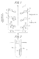
- FIG. 1 is a developed view illustrating a tread pattern of a tire according to one embodiment of the present invention.
- the tread pattern is a directional pattern specifying a tire rotation direction.
- a direction indicated by an arrow with a description "specified tire rotation direction” is the direction specified as the tire rotation direction (a stepping side).
- the tire according to the present invention has at least one lateral groove 2 on a tread surface 1 of the tire extending from a tread end TE to a position which is, relative to the width direction, the inside of a widthwise midpoint P (what is called a 1/4 point) of a tread half having the tread end.
- the tire has six lateral grooves 2 in total; three lateral grooves 2 in each of tread widthwise halves (from a tire equator to one of the tread ends).
- a groove wall 2a on a kicking-out side of at least one of the lateral grooves 2 has a protruding portion 2c protruding toward a groove wall 2b on a stepping side.
- the groove walls 2a on the kicking-out side of the lateral grooves 2 have the protruding portions 2c in a shape protruding toward the groove walls 2b on the stepping side.
- a point Q represents a midpoint (what is called 3/8 points) in the tread width direction between the tread end TE and the widthwise midpoint P of the tread half described above.
- the protruding portion 2c extends in the width direction from a position between the point P and the point Q to the inside of the point P in the width direction.
- At least one of the lateral grooves 2 has a narrow portion in an area in the width direction where the protruding portion 2c extends. Namely, a width of the lateral groove in the area where the protruding portion 2c extends is narrower than that in an area where the protruding portion 2c does not extend.
- the groove wall on the kicking-out side of at least one of the lateral grooves has the protruding portion protruding toward the groove wall on the stepping side and, with reference to the point Q representing the midpoint in the tread width direction between the tread end and the widthwise midpoint P, the protruding portion extends in the tread width direction from the position between the point P and the point Q to the inside of the point P in the width direction.
- specifying the rotation direction of the tire allows separate consideration of the stepping side and the kicking-out side.
- a ground contact surface circumferentially slips in a large amount on the tread surface of a land part divided by the stepping side of the lateral groove. Accordingly, by providing the protruding portion at the above position and closing the lateral groove at the time of contact to the ground, the circumferential slip in the land part at the time of kicking-out described above may be suppressed. Thereby, abrasion resistance of the tire may be improved.
- the protruding portion is provided in the area of the width direction described above, abrasion near a 1/4 point where severe wearing occurs may be suppressed.
- FIG. 2 is a cross-sectional view taken along line A-A in FIG. 1 .
- FIG. 2 illustrates shapes of the lateral groove and the protruding portion when the tire is mounted on a prescribed rim and filled with the air to have a prescribed internal pressure under no load.
- a wall surface 2d of the protruding portion described above is preferably parallel in the cross section to the wall surface 2 on the stepping side of the lateral groove 2.
- a groove bottom is preferably formed such that the protruding portion 2d and the groove bottom smoothly join to each other.
- the "prescribed rim” is a rim defined in the JATMA YEAR BOOK 2008 published by Japan Automobile Tire Manufacturers Association
- the "prescribed internal pressure” is an air pressure corresponding to the maximum load capacity (maximum load) defined in JATMA Year Book 2008.
- the internal pressure represents an air pressure corresponding to the maximum load (maximum load capacity) of a single wheel defined in the standards mentioned below
- the rim represents a standard rim (or "Approved Rim” or "Recommended Rim”) in an applicable size defined in the standards mentioned below.
- Standards are defined according to industrial standards in each area. These standards include, for example, those as defined in the TRY YEAR BOOK published by The Tire and Rim Association Inc . for the United States, or in the ETRTO STANDARD MANUAL published by The European Tire and Rim Technical Organization for European countries .
- a minimum distance d (mm) between the wall surface 2d of the protruding portion described above and the wall surface 2b on the stepping side of the lateral groove 2 is preferably 15% to 30% of a width W (mm) of the lateral groove.
- a tread width 2L (mm) represents a linear distance in the width direction between two tread ends when the tire is mounted on the prescribed rim having the prescribed internal pressure under no load.
- the protruding portion is preferably provided in the width direction across a predetermined area including a midpoint of the tread halves and, particularly preferably, across an area of at least 40% to 60% of a tread half width L (mm) from a tire equatorial plane CL.
- the protruding portion provided in the above area may further ensure to reduce abrasion near the 1/4 point where the tire circumferentially slips in a great amount.
- the protruding portion is preferably provided across an area of at least 80% to 100% of a depth H (mm) of the lateral groove.
- the depth of the lateral groove represents a depth at a position where a tread wear indicator is provided.
- the protruding portion provided in the area is highly effective in suppressing the circumferential slip at the time of kicking-out of the land part divided by the stepping side of the lateral groove.
- the lateral groove 2 preferably inclines to a side of the specified tire rotation direction from the tread end toward the inside in the tread width direction.
- an inclination angle ⁇ of the lateral groove mentioned above is preferably 5° to 45° relative to the tread width direction.
- an internal end portion of the lateral groove in the tread width direction is preferably positioned at the inside of, in the width direction, a position at 0.4 L (mm) from the tire equatorial plane CL outwardly in the tread width direction.
- the protruding portion is preferably provided, in the width direction, across the area of at least 40% to 60% of the tread half L (mm) from the tire equatorial plane CL. Accordingly, in order to provide the protruding portion in the area, the lateral groove preferably extends to the inside of the position at 0.4 L (mm) outside in the tread width direction from the tire equatorial plane CL.
- the lateral groove is preferably orthogonal to the tread end TE.
- the groove bottom of the lateral groove may have a large curvature, suppressing generation of cracks from the groove bottom.
- a circumferential groove 3 that extends in the tread circumferential direction on the tire equatorial plane CL and, further, at least one lateral groove 3a that extends from the circumferential groove 3 outwardly in the tread width direction and remains within the tread surface 1.
- the air flowing through the circumferential groove may be fed to the lateral groove at the time of tire rolling, enabling enhancement of heat dissipation in an entire middle area in the tire width direction where a great amount of heat is generated and improvement in heat generation resistance of the tire.
- the lateral groove preferably extends in an area from a position at 10 mm inside of the point R in the width direction to a position at 10 mm outside of the point R in the width direction.
- the lateral groove when the lateral groove is projected in the tire circumferential direction, the lateral groove preferably overlaps the lateral groove at least partially.
- the lateral groove preferably extends from a position of an outer end of the lateral groove in the tread width direction to the inside of the lateral groove in the tread width direction.
- a length E (mm) of an overlapping portion in the width direction is preferably 20 mm or less, whereby rigidity of the land part may be secured.
- the lateral groove and the lateral groove are preferably parallel to each other, from the point of view of securing the rigidity of the land part.
- the circumferential groove and the lateral groove preferably join to each other at a right angle.
- the tire of the present invention is particularly suitable for a deep-groove tire having a tire diameter of 1.5 mm or more and classified into a tread class E-3 or higher defined by JATMA, TRA and the like.
- tires according to examples 1, 2 of the present invention having a protruding portion on the groove wall on the kicking-out side of the lateral groove that protrudes toward the groove wall on the stepping side were prototyped.
- the term “length of lateral groove” means a length of the lateral groove in the tread width direction.
- the term “angle of lateral groove” means a tilt angle of the lateral groove relative to the tread width direction.
- protruding portion means a portion protruding from the groove wall on the kicking-out side of the lateral groove toward the groove wall on the stepping side, as described above.
- a depth of the lateral groove of each tire is 68 mm in common.
- Each of the tires described above in size of 46/90R57 was mounted on the prescribed rim, filled with the air to have the prescribed internal pressure, and mounted as a front wheel of a vehicle. Thus, a test for evaluation of the abrasion resistance was conducted.
- a drum test was conducted to run the vehicle having each of the above tires mounted thereon at a speed of 80 km/h for a distance of 30000 km.
- Evaluation of the abrasion resistance is determined by obtaining a remaining amount of the grooves after running the drum as described above, and the abrasion resistance is represented by an index relative to the abrasion resistance of the conventional tire represented by 100. The smaller the index is, the better the abrasion resistance is.
- both of the tires of Examples 1, 2 have abrasion resistance superior to that of the tires of the conventional example and the control example.
Landscapes
- Engineering & Computer Science (AREA)
- Mechanical Engineering (AREA)
- Tires In General (AREA)
Applications Claiming Priority (2)
| Application Number | Priority Date | Filing Date | Title |
|---|---|---|---|
| JP2011156052A JP5759291B2 (ja) | 2011-07-14 | 2011-07-14 | 建設車両用の空気入りラジアルタイヤ |
| PCT/JP2012/004553 WO2013008478A1 (ja) | 2011-07-14 | 2012-07-13 | 空気入りラジアルタイヤ |
Publications (3)
| Publication Number | Publication Date |
|---|---|
| EP2732984A1 true EP2732984A1 (de) | 2014-05-21 |
| EP2732984A4 EP2732984A4 (de) | 2015-03-18 |
| EP2732984B1 EP2732984B1 (de) | 2019-03-06 |
Family
ID=47505781
Family Applications (1)
| Application Number | Title | Priority Date | Filing Date |
|---|---|---|---|
| EP12811699.3A Not-in-force EP2732984B1 (de) | 2011-07-14 | 2012-07-13 | Radialluftreifen |
Country Status (7)
| Country | Link |
|---|---|
| US (1) | US9505270B2 (de) |
| EP (1) | EP2732984B1 (de) |
| JP (1) | JP5759291B2 (de) |
| CN (1) | CN103648803B (de) |
| AU (1) | AU2012281958B2 (de) |
| RU (1) | RU2550059C1 (de) |
| WO (1) | WO2013008478A1 (de) |
Cited By (1)
| Publication number | Priority date | Publication date | Assignee | Title |
|---|---|---|---|---|
| US10576788B2 (en) | 2014-03-20 | 2020-03-03 | Bridgestone Corporation | Tire |
Families Citing this family (3)
| Publication number | Priority date | Publication date | Assignee | Title |
|---|---|---|---|---|
| JP6134585B2 (ja) * | 2013-06-03 | 2017-05-24 | 株式会社ブリヂストン | 建設車両用空気入りタイヤ |
| EP3248812B1 (de) * | 2015-03-23 | 2018-12-12 | Bridgestone Corporation | Reifen |
| CN114771159A (zh) * | 2022-05-31 | 2022-07-22 | 合肥万力轮胎有限公司 | 一种轮胎 |
Family Cites Families (23)
| Publication number | Priority date | Publication date | Assignee | Title |
|---|---|---|---|---|
| BE509610A (de) * | 1951-09-28 | |||
| DE8007151U1 (de) * | 1980-03-15 | 1981-04-16 | Uniroyal Gmbh, 5100 Aachen | Fahrzeugluftreifen |
| JPS5911641B2 (ja) | 1981-07-31 | 1984-03-16 | 三菱製鋼株式会社 | ボンディッド永久磁石粉末とその製造方法 |
| JPS5822301U (ja) * | 1981-08-05 | 1983-02-12 | 海江田 展通 | 低騒音タイヤ |
| JP2644499B2 (ja) * | 1987-07-31 | 1997-08-25 | 株式会社ブリヂストン | 高速用空気入りラジアルタイヤ |
| JP3041128B2 (ja) * | 1992-04-08 | 2000-05-15 | オーツタイヤ株式会社 | タイヤの石噛み込み防止構造 |
| EP0599566B1 (de) | 1992-11-20 | 1996-08-14 | Sumitomo Rubber Industries Limited | Verfahren zur Auswahl eines Laufflächenprofils, der ein Schräglaufen des Fahrzeuges verhindert |
| US5580404A (en) * | 1993-08-30 | 1996-12-03 | The Goodyear Tire & Rubber Company | Tread including tie bars and sipes |
| AT403561B (de) * | 1995-01-25 | 1998-03-25 | Semperit Ag | Fahrzeugreifen |
| JPH10264612A (ja) * | 1997-03-24 | 1998-10-06 | Yokohama Rubber Co Ltd:The | 空気入りラジアルタイヤ |
| USD402245S (en) * | 1997-09-22 | 1998-12-08 | The Goodyear Tire & Rubber Company | Tread for a tire |
| JP3860915B2 (ja) * | 1998-06-16 | 2006-12-20 | 横浜ゴム株式会社 | 乗用車用空気入りラジアルタイヤ |
| JP2001055017A (ja) * | 1999-08-18 | 2001-02-27 | Bridgestone Corp | 空気入りタイヤ |
| US7004216B2 (en) * | 2003-12-11 | 2006-02-28 | The Goodyear Tire & Rubber Company | Tire tread including spaced projections in base of groove |
| JP2006131177A (ja) * | 2004-11-09 | 2006-05-25 | Asmo Co Ltd | ワイパブレードラバー及び車両用ワイパ |
| JP4690064B2 (ja) * | 2005-02-03 | 2011-06-01 | 株式会社ブリヂストン | 空気入りタイヤ |
| JP2007083822A (ja) | 2005-09-21 | 2007-04-05 | Bridgestone Corp | 空気入りタイヤ |
| JP4938316B2 (ja) | 2006-01-20 | 2012-05-23 | 株式会社ブリヂストン | 建設車両用タイヤ |
| JP2008279976A (ja) * | 2007-05-14 | 2008-11-20 | Bridgestone Corp | 建設車両用重荷重空気入りラジアルタイヤ |
| JP5435877B2 (ja) * | 2008-01-31 | 2014-03-05 | 株式会社ブリヂストン | 空気入りタイヤ |
| JP5265212B2 (ja) * | 2008-02-12 | 2013-08-14 | 株式会社ブリヂストン | 重荷重用空気入りラジアルタイヤ |
| JP5435905B2 (ja) * | 2008-07-17 | 2014-03-05 | 株式会社ブリヂストン | タイヤ |
| JP2010095092A (ja) * | 2008-10-15 | 2010-04-30 | Bridgestone Corp | タイヤ |
-
2011
- 2011-07-14 JP JP2011156052A patent/JP5759291B2/ja not_active Expired - Fee Related
-
2012
- 2012-07-13 EP EP12811699.3A patent/EP2732984B1/de not_active Not-in-force
- 2012-07-13 WO PCT/JP2012/004553 patent/WO2013008478A1/ja not_active Ceased
- 2012-07-13 AU AU2012281958A patent/AU2012281958B2/en not_active Ceased
- 2012-07-13 CN CN201280033557.4A patent/CN103648803B/zh not_active Expired - Fee Related
- 2012-07-13 US US14/123,993 patent/US9505270B2/en not_active Expired - Fee Related
- 2012-07-13 RU RU2014105429/11A patent/RU2550059C1/ru active
Cited By (1)
| Publication number | Priority date | Publication date | Assignee | Title |
|---|---|---|---|---|
| US10576788B2 (en) | 2014-03-20 | 2020-03-03 | Bridgestone Corporation | Tire |
Also Published As
| Publication number | Publication date |
|---|---|
| JP2013022967A (ja) | 2013-02-04 |
| RU2550059C1 (ru) | 2015-05-10 |
| US20140110026A1 (en) | 2014-04-24 |
| EP2732984A4 (de) | 2015-03-18 |
| AU2012281958B2 (en) | 2016-07-14 |
| JP5759291B2 (ja) | 2015-08-05 |
| AU2012281958A1 (en) | 2014-01-09 |
| US9505270B2 (en) | 2016-11-29 |
| EP2732984B1 (de) | 2019-03-06 |
| CN103648803B (zh) | 2016-02-03 |
| CN103648803A (zh) | 2014-03-19 |
| WO2013008478A1 (ja) | 2013-01-17 |
Similar Documents
| Publication | Publication Date | Title |
|---|---|---|
| EP3715149B1 (de) | Reifen für schwerlastfahrzeug | |
| EP2390113B1 (de) | Reifen | |
| EP2639084A1 (de) | Luftreifen | |
| CN104786745A (zh) | 重载荷用充气轮胎 | |
| WO2014132551A1 (ja) | 乗用車用空気入りラジアルタイヤ | |
| WO2014129571A1 (ja) | タイヤ | |
| EP2732984B1 (de) | Radialluftreifen | |
| CN103029523B (zh) | 重载充气轮胎 | |
| JP5685841B2 (ja) | 空気入りタイヤ | |
| JP6013759B2 (ja) | 空気入りタイヤ | |
| JP4742759B2 (ja) | 空気入りタイヤ | |
| JP4687342B2 (ja) | 空気入りタイヤ | |
| US11964513B2 (en) | Tire | |
| JP2007076594A (ja) | 空気入りタイヤ | |
| US12330452B2 (en) | Tire | |
| JP5739997B2 (ja) | 空気入りタイヤ | |
| JP7342547B2 (ja) | 重荷重用空気入りタイヤ | |
| JP4388309B2 (ja) | 重荷重用タイヤ | |
| JP4363902B2 (ja) | 重荷重用タイヤ | |
| JP7283014B2 (ja) | 空気入りタイヤ | |
| JP2014136444A (ja) | タイヤ | |
| JP2007253816A (ja) | 空気入りラジアルタイヤ | |
| JP2008296799A (ja) | 空気入りタイヤ | |
| JP2014218195A (ja) | 空気入りタイヤ |
Legal Events
| Date | Code | Title | Description |
|---|---|---|---|
| PUAI | Public reference made under article 153(3) epc to a published international application that has entered the european phase |
Free format text: ORIGINAL CODE: 0009012 |
|
| 17P | Request for examination filed |
Effective date: 20131216 |
|
| AK | Designated contracting states |
Kind code of ref document: A1 Designated state(s): AL AT BE BG CH CY CZ DE DK EE ES FI FR GB GR HR HU IE IS IT LI LT LU LV MC MK MT NL NO PL PT RO RS SE SI SK SM TR |
|
| DAX | Request for extension of the european patent (deleted) | ||
| A4 | Supplementary search report drawn up and despatched |
Effective date: 20150217 |
|
| RIC1 | Information provided on ipc code assigned before grant |
Ipc: B60C 11/117 20060101ALI20150211BHEP Ipc: B60C 11/04 20060101AFI20150211BHEP Ipc: B60C 11/13 20060101ALI20150211BHEP |
|
| STAA | Information on the status of an ep patent application or granted ep patent |
Free format text: STATUS: EXAMINATION IS IN PROGRESS |
|
| 17Q | First examination report despatched |
Effective date: 20161216 |
|
| RIC1 | Information provided on ipc code assigned before grant |
Ipc: B60C 11/117 20060101ALI20180716BHEP Ipc: B60C 11/03 20060101ALI20180716BHEP Ipc: B60C 11/04 20060101AFI20180716BHEP Ipc: B60C 11/13 20060101ALI20180716BHEP |
|
| GRAP | Despatch of communication of intention to grant a patent |
Free format text: ORIGINAL CODE: EPIDOSNIGR1 |
|
| STAA | Information on the status of an ep patent application or granted ep patent |
Free format text: STATUS: GRANT OF PATENT IS INTENDED |
|
| RAP1 | Party data changed (applicant data changed or rights of an application transferred) |
Owner name: BRIDGESTONE CORPORATION |
|
| INTG | Intention to grant announced |
Effective date: 20181011 |
|
| GRAS | Grant fee paid |
Free format text: ORIGINAL CODE: EPIDOSNIGR3 |
|
| GRAA | (expected) grant |
Free format text: ORIGINAL CODE: 0009210 |
|
| STAA | Information on the status of an ep patent application or granted ep patent |
Free format text: STATUS: THE PATENT HAS BEEN GRANTED |
|
| AK | Designated contracting states |
Kind code of ref document: B1 Designated state(s): AL AT BE BG CH CY CZ DE DK EE ES FI FR GB GR HR HU IE IS IT LI LT LU LV MC MK MT NL NO PL PT RO RS SE SI SK SM TR |
|
| REG | Reference to a national code |
Ref country code: GB Ref legal event code: FG4D |
|
| REG | Reference to a national code |
Ref country code: CH Ref legal event code: EP Ref country code: AT Ref legal event code: REF Ref document number: 1104045 Country of ref document: AT Kind code of ref document: T Effective date: 20190315 |
|
| REG | Reference to a national code |
Ref country code: DE Ref legal event code: R096 Ref document number: 602012057527 Country of ref document: DE |
|
| REG | Reference to a national code |
Ref country code: IE Ref legal event code: FG4D |
|
| REG | Reference to a national code |
Ref country code: NL Ref legal event code: MP Effective date: 20190306 |
|
| REG | Reference to a national code |
Ref country code: LT Ref legal event code: MG4D |
|
| PG25 | Lapsed in a contracting state [announced via postgrant information from national office to epo] |
Ref country code: SE Free format text: LAPSE BECAUSE OF FAILURE TO SUBMIT A TRANSLATION OF THE DESCRIPTION OR TO PAY THE FEE WITHIN THE PRESCRIBED TIME-LIMIT Effective date: 20190306 Ref country code: LT Free format text: LAPSE BECAUSE OF FAILURE TO SUBMIT A TRANSLATION OF THE DESCRIPTION OR TO PAY THE FEE WITHIN THE PRESCRIBED TIME-LIMIT Effective date: 20190306 Ref country code: FI Free format text: LAPSE BECAUSE OF FAILURE TO SUBMIT A TRANSLATION OF THE DESCRIPTION OR TO PAY THE FEE WITHIN THE PRESCRIBED TIME-LIMIT Effective date: 20190306 Ref country code: NO Free format text: LAPSE BECAUSE OF FAILURE TO SUBMIT A TRANSLATION OF THE DESCRIPTION OR TO PAY THE FEE WITHIN THE PRESCRIBED TIME-LIMIT Effective date: 20190606 |
|
| PG25 | Lapsed in a contracting state [announced via postgrant information from national office to epo] |
Ref country code: LV Free format text: LAPSE BECAUSE OF FAILURE TO SUBMIT A TRANSLATION OF THE DESCRIPTION OR TO PAY THE FEE WITHIN THE PRESCRIBED TIME-LIMIT Effective date: 20190306 Ref country code: GR Free format text: LAPSE BECAUSE OF FAILURE TO SUBMIT A TRANSLATION OF THE DESCRIPTION OR TO PAY THE FEE WITHIN THE PRESCRIBED TIME-LIMIT Effective date: 20190607 Ref country code: HR Free format text: LAPSE BECAUSE OF FAILURE TO SUBMIT A TRANSLATION OF THE DESCRIPTION OR TO PAY THE FEE WITHIN THE PRESCRIBED TIME-LIMIT Effective date: 20190306 Ref country code: NL Free format text: LAPSE BECAUSE OF FAILURE TO SUBMIT A TRANSLATION OF THE DESCRIPTION OR TO PAY THE FEE WITHIN THE PRESCRIBED TIME-LIMIT Effective date: 20190306 Ref country code: RS Free format text: LAPSE BECAUSE OF FAILURE TO SUBMIT A TRANSLATION OF THE DESCRIPTION OR TO PAY THE FEE WITHIN THE PRESCRIBED TIME-LIMIT Effective date: 20190306 Ref country code: BG Free format text: LAPSE BECAUSE OF FAILURE TO SUBMIT A TRANSLATION OF THE DESCRIPTION OR TO PAY THE FEE WITHIN THE PRESCRIBED TIME-LIMIT Effective date: 20190606 |
|
| REG | Reference to a national code |
Ref country code: AT Ref legal event code: MK05 Ref document number: 1104045 Country of ref document: AT Kind code of ref document: T Effective date: 20190306 |
|
| PG25 | Lapsed in a contracting state [announced via postgrant information from national office to epo] |
Ref country code: PT Free format text: LAPSE BECAUSE OF FAILURE TO SUBMIT A TRANSLATION OF THE DESCRIPTION OR TO PAY THE FEE WITHIN THE PRESCRIBED TIME-LIMIT Effective date: 20190706 Ref country code: AL Free format text: LAPSE BECAUSE OF FAILURE TO SUBMIT A TRANSLATION OF THE DESCRIPTION OR TO PAY THE FEE WITHIN THE PRESCRIBED TIME-LIMIT Effective date: 20190306 Ref country code: RO Free format text: LAPSE BECAUSE OF FAILURE TO SUBMIT A TRANSLATION OF THE DESCRIPTION OR TO PAY THE FEE WITHIN THE PRESCRIBED TIME-LIMIT Effective date: 20190306 Ref country code: CZ Free format text: LAPSE BECAUSE OF FAILURE TO SUBMIT A TRANSLATION OF THE DESCRIPTION OR TO PAY THE FEE WITHIN THE PRESCRIBED TIME-LIMIT Effective date: 20190306 Ref country code: ES Free format text: LAPSE BECAUSE OF FAILURE TO SUBMIT A TRANSLATION OF THE DESCRIPTION OR TO PAY THE FEE WITHIN THE PRESCRIBED TIME-LIMIT Effective date: 20190306 Ref country code: EE Free format text: LAPSE BECAUSE OF FAILURE TO SUBMIT A TRANSLATION OF THE DESCRIPTION OR TO PAY THE FEE WITHIN THE PRESCRIBED TIME-LIMIT Effective date: 20190306 Ref country code: IT Free format text: LAPSE BECAUSE OF FAILURE TO SUBMIT A TRANSLATION OF THE DESCRIPTION OR TO PAY THE FEE WITHIN THE PRESCRIBED TIME-LIMIT Effective date: 20190306 Ref country code: SK Free format text: LAPSE BECAUSE OF FAILURE TO SUBMIT A TRANSLATION OF THE DESCRIPTION OR TO PAY THE FEE WITHIN THE PRESCRIBED TIME-LIMIT Effective date: 20190306 |
|
| PG25 | Lapsed in a contracting state [announced via postgrant information from national office to epo] |
Ref country code: PL Free format text: LAPSE BECAUSE OF FAILURE TO SUBMIT A TRANSLATION OF THE DESCRIPTION OR TO PAY THE FEE WITHIN THE PRESCRIBED TIME-LIMIT Effective date: 20190306 Ref country code: SM Free format text: LAPSE BECAUSE OF FAILURE TO SUBMIT A TRANSLATION OF THE DESCRIPTION OR TO PAY THE FEE WITHIN THE PRESCRIBED TIME-LIMIT Effective date: 20190306 |
|
| REG | Reference to a national code |
Ref country code: DE Ref legal event code: R097 Ref document number: 602012057527 Country of ref document: DE |
|
| PG25 | Lapsed in a contracting state [announced via postgrant information from national office to epo] |
Ref country code: IS Free format text: LAPSE BECAUSE OF FAILURE TO SUBMIT A TRANSLATION OF THE DESCRIPTION OR TO PAY THE FEE WITHIN THE PRESCRIBED TIME-LIMIT Effective date: 20190706 Ref country code: AT Free format text: LAPSE BECAUSE OF FAILURE TO SUBMIT A TRANSLATION OF THE DESCRIPTION OR TO PAY THE FEE WITHIN THE PRESCRIBED TIME-LIMIT Effective date: 20190306 |
|
| PLBE | No opposition filed within time limit |
Free format text: ORIGINAL CODE: 0009261 |
|
| STAA | Information on the status of an ep patent application or granted ep patent |
Free format text: STATUS: NO OPPOSITION FILED WITHIN TIME LIMIT |
|
| PG25 | Lapsed in a contracting state [announced via postgrant information from national office to epo] |
Ref country code: DK Free format text: LAPSE BECAUSE OF FAILURE TO SUBMIT A TRANSLATION OF THE DESCRIPTION OR TO PAY THE FEE WITHIN THE PRESCRIBED TIME-LIMIT Effective date: 20190306 |
|
| 26N | No opposition filed |
Effective date: 20191209 |
|
| PG25 | Lapsed in a contracting state [announced via postgrant information from national office to epo] |
Ref country code: MC Free format text: LAPSE BECAUSE OF FAILURE TO SUBMIT A TRANSLATION OF THE DESCRIPTION OR TO PAY THE FEE WITHIN THE PRESCRIBED TIME-LIMIT Effective date: 20190306 Ref country code: SI Free format text: LAPSE BECAUSE OF FAILURE TO SUBMIT A TRANSLATION OF THE DESCRIPTION OR TO PAY THE FEE WITHIN THE PRESCRIBED TIME-LIMIT Effective date: 20190306 |
|
| REG | Reference to a national code |
Ref country code: CH Ref legal event code: PL |
|
| GBPC | Gb: european patent ceased through non-payment of renewal fee |
Effective date: 20190713 |
|
| PG25 | Lapsed in a contracting state [announced via postgrant information from national office to epo] |
Ref country code: TR Free format text: LAPSE BECAUSE OF FAILURE TO SUBMIT A TRANSLATION OF THE DESCRIPTION OR TO PAY THE FEE WITHIN THE PRESCRIBED TIME-LIMIT Effective date: 20190306 |
|
| REG | Reference to a national code |
Ref country code: BE Ref legal event code: MM Effective date: 20190731 |
|
| PG25 | Lapsed in a contracting state [announced via postgrant information from national office to epo] |
Ref country code: GB Free format text: LAPSE BECAUSE OF NON-PAYMENT OF DUE FEES Effective date: 20190713 |
|
| PG25 | Lapsed in a contracting state [announced via postgrant information from national office to epo] |
Ref country code: LU Free format text: LAPSE BECAUSE OF NON-PAYMENT OF DUE FEES Effective date: 20190713 Ref country code: BE Free format text: LAPSE BECAUSE OF NON-PAYMENT OF DUE FEES Effective date: 20190731 Ref country code: CH Free format text: LAPSE BECAUSE OF NON-PAYMENT OF DUE FEES Effective date: 20190731 Ref country code: LI Free format text: LAPSE BECAUSE OF NON-PAYMENT OF DUE FEES Effective date: 20190731 |
|
| PG25 | Lapsed in a contracting state [announced via postgrant information from national office to epo] |
Ref country code: IE Free format text: LAPSE BECAUSE OF NON-PAYMENT OF DUE FEES Effective date: 20190713 |
|
| PGFP | Annual fee paid to national office [announced via postgrant information from national office to epo] |
Ref country code: FR Payment date: 20200723 Year of fee payment: 9 Ref country code: DE Payment date: 20200721 Year of fee payment: 9 |
|
| PG25 | Lapsed in a contracting state [announced via postgrant information from national office to epo] |
Ref country code: CY Free format text: LAPSE BECAUSE OF FAILURE TO SUBMIT A TRANSLATION OF THE DESCRIPTION OR TO PAY THE FEE WITHIN THE PRESCRIBED TIME-LIMIT Effective date: 20190306 |
|
| PG25 | Lapsed in a contracting state [announced via postgrant information from national office to epo] |
Ref country code: HU Free format text: LAPSE BECAUSE OF FAILURE TO SUBMIT A TRANSLATION OF THE DESCRIPTION OR TO PAY THE FEE WITHIN THE PRESCRIBED TIME-LIMIT; INVALID AB INITIO Effective date: 20120713 Ref country code: MT Free format text: LAPSE BECAUSE OF FAILURE TO SUBMIT A TRANSLATION OF THE DESCRIPTION OR TO PAY THE FEE WITHIN THE PRESCRIBED TIME-LIMIT Effective date: 20190306 |
|
| REG | Reference to a national code |
Ref country code: DE Ref legal event code: R119 Ref document number: 602012057527 Country of ref document: DE |
|
| PG25 | Lapsed in a contracting state [announced via postgrant information from national office to epo] |
Ref country code: DE Free format text: LAPSE BECAUSE OF NON-PAYMENT OF DUE FEES Effective date: 20220201 |
|
| PG25 | Lapsed in a contracting state [announced via postgrant information from national office to epo] |
Ref country code: FR Free format text: LAPSE BECAUSE OF NON-PAYMENT OF DUE FEES Effective date: 20210731 |
|
| PG25 | Lapsed in a contracting state [announced via postgrant information from national office to epo] |
Ref country code: MK Free format text: LAPSE BECAUSE OF FAILURE TO SUBMIT A TRANSLATION OF THE DESCRIPTION OR TO PAY THE FEE WITHIN THE PRESCRIBED TIME-LIMIT Effective date: 20190306 |