EP2696786B1 - Devices for remote temperature monitoring in fluid enhanced ablation therapy - Google Patents
Devices for remote temperature monitoring in fluid enhanced ablation therapy Download PDFInfo
- Publication number
- EP2696786B1 EP2696786B1 EP12770631.5A EP12770631A EP2696786B1 EP 2696786 B1 EP2696786 B1 EP 2696786B1 EP 12770631 A EP12770631 A EP 12770631A EP 2696786 B1 EP2696786 B1 EP 2696786B1
- Authority
- EP
- European Patent Office
- Prior art keywords
- elongate body
- ablation
- temperature
- tissue
- fluid
- Prior art date
- Legal status (The legal status is an assumption and is not a legal conclusion. Google has not performed a legal analysis and makes no representation as to the accuracy of the status listed.)
- Not-in-force
Links
- 239000012530 fluid Substances 0.000 title claims description 140
- 238000010317 ablation therapy Methods 0.000 title description 20
- 238000012544 monitoring process Methods 0.000 title description 6
- 238000002679 ablation Methods 0.000 claims description 155
- 238000011282 treatment Methods 0.000 claims description 85
- 230000001225 therapeutic effect Effects 0.000 claims description 37
- 238000010438 heat treatment Methods 0.000 claims description 30
- FAPWRFPIFSIZLT-UHFFFAOYSA-M Sodium chloride Chemical compound [Na+].[Cl-] FAPWRFPIFSIZLT-UHFFFAOYSA-M 0.000 claims description 20
- 239000011780 sodium chloride Substances 0.000 claims description 15
- 238000004891 communication Methods 0.000 claims description 4
- 125000006850 spacer group Chemical group 0.000 claims description 4
- 230000004044 response Effects 0.000 claims description 3
- 210000001519 tissue Anatomy 0.000 description 148
- 238000000034 method Methods 0.000 description 40
- 238000002560 therapeutic procedure Methods 0.000 description 21
- 230000003902 lesion Effects 0.000 description 18
- 238000011287 therapeutic dose Methods 0.000 description 14
- 241001631457 Cannula Species 0.000 description 10
- 229910052751 metal Inorganic materials 0.000 description 10
- 239000002184 metal Substances 0.000 description 10
- 239000000463 material Substances 0.000 description 8
- 238000003780 insertion Methods 0.000 description 7
- 230000037431 insertion Effects 0.000 description 7
- 238000005259 measurement Methods 0.000 description 7
- 229910052709 silver Inorganic materials 0.000 description 6
- 239000004332 silver Substances 0.000 description 6
- 229910021607 Silver chloride Inorganic materials 0.000 description 5
- 239000004020 conductor Substances 0.000 description 5
- 239000003814 drug Substances 0.000 description 5
- 229940079593 drug Drugs 0.000 description 5
- 238000005516 engineering process Methods 0.000 description 5
- 239000011810 insulating material Substances 0.000 description 5
- 239000007788 liquid Substances 0.000 description 5
- 239000004033 plastic Substances 0.000 description 5
- 229920003023 plastic Polymers 0.000 description 5
- 108090000623 proteins and genes Proteins 0.000 description 5
- 230000005855 radiation Effects 0.000 description 5
- 150000003839 salts Chemical class 0.000 description 5
- HKZLPVFGJNLROG-UHFFFAOYSA-M silver monochloride Chemical compound [Cl-].[Ag+] HKZLPVFGJNLROG-UHFFFAOYSA-M 0.000 description 5
- 229910001006 Constantan Inorganic materials 0.000 description 4
- 230000003247 decreasing effect Effects 0.000 description 4
- 238000002595 magnetic resonance imaging Methods 0.000 description 4
- 239000010935 stainless steel Substances 0.000 description 4
- 229910001220 stainless steel Inorganic materials 0.000 description 4
- 230000001954 sterilising effect Effects 0.000 description 4
- 238000004659 sterilization and disinfection Methods 0.000 description 4
- 239000013603 viral vector Substances 0.000 description 4
- 206010028980 Neoplasm Diseases 0.000 description 3
- 230000008901 benefit Effects 0.000 description 3
- 238000009529 body temperature measurement Methods 0.000 description 3
- 210000004027 cell Anatomy 0.000 description 3
- 238000004140 cleaning Methods 0.000 description 3
- 230000006378 damage Effects 0.000 description 3
- 238000002059 diagnostic imaging Methods 0.000 description 3
- 238000010586 diagram Methods 0.000 description 3
- 230000000694 effects Effects 0.000 description 3
- 238000003384 imaging method Methods 0.000 description 3
- 238000002955 isolation Methods 0.000 description 3
- 230000007246 mechanism Effects 0.000 description 3
- 230000017074 necrotic cell death Effects 0.000 description 3
- 229910001000 nickel titanium Inorganic materials 0.000 description 3
- 229920000642 polymer Polymers 0.000 description 3
- 238000007674 radiofrequency ablation Methods 0.000 description 3
- 238000007493 shaping process Methods 0.000 description 3
- 238000001356 surgical procedure Methods 0.000 description 3
- 206010047302 ventricular tachycardia Diseases 0.000 description 3
- 239000004593 Epoxy Substances 0.000 description 2
- IAYPIBMASNFSPL-UHFFFAOYSA-N Ethylene oxide Chemical compound C1CO1 IAYPIBMASNFSPL-UHFFFAOYSA-N 0.000 description 2
- 206010003119 arrhythmia Diseases 0.000 description 2
- 230000036760 body temperature Effects 0.000 description 2
- 229910001179 chromel Inorganic materials 0.000 description 2
- 238000010276 construction Methods 0.000 description 2
- 230000001276 controlling effect Effects 0.000 description 2
- 230000001419 dependent effect Effects 0.000 description 2
- 238000011161 development Methods 0.000 description 2
- HLXZNVUGXRDIFK-UHFFFAOYSA-N nickel titanium Chemical compound [Ti].[Ti].[Ti].[Ti].[Ti].[Ti].[Ti].[Ti].[Ti].[Ti].[Ti].[Ni].[Ni].[Ni].[Ni].[Ni].[Ni].[Ni].[Ni].[Ni].[Ni].[Ni].[Ni].[Ni].[Ni] HLXZNVUGXRDIFK-UHFFFAOYSA-N 0.000 description 2
- 230000021715 photosynthesis, light harvesting Effects 0.000 description 2
- BASFCYQUMIYNBI-UHFFFAOYSA-N platinum Chemical compound [Pt] BASFCYQUMIYNBI-UHFFFAOYSA-N 0.000 description 2
- 230000001105 regulatory effect Effects 0.000 description 2
- 239000000523 sample Substances 0.000 description 2
- 239000007787 solid Substances 0.000 description 2
- 238000002604 ultrasonography Methods 0.000 description 2
- XLYOFNOQVPJJNP-UHFFFAOYSA-N water Substances O XLYOFNOQVPJJNP-UHFFFAOYSA-N 0.000 description 2
- 241000894006 Bacteria Species 0.000 description 1
- 229910000570 Cupronickel Inorganic materials 0.000 description 1
- 206010020843 Hyperthermia Diseases 0.000 description 1
- 239000004642 Polyimide Substances 0.000 description 1
- BQCADISMDOOEFD-UHFFFAOYSA-N Silver Chemical compound [Ag] BQCADISMDOOEFD-UHFFFAOYSA-N 0.000 description 1
- 239000004775 Tyvek Substances 0.000 description 1
- 229920000690 Tyvek Polymers 0.000 description 1
- 206010046798 Uterine leiomyoma Diseases 0.000 description 1
- 238000011298 ablation treatment Methods 0.000 description 1
- 230000004913 activation Effects 0.000 description 1
- 238000011374 additional therapy Methods 0.000 description 1
- 239000000853 adhesive Substances 0.000 description 1
- 230000001070 adhesive effect Effects 0.000 description 1
- 229910045601 alloy Inorganic materials 0.000 description 1
- 239000000956 alloy Substances 0.000 description 1
- 230000004075 alteration Effects 0.000 description 1
- 238000004458 analytical method Methods 0.000 description 1
- 210000004204 blood vessel Anatomy 0.000 description 1
- 238000004364 calculation method Methods 0.000 description 1
- 230000008859 change Effects 0.000 description 1
- 239000011248 coating agent Substances 0.000 description 1
- 238000000576 coating method Methods 0.000 description 1
- 230000003750 conditioning effect Effects 0.000 description 1
- YOCUPQPZWBBYIX-UHFFFAOYSA-N copper nickel Chemical compound [Ni].[Cu] YOCUPQPZWBBYIX-UHFFFAOYSA-N 0.000 description 1
- 230000007423 decrease Effects 0.000 description 1
- 238000013461 design Methods 0.000 description 1
- 238000001514 detection method Methods 0.000 description 1
- 238000009760 electrical discharge machining Methods 0.000 description 1
- 238000002474 experimental method Methods 0.000 description 1
- 210000001723 extracellular space Anatomy 0.000 description 1
- 238000001125 extrusion Methods 0.000 description 1
- 229920002457 flexible plastic Polymers 0.000 description 1
- 229920002313 fluoropolymer Polymers 0.000 description 1
- 239000004811 fluoropolymer Substances 0.000 description 1
- 230000006870 function Effects 0.000 description 1
- PCHJSUWPFVWCPO-UHFFFAOYSA-N gold Chemical compound [Au] PCHJSUWPFVWCPO-UHFFFAOYSA-N 0.000 description 1
- 229910052737 gold Inorganic materials 0.000 description 1
- 239000010931 gold Substances 0.000 description 1
- 238000009499 grossing Methods 0.000 description 1
- 230000036031 hyperthermia Effects 0.000 description 1
- 230000006872 improvement Effects 0.000 description 1
- 208000015181 infectious disease Diseases 0.000 description 1
- 238000011221 initial treatment Methods 0.000 description 1
- 238000009413 insulation Methods 0.000 description 1
- 230000002427 irreversible effect Effects 0.000 description 1
- 201000010260 leiomyoma Diseases 0.000 description 1
- 238000004519 manufacturing process Methods 0.000 description 1
- 150000002739 metals Chemical class 0.000 description 1
- 238000002324 minimally invasive surgery Methods 0.000 description 1
- 239000000203 mixture Substances 0.000 description 1
- 238000012986 modification Methods 0.000 description 1
- 230000004048 modification Effects 0.000 description 1
- 229910000623 nickel–chromium alloy Inorganic materials 0.000 description 1
- 239000012811 non-conductive material Substances 0.000 description 1
- 238000002355 open surgical procedure Methods 0.000 description 1
- 230000010412 perfusion Effects 0.000 description 1
- 230000000704 physical effect Effects 0.000 description 1
- 229910052697 platinum Inorganic materials 0.000 description 1
- 229920001721 polyimide Polymers 0.000 description 1
- 230000008569 process Effects 0.000 description 1
- 238000012545 processing Methods 0.000 description 1
- 238000007789 sealing Methods 0.000 description 1
- 238000000926 separation method Methods 0.000 description 1
- 230000002123 temporal effect Effects 0.000 description 1
- 238000012360 testing method Methods 0.000 description 1
- 230000003685 thermal hair damage Effects 0.000 description 1
- 238000012546 transfer Methods 0.000 description 1
- 238000009834 vaporization Methods 0.000 description 1
- 230000008016 vaporization Effects 0.000 description 1
- 238000003466 welding Methods 0.000 description 1
Images


Classifications
-
- A—HUMAN NECESSITIES
- A61—MEDICAL OR VETERINARY SCIENCE; HYGIENE
- A61B—DIAGNOSIS; SURGERY; IDENTIFICATION
- A61B18/00—Surgical instruments, devices or methods for transferring non-mechanical forms of energy to or from the body
- A61B18/04—Surgical instruments, devices or methods for transferring non-mechanical forms of energy to or from the body by heating
- A61B18/08—Surgical instruments, devices or methods for transferring non-mechanical forms of energy to or from the body by heating by means of electrically-heated probes
- A61B18/082—Probes or electrodes therefor
-
- A—HUMAN NECESSITIES
- A61—MEDICAL OR VETERINARY SCIENCE; HYGIENE
- A61B—DIAGNOSIS; SURGERY; IDENTIFICATION
- A61B17/00—Surgical instruments, devices or methods
- A61B17/32—Surgical cutting instruments
- A61B17/3203—Fluid jet cutting instruments
-
- A—HUMAN NECESSITIES
- A61—MEDICAL OR VETERINARY SCIENCE; HYGIENE
- A61B—DIAGNOSIS; SURGERY; IDENTIFICATION
- A61B18/00—Surgical instruments, devices or methods for transferring non-mechanical forms of energy to or from the body
- A61B18/04—Surgical instruments, devices or methods for transferring non-mechanical forms of energy to or from the body by heating
- A61B18/12—Surgical instruments, devices or methods for transferring non-mechanical forms of energy to or from the body by heating by passing a current through the tissue to be heated, e.g. high-frequency current
- A61B18/14—Probes or electrodes therefor
- A61B18/1477—Needle-like probes
-
- A—HUMAN NECESSITIES
- A61—MEDICAL OR VETERINARY SCIENCE; HYGIENE
- A61B—DIAGNOSIS; SURGERY; IDENTIFICATION
- A61B18/00—Surgical instruments, devices or methods for transferring non-mechanical forms of energy to or from the body
- A61B18/04—Surgical instruments, devices or methods for transferring non-mechanical forms of energy to or from the body by heating
- A61B18/12—Surgical instruments, devices or methods for transferring non-mechanical forms of energy to or from the body by heating by passing a current through the tissue to be heated, e.g. high-frequency current
- A61B18/14—Probes or electrodes therefor
- A61B18/16—Indifferent or passive electrodes for grounding
-
- F—MECHANICAL ENGINEERING; LIGHTING; HEATING; WEAPONS; BLASTING
- F04—POSITIVE - DISPLACEMENT MACHINES FOR LIQUIDS; PUMPS FOR LIQUIDS OR ELASTIC FLUIDS
- F04B—POSITIVE-DISPLACEMENT MACHINES FOR LIQUIDS; PUMPS
- F04B17/00—Pumps characterised by combination with, or adaptation to, specific driving engines or motors
- F04B17/03—Pumps characterised by combination with, or adaptation to, specific driving engines or motors driven by electric motors
-
- F—MECHANICAL ENGINEERING; LIGHTING; HEATING; WEAPONS; BLASTING
- F04—POSITIVE - DISPLACEMENT MACHINES FOR LIQUIDS; PUMPS FOR LIQUIDS OR ELASTIC FLUIDS
- F04B—POSITIVE-DISPLACEMENT MACHINES FOR LIQUIDS; PUMPS
- F04B41/00—Pumping installations or systems specially adapted for elastic fluids
- F04B41/02—Pumping installations or systems specially adapted for elastic fluids having reservoirs
-
- A—HUMAN NECESSITIES
- A61—MEDICAL OR VETERINARY SCIENCE; HYGIENE
- A61B—DIAGNOSIS; SURGERY; IDENTIFICATION
- A61B17/00—Surgical instruments, devices or methods
- A61B2017/00526—Methods of manufacturing
-
- A—HUMAN NECESSITIES
- A61—MEDICAL OR VETERINARY SCIENCE; HYGIENE
- A61B—DIAGNOSIS; SURGERY; IDENTIFICATION
- A61B18/00—Surgical instruments, devices or methods for transferring non-mechanical forms of energy to or from the body
- A61B2018/00005—Cooling or heating of the probe or tissue immediately surrounding the probe
- A61B2018/00011—Cooling or heating of the probe or tissue immediately surrounding the probe with fluids
- A61B2018/00029—Cooling or heating of the probe or tissue immediately surrounding the probe with fluids open
-
- A—HUMAN NECESSITIES
- A61—MEDICAL OR VETERINARY SCIENCE; HYGIENE
- A61B—DIAGNOSIS; SURGERY; IDENTIFICATION
- A61B18/00—Surgical instruments, devices or methods for transferring non-mechanical forms of energy to or from the body
- A61B2018/00005—Cooling or heating of the probe or tissue immediately surrounding the probe
- A61B2018/00041—Heating, e.g. defrosting
-
- A—HUMAN NECESSITIES
- A61—MEDICAL OR VETERINARY SCIENCE; HYGIENE
- A61B—DIAGNOSIS; SURGERY; IDENTIFICATION
- A61B18/00—Surgical instruments, devices or methods for transferring non-mechanical forms of energy to or from the body
- A61B2018/00571—Surgical instruments, devices or methods for transferring non-mechanical forms of energy to or from the body for achieving a particular surgical effect
- A61B2018/00577—Ablation
-
- A—HUMAN NECESSITIES
- A61—MEDICAL OR VETERINARY SCIENCE; HYGIENE
- A61B—DIAGNOSIS; SURGERY; IDENTIFICATION
- A61B18/00—Surgical instruments, devices or methods for transferring non-mechanical forms of energy to or from the body
- A61B2018/00636—Sensing and controlling the application of energy
- A61B2018/00642—Sensing and controlling the application of energy with feedback, i.e. closed loop control
-
- A—HUMAN NECESSITIES
- A61—MEDICAL OR VETERINARY SCIENCE; HYGIENE
- A61B—DIAGNOSIS; SURGERY; IDENTIFICATION
- A61B18/00—Surgical instruments, devices or methods for transferring non-mechanical forms of energy to or from the body
- A61B2018/00636—Sensing and controlling the application of energy
- A61B2018/00696—Controlled or regulated parameters
- A61B2018/00744—Fluid flow
-
- A—HUMAN NECESSITIES
- A61—MEDICAL OR VETERINARY SCIENCE; HYGIENE
- A61B—DIAGNOSIS; SURGERY; IDENTIFICATION
- A61B18/00—Surgical instruments, devices or methods for transferring non-mechanical forms of energy to or from the body
- A61B2018/00636—Sensing and controlling the application of energy
- A61B2018/00773—Sensed parameters
- A61B2018/00791—Temperature
- A61B2018/00797—Temperature measured by multiple temperature sensors
-
- A—HUMAN NECESSITIES
- A61—MEDICAL OR VETERINARY SCIENCE; HYGIENE
- A61B—DIAGNOSIS; SURGERY; IDENTIFICATION
- A61B18/00—Surgical instruments, devices or methods for transferring non-mechanical forms of energy to or from the body
- A61B2018/00636—Sensing and controlling the application of energy
- A61B2018/00773—Sensed parameters
- A61B2018/00791—Temperature
- A61B2018/00809—Temperature measured thermochromatically
-
- A—HUMAN NECESSITIES
- A61—MEDICAL OR VETERINARY SCIENCE; HYGIENE
- A61B—DIAGNOSIS; SURGERY; IDENTIFICATION
- A61B18/00—Surgical instruments, devices or methods for transferring non-mechanical forms of energy to or from the body
- A61B2018/00636—Sensing and controlling the application of energy
- A61B2018/00773—Sensed parameters
- A61B2018/00791—Temperature
- A61B2018/00821—Temperature measured by a thermocouple
-
- A—HUMAN NECESSITIES
- A61—MEDICAL OR VETERINARY SCIENCE; HYGIENE
- A61B—DIAGNOSIS; SURGERY; IDENTIFICATION
- A61B18/00—Surgical instruments, devices or methods for transferring non-mechanical forms of energy to or from the body
- A61B18/04—Surgical instruments, devices or methods for transferring non-mechanical forms of energy to or from the body by heating
- A61B2018/044—Surgical instruments, devices or methods for transferring non-mechanical forms of energy to or from the body by heating the surgical action being effected by a circulating hot fluid
- A61B2018/046—Surgical instruments, devices or methods for transferring non-mechanical forms of energy to or from the body by heating the surgical action being effected by a circulating hot fluid in liquid form
-
- A—HUMAN NECESSITIES
- A61—MEDICAL OR VETERINARY SCIENCE; HYGIENE
- A61B—DIAGNOSIS; SURGERY; IDENTIFICATION
- A61B18/00—Surgical instruments, devices or methods for transferring non-mechanical forms of energy to or from the body
- A61B18/04—Surgical instruments, devices or methods for transferring non-mechanical forms of energy to or from the body by heating
- A61B18/12—Surgical instruments, devices or methods for transferring non-mechanical forms of energy to or from the body by heating by passing a current through the tissue to be heated, e.g. high-frequency current
- A61B18/14—Probes or electrodes therefor
- A61B2018/1405—Electrodes having a specific shape
- A61B2018/1425—Needle
-
- A—HUMAN NECESSITIES
- A61—MEDICAL OR VETERINARY SCIENCE; HYGIENE
- A61B—DIAGNOSIS; SURGERY; IDENTIFICATION
- A61B18/00—Surgical instruments, devices or methods for transferring non-mechanical forms of energy to or from the body
- A61B18/04—Surgical instruments, devices or methods for transferring non-mechanical forms of energy to or from the body by heating
- A61B18/12—Surgical instruments, devices or methods for transferring non-mechanical forms of energy to or from the body by heating by passing a current through the tissue to be heated, e.g. high-frequency current
- A61B18/14—Probes or electrodes therefor
- A61B2018/1472—Probes or electrodes therefor for use with liquid electrolyte, e.g. virtual electrodes
-
- A—HUMAN NECESSITIES
- A61—MEDICAL OR VETERINARY SCIENCE; HYGIENE
- A61B—DIAGNOSIS; SURGERY; IDENTIFICATION
- A61B18/00—Surgical instruments, devices or methods for transferring non-mechanical forms of energy to or from the body
- A61B18/04—Surgical instruments, devices or methods for transferring non-mechanical forms of energy to or from the body by heating
- A61B18/12—Surgical instruments, devices or methods for transferring non-mechanical forms of energy to or from the body by heating by passing a current through the tissue to be heated, e.g. high-frequency current
- A61B18/14—Probes or electrodes therefor
- A61B18/16—Indifferent or passive electrodes for grounding
- A61B2018/162—Indifferent or passive electrodes for grounding located on the probe body
-
- F—MECHANICAL ENGINEERING; LIGHTING; HEATING; WEAPONS; BLASTING
- F04—POSITIVE - DISPLACEMENT MACHINES FOR LIQUIDS; PUMPS FOR LIQUIDS OR ELASTIC FLUIDS
- F04B—POSITIVE-DISPLACEMENT MACHINES FOR LIQUIDS; PUMPS
- F04B19/00—Machines or pumps having pertinent characteristics not provided for in, or of interest apart from, groups F04B1/00 - F04B17/00
- F04B19/20—Other positive-displacement pumps
- F04B19/22—Other positive-displacement pumps of reciprocating-piston type
-
- F—MECHANICAL ENGINEERING; LIGHTING; HEATING; WEAPONS; BLASTING
- F04—POSITIVE - DISPLACEMENT MACHINES FOR LIQUIDS; PUMPS FOR LIQUIDS OR ELASTIC FLUIDS
- F04B—POSITIVE-DISPLACEMENT MACHINES FOR LIQUIDS; PUMPS
- F04B43/00—Machines, pumps, or pumping installations having flexible working members
- F04B43/02—Machines, pumps, or pumping installations having flexible working members having plate-like flexible members, e.g. diaphragms
- F04B43/04—Pumps having electric drive
-
- F—MECHANICAL ENGINEERING; LIGHTING; HEATING; WEAPONS; BLASTING
- F04—POSITIVE - DISPLACEMENT MACHINES FOR LIQUIDS; PUMPS FOR LIQUIDS OR ELASTIC FLUIDS
- F04B—POSITIVE-DISPLACEMENT MACHINES FOR LIQUIDS; PUMPS
- F04B49/00—Control, e.g. of pump delivery, or pump pressure of, or safety measures for, machines, pumps, or pumping installations, not otherwise provided for, or of interest apart from, groups F04B1/00 - F04B47/00
- F04B49/06—Control using electricity
-
- F—MECHANICAL ENGINEERING; LIGHTING; HEATING; WEAPONS; BLASTING
- F04—POSITIVE - DISPLACEMENT MACHINES FOR LIQUIDS; PUMPS FOR LIQUIDS OR ELASTIC FLUIDS
- F04C—ROTARY-PISTON, OR OSCILLATING-PISTON, POSITIVE-DISPLACEMENT MACHINES FOR LIQUIDS; ROTARY-PISTON, OR OSCILLATING-PISTON, POSITIVE-DISPLACEMENT PUMPS
- F04C2270/00—Control; Monitoring or safety arrangements
- F04C2270/04—Force
- F04C2270/041—Controlled or regulated
-
- Y—GENERAL TAGGING OF NEW TECHNOLOGICAL DEVELOPMENTS; GENERAL TAGGING OF CROSS-SECTIONAL TECHNOLOGIES SPANNING OVER SEVERAL SECTIONS OF THE IPC; TECHNICAL SUBJECTS COVERED BY FORMER USPC CROSS-REFERENCE ART COLLECTIONS [XRACs] AND DIGESTS
- Y10—TECHNICAL SUBJECTS COVERED BY FORMER USPC
- Y10T—TECHNICAL SUBJECTS COVERED BY FORMER US CLASSIFICATION
- Y10T29/00—Metal working
- Y10T29/49—Method of mechanical manufacture
- Y10T29/49002—Electrical device making
- Y10T29/49016—Antenna or wave energy "plumbing" making
-
- Y—GENERAL TAGGING OF NEW TECHNOLOGICAL DEVELOPMENTS; GENERAL TAGGING OF CROSS-SECTIONAL TECHNOLOGIES SPANNING OVER SEVERAL SECTIONS OF THE IPC; TECHNICAL SUBJECTS COVERED BY FORMER USPC CROSS-REFERENCE ART COLLECTIONS [XRACs] AND DIGESTS
- Y10—TECHNICAL SUBJECTS COVERED BY FORMER USPC
- Y10T—TECHNICAL SUBJECTS COVERED BY FORMER US CLASSIFICATION
- Y10T29/00—Metal working
- Y10T29/49—Method of mechanical manufacture
- Y10T29/49002—Electrical device making
- Y10T29/49082—Resistor making
- Y10T29/49085—Thermally variable
Definitions
- the present invention relates generally to fluid enhanced ablation, such as the SERFTM ablation technique (Saline Enhanced Radio FrequencyTM ablation). More particularly, this invention relates to devices and methods for monitoring temperature during fluid enhanced ablation at various locations relative to an ablation element.
- SERFTM ablation technique Seline Enhanced Radio FrequencyTM ablation
- Thermal energy to destroy bodily tissue can be applied to a variety of therapeutic procedures, including the destruction of tumors.
- Thermal energy can be imparted to the tissue using various forms of energy, such as radio frequency electrical energy, microwave or light wave electromagnetic energy, or ultrasonic vibrational energy.
- Radio frequency (RF) ablation is effected by placing one or more electrodes against or into tissue to be treated and passing high frequency electrical current into the tissue. The current can flow between closely spaced emitting electrodes or between an emitting electrode and a larger, common electrode located remotely from the tissue to be heated.
- Fluid enhanced ablation therapy such as the SERFTM ablation technique (Saline Enhanced Radio FrequencyTM ablation)
- SERFTM ablation technique Seline Enhanced Radio FrequencyTM ablation
- saline is passed through the needle and heated, and the heated fluid is delivered to the tissue immediately surrounding the needle.
- the saline helps distribute the heat developed adjacent to the needle and thereby allows a greater volume of tissue to be treated with a therapeutic dose of ablative energy.
- the therapy is usually completed once a target volume of tissue reaches a desired therapeutic temperature, or otherwise receives a therapeutic dose of energy.
- Magnetic Resonance Imaging can be used during ablation therapy to monitor the extent of the developing treatment zone, but MRI is often prohibitively costly for this type of procedure.
- Ultrasonic imaging can also be used, but does not reliably or accurately depict the volume of the treatment zone.
- fluid enhanced ablation therapy generally creates treatment zones in tissue surrounding an ablation device that are spherical in shape
- anatomical features and differences in tissue types can result in non-uniform propagation of the treatment zone.
- it can be desirable to correct for a developing non-uniform treatment zone that results from anatomical features in the targeted volume of tissue e.g., a nearby blood vessel that is moving heat away from a treatment zone.
- WO2006102471 relates to an apparatus and method for administering focused energy to a body using either a single energy applicator or multiple energy applicators to supply heat prior to, concurrently with and/or after delivery of a drug, gene and/or viral vector.
- a multi-modality treatment using a localized, focused and/or regional heating apparatus which supplies heat to a defined area of a patient's body. The apparatus is used heat is used to pretreat a specific body site, to activate thermoactivated drugs, genes, or viral vectors, and/or to deliver drugs, genes, or viral vectors to the specific body site.
- the heating apparatus is provided with one or more variable and adjustable probes and one or more delivery ports heat the specific treatment site and to deliver the thermoactivated drugs and genes to the specific treatment site.; Each probe may optionally be provided with one or more temperature sensors to allow for the temperature in the specific treatment site and the surrounding tissue to be properly regulated.
- the use of the apparatus and method allow for the heat conditioning of a specific treatment site and for the delivery or activation of a drug, gene, or viral vector limited to only the specific treatment site, allowing for a more accurate treatment of diseased tissue without damaging healthy tissue.
- this method is uniquely used with non invasive technologies to help determine on a real time basis the completion of the treatment.
- Documents WO2006055658 , US6328735 , US2008161797 , US5954719 and WO2005089663 disclose further relevant background art.
- the present invention is generally directed to devices and methods for remote temperature monitoring in fluid enhanced ablation devices.
- Fluid enhanced ablation as mentioned above, is defined by passing a fluid into tissue while delivering therapeutic energy from an ablation element.
- the delivery of therapeutic energy into tissue can cause hyperthermia in the tissue, ultimately resulting in necrosis.
- This temperature-induced selective destruction of tissue can be utilized to treat a variety of conditions including tumors, fibroids, cardiac dysrhythmias (e.g., ventricular tachycardia, etc.), and others.
- Fluid enhanced ablation such as the SERFTM ablation technique (Saline Enhanced Radio FrequencyTM ablation) described in U.S. Patent No. 6,328,735 , delivers fluid heated to a therapeutic temperature into tissue along with ablative energy.
- Delivering heated fluid enhances the ablation treatment because the fluid flow through the extracellular space of the treatment tissue can increase the heat transfer through the tissue by more than a factor of twenty.
- the flowing heated fluid convects thermal energy from the ablation energy source further into the target tissue.
- the fact that the fluid is heated to a therapeutic temperature increases the amount of energy that can be imparted into the tissue.
- the fluid can also serve to constantly hydrate the tissue and prevent any charring and associated impedance rise.
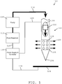
- FIG. 1 illustrates a diagram of one exemplary fluid ablation system 100.
- the system includes an elongate body 102 configured for insertion into a target volume of tissue.
- the elongate body can have a variety of shapes and sizes according to the geometry of the target tissue. Further, the particular size of the elongate body can depend on a variety of factors including the type and location of tissue to be treated, the size of the tissue volume to be treated, etc.
- the elongate body can be a thin-walled stainless steel needle between about 16- and about 18-gauge ( i .
- the elongate body 102 can include a pointed distal tip 104 configured to puncture tissue to facilitate introduction of the device into a target volume of tissue, however, in other embodiments the tip can be blunt and can have various other configurations.
- the elongate body 102 can be formed from a conductive material such that the elongate body can conduct electrical energy along its length to one or more ablation elements located along a distal portion of the elongate body.
- Emitter electrode 105 is an example of an ablation element capable of delivering RF energy from the elongate body.
- the emitter electrode 105 can be a portion of the elongate body 102.
- the elongate body 102 can be coated in an insulating material along its entire length except for the portion representing the emitter electrode 105. More particularly, in one embodiment, the elongate body 102 can be coated in 0.0381 mm (1.5 mil) of the fluoropolymer XylanTM 8840.
- the electrode 105 can have a variety of lengths and shape configurations. In one embodiment, the electrode 105 can be a 4 mm section of a tubular elongate body that is exposed to surrounding tissue.
- the electrode 105 can be located anywhere along the length of the elongate body 105 (and there can also be more than one electrode disposed along the length of the elongate body). In one embodiment, the electrode can be located adjacent to the distal tip 104. In other embodiments, the elongate body can be formed from an insulating material, and the electrode can be disposed around the elongate body or between portions of the elongate body.
- the electrode can be formed from a variety of other materials suitable for conducting current. Any metal or metal salt may be used. Aside from stainless steel, exemplary metals include platinum, gold, or silver, and exemplary metal salts include silver/silver chloride. In one embodiment, the electrode can be formed from silver/silver chloride. It is known that metal electrodes assume a voltage potential different from that of surrounding tissue and/or liquid. Passing a current through this voltage difference can result in energy dissipation at the electrode/tissue interface, which can exacerbate excessive heating of the tissue near the electrodes.
- a metal salt such as silver/silver chloride is that it has a high exchange current density.
- an electrode formed from a metal salt such as silver/silver chloride can reduce excessive energy generation at the tissue interface and thereby produce a more desirable therapeutic temperature profile, even where there is no liquid flow about the electrode.
- the electrode 105 or other ablation element can include one or more outlet ports 108 that are configured to deliver fluid from an inner lumen 106 extending through the elongate body 102 into surrounding tissue (as shown by arrows 109).
- the electrode 105 can be positioned near one or more outlet ports 108 formed in the elongate body 102.
- it can be desirable to position the electrode adjacent to the one or more outlet ports 108 to maximize the effect of the flowing fluid on the therapy.
- the outlet ports 108 can be formed in a variety of sizes, numbers, and pattern configurations.
- the outlet ports 108 can be configured to direct fluid in a variety of directions with respect to the elongate body 102.
- the elongate body 102 can be formed with an open distal end that serves as an outlet port.
- outlet ports 108 having a diameter of about 0.4 mm can be created around the circumference of the electrode 105 using Electrical Discharge Machining (EDM),
- EDM Electrical Discharge Machining
- the outlet ports can be disposed along a portion of the elongate body adjacent to the electrode, rather than being disposed in the electrode itself.
- the inner lumen 106 that communicates with the outlet ports 108 can also house a heating assembly 110 configured to heat fluid as it passes through the inner lumen 106 just prior to being introduced into tissue.
- the portion of the elongate body located distal to the electrode 105 or other ablation clement can be solid or filled such that the inner lumen 106 terminates at the distal end of the electrode 105.
- the inner volume of the portion of the elongate body distal to the electrode can be filled with a plastic plug that can be epoxied in place or held by an interference fit.
- the portion of the elongate body distal to the electrode can be formed from solid metal and attached to the proximal portion of the elongate body by welding, swaging, or any other technique known in the art.
- Fluid can be supplied to the inner lumen 106 and heating assembly 110 from a fluid reservoir 112.
- the fluid reservoir 112 can be connected to the inner lumen 106 via a fluid conduit 114.
- the fluid conduit 114 can be, for example, a length of flexible plastic tubing.
- the fluid conduit 114 can also be a rigid tube, or a combination of rigid and flexible tubing.
- Fluid can be urged from the fluid reservoir 112 into the inner lumen 106 by a pump 116.
- the pump 116 can be a syringe-type pump that produces a fixed volume flow with advancement of a plunger (not shown).
- An example of such a pump is a Model 74900 sold by Cole-Palmer Corporation of Chicago, IL.
- Other types of pumps, such as a diaphragm pump, may also be employed.
- the pump 116 can be controlled by a power supply and controller 118.
- the power supply and controller 118 can deliver electrical control signals to the pump 116 to cause the pump to produce a desired flow rate of fluid.
- the power supply and controller 118 can be connected to the pump 116 via an electrical connection 120.
- the power supply and controller 118 can also be electrically connected to the elongate body 102 via connection 122, and to a collector electrode 124 via connection 126.
- the power supply and controller 118 can be connected to the heating assembly 110 through a similar electrical connection.
- the collector electrode 124 can have a variety of forms.
- the collector electrode 124 can be a large electrode located outside a patient's body.
- the collector electrode 124 can be a return electrode located elsewhere along the elongate body 102, or it can be located on a second elongate body introduced into a patient's body near the treatment site.
- the power supply and controller 118 can drive the delivery of fluid into target tissue at a desired flow rate, the heating of the fluid to a desired therapeutic temperature, and the delivery of therapeutic ablative energy via the one or more ablation elements, such as electrode 105.
- the power supply and controller 118 can itself comprise a number of components for generating, regulating, and delivering required electrical control and therapeutic energy signals.
- the power supply and controller 118 can include one or more frequency generators to create one or more RF signals of a given amplitude and frequency. These signals can be amplified by one or more RF power amplifiers into relatively high-voltage, high-amperage signals, e.g., 50 volts at 1 amp.
- RF signals can be delivered to the ablation element via one or more electrical connections 122 and the elongate body 102 such that RF energy is passed between the emitter electrode 105 and the collector electrode 124 that can be located remotely on a patient's body.
- the one or more electrical connections 122 can extend through the inner lumen of the elongate body or along its outer surface to deliver current to the emitter electrode 105.
- the passage of RF energy between the ablation element and the collector electrode 124 can heat the tissue surrounding the elongate body 102 due to the inherent electrical resistivity of the tissue.
- the power supply and controller 118 can also include a directional coupler to feed a portion of the one or more RF signals to, for example, a power monitor to permit adjustment of the RF signal power to a desired treatment level.
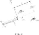
- FIG. 2 illustrates one embodiment of a medical device 200 having an elongate body 202 disposed on a distal end thereof configured for laparoscopic or direct insertion into a target area of tissue.
- the device 200 can include a handle 204 to allow an operator to manipulate the device.
- the handle 204 can include one or more electrical connections 206 that connect various components of the elongate body ( e.g., the heating assembly and ablation element 205) to, for example, the power supply and controller 118 described above.
- the handle 204 can also include at least one fluid conduit 208 for connecting a fluid source to the device 200.
- device 200 is one exemplary embodiment of a medical device that can be adapted for use in fluid enhanced ablation
- a number of other devices can also be employed.
- a very small elongate body can be required in treating cardiac dysrhythmias, such as ventricular tachycardia.
- an appropriately sized elongate body can be, for example, disposed at a distal end of a catheter configured for insertion into the heart via the circulatory system.
- a stainless steel needle body between about 20- and about 25-gauge ( i . e ., an outer diameter of about 0.5 millimeters to about 0.9 millimeters) can be disposed at a distal end of a catheter.
- the catheter can have a variety of sizes but, in some embodiments, it can have a length of about 120 cm and a diameter of about 8 French ("French” is a unit of measure used in the catheter industry to describe the size of a catheter and is equal to three times the diameter of the catheter in millimeters).
- Ablation generally involves the application of high or low temperatures to cause the selective necrosis and/or removal of tissue.
- a threshold temperature for causing irreversible thermal damage to tissue is generally accepted to be about 41° Celsius (C). It is also known that the time required to achieve a particular level of cell necrosis decreases as the treatment temperature increases further above 41° C. It is understood that the exact time/temperature relationship varies by cell type, but that there is a general relationship across many cell types that can be used to determine a desired thermal dose level.
- therapeutic temperature may refer to any temperature in excess of 41° C, but the delivered dose and, ultimately, the therapeutic effect are determined by the temporal history of temperature (i.e., the amount of heating the tissue has previously endured), the type of tissue being heated, and equation (1).
- the therapeutic temperature should be uniform throughout the tissue being treated so that the thermal dose is uniformly delivered.
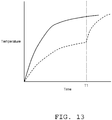
- FIG. 3 illustrates the performance profiles of several ablation techniques by showing a simulated temperature achieved at a given distance from an ablation element, such as electrode 105.
- the first profile 302 illustrates the performance of RF ablation without the use of fluid enhancement.
- the temperature of the tissue falls very sharply with distance from the electrode. This means that within 10 millimeters of the ablation element the temperature of the tissue is still approximately body temperature (37° C), far below the therapeutic temperature of 50° C discussed above.
- body temperature 37° C
- the temperature is very high, meaning that the tissue will more quickly desiccate, or dry up, and char. Once this happens, the impedance of the tissue rises dramatically, making it difficult to pass energy to tissue farther away from the ablation element.
- a second tissue temperature profile 304 is associated with a second prior art system similar to that described in U.S. Patent No. 5,431,649 .
- an electrode is inserted into tissue and imparts a 400 kHz RF current flow of about 525 mA to heat the tissue.
- Body temperature (37° C) saline solution is simultaneously injected into the tissue at a rate of 10 ml/min.
- the resulting tissue temperature profile 304 is more uniform than profile 302, but the maximum temperature achieved anywhere is approximately 50° C.
- the temperature profile 304 exceeds the generally accepted tissue damaging temperature threshold specified for one minute of therapy in only a small portion of the tissue. As described above, such a small temperature increment requires significant treatment time to achieve any therapeutically meaningful results.
- a third tissue temperature profile 306 is achieved using the teachings of the present disclosure.
- an electrode formed from silver/silver chloride is inserted into tissue and imparts a 480 kHz RF current flow of 525 mA to heat the tissue.
- Saline solution heated to 50° C is simultaneously injected into the tissue at a rate of 10 ml/min.
- the resulting temperature profile 306 is both uniform and significantly above the 50° C therapeutic threshold out to 15 millimeters from the electrode. Moreover, because the temperature is uniform within this volume, the thermal dose delivered is also uniform through this volume.
- the uniform temperature profile seen in FIG. 3 can be achieved by the introduction of heated fluid into the target tissue during application of ablative energy.
- the fluid convects the heat deeper into the tissue, thereby reducing the charring and impedance change in tissue that occurs near the ablation element, as shown in profile 302.
- the fluid is heated to a therapeutic level, it does not act as a heat sink that draws down the temperature of the surrounding tissue, as seen in profile 304. Therefore, the concurrent application of RF energy and perfusion of heated saline solution into the tissue eliminates the desiccation and/or vaporization of tissue adjacent to the electrode, maintains the effective tissue impedance, and increases the thermal transport within the tissue being heated with RF energy.
- the total volume of tissue that can be heated to therapeutic temperatures is thereby increased.
- experimental testing has demonstrated that a volume of tissue having a diameter of approximately 8 centimeters ( i . e ., a spherical volume of approximately 156 cm 3 ) can be treated in 5 minutes using the fluid enhanced ablation techniques described herein.
- conventional RF can only treat volumes having a diameter of approximately 3 centimeters ( i.e., a spherical volume of approximately 14 cm 3 ) in the same 5-minute time span.
- fluid enhanced ablation devices have a greater number of parameters that can be varied to adjust the shape of the treatment profile according to the tissue being treated.
- an operator or control system can modify parameters such as saline temperature (e.g., from about 40° C to about 80° C), saline flow rate ( e.g., from about 0 ml/min to about 20 ml/min), RF signal power (e.g., from about 0 W to about 100 W), and duration of treatment ( e.g., from about 0 minutes to about 10 minutes) to adjust the temperature profile 306.
- saline temperature e.g., from about 40° C to about 80° C
- saline flow rate e.g., from about 0 ml/min to about 20 ml/min
- RF signal power e.g., from about 0 W to about 100 W
- duration of treatment e.g., from about 0 minutes to about 10 minutes
- different electrode configurations can also be used to vary the treatment.
- the emitter electrode 105 illustrated in FIG. 1 is configured as a continuous cylindrical band adapted for a mono-polar current flow
- the electrode can also be formed in other geometries, such as spherical or helical, that form a continuous surface area, or the electrode may have a plurality of discrete portions.
- the electrodes may also be configured for bipolar operation, in which one electrode (or a portion of an electrode) acts as a cathode and another electrode (or portion thereof) acts as an anode.
- a preferred fluid for use in the SERF ablation technique is sterile normal saline solution (defined as a salt-containing solution). However, other liquids may be used, including Ringer's solution, or concentrated saline solution.
- a fluid can be selected to provide the desired therapeutic and physical properties when applied to the target tissue and a sterile fluid is recommended to guard against infection of the tissue.
- ablative energy In fluid enhanced ablation therapy, ablative energy generally expands from an ablation element, such as emitter electrode 105, in a roughly spherical pattern. This, in turn, creates ablation therapy treatment zones, volumes, or regions ( i.e., regions that receive a therapeutic dose of ablative energy by reaching a therapeutic temperature for a period of time, as discussed above) that have a roughly spherical shape.
- the diameter of the spherical treatment zone can increase as the treatment time is lengthened.
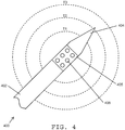
- FIG. 4 shows one embodiment of an ablation device 400 that includes an elongate body 402 having a distal tip 404 and an emitter electrode 405.
- a plurality of outlet ports 408 can be positioned along an outer surface of the emitter electrode 405 and can be configured to deliver fluid into the tissue surrounding the elongate body 402.
- a treatment zone develops at a first time that is defined by the dotted lines labeled T 1 . While drawn as a two-dimensional circle, one skilled in the art will appreciate that the treatment zone represented is roughly spherical in shape.
- the treatment time increases, so too does the diameter of the treatment zone, until it reaches the dotted lines labeled T 2 at a second time that is greater than the first time. Similarly, at a third time greater than the second time, the treatment zone can reach the dotted lines labeled T 3 .
- the propagation of the treatment zone over time can be affected by a variety of factors. These can include factors related to the tissue being treated (e.g., features, tissue type, amount of heating already endured, etc.) as well as factors related to the therapy operating parameters (e.g. temperature of fluid being delivered, flow rate of fluid being delivered, level of ablative energy being delivered, etc.). As mentioned above, fluid enhanced ablation has a greater number of tunable operating parameters than conventional ablation therapy techniques, and all of these can affect the development of the treatment zone.
- FIG. 5 illustrates a few examples of treatment profiles that can be achieved by adjusting various operating parameters of the fluid enhanced ablation system.
- initial operating parameters may produce an initial treatment profile 502.
- the treatment profile 502 does not bring tissue located a distance away from the ablation element above the therapeutic temperature.
- an operator or control system can, for example, increase the ablative energy level being applied to the tissue. This can result in the second treatment profile 504.
- the second treatment profile 504 delivers therapeutic heat farther into tissue, but also delivers significantly more heat into tissue located closer to the ablation element. This additional heat may be undesirable and can lead to charring of the tissue.
- the operator or control system can further adjust the operating parameters of the system by, for example, increasing the flow rate of therapeutically heated saline being introduced into the tissue at or immediately adjacent to the ablative element. Doing so can have the effect of smoothing out the temperature spike seen in the treatment profile 504, producing the treatment profile 506.
- This treatment profile brings tissue to a therapeutic temperature over the largest distance from the ablation element and avoids an undesirable temperature spike closer to the ablation element.
- an elongate body for use in fluid enhanced ablation having a single temperature sensor located immediately adjacent to the ablation element (i.e., the emitter electrode). This sensor location, however, does not report the temperature of tissue at locations a distance apart, i . e ., remote, from the ablation element.
- fluid enhanced ablation systems can include one or more temperature sensors that are introduced at various locations a distance apart from the ablation element to provide a more accurate assessment of the propagation of the thermal energy being delivered into tissue, thereby allowing a more accurate calculation of the therapeutic dosage and more control over the ablation therapy generally.
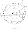
- the device 600 includes an elongate body 602 having an inner lumen (not shown) extending therethrough.
- the elongate body 602 can have a pointed distal tip 604 to facilitate entry into tissue, though other shapes can be used, as described above.
- the elongate body 602 also includes an ablation element 605 having one or more outlet ports 608 formed therein that are in fluid communication with the inner lumen extending through the elongate body 602.
- the elongate body 602 can be inserted into a lesion 610 or other targeted volume of tissue and positioned such that the ablation element 605 is located substantially in the center of the lesion 610.
- Ablative energy and heated fluid can then be delivered simultaneously into the surrounding tissue to begin therapy (in some embodiments, however, the delivery of heated fluid alone can produce the desired therapeutic result).
- the dotted lines T 1 , T 2 , T 3 indicate the portion of the lesion that receives a therapeutic dose of ablative energy at times T 1 , T 2 , T 3 , where T 3 is greater than T 2 , and T 2 is greater than T 1 .
- the elongate body 602 also includes two temperature sensors located along the length of the elongate body to measure the temperature of adjacent tissue.
- a first temperature sensor 612 can be located immediately adjacent to the ablation element 605 in either a proximal or distal direction.
- the second temperature sensor 614 can be located a distance apart from the ablation element 605 along the length of the elongate body 602.
- the second temperature sensor 614 can thus be configured to measure the temperature of adjacent tissue that is located a distance away from the ablation element 605 and from the tissue immediately adjacent to the ablation element.
- the location of the second temperature sensor 614 can be selected such that the second temperature sensor is positioned at the edge of the desired treatment zone (e.g., lesion 610).
- the second temperature sensor 614 can be positioned at a location between the ablation element and the edge of the desired treatment zone. In certain embodiments, the second temperature sensor 614 can be positioned at least about 5 mm from the ablation element 605 so that the temperature measurement from the second temperature sensor remains distinct from the measurement of the first temperature sensor 612.
- the second temperature sensor 614 can be positioned at a location proximal or distal to the ablation element. In some embodiments, however, it can be preferable to position the second temperature sensor 614 proximal to the ablation element 605, as doing so requires a shallower insertion of the elongate body 602 into tissue. For example, if the second temperature sensor 614 is located distal to the ablation element 605, the elongate body 602 must be inserted into, for example, the lesion 610 to a depth greater than the configuration shown in FIG. 6 so that the ablation element 605 is positioned at the center of the lesion 610 and the second temperature sensor 614 is positioned near the periphery of the lesion opposite from its illustrated position in the figure.
- the second temperature sensor 614 can be positioned such that it is located near the periphery of the targeted treatment volume, as shown in FIG. 6 .
- This configuration can be advantageous because the second temperature sensor 614 can be used to provide an indication that therapy can be terminated. That is, once a temperature sensor located at the periphery of a targeted treatment volume indicates that a therapeutic dose of energy has been delivered at the periphery (e.g., a threshold temperature is reached for a given amount of time), an operator or control system can terminate the ablation therapy.
- the temperature measured by the second temperature sensor 614 can be compared to the temperature measured by the first temperature sensor 612 to determine if the treatment volume has received a therapeutic dose of ablative energy.
- the second temperature sensor 614 can be accomplished in a variety of manners.
- the targeted treatment volume can be imaged in advance of ablation therapy using any number of medical imaging technologies such as ultrasound, Magnetic Resonance Imaging (MRI), etc.
- MRI Magnetic Resonance Imaging
- an operator can select an appropriately sized elongate body having a distance between the first and second temperature sensors 612, 614 that is approximately equal to half the diameter of the targeted volume or lesion 610.
- the second temperature sensor 614 can be configured to slide or otherwise adjust along the length of the elongate body 602. In such an embodiment, the position of the second temperature sensor 614 can be adjusted following a determination, via medical imaging or other measurement technology, of the size of the targeted treatment volume.
- a plurality of additional temperature sensors can be placed along the length of the elongate body to provide more detailed and precise feedback regarding the heating of tissue surrounding the elongate body. This can be accomplished, for example, by placing a plurality of temperature sensors in a line extending proximally from the first temperature sensor 612 to the second temperature sensor 614.
- the additional temperature sensors can provide additional observation points that allow more precise tracking of the propagation of thermal energy from the ablation element 605.
- FIG. 7 illustrates one embodiment of a fluid enhanced ablation device having remotely located temperature sensors positioned both proximally and distally from an ablation element. Similar to the devices described above, the device 700 can include an elongate body 702 having a proximal end and a distal tip 704, as well as an ablation element 705 (e.g., an emitter electrode) with one or more outlet ports 708 formed therein to allow fluid to pass from an inner lumen of the elongate body 702 into surrounding tissue.
- an ablation element 705 e.g., an emitter electrode
- the elongate body can include a plurality of temperature sensors including first, second, and third proximal temperature sensors 710, 711, 712 positioned proximal of the ablation element 705.
- the first temperature sensor 710 can be located a first distance away from the ablation element 705.
- the second temperature sensor 711 can be located a second distance away from the ablation element 705 that is greater than the first distance.
- the third temperature sensor 712 can be located a third distance away from the ablation element 705 that is greater than the second distance.
- the elongate body can also include first, second, and third distal temperature sensors 713, 714, 715 positioned distal of the ablation element 705 in a similar spacing arrangement as temperature sensors 710, 711, 712.
- first, second, and third distal temperature sensors 713, 714, 715 positioned distal of the ablation element 705 in a similar spacing arrangement as temperature sensors 710, 711, 712.
- the end result is a fluid enhanced ablation device capable of measuring temperature along a longitudinal axis of the elongate body at a variety of locations on either side of an ablation element to accurately map the temperature of tissue surrounding the elongate body.
- the plurality of temperature sensors can be positioned in a single line, e.g., extending along a longitudinal axis of the elongate body. In other embodiments, however, the temperature sensors can be positioned at various locations around the circumference of the elongate body, thereby forming a corkscrew or spiral pattern.
- the elongate body can include additional lines of temperature sensors similar to the sensors shown in FIG. 7 , each of which can be positioned at a different location around the circumference of the elongate body. These additional temperature sensors can provide still greater detail of the temperature in the tissue surrounding the elongate body 702.
- the device illustrated in FIG. 7 can be positioned in a treatment volume (e.g., lesion 709) such that the ablation element 705 is located approximately in the center of the volume.
- the first, second, and third proximal temperature sensors 710, 711, 712 can be positioned symmetrically with respect to the first, second, and third distal temperature sensors 713, 714, 715.
- the size of the elongate body 702 and the spacing of the temperature sensors along the elongate body can be selected according to the size of the lesion 709, which can be imaged before ablation therapy using any of the medical imaging technologies discussed above or otherwise known in the art.
- therapy can begin by delivering therapeutically heated saline alone or in combination with ablative energy from the ablation element 705.
- a control system or operator can monitor the readouts from the plurality of temperature sensors to determine the extent of the therapeutic treatment volume. For example, at a first time T 1 the operator or control system can detect a therapeutic temperature from the first proximal and distal temperature sensors 710, 713, but not from any of the other temperature sensors. This can indicate that the volume shown by the dotted lines T 1 has received a therapeutic dose of ablative energy.
- the second proximal and distal temperature sensors 711, 714 can detect a therapeutic temperature as the treatment region expands to the dotted lines T 2 .
- the third proximal and distal temperature sensors 712, 715 can detect a therapeutic temperature, thereby indicating that the region represented by the dotted lines T 3 has received a therapeutic dose of ablative energy.
- the location of the third proximal and distal temperature sensors 712, 715 can be selected such that the sensors are located on the periphery of a desired treatment volume, such as the lesion 709 shown in the figure.
- any of the illustrated proximal temperature sensors 710, 711, 712 or the distal sensors 713, 714, 715 can detect a temperature in any order and at any time. Any particular sensor can detect a temperature at a same time or a different time than any other temperature sensor at any time throughout the therapy.
- the device 700 can be configured such that the most proximal and most distal temperature sensors (e.g., sensors 712, 715) are positioned outside of the desired treatment volume (e.g., lesion 709) while an inner set of temperature sensors (e.g., sensors 711, 714) are positioned at the edge of the treatment volume and one or more additional temperature sensors (e.g., sensors 710, 713) are within the treatment volume.
- the temperature sensors located at the edge of the treatment volume can indicate when therapy is complete, while the inner temperature sensors can monitor the uniformity of temperature within the treatment volume and the temperature sensors positioned outside of the treatment volume can ensure that adjacent tissue does not receive a therapeutic dose of heat.
- the devices described above can be formed in a variety of sizes suitable to provide therapy to a wide range of lesions.
- lesions ranging from 5 mm to 100 mm have been treated using the devices disclosed herein.
- the spacing between any temperature sensors included in a device can depend on the size of the device and the size of the lesion or other target volume of tissue being treated.
- a device configured for use in tumors or other large lesions e.g., greater than 3 cm in diameter
- smaller devices such as a catheter-based device configured for use in treating ventricular tachycardia, can have temperature sensors positioned at intervals of about 2 mm to about 3 mm both proximally and distally from an ablation element.
- FIG. 8 illustrates an exploded view showing one embodiment of the construction of a fluid enhanced ablation device 800.
- An elongate body 802 is shown having an inner lumen 806 that houses components configured to deliver therapeutically heated fluid to the surrounding tissue.
- the inner lumen 806 can include a dual-wire heating assembly 810 that is configured to heat fluid flowing through the inner lumen 806 by passing electrical energy between the two wires and through the fluid.
- the dual-wire heating assembly 810 can include one or more spacers 811 configured to hold the two wires of the heating assembly 810 in a substantially fixed geometric relationship with respect to each other and/or the elongate body 802.
- the elongate body 802 can include a temperature sensor 812 embedded in a sidewall of the elongate body.
- the temperature sensor 812 shown is a fine-wire thermocouple known in the art that utilizes different conducting materials to produce a voltage proportional to a temperature difference between the ends of the materials.
- the thermocouple can include a chromel (Nickel-Chromium alloy) wire 813 and a constantan (Copper-Nickel alloy) wire 814 connected at the location of the thermocouple 812.
- thermocouple or other temperature sensor can be positioned along the elongate body 802 in a variety of manners.
- the sensor can be placed on an outer surface of the elongate body and any connecting wires can be run through the elongate body and up the inner lumen 806, or the wire can be run along an outer surface of the elongate body 802.
- the elongate body 802 can include outer facing grooves, inner facing grooves, or passages formed through a sidewall thereof (depending on the thickness of the sidewall) adapted to accommodate wires connecting to one or more temperature sensors.
- wireless temperature sensors can be positioned along the elongate body 802 to remove the need to run connecting wires to a proximal end of the elongate body.
- thermocouple temperature sensor 812 is shown embedded in the sidewall of the elongate body 802.
- the temperature sensor 812 can be embedded by forming a hole in a sidewall of the elongate body 802, placing the thermocouple junction in the hole, and sealing the wires in place with a conductive epoxy.
- a 0.8 mm diameter hole can be formed in a 25 cm long 16-gauge thin-walled stainless steel elongate body, and a thermocouple formed from 0.08 mm diameter Type E (chromel constantan) wires can be placed in the hole and sealed with epoxy.
- thermocouple sensor can be affixed to the inside of a thermally conductive elongate body to detect the temperature in the surrounding tissue through the elongate body. In such embodiments, calibration may be necessary to compensate for the indirect measurement.
- one or more temperature sensors can be configured to be adjustable along the length of the elongate body. This can be accomplished, for example, by placing one or more temperature sensors in grooves or tracks running along the length of the elongate body. Alternatively, one or more temperature sensors can be placed on one or more bands disposed around the elongate body that can be slidably moved up and down the length of the elongate body. In still other embodiments, the elongate body can be formed with a plurality of recesses configured to removably receive a temperature sensor module.
- the recesses can be formed at a variety of spaced apart positions such that a user can select the most appropriate recess for temperature sensor placement prior to ablation therapy.
- the remaining recesses can be left empty or filled with a plug to maintain the smooth profile of the elongate body.
- connecting wires from any temperature sensors can be run along an outer surface of the elongate body or can extend into the inner lumen at a particular location along the elongate body.
- wireless temperature sensors can be employed to remove the need for connecting wires.
- the inner lumen 806 of the elongate body 802 can also include an insulating tube 816 that houses the dual-wire heating assembly 810 and that contains any fluid flowing through the inner lumen 806.
- the insulating tube 816 can prevent the temperature of the flowing fluid from affecting the temperature measured by the thermocouple 812.
- the insulating tube 816 can be formed from any number of thermally insulating materials and, in one embodiment, can be formed from a polymer such as polyimide.
- the insulating tube 816 can be constructed so as to utilize the relatively efficient thermal insulating properties of air.
- FIG. 9A illustrates one embodiment of an insulating tube 916 having a central lumen 906 and a plurality of secondary lumens 918 formed in a sidewall thereof.
- Such an insulating tube 916 can be formed, for example, by extrusion methods known in the art.
- the wires associated with one or more of the thermocouples can be run outside the tube 916 or through one of the secondary lumens 918.
- an insulating tube 920 can be formed with one or more features configured to create an air gap between the tube and the sidewalls of the elongate body 802.
- the insulating tube 920 can include, for example, a plurality of tabs 922 running longitudinally along the tube and extending laterally therefrom. When placed within the inner lumen 806 of the elongate body 802, the tabs 922 can prevent the insulating tube 920 from directly contacting the sidewalls of the elongate body.
- an air gap 924 can be created between the thermocouple 812 or other temperature sensor and the insulating tube 920 containing heated fluid for use in fluid enhanced ablation.
- the degree of thermal isolation of the flowing saline from the one or more temperature sensors can vary according to the particular design of a given device. In some embodiments, it can be desirable to achieve a particular degree of thermal isolation. This can be quantified, for example, as a difference between a first temperature recorded with no fluid flow through the inner lumen and a second temperature recorded with room temperature saline flowing through the inner lumen. In some embodiments, devices can be configured to limit this difference to 2° C or less.
- the flowing fluid utilized during ablation therapy is not the only thermal interference that can affect the one or more temperature sensors.
- the elongate body itself can, in some embodiments, affect the temperature measured by the thermocouple 812 or other temperature sensor.
- the elongate body 802 is formed from a conducting material
- the elongate body itself is likely to conduct heat along a thermal gradient, thereby "flattening" the gradient that might otherwise be observed in the tissue. This can result in the elongate body being relatively cold while the surrounding tissue is hot at some locations, and vice versa at other locations. This can, in turn, result in the measurement of an incorrect temperature or temperature gradient by the one or more temperature sensors positioned along the length of the elongate body.
- the influence of the elongate body on temperatures measured by the one or more temperature sensors disposed thereon can be managed using a variety of techniques.
- the material, cross-sectional size, and sidewall thickness of the elongate body can be selected so as to match the thermal conductivity of the surrounding tissue. This, however, can be a costly, difficult, and time-consuming calibration to make.
- a variety of methods can be employed to compensate for any thermal interference from the elongate body. These include mathematical analysis to correct for the influence, empirical observation to calibrate the sensors, or controlled experiments to characterize the effect of the elongate body on the temperature measurements.
- the elongate body and one or more temperature sensors can be calibrated such that the temperature at a position located a distance apart from an ablation element is within 5° C of the true temperature within the surrounding tissue at the same position.
- the elongate body may not introduce the thermal interference discussed above.
- the temperature of the elongate body may not affect the readings of any temperature sensors positioned along the elongate body.
- the embodiments described above utilize one or more temperature sensors disposed along the elongate body at locations remote from an ablation element to measure the temperature of tissue surrounding the elongate body.
- the one or more temperature sensors generally provide readings along a longitudinal axis of the elongate body.
- one or more temperature sensors can be located remotely from both the ablation element and the elongate body itself. Positioning one or more temperature sensors at various locations within the volume of tissue surrounding the elongate body and ablation element can provide data regarding the three-dimensional propagation of thermal energy within the surrounding tissue.
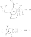
- FIG. 10 illustrates one embodiment of a fluid enhanced ablation device including an elongate body 1102 having a distal tip 1104, an ablation element 1105, and one or more outlet ports 1108 formed in the elongate body to deliver fluid from an inner lumen 1106 to tissue surrounding the elongate body.
- the device also includes a plurality of temperature sensors 1112 each located at a distal end of an elastic tine 1114 that is configured to extend from the elongate body 1102 into surrounding tissue.
- the elastic tines can be formed from a variety of materials and, in one embodiment, are formed from Nitinol (Nickel-Titanium alloy).
- the temperature sensors disposed at the distal ends of the elastic tines can be any of the temperature sensors discussed above, for example, fine-wire thermocouples or wireless sensors. If a wired temperature sensor is used, the tines can be formed with an inner lumen that accommodates the wired connection, or the wires can be run along an outer surface of the tine and affixed thereto using, for example, a thin polymer coating.
- the tines 1114 can be initially retracted into the elongate body 1102, with the sensors 1112 disposed within the elongate body 1102, such that they do not interfere with insertion of the elongate body into the desired treatment volume of tissue.
- the tines 1114 can be housed within passages formed in the sidewall of the elongate body (shown as dotted lines in FIG. 10 ), or can be housed within the inner lumen 1106 of the elongate body.
- the tines 114 can be extended from outlet ports formed in the elongate body 1102 and can assume, for example, the configuration shown in FIG. 10 .
- the temperature sensors 1112 located at the distal end of each tine 1114 can detect the temperature of tissue and determine when a therapeutic dose of ablative energy has been delivered to the entire treatment volume.
- the tines can be retracted into the elongate member 1102 prior to removing or repositioning the elongate member 1102.
- tines 1114 can be utilized, and the tines can be preconfigured to assume a particular shape within the surrounding tissue using the shape memory characteristics of particular materials such as Nitinol.
- a series of tines 1114 can be used to form, for example, a spherical detection pattern surrounding the elongate body 1102.
- a spherical pattern of temperature sensors can allow a control system or operator to more precisely and accurately determine when a desired treatment volume has received a therapeutic dose of ablative energy.
- the physical separation from the elongate body provided by the elastic tines 1114 can also substantially eliminate the thermal influence of the elongate body and/or flowing fluid discussed above. Accordingly, in some embodiments, shorter elastic tines can be employed to provide thermal isolation while maintaining the proximity of the temperature sensors to the elongate body.
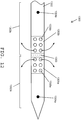
- An exemplary embodiment is illustrated in FIG. 11 , which shows the use of temperature sensors 1212 in combination with very short elastic tines 1214.
- the elastic tines shown in FIGS. 10 and 11 can be combined with any of the previously discussed embodiments to create devices having a plurality of temperature sensors positioned both along an axis of the elongate body and in the tissue surrounding the elongate body.
- each tine can vary in length such that a device can have one or more longer tines and one or more shorter tines. Such a configuration can allow a device to obtain temperatures at a variety of distances from an ablation element or therapeutically heated saline source.
- Any device incorporating retractable tines with temperature sensors disposed thereon can also include an actuator configured to deploy the tines from the elongate body 1102.
- Exemplary actuator mechanisms can include a sliding lever, a trigger, etc.
- Each tine can have its own actuator mechanism or a single mechanism can be used to control and deploy a plurality of tines.
- FIG. 12 illustrates another embodiment of an ablation device 1300 having one or more temperature sensors located a distance apart from an ablation element.
- the device in FIG. 12 is divided into portions by one or more baffling members.
- the device is divided into a first distal section 1302a and a second proximal section 1302b by a baffling element 1303.
- the baffling element 1303 can be an inner wall that separates the inner lumen of the first section 1302a of the elongate body from the inner lumen of the second section 1302b of the elongate body.
- Each section 1302a, 1302b can include an ablation element, such as an emitter electrode 1305a, 1305b, as well as one or more outlet ports 1308a, 1308b formed along the elongate body 1302 and/or emitter electrode 1305a, 1305b that are in fluid communication with the inner lumen of each section.
- the sections 1302a, 1302b can further include one or more temperature sensors 1304a, 1304b disposed along the elongate body and configured to detect the temperature of tissue surrounding the elongate body 1302.
- the temperature sensors can be implemented according to any of the teachings of the present disclosure and, in some embodiments, the sensors can be fine-wire chromel-constantan thermocouples embedded in a hole formed in the sidewall of the elongate body 1302.
- the temperature sensors 1304a, 1304b can be positioned at any location along the elongate body 1302 but, in some embodiments, can be positioned symmetrically with respect to, i.e., at an equal distance away from, the ablation elements 1305a, 1305b. This arrangement can allow for a more accurate measurement of the uniformity of expansion of the treatment zone.
- FIG. 13 shows simulated temperature measurements for the two temperature sensors 1304a, 1304b over time.
- the solid line represents the temperatures recorded by temperature sensor 1304a during fluid enhanced ablation therapy
- the dashed line represents the temperatures recorded by temperature sensor 1304b.
- the initial conditions at the beginning of therapy are identical, i.e., the same amount of ablative energy is being delivered from both ablation elements 1305a, 1305b, and the fluid is being delivered from both sections 1302a, 1302b at the same temperature and flow rate.
- tissue surrounding temperature sensor 1304b is not heating to the same therapeutic level as the tissue surrounding temperature sensor 1304a. Accordingly, at time T 1 shown in the figure, the operating parameters of the ablation therapy are altered.
- any or all of the following steps can be taken: (1) the level of ablative energy can be increased in ablation element 1305b, (2) the flow rate of fluid from section 1302b can be increased, (3) the temperature of the fluid from section 1302b can be increased, (4) the level of ablative energy can be decreased in ablation element 1305a, (5) the flow rate of fluid from section 1302a can be decreased or (6) the temperature of fluid from second 1302a can be decreased or the flow rate can be increased and the temperature decreased (to essentially urge the heated fluid from section 1302b toward the temperature sensor 1304b).
- FIG. 14 illustrates a semi-transparent view of the device of FIG. 12 and shows one embodiment of the internal construction of the elongate body divided into a plurality of sections by one or more baffling members 1303.
- the inner lumen of section 1302a can be separated from section 1302b by the baffling member 1303.
- the baffling member 1303 can be constructed in a variety of manners.
- the baffling member can be an integrated portion of the elongate body 1302, or it can be a separate component secured in the inner lumen 1506 of the elongate body 1302 by an adhesive or other retaining component or material.
- the baffle 1303 can be formed, for example, from a plastic or other suitable material.
- the baffling element 1303 can further include one or more lumens formed therein that are each configured to receive a cannula, such as cannula 1510a.
- the cannula 1510a can be formed from metal, plastic, or plastic having a metal lining, and can include an inner lumen that provides a fluid passageway to the proximal end of the device 1300 through any intervening baffles ( e.g., the baffle 1303) and sections ( e.g., the second section 1302b).
- the inner lumen of the cannula 1510a is not in fluid communication with the inner lumen of any other section ( e.g., section 1302b).
- the inner lumen 1506 can also include additional cannulas configured to deliver fluid to other sections of the device 1300.
- the inner lumen 1506 can include a cannula 1510b configured to deliver fluid from a proximal end of the device 1300 into the second section 1302b of the device 1300.
- the inner lumen 1506 can include as many cannulas as there are sections in the device. Further, the device 1300 can have any number of sections depending on the desired shape of the treatment zone. For example, the device 1300 can include two sections as illustrated in FIG. 12 , or can have three or more sections.
- the cannulas can each be rigidly held in position by a spacer element (e.g., an element similar to the baffle 1303 but also including one or more lumens to allow the passage of fluid around the baffle) or can be allowed to float in the inner lumen 1506.
- the cannulas can include features formed on an external surface thereof to prevent contact with other cannulas or the inner walls of the inner lumen 1506. Exemplary features include fins or ribs formed on the outer surface of the cannulas.
- Each cannula 1510a, 1510b can be connected at a proximal end to an independent fluid source.
- Each cannula 1510a, 1510b can also include an independent heating assembly disposed within the inner lumen of the cannula near its distal end.
- An exemplary heating assembly can include, for example, a single wire 1514a, 1514b running through the inner lumen of the cannula 1510a, 1510b that is configured to pass RF energy through fluid within the inner lumen of the cannula into the inner wall of the cannula 1510a, 1510b.
- the wire 1514a, 1514b can include one or more spacers disposed thereon to prevent the wire from directly contacting the conductive portion of the cannula 1510a, 1510b.
- each cannula 1510a, 1510b be at least partially formed from an electrically conductive material (to receive RF energy from the wire 1514a, 1514b).
- the cannulas 1510a, 1510b can be coated in an insulating material so as to prevent any electrical shorts due to contact with each other or the inner walls of the inner lumen 1506 of the device 1300.
- a thermally insulating material can also be used to coat the cannulas 1510a, 1510b to prevent the temperature of fluid in any one section from influencing the temperature of fluid in other sections.
- the fluid flow rate can be high enough that fluid does not spend enough time in any one section to influence, or be influenced by, the temperature of fluid in that section.
- thermal insulation of the cannulas 1310a, 1310b is not necessary.
- the cannulas 1510a, 1510b can also include a temperature sensor configured to provide feedback regarding the temperature of fluid being delivered to a section of the device 1300.
- the cannula 1510a can include a dual-wire thermocouple 1512a configured to extend beyond the distal end of the cannula 1510a such that the thermocouple can measure the temperature of fluid within the first section 1302a after it exits the cannula and mixes within the inner lumen 1506 before exiting into the surrounding tissue through the outlet ports 1308a.
- the two thermocouple wires 1520, 1522 can extend through the inner lumen of the cannula 1510a back to the proximal end of the device 1510a.
- the wires can be connected to signal processing electronics as known in the art to determine the temperature of the fluid in the first section 1302a.
- the second cannula 1510b can also include a temperature sensor 1512b, such as a dual-wire thermocouple formed from two wires 1516, 1518.
- the sensor 1512b can similarly be configured to extend beyond the distal end of the cannula 1510b into the second section 1302b such that the temperature measured by the sensor 1512b represents the temperature of mixed fluid that is about to be delivered into surrounding tissue via outlet ports 1308b.
- a variety of temperature sensors can be employed in the devices of the present disclosure, including, for example, chromel-constantan fine-wire thermocouples.
- medical devices as disclosed herein can be configured for insertion into a target volume of tissue directly during an open surgical procedure.
- the medical devices can be configured to be passed through one or more layers of tissue during a laparoscopic or other minimally invasive procedure.
- the devices can be configured for introduction into a patient via an access port or other opening formed through one or more layers of tissue, or via a natural orifice ( i . e ., endoscopically).
- a portion of a surgical device e.g., a distal portion of the elongate body 102, can be inserted into a target treatment volume such that an ablation element is disposed within the treatment volume.
- the ablation element can be positioned near the center of the treatment volume. If there are any extendable members, such as elastic tines having temperature sensors on a distal end thereof, they can be deployed into the tissue surrounding the elongate member.
- ablative energy and fluid heated to a therapeutic temperature can be simultaneously delivered through the devices into the treatment volume. In some embodiments, however, therapeutically heated fluid alone can be used without ablative energy.
- One or more temperature sensors associated with the device can monitor the temperature of tissue at various locations within the target treatment volume. The detected temperatures can be displayed to an operator or monitored by a control program administering the ablation therapy. In some embodiments, the temperatures measured at locations a distance apart from an ablation element can be compared to temperatures measured at or immediately adjacent to the ablation element.
- Any anomalies detected during therapy can be addressed by the operator or control system. Addressing a detected heating anomaly can involve simply maintaining the therapy until all temperature readings report a uniformly delivered therapeutic dose, or it can require the alteration of other therapy operating parameters such as ablative energy level, fluid flow rate, fluid temperature, etc. These parameters can be adjusted individually or in combination by either an operator or control system, as described above.
- the delivery of ablative energy and fluid can be stopped. Any extending temperature sensors can be retracted into the ablation device, and the device can then be removed and/or repositioned if additional therapy is required.
- the devices disclosed herein can be designed to be disposed after a single use, or they can be designed for multiple uses. In either case, however, the device can be reconditioned for reuse after at least one use. Reconditioning can include any combination of the steps of disassembly of the device, followed by cleaning or replacement of particular pieces, and subsequent reassembly. In particular, the device can be disassembled, and any number of the particular pieces or parts of the device can be selectively replaced or removed in any combination. Upon cleaning and/or replacement of particular parts, the device can be reassembled for subsequent use either at a reconditioning facility or by a surgical team immediately prior to a surgical procedure.
- reconditioning of a device can utilize a variety of techniques for disassembly, cleaning/replacement, and reassembly. Use of such techniques, and the resulting reconditioned device, are all within the scope of the present disclosure.
- the surgical devices disclosed herein may be disassembled partially or completely.
- the elongate body 202 of the medical device 200 shown in FIG. 2 may be removed from the handle 204, or the entire handle and elongate body assembly may be decoupled from the electrical and fluid connections 206, 208.
- the handle, elongate body, and connections may be removably coupled to a housing that contains, for example, the fluid reservoir, pump, and power supply and controller shown in FIG. 1 .
- the devices described herein will be processed before surgery.
- a new or used instrument can be obtained and, if necessary, cleaned.
- the instrument can then be sterilized.
- the instrument is placed in a closed and sealed container, such as a plastic or TYVEK bag.
- the container and its contents can then be placed in a field of radiation that can penetrate the container, such as gamma radiation, x-rays, or high-energy electrons.
- the radiation can kill bacteria on the instrument and in the container.
- the sterilized instrument can then be stored in the sterile container.
- the sealed container can keep the instrument sterile until it is opened in the medical facility.
- the device is sterilized. This can be done by any number of ways known to those skilled in the art including beta or gamma radiation, ethylene oxide, steam, and a liquid bath ( e.g., cold soak).
- the materials selected for use in forming components such as the elongate body may not be able to withstand certain forms of sterilization, such as gamma radiation. In such a case, suitable alternative forms of sterilization can be used, such as ethylene oxide.
Landscapes
- Health & Medical Sciences (AREA)
- Engineering & Computer Science (AREA)
- Life Sciences & Earth Sciences (AREA)
- Surgery (AREA)
- Medical Informatics (AREA)
- General Health & Medical Sciences (AREA)
- Nuclear Medicine, Radiotherapy & Molecular Imaging (AREA)
- Veterinary Medicine (AREA)
- Public Health (AREA)
- Animal Behavior & Ethology (AREA)
- Biomedical Technology (AREA)
- Heart & Thoracic Surgery (AREA)
- Molecular Biology (AREA)
- Plasma & Fusion (AREA)
- Physics & Mathematics (AREA)
- Otolaryngology (AREA)
- Mechanical Engineering (AREA)
- General Engineering & Computer Science (AREA)
- Surgical Instruments (AREA)
- Cardiology (AREA)
- Degasification And Air Bubble Elimination (AREA)
- Separation Using Semi-Permeable Membranes (AREA)
- Medicines That Contain Protein Lipid Enzymes And Other Medicines (AREA)
- Infusion, Injection, And Reservoir Apparatuses (AREA)
- External Artificial Organs (AREA)
Priority Applications (1)
| Application Number | Priority Date | Filing Date | Title |
|---|---|---|---|
| EP20184347.1A EP3785653A1 (en) | 2011-04-12 | 2012-04-12 | Devices for remote temperature monitoring in fluid enhanced ablation therapy |
Applications Claiming Priority (2)
| Application Number | Priority Date | Filing Date | Title |
|---|---|---|---|
| US201161474574P | 2011-04-12 | 2011-04-12 | |
| PCT/US2012/033213 WO2012142217A1 (en) | 2011-04-12 | 2012-04-12 | Devices and methods for remote temperature monitoring in fluid enhanced ablation therapy |
Related Child Applications (1)
| Application Number | Title | Priority Date | Filing Date |
|---|---|---|---|
| EP20184347.1A Division EP3785653A1 (en) | 2011-04-12 | 2012-04-12 | Devices for remote temperature monitoring in fluid enhanced ablation therapy |
Publications (3)
| Publication Number | Publication Date |
|---|---|
| EP2696786A1 EP2696786A1 (en) | 2014-02-19 |
| EP2696786A4 EP2696786A4 (en) | 2014-10-29 |
| EP2696786B1 true EP2696786B1 (en) | 2020-07-08 |
Family
ID=47006969
Family Applications (8)
| Application Number | Title | Priority Date | Filing Date |
|---|---|---|---|
| EP12770631.5A Not-in-force EP2696786B1 (en) | 2011-04-12 | 2012-04-12 | Devices for remote temperature monitoring in fluid enhanced ablation therapy |
| EP20184347.1A Withdrawn EP3785653A1 (en) | 2011-04-12 | 2012-04-12 | Devices for remote temperature monitoring in fluid enhanced ablation therapy |
| EP12770537.4A Active EP2696789B1 (en) | 2011-04-12 | 2012-04-12 | Devices for shaping therapy in fluid enhanced ablation |
| EP12771331.1A Active EP2696787B1 (en) | 2011-04-12 | 2012-04-12 | Devices for heating fluid in fluid enhanced ablation therapy |
| EP21191571.5A Pending EP3932347A1 (en) | 2011-04-12 | 2012-04-12 | Devices for use of degassed fluids with fluid enhanced ablation devices |
| EP12771876.5A Active EP2696790B1 (en) | 2011-04-12 | 2012-04-12 | Devices for controlling ablation therapy |
| EP19151775.4A Withdrawn EP3498208A1 (en) | 2011-04-12 | 2012-04-12 | Devices for heating fluid in fluid enhanced ablation therapy |
| EP12771601.7A Active EP2696788B1 (en) | 2011-04-12 | 2012-04-12 | Devices for use of degassed fluids with fluid enhanced ablation devices |
Family Applications After (7)
| Application Number | Title | Priority Date | Filing Date |
|---|---|---|---|
| EP20184347.1A Withdrawn EP3785653A1 (en) | 2011-04-12 | 2012-04-12 | Devices for remote temperature monitoring in fluid enhanced ablation therapy |
| EP12770537.4A Active EP2696789B1 (en) | 2011-04-12 | 2012-04-12 | Devices for shaping therapy in fluid enhanced ablation |
| EP12771331.1A Active EP2696787B1 (en) | 2011-04-12 | 2012-04-12 | Devices for heating fluid in fluid enhanced ablation therapy |
| EP21191571.5A Pending EP3932347A1 (en) | 2011-04-12 | 2012-04-12 | Devices for use of degassed fluids with fluid enhanced ablation devices |
| EP12771876.5A Active EP2696790B1 (en) | 2011-04-12 | 2012-04-12 | Devices for controlling ablation therapy |
| EP19151775.4A Withdrawn EP3498208A1 (en) | 2011-04-12 | 2012-04-12 | Devices for heating fluid in fluid enhanced ablation therapy |
| EP12771601.7A Active EP2696788B1 (en) | 2011-04-12 | 2012-04-12 | Devices for use of degassed fluids with fluid enhanced ablation devices |
Country Status (9)
Cited By (1)
| Publication number | Priority date | Publication date | Assignee | Title |
|---|---|---|---|---|
| EP3876856A4 (en) * | 2018-11-08 | 2022-10-12 | Dfine, Inc. | Tumor ablation device and related systems and methods |
Families Citing this family (111)
| Publication number | Priority date | Publication date | Assignee | Title |
|---|---|---|---|---|
| US7918795B2 (en) | 2005-02-02 | 2011-04-05 | Gynesonics, Inc. | Method and device for uterine fibroid treatment |
| US11259825B2 (en) | 2006-01-12 | 2022-03-01 | Gynesonics, Inc. | Devices and methods for treatment of tissue |
| US10595819B2 (en) | 2006-04-20 | 2020-03-24 | Gynesonics, Inc. | Ablation device with articulated imaging transducer |
| US9403029B2 (en) * | 2007-07-18 | 2016-08-02 | Visualase, Inc. | Systems and methods for thermal therapy |
| US9023030B2 (en) | 2007-10-09 | 2015-05-05 | Boston Scientific Scimed, Inc. | Cooled ablation catheter devices and methods of use |
| US20090093810A1 (en) * | 2007-10-09 | 2009-04-09 | Raj Subramaniam | Electrophysiology Electrodes and Apparatus Including the Same |
| US8088072B2 (en) | 2007-10-12 | 2012-01-03 | Gynesonics, Inc. | Methods and systems for controlled deployment of needles in tissue |
| EP2341859B1 (en) | 2008-10-06 | 2017-04-05 | Virender K. Sharma | Apparatus for tissue ablation |
| CA2742566A1 (en) * | 2008-11-06 | 2010-05-14 | Nxthera, Inc. | Systems and methods for treatment of bph |
| US8262574B2 (en) | 2009-02-27 | 2012-09-11 | Gynesonics, Inc. | Needle and tine deployment mechanism |
| US8632534B2 (en) | 2009-04-03 | 2014-01-21 | Angiodynamics, Inc. | Irreversible electroporation (IRE) for congestive obstructive pulmonary disease (COPD) |
| US8903488B2 (en) | 2009-05-28 | 2014-12-02 | Angiodynamics, Inc. | System and method for synchronizing energy delivery to the cardiac rhythm |
| US8954161B2 (en) | 2012-06-01 | 2015-02-10 | Advanced Cardiac Therapeutics, Inc. | Systems and methods for radiometrically measuring temperature and detecting tissue contact prior to and during tissue ablation |
| US9226791B2 (en) | 2012-03-12 | 2016-01-05 | Advanced Cardiac Therapeutics, Inc. | Systems for temperature-controlled ablation using radiometric feedback |
| US8926605B2 (en) | 2012-02-07 | 2015-01-06 | Advanced Cardiac Therapeutics, Inc. | Systems and methods for radiometrically measuring temperature during tissue ablation |
| US9277961B2 (en) | 2009-06-12 | 2016-03-08 | Advanced Cardiac Therapeutics, Inc. | Systems and methods of radiometrically determining a hot-spot temperature of tissue being treated |
| US9895189B2 (en) | 2009-06-19 | 2018-02-20 | Angiodynamics, Inc. | Methods of sterilization and treating infection using irreversible electroporation |
| US10588609B2 (en) | 2010-02-04 | 2020-03-17 | Procept Biorobotics Corporation | Gene analysis and generation of stem cell methods and apparatus |
| US11490957B2 (en) | 2010-06-16 | 2022-11-08 | Biosense Webster (Israel) Ltd. | Spectral sensing of ablation |
| US10314650B2 (en) | 2010-06-16 | 2019-06-11 | Biosense Webster (Israel) Ltd. | Spectral sensing of ablation |
| US20140171806A1 (en) * | 2012-12-17 | 2014-06-19 | Biosense Webster (Israel), Ltd. | Optical lesion assessment |
| US9700368B2 (en) | 2010-10-13 | 2017-07-11 | Angiodynamics, Inc. | System and method for electrically ablating tissue of a patient |
| BR112013026126A2 (pt) | 2011-04-12 | 2016-12-27 | Thermedical Inc | métodos e dispositivos para uso de fluidos desgaseificados com dispositivos de ablação otimizada por fluido |
| PL2755614T3 (pl) | 2011-09-13 | 2018-04-30 | Nxthera, Inc. | Systemy i sposoby leczenia prostaty |
| US9078665B2 (en) | 2011-09-28 | 2015-07-14 | Angiodynamics, Inc. | Multiple treatment zone ablation probe |
| US9414881B2 (en) | 2012-02-08 | 2016-08-16 | Angiodynamics, Inc. | System and method for increasing a target zone for electrical ablation |
| EP2833815B1 (en) | 2012-04-03 | 2020-11-11 | Boston Scientific Scimed, Inc. | Induction coil vapor generator |
| US10022176B2 (en) | 2012-08-15 | 2018-07-17 | Thermedical, Inc. | Low profile fluid enhanced ablation therapy devices and methods |
| US8992427B2 (en) | 2012-09-07 | 2015-03-31 | Gynesonics, Inc. | Methods and systems for controlled deployment of needle structures in tissue |
| US10195467B2 (en) * | 2013-02-21 | 2019-02-05 | Boston Scientific Scimed, Inc. | Ablation catheter system with wireless radio frequency temperature sensor |
| BR112015022358A2 (pt) | 2013-03-14 | 2017-07-18 | Nxthera Inc | método para tratar tecido da próstata anormal, e, método para tratar câncer de próstata, e, sistema de terapia para câncer de próstata |
| US9610396B2 (en) | 2013-03-15 | 2017-04-04 | Thermedical, Inc. | Systems and methods for visualizing fluid enhanced ablation therapy |
| US9033972B2 (en) | 2013-03-15 | 2015-05-19 | Thermedical, Inc. | Methods and devices for fluid enhanced microwave ablation therapy |
| US9579118B2 (en) * | 2013-05-01 | 2017-02-28 | Ethicon Endo-Surgery, Llc | Electrosurgical instrument with dual blade end effector |
| EP3041422A4 (en) | 2013-09-06 | 2017-04-12 | Procept Biorobotics Corporation | Automated image-guided tissue resection and treatment |
| PL2859860T3 (pl) * | 2013-10-08 | 2017-12-29 | Erbe Elektromedizin Gmbh | Instrument wielofunkcyjny |
| US9968395B2 (en) | 2013-12-10 | 2018-05-15 | Nxthera, Inc. | Systems and methods for treating the prostate |
| AU2014362361B2 (en) | 2013-12-10 | 2019-06-20 | Boston Scientific Scimed, Inc. | Vapor ablation systems and methods |
| US10617805B2 (en) | 2014-03-20 | 2020-04-14 | Exploramed Nc7, Inc. | Fluid measuring reservoir for breast pumps |
| WO2015153815A1 (en) * | 2014-04-01 | 2015-10-08 | Gregory Brucker | Temperature-responsive irrigated ablation electrode with reduced coolant flow and related methods for making and using |
| EP4070744A1 (en) | 2014-06-30 | 2022-10-12 | PROCEPT BioRobotics Corporation | Fluid jet tissue resection and cold coagulation (aquablation) apparatus |
| AU2015295287B2 (en) | 2014-07-31 | 2019-07-04 | Basf Se | Process for preparing pyrazoles |
| US12114911B2 (en) | 2014-08-28 | 2024-10-15 | Angiodynamics, Inc. | System and method for ablating a tissue site by electroporation with real-time pulse monitoring |
| EP3188662B1 (en) | 2014-09-05 | 2024-09-11 | PROCEPT BioRobotics Corporation | Physician controlled tissue resection integrated with treatment mapping of target organ images |
| JP6599441B2 (ja) | 2014-09-05 | 2019-10-30 | プロセプト バイオロボティクス コーポレイション | 幹細胞の遺伝子分析および生成の装置 |
| WO2016081611A1 (en) | 2014-11-19 | 2016-05-26 | Advanced Cardiac Therapeutics, Inc. | High-resolution mapping of tissue with pacing |
| SG11201703943VA (en) | 2014-11-19 | 2017-06-29 | Advanced Cardiac Therapeutics Inc | Ablation devices, systems and methods of using a high-resolution electrode assembly |
| EP3220844B1 (en) | 2014-11-19 | 2020-11-11 | EPiX Therapeutics, Inc. | Systems for high-resolution mapping of tissue |
| CA2972819C (en) | 2015-01-29 | 2023-09-12 | Nxthera, Inc. | Vapor ablation systems and methods |
| US9636164B2 (en) | 2015-03-25 | 2017-05-02 | Advanced Cardiac Therapeutics, Inc. | Contact sensing systems and methods |
| GB2536690B (en) * | 2015-03-26 | 2017-05-10 | Cook Medical Technologies Llc | Medical ablation system and method with reduced stray heating |
| EP3280469B1 (en) * | 2015-04-08 | 2020-04-29 | ExploraMed NC7, Inc. | Fluid measuring reservoir for breast pumps |
| CN108024803B (zh) * | 2015-04-10 | 2021-10-19 | 安吉戴尼克公司 | 使用热控电极进行不可逆电穿孔的系统和方法 |
| CA2984703C (en) | 2015-05-11 | 2024-04-02 | Basf Se | Process for preparing 4-amino-pyridazines |
| AU2016260529B2 (en) | 2015-05-13 | 2021-02-25 | Boston Scientific Scimed, Inc. | Systems and methods for treating the bladder with condensable vapor |
| WO2017133942A1 (en) | 2016-02-02 | 2017-08-10 | Basf Se | Catalytic hydrogenation process for preparing pyrazoles |
| KR20180124070A (ko) | 2016-03-15 | 2018-11-20 | 에픽스 테라퓨틱스, 인크. | 관개 절제를 위한 개선된 장치, 시스템 및 방법 |
| US11172821B2 (en) | 2016-04-28 | 2021-11-16 | Medtronic Navigation, Inc. | Navigation and local thermometry |
| US20170325869A1 (en) * | 2016-05-10 | 2017-11-16 | Covidien Lp | Methods of ablating tissue |
| CN109475382B (zh) * | 2016-05-25 | 2022-07-15 | 爱科美德科技公司 | 用于治疗多余组织的系统 |
| US9743984B1 (en) * | 2016-08-11 | 2017-08-29 | Thermedical, Inc. | Devices and methods for delivering fluid to tissue during ablation therapy |
| CN106388933B (zh) * | 2016-09-14 | 2017-10-10 | 上海睿刀医疗科技有限公司 | 用于不可逆电穿孔设备的电极 |
| EP3522809B1 (en) * | 2016-10-04 | 2021-11-24 | St. Jude Medical, Cardiology Division, Inc. | Ablation catheter tip |
| ES2927968T3 (es) | 2016-11-11 | 2022-11-14 | Gynesonics Inc | Tratamiento controlado del tejido e interacción dinámica con datos del tejido y/o tratamiento y comparación de datos del tejido y/o tratamiento |
| US11219483B2 (en) | 2016-11-14 | 2022-01-11 | Gynesonics Inc. | Methods and systems for real-time planning and monitoring of ablation needle deployment in tissue |
| US10905492B2 (en) | 2016-11-17 | 2021-02-02 | Angiodynamics, Inc. | Techniques for irreversible electroporation using a single-pole tine-style internal device communicating with an external surface electrode |
| WO2018098433A1 (en) | 2016-11-28 | 2018-05-31 | Dfine, Inc. | Tumor ablation devices and related methods |
| WO2018119269A1 (en) | 2016-12-21 | 2018-06-28 | Nxthera, Inc. | Vapor ablation systems and methods |
| US10660656B2 (en) | 2017-01-06 | 2020-05-26 | Dfine, Inc. | Osteotome with a distal portion for simultaneous advancement and articulation |
| WO2018129466A1 (en) | 2017-01-06 | 2018-07-12 | Nxthera, Inc. | Transperineal vapor ablation systems and methods |
| US11147610B2 (en) * | 2017-02-10 | 2021-10-19 | Biosense Webster (Israel) Ltd. | Tissue thickness using pulsed power |
| CN106725827B (zh) * | 2017-03-02 | 2023-11-17 | 上海伴诚医疗科技有限公司 | 一种颅内血肿清除止血器和颅内血肿清除止血装置 |
| WO2018200865A1 (en) | 2017-04-27 | 2018-11-01 | Epix Therapeutics, Inc. | Determining nature of contact between catheter tip and tissue |
| AU2018261726A1 (en) | 2017-05-04 | 2020-01-02 | Gynesonics Inc. | Methods for monitoring ablation progress with doppler ultrasound |
| WO2018237091A1 (en) * | 2017-06-20 | 2018-12-27 | Aegea Medical Inc. | INDUCTION COIL ASSEMBLY FOR UTERINE ABLATION AND METHOD |
| US10058372B1 (en) * | 2017-08-17 | 2018-08-28 | John H. Shadduck | Medical ablation devices and methods |
| CN109549703B (zh) * | 2017-09-25 | 2022-04-01 | 上海微创电生理医疗科技股份有限公司 | 冷冻消融系统及其电生理导管 |
| US12239363B2 (en) * | 2017-12-27 | 2025-03-04 | Medlumics S.L. | Ablation catheter with a patterned textured active area |
| US12127778B2 (en) * | 2018-02-21 | 2024-10-29 | Medtronic, Inc. | Focal pulsed field ablation devices and methods |
| US20190290300A1 (en) * | 2018-03-23 | 2019-09-26 | SPIRATION, INC., d/b/a OLYMPUS RESPIRATORY AMERICA | Rf bipolar steam generation ablation device |
| AU2019238342A1 (en) * | 2018-03-23 | 2020-10-15 | Avent, Inc. | System and method for controlling energy delivered to an area of tissue during a treatment procedure |
| US11083871B2 (en) | 2018-05-03 | 2021-08-10 | Thermedical, Inc. | Selectively deployable catheter ablation devices |
| EP3801329A1 (en) | 2018-05-30 | 2021-04-14 | Avent, Inc. | Varying the length of a temperature sensing element of a radiofrequency probe based on desired lesion size |
| MX2020012330A (es) | 2018-05-30 | 2021-01-29 | Avent Inc | Sistema y metodo para mitigar el incremento de impedancia a traves de ensamble de bomba durante el uso de sondas de radiofrecuencia enfriadas. |
| WO2019231827A1 (en) | 2018-05-30 | 2019-12-05 | Avent, Inc. | System and method for generating lesions of a certain size by controlling energy delivered and pump flow rate |
| JP2021525598A (ja) * | 2018-06-01 | 2021-09-27 | サンタ アナ テック エルエルシーSanta Anna Tech Llc | 多段階蒸気ベースのアブレーション処理方法並びに蒸気発生及びデリバリー・システム |
| US11918277B2 (en) * | 2018-07-16 | 2024-03-05 | Thermedical, Inc. | Inferred maximum temperature monitoring for irrigated ablation therapy |
| AU2019307239B2 (en) * | 2018-07-19 | 2024-09-26 | The University Of Sydney | Ablation lesion device |
| US11109999B2 (en) * | 2018-07-27 | 2021-09-07 | Cooltech, Llc | Device for removing heat, energy, and/or fluid from a living mammal |
| WO2020052231A1 (zh) * | 2018-09-14 | 2020-03-19 | 杭州堃博生物科技有限公司 | 射频消融导管、肺部射频消融系统、以及相应的控制方法、控制装置和计算机可读存储介质 |
| WO2020106977A1 (en) * | 2018-11-21 | 2020-05-28 | Buffalo Filter Llc | Method and apparatus for flow |
| CN109481013B (zh) * | 2018-12-19 | 2021-05-28 | 南京康友医疗科技有限公司 | 一种具有热场监控功能的微波消融装置 |
| EP3941376A2 (en) * | 2019-03-22 | 2022-01-26 | Stryker Corporation | Systems for ablating tissue |
| US11832873B2 (en) * | 2019-06-14 | 2023-12-05 | Eric Lee | Cannulas for radio frequency ablation |
| WO2021062074A1 (en) * | 2019-09-27 | 2021-04-01 | St. Jude Medical, Cardiology Division, Inc. | Irrigated catheter system including fluid degassing apparatus and methods of using same |
| WO2021086817A1 (en) | 2019-10-28 | 2021-05-06 | Boston Scientific Neuromodulation Corporation | Rf electrode cannula |
| JP7334675B2 (ja) * | 2020-05-25 | 2023-08-29 | 株式会社デンソー | 車載カメラ及び車両制御システム |
| CN115843234A (zh) * | 2020-07-24 | 2023-03-24 | 查内尔麦德系统公司 | 用于低温治疗的排气移除 |
| CN112022326A (zh) * | 2020-08-18 | 2020-12-04 | 上海市第十人民医院 | 一种作用范围可调节的喷雾冷冻导管 |
| CN111904590B (zh) * | 2020-08-31 | 2025-03-25 | 赛诺微医疗科技(浙江)有限公司 | 一种用于不可逆电穿孔消融的消融电极针及针道消融装置 |
| CN112263322A (zh) * | 2020-09-29 | 2021-01-26 | 杭州睿笛生物科技有限公司 | 一种具有凝血功能的肿瘤消融针 |
| EP3984480A1 (de) * | 2020-10-16 | 2022-04-20 | Erbe Elektromedizin GmbH | Multilumensonde |
| US12329445B2 (en) | 2020-12-28 | 2025-06-17 | Boston Scientific Neuromodulation Corporation | RF ablation systems and methods using an integrated cannula and electrode |
| US20220241009A1 (en) * | 2021-02-01 | 2022-08-04 | Medtronic, Inc. | Irrigation in association with pulsed electric field ablation |
| US12191049B2 (en) * | 2021-03-31 | 2025-01-07 | Henry WOJTUNIK | Radio frequency wire assembly configured to withstand high temperatures |
| US12245806B2 (en) | 2021-08-24 | 2025-03-11 | Medtronic Holding Company Sarl | Cooled bipolar radio-frequency ablation probe |
| WO2023175478A1 (en) * | 2022-03-15 | 2023-09-21 | Baylis Medical Technologies Inc. | Probe, system, and method for forming a lesion in a target tissue |
| US20240285332A1 (en) * | 2023-02-24 | 2024-08-29 | Neuwave Medical, Inc. | Temperature regulating devices and related systems and methods |
| IT202300012861A1 (it) * | 2023-06-21 | 2024-12-21 | Centro Sa Na Servizi Sanitari Privati S R L | Ago per radiofrequenza pulsata |
| EP4606358A1 (en) * | 2024-02-23 | 2025-08-27 | Schelin Medicin AB | Liquid injection device |
| CN118845193B (zh) * | 2024-07-25 | 2025-06-10 | 北京大学人民医院 | 一种配合肿瘤消融针使用的带测温功能的穿刺针 |
Family Cites Families (261)
| Publication number | Priority date | Publication date | Assignee | Title |
|---|---|---|---|---|
| GB1582135A (en) * | 1976-07-14 | 1980-12-31 | Ferranti Ltd | Heaters |
| US4424190A (en) | 1982-02-22 | 1984-01-03 | Cordis Dow Corp. | Rigid shell expansible blood reservoir, heater and hollow fiber membrane oxygenator assembly |
| JPS6297971A (ja) | 1985-10-21 | 1987-05-07 | 財団法人日本綿業技術・経済研究所 | 綿糸紡績用処理剤 |
| JPS62211056A (ja) | 1986-03-12 | 1987-09-17 | オリンパス光学工業株式会社 | 組織切除装置 |
| JPH01146539A (ja) | 1987-12-03 | 1989-06-08 | Olympus Optical Co Ltd | 超音波治療装置 |
| US5549559A (en) | 1990-03-22 | 1996-08-27 | Argomed Ltd. | Thermal treatment apparatus |
| DE9190129U1 (de) | 1990-09-14 | 1993-07-01 | American Medical Systems, Inc., Minnetonka, Minn. | Kombinierter Hyperthermie- und Dilatations-Katheter |
| US5190538A (en) | 1991-04-22 | 1993-03-02 | Trimedyne, Inc. | Method and apparatus for subjecting a body site to a movable beam of laterally directed laser radiation |
| EP0566725B1 (en) * | 1991-11-08 | 2003-06-04 | Boston Scientific Limited | Ablation electrode with insulated temperature sensing elements |
| IT1251997B (it) * | 1991-11-11 | 1995-05-27 | San Romanello Centro Fond | Dispositivo radiante per ipertermia |
| US6277112B1 (en) | 1996-07-16 | 2001-08-21 | Arthrocare Corporation | Methods for electrosurgical spine surgery |
| JP3774477B2 (ja) | 1992-02-10 | 2006-05-17 | アロカ株式会社 | 手術装置 |
| US5333603A (en) | 1992-02-25 | 1994-08-02 | Daniel Schuman | Endoscope with palm rest |
| US5271413A (en) | 1992-07-22 | 1993-12-21 | Dalamagas Photios P | Method to sense the tissue for injection from a hypodermic needle |
| WO1994010948A1 (en) * | 1992-11-12 | 1994-05-26 | Neuwirth Robert S | Heated balloon medical apparatus |
| US5437673A (en) | 1993-02-04 | 1995-08-01 | Cryomedical Sciences, Inc. | Closed circulation tissue warming apparatus and method of using the same in prostate surgery |
| US6033383A (en) | 1996-12-19 | 2000-03-07 | Ginsburg; Robert | Temperature regulating catheter and methods |
| US5403311A (en) | 1993-03-29 | 1995-04-04 | Boston Scientific Corporation | Electro-coagulation and ablation and other electrotherapeutic treatments of body tissue |
| US5336222A (en) | 1993-03-29 | 1994-08-09 | Boston Scientific Corporation | Integrated catheter for diverse in situ tissue therapy |
| US5431649A (en) | 1993-08-27 | 1995-07-11 | Medtronic, Inc. | Method and apparatus for R-F ablation |
| US5449380A (en) | 1993-09-17 | 1995-09-12 | Origin Medsystems, Inc. | Apparatus and method for organ ablation |
| US5536267A (en) * | 1993-11-08 | 1996-07-16 | Zomed International | Multiple electrode ablation apparatus |
| US6071280A (en) * | 1993-11-08 | 2000-06-06 | Rita Medical Systems, Inc. | Multiple electrode ablation apparatus |
| US5472441A (en) | 1993-11-08 | 1995-12-05 | Zomed International | Device for treating cancer and non-malignant tumors and methods |
| US5458597A (en) | 1993-11-08 | 1995-10-17 | Zomed International | Device for treating cancer and non-malignant tumors and methods |
| US5728143A (en) * | 1995-08-15 | 1998-03-17 | Rita Medical Systems, Inc. | Multiple antenna ablation apparatus and method |
| US6641580B1 (en) | 1993-11-08 | 2003-11-04 | Rita Medical Systems, Inc. | Infusion array ablation apparatus |
| US5462521A (en) | 1993-12-21 | 1995-10-31 | Angeion Corporation | Fluid cooled and perfused tip for a catheter |
| US5409487A (en) | 1994-01-28 | 1995-04-25 | Yab Revo-Tech Inc. | Auxiliary tubing probe |
| US5573510A (en) | 1994-02-28 | 1996-11-12 | Isaacson; Dennis R. | Safety intravenous catheter assembly with automatically retractable needle |
| US5437629A (en) | 1994-04-14 | 1995-08-01 | Bei Medical Systems | Fluid delivery system for hysteroscopic endometrial ablation |
| US20050187599A1 (en) | 1994-05-06 | 2005-08-25 | Hugh Sharkey | Method and apparatus for controlled contraction of soft tissue |
| US5843021A (en) | 1994-05-09 | 1998-12-01 | Somnus Medical Technologies, Inc. | Cell necrosis apparatus |
| US6024743A (en) | 1994-06-24 | 2000-02-15 | Edwards; Stuart D. | Method and apparatus for selective treatment of the uterus |
| US5735846A (en) * | 1994-06-27 | 1998-04-07 | Ep Technologies, Inc. | Systems and methods for ablating body tissue using predicted maximum tissue temperature |
| US5545195A (en) | 1994-08-01 | 1996-08-13 | Boston Scientific Corporation | Interstitial heating of tissue |
| US5609151A (en) * | 1994-09-08 | 1997-03-11 | Medtronic, Inc. | Method for R-F ablation |
| CN1052170C (zh) * | 1994-09-24 | 2000-05-10 | 华夏海南开发建设经营公司 | 内燃机排气的净化催化剂 |
| US6678552B2 (en) | 1994-10-24 | 2004-01-13 | Transscan Medical Ltd. | Tissue characterization based on impedance images and on impedance measurements |
| US6409722B1 (en) | 1998-07-07 | 2002-06-25 | Medtronic, Inc. | Apparatus and method for creating, maintaining, and controlling a virtual electrode used for the ablation of tissue |
| US6030379A (en) | 1995-05-01 | 2000-02-29 | Ep Technologies, Inc. | Systems and methods for seeking sub-surface temperature conditions during tissue ablation |
| US5697949A (en) | 1995-05-18 | 1997-12-16 | Symbiosis Corporation | Small diameter endoscopic instruments |
| SE505332C2 (sv) | 1995-05-18 | 1997-08-11 | Lund Instr Ab | Anordning för värmebehandling av kroppsvävnad |
| US7179255B2 (en) | 1995-06-07 | 2007-02-20 | Arthrocare Corporation | Methods for targeted electrosurgery on contained herniated discs |
| WO2003024506A2 (en) | 2001-09-14 | 2003-03-27 | Arthrocare Corporation | Methods and apparatus for treating intervertebral discs |
| US20050004634A1 (en) | 1995-06-07 | 2005-01-06 | Arthrocare Corporation | Methods for electrosurgical treatment of spinal tissue |
| US6772012B2 (en) | 1995-06-07 | 2004-08-03 | Arthrocare Corporation | Methods for electrosurgical treatment of spinal tissue |
| ES2150676T5 (es) | 1995-06-23 | 2006-04-16 | Gyrus Medical Limited | Instrumento electroquirurgico. |
| US6689127B1 (en) | 1995-08-15 | 2004-02-10 | Rita Medical Systems | Multiple antenna ablation apparatus and method with multiple sensor feedback |
| US6235023B1 (en) | 1995-08-15 | 2001-05-22 | Rita Medical Systems, Inc. | Cell necrosis apparatus |
| US6669685B1 (en) * | 1997-11-06 | 2003-12-30 | Biolase Technology, Inc. | Tissue remover and method |
| US5653692A (en) * | 1995-09-07 | 1997-08-05 | Innerdyne Medical, Inc. | Method and system for direct heating of fluid solution in a hollow body organ |
| US5891094A (en) * | 1995-09-07 | 1999-04-06 | Innerdyne, Inc. | System for direct heating of fluid solution in a hollow body organ and methods |
| US6283951B1 (en) * | 1996-10-11 | 2001-09-04 | Transvascular, Inc. | Systems and methods for delivering drugs to selected locations within the body |
| US6090106A (en) | 1996-01-09 | 2000-07-18 | Gyrus Medical Limited | Electrosurgical instrument |
| US6475213B1 (en) | 1996-01-19 | 2002-11-05 | Ep Technologies, Inc. | Method of ablating body tissue |
| US5800482A (en) | 1996-03-06 | 1998-09-01 | Cardiac Pathways Corporation | Apparatus and method for linear lesion ablation |
| US6032077A (en) | 1996-03-06 | 2000-02-29 | Cardiac Pathways Corporation | Ablation catheter with electrical coupling via foam drenched with a conductive fluid |
| US6419673B1 (en) | 1996-05-06 | 2002-07-16 | Stuart Edwards | Ablation of rectal and other internal body structures |
| US6565561B1 (en) | 1996-06-20 | 2003-05-20 | Cyrus Medical Limited | Electrosurgical instrument |
| US5891134A (en) | 1996-09-24 | 1999-04-06 | Goble; Colin | System and method for applying thermal energy to tissue |
| US5954719A (en) | 1996-12-11 | 1999-09-21 | Irvine Biomedical, Inc. | System for operating a RF ablation generator |
| US5827269A (en) | 1996-12-31 | 1998-10-27 | Gynecare, Inc. | Heated balloon having a reciprocating fluid agitator |
| US5797848A (en) * | 1997-01-31 | 1998-08-25 | Acuson Corporation | Ultrasonic transducer assembly with improved electrical interface |
| US6411852B1 (en) | 1997-04-07 | 2002-06-25 | Broncus Technologies, Inc. | Modification of airways by application of energy |
| US6272370B1 (en) | 1998-08-07 | 2001-08-07 | The Regents Of University Of Minnesota | MR-visible medical device for neurological interventions using nonlinear magnetic stereotaxis and a method imaging |
| US6139570A (en) | 1997-05-19 | 2000-10-31 | Gynelab Products, Inc. | Disposable bladder for intrauterine use |
| US6997925B2 (en) * | 1997-07-08 | 2006-02-14 | Atrionx, Inc. | Tissue ablation device assembly and method for electrically isolating a pulmonary vein ostium from an atrial wall |
| US6139571A (en) | 1997-07-09 | 2000-10-31 | Fuller Research Corporation | Heated fluid surgical instrument |
| US6080151A (en) | 1997-07-21 | 2000-06-27 | Daig Corporation | Ablation catheter |
| US6056747A (en) | 1997-08-04 | 2000-05-02 | Gynecare, Inc. | Apparatus and method for treatment of body tissues |
| US6045549A (en) * | 1997-09-30 | 2000-04-04 | Somnus Medical Technologies, Inc. | Tissue ablation apparatus and device for use therein and method |
| US6176857B1 (en) * | 1997-10-22 | 2001-01-23 | Oratec Interventions, Inc. | Method and apparatus for applying thermal energy to tissue asymmetrically |
| CA2308290A1 (en) | 1997-10-30 | 1999-05-14 | Sonique Surgical Systems, Inc. | Laser-assisted liposuction method and apparatus |
| JPH11178787A (ja) | 1997-12-18 | 1999-07-06 | Olympus Optical Co Ltd | 内視鏡システム |
| JP2001526098A (ja) * | 1997-12-22 | 2001-12-18 | セルガード,インコーポレイティド | 液体中のガス泡と溶解されたガスとを除去する装置 |
| US7001378B2 (en) * | 1998-03-31 | 2006-02-21 | Innercool Therapies, Inc. | Method and device for performing cooling or cryo-therapies, for, e.g., angioplasty with reduced restenosis or pulmonary vein cell necrosis to inhibit atrial fibrillation employing tissue protection |
| WO2004007013A1 (en) | 2002-06-20 | 2004-01-22 | Becton Dickinson And Company | Method and apparatus for shielding the tip of a catheter introducer needle |
| US6337994B1 (en) | 1998-04-30 | 2002-01-08 | Johns Hopkins University | Surgical needle probe for electrical impedance measurements |
| US6540725B1 (en) | 1998-06-04 | 2003-04-01 | Biosense Webster, Inc. | Injection catheter with controllably extendable injection needle |
| US6315777B1 (en) | 1998-07-07 | 2001-11-13 | Medtronic, Inc. | Method and apparatus for creating a virtual electrode used for the ablation of tissue |
| US6238393B1 (en) | 1998-07-07 | 2001-05-29 | Medtronic, Inc. | Method and apparatus for creating a bi-polar virtual electrode used for the ablation of tissue |
| US6494902B2 (en) | 1998-07-07 | 2002-12-17 | Medtronic, Inc. | Method for creating a virtual electrode for the ablation of tissue and for selected protection of tissue during an ablation |
| US6112123A (en) | 1998-07-28 | 2000-08-29 | Endonetics, Inc. | Device and method for ablation of tissue |
| US6450990B1 (en) * | 1998-08-13 | 2002-09-17 | Alsius Corporation | Catheter with multiple heating/cooling fibers employing fiber spreading features |
| EP1104328A1 (en) * | 1998-08-14 | 2001-06-06 | K.U. Leuven Research & Development | Expandable wet electrode |
| US6208881B1 (en) | 1998-10-20 | 2001-03-27 | Micropure Medical, Inc. | Catheter with thin film electrodes and method for making same |
| US6328735B1 (en) | 1998-10-30 | 2001-12-11 | E.P., Limited | Thermal ablation system |
| US6210406B1 (en) | 1998-12-03 | 2001-04-03 | Cordis Webster, Inc. | Split tip electrode catheter and signal processing RF ablation system |
| SE9804388D0 (sv) | 1998-12-17 | 1998-12-17 | Wallsten Medical Sa | Device and method for medical treatment |
| US6233490B1 (en) | 1999-02-09 | 2001-05-15 | Kai Technologies, Inc. | Microwave antennas for medical hyperthermia, thermotherapy and diagnosis |
| DE60035263T2 (de) * | 1999-03-02 | 2008-02-21 | Atrionix Inc., Palo Alto | Atriale ablationsvorrichtung mit ballon und sensor |
| US6203507B1 (en) | 1999-03-03 | 2001-03-20 | Cordis Webster, Inc. | Deflectable catheter with ergonomic handle |
| US6358273B1 (en) | 1999-04-09 | 2002-03-19 | Oratec Inventions, Inc. | Soft tissue heating apparatus with independent, cooperative heating sources |
| JP4290894B2 (ja) * | 1999-05-21 | 2009-07-08 | アースロケア コーポレイション | 椎間板の電気外科的治療用のシステムおよび方法 |
| EP1200213B1 (de) | 1999-07-29 | 2003-03-05 | Hatebur Umformmaschinen AG | Vorrichtung zur erzeugung einer hebe- und senkbewegung |
| US7815590B2 (en) | 1999-08-05 | 2010-10-19 | Broncus Technologies, Inc. | Devices for maintaining patency of surgically created channels in tissue |
| US6463332B1 (en) | 1999-09-17 | 2002-10-08 | Core Medical, Inc. | Method and system for pericardial enhancement |
| WO2001026570A1 (en) | 1999-10-13 | 2001-04-19 | Arthrocare Corporation | Systems and methods for treating spinal pain |
| US6529756B1 (en) | 1999-11-22 | 2003-03-04 | Scimed Life Systems, Inc. | Apparatus for mapping and coagulating soft tissue in or around body orifices |
| US20040220559A1 (en) * | 2000-03-01 | 2004-11-04 | Kramer Hans W. | Preparation of working fluid for use in cryotherapies |
| US6443947B1 (en) | 2000-03-01 | 2002-09-03 | Alexei Marko | Device for thermal ablation of a cavity |
| ATE397900T1 (de) | 2000-03-06 | 2008-07-15 | Salient Surgical Technologies | Flüssigkeitsabgabesystem und steuerung für elektrochirurgische geräte |
| AU5113401A (en) | 2000-03-31 | 2001-10-15 | Rita Medical Systems Inc | Tissue biopsy and treatment apparatus and method |
| FR2807827B1 (fr) | 2000-04-12 | 2002-07-05 | Technomed Medical Systems | Systeme de manipulation de fluide pour appareil de therapie |
| US20020107514A1 (en) | 2000-04-27 | 2002-08-08 | Hooven Michael D. | Transmural ablation device with parallel jaws |
| US6511478B1 (en) * | 2000-06-30 | 2003-01-28 | Scimed Life Systems, Inc. | Medical probe with reduced number of temperature sensor wires |
| US6477396B1 (en) | 2000-07-07 | 2002-11-05 | Biosense Webster, Inc. | Mapping and ablation catheter |
| US6405067B1 (en) | 2000-07-07 | 2002-06-11 | Biosense Webster, Inc. | Catheter with tip electrode having a recessed ring electrode mounted thereon |
| WO2002005720A1 (en) * | 2000-07-13 | 2002-01-24 | Transurgical, Inc. | Energy application with inflatable annular lens |
| EP1304971A1 (en) | 2000-07-25 | 2003-05-02 | Rita Medical Systems, Inc. | Apparatus for detecting and treating tumors using localized impedance measurement |
| US6855154B2 (en) | 2000-08-11 | 2005-02-15 | University Of Louisville Research Foundation, Inc. | Endovascular aneurysm treatment device and method |
| CN1246052C (zh) | 2000-09-06 | 2006-03-22 | 辅助呼吸产品公司 | 静脉输液的加热系统 |
| US6564096B2 (en) | 2001-02-28 | 2003-05-13 | Robert A. Mest | Method and system for treatment of tachycardia and fibrillation |
| US6666862B2 (en) | 2001-03-01 | 2003-12-23 | Cardiac Pacemakers, Inc. | Radio frequency ablation system and method linking energy delivery with fluid flow |
| US6418968B1 (en) | 2001-04-20 | 2002-07-16 | Nanostream, Inc. | Porous microfluidic valves |
| US7160296B2 (en) | 2001-05-10 | 2007-01-09 | Rita Medical Systems, Inc. | Tissue ablation apparatus and method |
| US6752802B1 (en) | 2001-07-09 | 2004-06-22 | Ethicon, Inc. | Method and apparatus for the prevention of endometrial hyperplasis and uterine cancer |
| AU2002326548A1 (en) * | 2001-08-17 | 2003-04-14 | Innercool Therapies, Inc. | Preparation of working fluid for use in cryotherapies |
| AU2002336575A1 (en) | 2001-09-14 | 2003-04-01 | Arthrocare Corporation | Electrosurgical apparatus and methods for tissue treatment and removal |
| GB2379878B (en) * | 2001-09-21 | 2004-11-10 | Gyrus Medical Ltd | Electrosurgical system and method |
| US6814730B2 (en) | 2001-10-09 | 2004-11-09 | Hong Li | Balloon catheters for non-continuous lesions |
| US7070597B2 (en) | 2001-10-18 | 2006-07-04 | Surgrx, Inc. | Electrosurgical working end for controlled energy delivery |
| US6603997B2 (en) | 2001-11-02 | 2003-08-05 | Michael C. Doody | Probe penetration detector and method of operation |
| US20050267552A1 (en) | 2004-05-26 | 2005-12-01 | Baylis Medical Company Inc. | Electrosurgical device |
| CN1856269A (zh) | 2002-04-22 | 2006-11-01 | 马尔西奥·马克·阿布雷乌 | 用于测量生物学参数的装置和方法 |
| JP4394864B2 (ja) | 2002-05-07 | 2010-01-06 | テルモ株式会社 | 金属製の管状体およびその製造方法 |
| US7294143B2 (en) | 2002-05-16 | 2007-11-13 | Medtronic, Inc. | Device and method for ablation of cardiac tissue |
| IL149706A0 (en) * | 2002-05-16 | 2002-11-10 | Dolopaz Technologies Ltd | Multipurpose fluid jet surgical device |
| JP2004024331A (ja) | 2002-06-21 | 2004-01-29 | Vayu:Kk | カテーテル |
| US20040006336A1 (en) | 2002-07-02 | 2004-01-08 | Scimed Life Systems, Inc. | Apparatus and method for RF ablation into conductive fluid-infused tissue |
| US20040116922A1 (en) * | 2002-09-05 | 2004-06-17 | Arthrocare Corporation | Methods and apparatus for treating intervertebral discs |
| WO2004039273A2 (en) * | 2002-10-31 | 2004-05-13 | C.R. Bard, Inc. | Electrophysiology catheter with biased tip |
| AU2002952663A0 (en) | 2002-11-14 | 2002-11-28 | Western Sydney Area Health Service | An intramural needle-tipped surgical device |
| WO2004050056A1 (en) | 2002-11-29 | 2004-06-17 | Cochlear Limited | Cochlear implant drug delivery device |
| US6972014B2 (en) | 2003-01-04 | 2005-12-06 | Endocare, Inc. | Open system heat exchange catheters and methods of use |
| JP2004275594A (ja) | 2003-03-18 | 2004-10-07 | Terumo Corp | 注射針突出量調整機構を有するカテーテル |
| US7025768B2 (en) | 2003-05-06 | 2006-04-11 | Boston Scientific Scimed, Inc. | Systems and methods for ablation of tissue |
| US20060129091A1 (en) | 2004-12-10 | 2006-06-15 | Possis Medical, Inc. | Enhanced cross stream mechanical thrombectomy catheter with backloading manifold |
| US7235070B2 (en) | 2003-07-02 | 2007-06-26 | St. Jude Medical, Atrial Fibrillation Division, Inc. | Ablation fluid manifold for ablation catheter |
| US7311703B2 (en) | 2003-07-18 | 2007-12-25 | Vivant Medical, Inc. | Devices and methods for cooling microwave antennas |
| US7104989B2 (en) | 2003-09-05 | 2006-09-12 | Medtronic, Inc. | RF ablation catheter including a virtual electrode assembly |
| US20050059963A1 (en) | 2003-09-12 | 2005-03-17 | Scimed Life Systems, Inc. | Systems and method for creating transmural lesions |
| US20050080410A1 (en) * | 2003-10-14 | 2005-04-14 | Scimed Life Systems, Inc. | Liquid infusion apparatus for radiofrequency tissue ablation |
| US7179256B2 (en) | 2003-10-24 | 2007-02-20 | Biosense Webster, Inc. | Catheter with ablation needle and mapping assembly |
| US7155270B2 (en) | 2003-10-24 | 2006-12-26 | Biosense Webster, Inc. | Catheter with multi-spine mapping assembly |
| US7207989B2 (en) | 2003-10-27 | 2007-04-24 | Biosense Webster, Inc. | Method for ablating with needle electrode |
| NL1024658C2 (nl) * | 2003-10-29 | 2005-05-02 | Univ Medisch Centrum Utrecht | Katheter en werkwijze, in het bijzonder voor ablatie en dergelijke techniek. |
| US7282051B2 (en) | 2004-02-04 | 2007-10-16 | Boston Scientific Scimed, Inc. | Ablation probe for delivering fluid through porous structure |
| US20050192652A1 (en) | 2004-02-26 | 2005-09-01 | Iulian Cioanta | Thermal treatment systems with enhanced tissue penetration depth using adjustable treatment pressures and related methods |
| WO2005089663A1 (en) * | 2004-03-05 | 2005-09-29 | Medelec-Minimeca S.A. | Saline-enhanced catheter for radiofrequency tumor ablation |
| CN1942145A (zh) * | 2004-04-19 | 2007-04-04 | 普罗里森姆股份有限公司 | 带传感器结构的消融装置 |
| US20050245923A1 (en) | 2004-04-29 | 2005-11-03 | Medtronic, Inc. | Biopolar virtual electrode for transurethral needle ablation |
| US7244254B2 (en) | 2004-04-29 | 2007-07-17 | Micrablate | Air-core microwave ablation antennas |
| US7101369B2 (en) | 2004-04-29 | 2006-09-05 | Wisconsin Alumni Research Foundation | Triaxial antenna for microwave tissue ablation |
| US9061120B2 (en) | 2004-08-05 | 2015-06-23 | Oscor Inc. | Catheter control mechanism and steerable catheter |
| EP1796568A1 (en) * | 2004-09-09 | 2007-06-20 | Vnus Medical Technologies, Inc. | Methods and apparatus for treatment of hollow anatomical structures |
| US7412273B2 (en) | 2004-11-15 | 2008-08-12 | Biosense Webster, Inc. | Soft linear mapping catheter with stabilizing tip |
| AU2005307758B2 (en) | 2004-11-15 | 2011-08-25 | Biosense Webster Inc. | Catheter with multiple microfabricated temperature sensors |
| US20060118127A1 (en) | 2004-12-06 | 2006-06-08 | Chinn Douglas O | Tissue protective system and method for thermoablative therapies |
| WO2006063318A1 (en) * | 2004-12-09 | 2006-06-15 | Palomar Medical Technologies, Inc. | Oral appliance with heat transfer mechanism |
| US7666166B1 (en) | 2004-12-27 | 2010-02-23 | Blivic, Llc | Bloodless intravenous integrated catheter |
| KR100640283B1 (ko) * | 2004-12-28 | 2006-11-01 | 최정숙 | 고주파 전기 수술용 전극 |
| GB0504988D0 (en) | 2005-03-10 | 2005-04-20 | Emcision Ltd | Device and method for the treatment of diseased tissue such as tumors |
| US8765116B2 (en) | 2005-03-24 | 2014-07-01 | Medifocus, Inc. | Apparatus and method for pre-conditioning/fixation and treatment of disease with heat activation/release with thermoactivated drugs and gene products |
| US7942873B2 (en) | 2005-03-25 | 2011-05-17 | Angiodynamics, Inc. | Cavity ablation apparatus and method |
| JPWO2006103951A1 (ja) | 2005-03-29 | 2008-09-04 | テルモ株式会社 | 脱気モジュール付医療用送液管と、該医療用送液管を用いる医療用機器アッセンブリ及び脱気モジュール並びに送液方法 |
| US7799019B2 (en) | 2005-05-10 | 2010-09-21 | Vivant Medical, Inc. | Reinforced high strength microwave antenna |
| US8128621B2 (en) | 2005-05-16 | 2012-03-06 | St. Jude Medical, Atrial Fibrillation Division, Inc. | Irrigated ablation electrode assembly and method for control of temperature |
| US8333776B2 (en) | 2005-05-20 | 2012-12-18 | Neotract, Inc. | Anchor delivery system |
| US7621890B2 (en) | 2005-06-09 | 2009-11-24 | Endocare, Inc. | Heat exchange catheter with multi-lumen tube having a fluid return passageway |
| US8123693B2 (en) | 2005-06-20 | 2012-02-28 | Conceptus, Inc. | Methods and devices for determining lumen occlusion |
| US7819868B2 (en) * | 2005-06-21 | 2010-10-26 | St. Jude Medical, Atrial Fibrilation Division, Inc. | Ablation catheter with fluid distribution structures |
| US7879030B2 (en) | 2005-07-27 | 2011-02-01 | St. Jude Medical, Atrial Fibrillation Division, Inc. | Multipolar, virtual-electrode catheter with at least one surface electrode and method for ablation |
| US8353906B2 (en) * | 2005-08-01 | 2013-01-15 | Ceramatec, Inc. | Electrochemical probe and method for in situ treatment of a tissue |
| US7766906B2 (en) | 2005-08-19 | 2010-08-03 | Boston Scientific Scimed, Inc. | Occlusion apparatus |
| US7416552B2 (en) * | 2005-08-22 | 2008-08-26 | St. Jude Medical, Atrial Fibrillation Division, Inc. | Multipolar, multi-lumen, virtual-electrode catheter with at least one surface electrode and method for ablation |
| US20070078453A1 (en) * | 2005-10-04 | 2007-04-05 | Johnson Kristin D | System and method for performing cardiac ablation |
| US8182444B2 (en) | 2005-11-04 | 2012-05-22 | Medrad, Inc. | Delivery of agents such as cells to tissue |
| US8449535B2 (en) | 2005-12-06 | 2013-05-28 | St. Jude Medical, Atrial Fibrillation Division, Inc. | System and method for assessing coupling between an electrode and tissue |
| US9283025B2 (en) | 2005-12-06 | 2016-03-15 | St. Jude Medical, Atrial Fibrillation Division, Inc. | Assessment of electrode coupling for tissue ablation |
| US20100168567A1 (en) | 2005-12-15 | 2010-07-01 | Galil Medical Ltd. | Apparatus for Protecting a Cavity Wall During Ablation of Tissue Near the Cavity |
| WO2007080578A2 (en) | 2006-01-09 | 2007-07-19 | Biospiral Ltd. | System and method for thermally treating tissues |
| CN2885157Y (zh) * | 2006-03-23 | 2007-04-04 | 迈德医疗科技(上海)有限公司 | 可灌注式探针电极 |
| US9814519B2 (en) | 2006-04-20 | 2017-11-14 | Boston Scientific Scimed, Inc. | Ablation probe with ribbed insulated sheath |
| WO2007140278A2 (en) | 2006-05-24 | 2007-12-06 | Rush University Medical Center | High temperature thermal therapy of breast cancer |
| US8114071B2 (en) | 2006-05-30 | 2012-02-14 | Arthrocare Corporation | Hard tissue ablation system |
| US7662152B2 (en) | 2006-06-13 | 2010-02-16 | Biosense Webster, Inc. | Catheter with multi port tip for optical lesion evaluation |
| US7559905B2 (en) | 2006-09-21 | 2009-07-14 | Focus Surgery, Inc. | HIFU probe for treating tissue with in-line degassing of fluid |
| EP2066251B1 (en) | 2006-10-10 | 2017-05-03 | St. Jude Medical, Atrial Fibrillation Division, Inc. | Ablation electrode assembly with insulated distal outlet |
| US8728073B2 (en) * | 2006-10-10 | 2014-05-20 | Biosense Webster, Inc. | Multi-region staged inflation balloon |
| WO2008045877A2 (en) | 2006-10-10 | 2008-04-17 | St. Jude Medical, Atrial Fibrillation Division, Inc. | Electrode tip and ablation system |
| CN100574719C (zh) | 2006-12-26 | 2009-12-30 | 上海导向医疗系统有限公司 | 气体节流冷却式射频消融电极 |
| US7951143B2 (en) | 2006-12-28 | 2011-05-31 | St. Jude Medical, Artial Fibrillation Divsion, Inc. | Cooled ablation catheter with reciprocating flow |
| US7766907B2 (en) * | 2006-12-28 | 2010-08-03 | St. Jude Medical, Atrial Fibrillation Division, Inc. | Ablation catheter with sensor array and discrimination circuit to minimize variation in power density |
| US8460285B2 (en) * | 2006-12-29 | 2013-06-11 | St. Jude Medical, Atrial Fibrillation Division, Inc. | Ablation catheter electrode having multiple thermal sensors and method of use |
| US8764742B2 (en) | 2007-04-04 | 2014-07-01 | St. Jude Medical, Atrial Fibrillation Division, Inc. | Irrigated catheter |
| US9314298B2 (en) | 2007-04-17 | 2016-04-19 | St. Jude Medical, Atrial Fibrillation Divisions, Inc. | Vacuum-stabilized ablation system |
| US8579886B2 (en) | 2007-05-01 | 2013-11-12 | Covidien Lp | Accordion style cable stand-off |
| US20080275440A1 (en) | 2007-05-03 | 2008-11-06 | Medtronic, Inc. | Post-ablation verification of lesion size |
| US20080281200A1 (en) | 2007-05-10 | 2008-11-13 | Misonix, Incorporated | Elevated coupling liquid temperature during HIFU treatment method and hardware |
| EP2178585B1 (en) | 2007-08-14 | 2021-04-07 | Fred Hutchinson Cancer Research Center | Needle array assembly and method for delivering therapeutic agents |
| US20090082837A1 (en) | 2007-09-20 | 2009-03-26 | Gellman Barry N | Hand-held Thermal Ablation Device |
| US20090088785A1 (en) * | 2007-09-28 | 2009-04-02 | Shinya Masuda | Surgical operating apparatus |
| US9023030B2 (en) | 2007-10-09 | 2015-05-05 | Boston Scientific Scimed, Inc. | Cooled ablation catheter devices and methods of use |
| CN101411645A (zh) * | 2007-10-19 | 2009-04-22 | 上海导向医疗系统有限公司 | 表面温度均匀的射频消融电极 |
| US8535306B2 (en) | 2007-11-05 | 2013-09-17 | Angiodynamics, Inc. | Ablation devices and methods of using the same |
| US8439907B2 (en) | 2007-11-07 | 2013-05-14 | Mirabilis Medica Inc. | Hemostatic tissue tunnel generator for inserting treatment apparatus into tissue of a patient |
| US8128620B2 (en) | 2007-11-13 | 2012-03-06 | St. Jude Medical, Atrial Fibrillation Division, Inc. | Irrigated ablation electrode having proximal direction flow |
| US20090125014A1 (en) * | 2007-11-14 | 2009-05-14 | Bouthillier Robert J | Thermal Ablation System |
| US8444579B2 (en) * | 2007-12-21 | 2013-05-21 | St. Jude Medical, Atrial Fibrillation Division, Inc. | System for delivering acoustic energy in connection with therapeutic ultrasound systems and catheters |
| US8273082B2 (en) | 2007-12-21 | 2012-09-25 | St. Jude Medical, Atrial Fibrillation Division, Inc. | Irrigated ablation catheter assembly having a flow member to create parallel external flow |
| US8333762B2 (en) | 2007-12-28 | 2012-12-18 | Biosense Webster, Inc. | Irrigated catheter with improved irrigation flow |
| EP2231002A1 (en) * | 2008-01-09 | 2010-09-29 | Mayo Foundation for Medical Education and Research | Mapping and ablation catheter system |
| WO2009094604A1 (en) | 2008-01-25 | 2009-07-30 | Anacapa Arch Associates | Method and device for less invasive surgical procedures on animals |
| US20090254083A1 (en) | 2008-03-10 | 2009-10-08 | Hansen Medical, Inc. | Robotic ablation catheter |
| US9155476B2 (en) | 2008-03-18 | 2015-10-13 | Circa Scientific, Llc | Large surface area temperature sensing device |
| US20100004595A1 (en) * | 2008-07-01 | 2010-01-07 | Ethicon, Inc. | Balloon catheter systems for treating uterine disorders having fluid line de-gassing assemblies and methods therefor |
| JP2010046200A (ja) | 2008-08-20 | 2010-03-04 | Fujinon Corp | 高周波処置具 |
| US8439905B2 (en) | 2008-09-19 | 2013-05-14 | Endocare, Inc. | Nucleation enhanced surface modification to support physical vapor deposition to create a vacuum |
| WO2010039894A1 (en) | 2008-09-30 | 2010-04-08 | Dfine, Inc. | System for use in treatment of vertebral fractures |
| US8758349B2 (en) | 2008-10-13 | 2014-06-24 | Dfine, Inc. | Systems for treating a vertebral body |
| US8512328B2 (en) | 2008-10-13 | 2013-08-20 | Covidien Lp | Antenna assemblies for medical applications |
| US9757189B2 (en) * | 2008-12-03 | 2017-09-12 | Biosense Webster, Inc. | Prevention of kinks in catheter irrigation tubes |
| WO2010085457A1 (en) | 2009-01-20 | 2010-07-29 | Guided Delivery Systems Inc. | Diagnostic catheters, guide catheters, visualization devices and chord manipulation devices, and related kits and methods |
| WO2010151619A2 (en) * | 2009-06-24 | 2010-12-29 | Optogen Medical Llc | Devices, systems and methods for treatment of soft tissue |
| CN201642316U (zh) | 2009-11-18 | 2010-11-24 | 南京康友微波能应用研究所 | 微波消融针及其微波消融治疗仪 |
| US20110160726A1 (en) | 2009-12-30 | 2011-06-30 | Frank Ingle | Apparatus and methods for fluid cooled electrophysiology procedures |
| US8764744B2 (en) | 2010-01-25 | 2014-07-01 | Covidien Lp | System for monitoring ablation size |
| US10058336B2 (en) | 2010-04-08 | 2018-08-28 | Dfine, Inc. | System for use in treatment of vertebral fractures |
| US9943363B2 (en) | 2010-04-28 | 2018-04-17 | Biosense Webster, Inc. | Irrigated ablation catheter with improved fluid flow |
| US9510894B2 (en) | 2010-04-28 | 2016-12-06 | Biosense Webster (Israel) Ltd. | Irrigated ablation catheter having irrigation ports with reduced hydraulic resistance |
| CN106618669B (zh) | 2010-04-29 | 2019-11-12 | Dfine有限公司 | 用于治疗椎骨骨折的系统 |
| US8696659B2 (en) | 2010-04-30 | 2014-04-15 | Arthrocare Corporation | Electrosurgical system and method having enhanced temperature measurement |
| WO2011141800A1 (en) | 2010-05-10 | 2011-11-17 | Endosense S.A. | Irrigated finned ablation head |
| US7938822B1 (en) | 2010-05-12 | 2011-05-10 | Icecure Medical Ltd. | Heating and cooling of cryosurgical instrument using a single cryogen |
| CA2818876C (en) | 2010-11-22 | 2018-10-02 | Dfine, Inc. | System for use in treatment of vertebral fractures |
| WO2012071058A1 (en) | 2010-11-23 | 2012-05-31 | William Joseph Drasler | Venous heated ablation catheter |
| CN101999931B (zh) | 2010-12-10 | 2012-11-14 | 上海导向医疗系统有限公司 | 一种覆盖可膨胀水凝胶的冷热消融探针壳体及其制备方法 |
| US9855094B2 (en) | 2010-12-28 | 2018-01-02 | St. Jude Medical, Atrial Fibrillation Division, Inc. | Multi-rate fluid flow and variable power delivery for ablation electrode assemblies used in catheter ablation procedures |
| CN108392263A (zh) | 2011-01-19 | 2018-08-14 | 弗拉克泰尔实验室公司 | 用于组织处理的装置与方法 |
| US20120253188A1 (en) | 2011-03-29 | 2012-10-04 | University Of Rochester | Reducing risk of complications associated with tissue ablation |
| BR112013026126A2 (pt) | 2011-04-12 | 2016-12-27 | Thermedical Inc | métodos e dispositivos para uso de fluidos desgaseificados com dispositivos de ablação otimizada por fluido |
| US20120310230A1 (en) | 2011-06-01 | 2012-12-06 | Angiodynamics, Inc. | Coaxial dual function probe and method of use |
| US9314588B2 (en) | 2011-10-28 | 2016-04-19 | Medtronic Cryocath Lp | Systems and methods for variable injection flow |
| CN109938826A (zh) | 2012-03-27 | 2019-06-28 | Dfine有限公司 | 用于通过温度监视来控制组织切除体积的方法和系统 |
| WO2013159066A1 (en) | 2012-04-19 | 2013-10-24 | Fractyl Laboratories, Inc. | Tissue expansion devices, system and methods |
| US8700133B2 (en) | 2012-06-18 | 2014-04-15 | Smart Iv Llc | Apparatus and method for monitoring catheter insertion |
| US10022176B2 (en) | 2012-08-15 | 2018-07-17 | Thermedical, Inc. | Low profile fluid enhanced ablation therapy devices and methods |
| WO2014089373A1 (en) | 2012-12-05 | 2014-06-12 | University Of Rochester | Catheter with integrated transeptal puncture needle |
| US9033972B2 (en) | 2013-03-15 | 2015-05-19 | Thermedical, Inc. | Methods and devices for fluid enhanced microwave ablation therapy |
| US9610396B2 (en) | 2013-03-15 | 2017-04-04 | Thermedical, Inc. | Systems and methods for visualizing fluid enhanced ablation therapy |
| CN105050523B (zh) | 2013-03-15 | 2017-11-10 | 波士顿科学医学有限公司 | 开放式灌注消融导管 |
| CA2945645C (en) | 2014-03-24 | 2021-10-26 | Old Dominion University Research Foundation | Expandable catheter devices electrode array |
| US9848943B2 (en) | 2014-04-18 | 2017-12-26 | Biosense Webster (Israel) Ltd. | Ablation catheter with dedicated fluid paths and needle centering insert |
| SG11201703943VA (en) | 2014-11-19 | 2017-06-29 | Advanced Cardiac Therapeutics Inc | Ablation devices, systems and methods of using a high-resolution electrode assembly |
| US10463425B2 (en) | 2015-05-04 | 2019-11-05 | Biosense Webster (Israel) Ltd. | RF ablation with acoustic feedback |
| US9844664B2 (en) | 2015-10-12 | 2017-12-19 | Medtronic, Inc. | Interventional medical systems, catheters, and subassemblies |
| US9743984B1 (en) | 2016-08-11 | 2017-08-29 | Thermedical, Inc. | Devices and methods for delivering fluid to tissue during ablation therapy |
| US11083871B2 (en) | 2018-05-03 | 2021-08-10 | Thermedical, Inc. | Selectively deployable catheter ablation devices |
| US11918277B2 (en) | 2018-07-16 | 2024-03-05 | Thermedical, Inc. | Inferred maximum temperature monitoring for irrigated ablation therapy |
-
2012
- 2012-04-12 BR BR112013026126A patent/BR112013026126A2/pt not_active IP Right Cessation
- 2012-04-12 JP JP2014505285A patent/JP6297971B2/ja not_active Expired - Fee Related
- 2012-04-12 CN CN201611215279.0A patent/CN106901830B/zh not_active Expired - Fee Related
- 2012-04-12 KR KR1020217023589A patent/KR20210095738A/ko not_active Ceased
- 2012-04-12 EP EP12770631.5A patent/EP2696786B1/en not_active Not-in-force
- 2012-04-12 JP JP2014505267A patent/JP6170037B2/ja active Active
- 2012-04-12 KR KR1020197038383A patent/KR102168241B1/ko active Active
- 2012-04-12 KR KR1020137030025A patent/KR102061901B1/ko active Active
- 2012-04-12 CN CN201280028609.9A patent/CN103596513B/zh not_active Expired - Fee Related
- 2012-04-12 AU AU2012242851A patent/AU2012242851A1/en not_active Abandoned
- 2012-04-12 JP JP2014505263A patent/JP6189826B2/ja active Active
- 2012-04-12 ES ES12771876T patent/ES2864590T3/es active Active
- 2012-04-12 EP EP20184347.1A patent/EP3785653A1/en not_active Withdrawn
- 2012-04-12 WO PCT/US2012/033213 patent/WO2012142217A1/en active Application Filing
- 2012-04-12 CN CN201280028612.0A patent/CN103619275B/zh active Active
- 2012-04-12 JP JP2014505266A patent/JP6297970B2/ja active Active
- 2012-04-12 US US13/445,034 patent/US20120277737A1/en not_active Abandoned
- 2012-04-12 CN CN201610676584.3A patent/CN106420040B/zh active Active
- 2012-04-12 BR BR112013026176A patent/BR112013026176A2/pt not_active IP Right Cessation
- 2012-04-12 US US13/445,036 patent/US9138287B2/en active Active
- 2012-04-12 CN CN201710537279.0A patent/CN107334529B/zh active Active
- 2012-04-12 AU AU2012242744A patent/AU2012242744B2/en not_active Ceased
- 2012-04-12 AU AU2012242853A patent/AU2012242853B2/en not_active Ceased
- 2012-04-12 CN CN201280028621.XA patent/CN103764056B/zh not_active Expired - Fee Related
- 2012-04-12 CN CN201711019074.XA patent/CN107753098B/zh not_active Expired - Fee Related
- 2012-04-12 KR KR1020137030027A patent/KR102112356B1/ko active Active
- 2012-04-12 AU AU2012242845A patent/AU2012242845A1/en not_active Abandoned
- 2012-04-12 EP EP12770537.4A patent/EP2696789B1/en active Active
- 2012-04-12 BR BR112013026016A patent/BR112013026016A2/pt not_active IP Right Cessation
- 2012-04-12 WO PCT/US2012/033332 patent/WO2012142296A1/en unknown
- 2012-04-12 US US13/445,040 patent/US8945121B2/en active Active
- 2012-04-12 KR KR1020137030024A patent/KR20140022884A/ko not_active Withdrawn
- 2012-04-12 EP EP12771331.1A patent/EP2696787B1/en active Active
- 2012-04-12 JP JP2014505282A patent/JP6235458B2/ja active Active
- 2012-04-12 AU AU2012242739A patent/AU2012242739A1/en not_active Abandoned
- 2012-04-12 EP EP21191571.5A patent/EP3932347A1/en active Pending
- 2012-04-12 ES ES12771601T patent/ES2892774T3/es active Active
- 2012-04-12 EP EP12771876.5A patent/EP2696790B1/en active Active
- 2012-04-12 CN CN202010767280.4A patent/CN112057159A/zh active Pending
- 2012-04-12 EP EP19151775.4A patent/EP3498208A1/en not_active Withdrawn
- 2012-04-12 KR KR1020137030022A patent/KR102061899B1/ko active Active
- 2012-04-12 US US13/445,365 patent/US8702697B2/en active Active
- 2012-04-12 WO PCT/US2012/033216 patent/WO2012142219A1/en active Application Filing
- 2012-04-12 ES ES12770537T patent/ES2864589T3/es active Active
- 2012-04-12 ES ES12770631T patent/ES2817851T3/es active Active
- 2012-04-12 EP EP12771601.7A patent/EP2696788B1/en active Active
- 2012-04-12 BR BR112013026260A patent/BR112013026260A2/pt not_active IP Right Cessation
- 2012-04-12 KR KR1020207013609A patent/KR102283571B1/ko active Active
- 2012-04-12 KR KR1020197038391A patent/KR102212427B1/ko active Active
- 2012-04-12 WO PCT/US2012/033203 patent/WO2012142211A1/en active Application Filing
- 2012-04-12 CN CN201280028611.6A patent/CN103764055B/zh active Active
- 2012-04-12 CN CN201280028620.5A patent/CN103619276B/zh not_active Expired - Fee Related
- 2012-04-12 KR KR1020137030026A patent/KR102123083B1/ko active Active
- 2012-04-12 US US13/445,373 patent/US9445861B2/en not_active Expired - Fee Related
- 2012-04-12 BR BR112013026029A patent/BR112013026029A2/pt not_active IP Right Cessation
- 2012-04-12 WO PCT/US2012/033327 patent/WO2012142291A1/en unknown
-
2014
- 2014-03-10 US US14/202,425 patent/US9730748B2/en active Active
- 2014-11-07 US US14/536,212 patent/US9138288B2/en active Active
-
2015
- 2015-08-14 US US14/826,563 patent/US10307201B2/en active Active
- 2015-08-14 US US14/826,549 patent/US9877768B2/en active Active
-
2016
- 2016-08-18 US US15/240,693 patent/US9937000B2/en not_active Expired - Fee Related
- 2016-10-27 AU AU2016250432A patent/AU2016250432B2/en not_active Ceased
-
2017
- 2017-01-27 AU AU2017200549A patent/AU2017200549B2/en not_active Ceased
- 2017-03-06 US US15/450,806 patent/US10548654B2/en active Active
- 2017-06-29 JP JP2017127654A patent/JP6559186B2/ja active Active
- 2017-07-31 US US15/663,914 patent/US10881443B2/en active Active
- 2017-08-03 JP JP2017151156A patent/JP6753561B2/ja active Active
- 2017-10-26 JP JP2017207454A patent/JP2018030000A/ja active Pending
-
2018
- 2018-01-03 US US15/861,359 patent/US20180140345A1/en not_active Abandoned
- 2018-02-22 JP JP2018029767A patent/JP6730341B2/ja not_active Expired - Fee Related
- 2018-03-01 US US15/909,103 patent/US10448987B2/en active Active
-
2019
- 2019-04-02 US US16/373,104 patent/US11135000B2/en active Active
- 2019-07-16 JP JP2019131314A patent/JP6849747B2/ja active Active
- 2019-08-16 JP JP2019149270A patent/JP2020014855A/ja active Pending
- 2019-10-22 US US16/660,212 patent/US11871979B2/en active Active
- 2019-12-19 US US16/720,581 patent/US11583330B2/en active Active
- 2019-12-27 JP JP2019239690A patent/JP2020054873A/ja active Pending
-
2021
- 2021-09-02 US US17/465,780 patent/US11950829B2/en active Active
- 2021-10-15 JP JP2021169803A patent/JP2022009186A/ja active Pending
-
2023
- 2023-01-20 US US18/099,508 patent/US20230414267A1/en not_active Abandoned
- 2023-11-06 JP JP2023189133A patent/JP2024001360A/ja active Pending
-
2024
- 2024-03-25 US US18/616,141 patent/US20250082389A1/en active Pending
Non-Patent Citations (1)
| Title |
|---|
| None * |
Cited By (2)
| Publication number | Priority date | Publication date | Assignee | Title |
|---|---|---|---|---|
| EP3876856A4 (en) * | 2018-11-08 | 2022-10-12 | Dfine, Inc. | Tumor ablation device and related systems and methods |
| EP3876857B1 (en) * | 2018-11-08 | 2025-08-27 | Dfine, Inc. | Ablation systems with parameter-based modulation and related devices |
Also Published As
Similar Documents
| Publication | Publication Date | Title |
|---|---|---|
| US20230414267A1 (en) | Devices and methods for remote temperature monitoring in fluid enhanced ablation therapy | |
| US10022176B2 (en) | Low profile fluid enhanced ablation therapy devices and methods | |
| EP2394598B1 (en) | Energy applicator temperature monitoring for assessing ablation size | |
| US20250064504A1 (en) | Inferred maximum temperature monitoring for irrigated ablation therapy |
Legal Events
| Date | Code | Title | Description |
|---|---|---|---|
| PUAI | Public reference made under article 153(3) epc to a published international application that has entered the european phase |
Free format text: ORIGINAL CODE: 0009012 |
|
| 17P | Request for examination filed |
Effective date: 20131112 |
|
| AK | Designated contracting states |
Kind code of ref document: A1 Designated state(s): AL AT BE BG CH CY CZ DE DK EE ES FI FR GB GR HR HU IE IS IT LI LT LU LV MC MK MT NL NO PL PT RO RS SE SI SK SM TR |
|
| DAX | Request for extension of the european patent (deleted) | ||
| A4 | Supplementary search report drawn up and despatched |
Effective date: 20141001 |
|
| RIC1 | Information provided on ipc code assigned before grant |
Ipc: A61M 25/01 20060101ALI20140926BHEP Ipc: A61B 18/04 20060101AFI20140926BHEP Ipc: A61B 18/08 20060101ALI20140926BHEP Ipc: A61M 37/00 20060101ALI20140926BHEP Ipc: A61B 18/00 20060101ALI20140926BHEP |
|
| STAA | Information on the status of an ep patent application or granted ep patent |
Free format text: STATUS: EXAMINATION IS IN PROGRESS |
|
| 17Q | First examination report despatched |
Effective date: 20180514 |
|
| REG | Reference to a national code |
Ref country code: DE Ref legal event code: R079 Ref document number: 602012071152 Country of ref document: DE Free format text: PREVIOUS MAIN CLASS: A61B0018040000 Ipc: A61B0018080000 |
|
| GRAP | Despatch of communication of intention to grant a patent |
Free format text: ORIGINAL CODE: EPIDOSNIGR1 |
|
| STAA | Information on the status of an ep patent application or granted ep patent |
Free format text: STATUS: GRANT OF PATENT IS INTENDED |
|
| INTG | Intention to grant announced |
Effective date: 20200109 |
|
| RIC1 | Information provided on ipc code assigned before grant |
Ipc: F04B 17/03 20060101ALN20191218BHEP Ipc: A61B 18/04 20060101ALN20191218BHEP Ipc: A61B 17/00 20060101ALN20191218BHEP Ipc: F04B 41/02 20060101ALN20191218BHEP Ipc: A61B 18/14 20060101ALI20191218BHEP Ipc: A61B 18/00 20060101ALN20191218BHEP Ipc: A61B 18/08 20060101AFI20191218BHEP |
|
| GRAS | Grant fee paid |
Free format text: ORIGINAL CODE: EPIDOSNIGR3 |
|
| GRAA | (expected) grant |
Free format text: ORIGINAL CODE: 0009210 |
|
| STAA | Information on the status of an ep patent application or granted ep patent |
Free format text: STATUS: THE PATENT HAS BEEN GRANTED |
|
| AK | Designated contracting states |
Kind code of ref document: B1 Designated state(s): AL AT BE BG CH CY CZ DE DK EE ES FI FR GB GR HR HU IE IS IT LI LT LU LV MC MK MT NL NO PL PT RO RS SE SI SK SM TR |
|
| REG | Reference to a national code |
Ref country code: GB Ref legal event code: FG4D |
|
| REG | Reference to a national code |
Ref country code: CH Ref legal event code: EP Ref country code: AT Ref legal event code: REF Ref document number: 1287619 Country of ref document: AT Kind code of ref document: T Effective date: 20200715 |
|
| REG | Reference to a national code |
Ref country code: DE Ref legal event code: R096 Ref document number: 602012071152 Country of ref document: DE |
|
| REG | Reference to a national code |
Ref country code: IE Ref legal event code: FG4D |
|
| REG | Reference to a national code |
Ref country code: LT Ref legal event code: MG4D |
|
| REG | Reference to a national code |
Ref country code: AT Ref legal event code: MK05 Ref document number: 1287619 Country of ref document: AT Kind code of ref document: T Effective date: 20200708 |
|
| REG | Reference to a national code |
Ref country code: NL Ref legal event code: MP Effective date: 20200708 |
|
| PG25 | Lapsed in a contracting state [announced via postgrant information from national office to epo] |
Ref country code: FI Free format text: LAPSE BECAUSE OF FAILURE TO SUBMIT A TRANSLATION OF THE DESCRIPTION OR TO PAY THE FEE WITHIN THE PRESCRIBED TIME-LIMIT Effective date: 20200708 Ref country code: LT Free format text: LAPSE BECAUSE OF FAILURE TO SUBMIT A TRANSLATION OF THE DESCRIPTION OR TO PAY THE FEE WITHIN THE PRESCRIBED TIME-LIMIT Effective date: 20200708 Ref country code: HR Free format text: LAPSE BECAUSE OF FAILURE TO SUBMIT A TRANSLATION OF THE DESCRIPTION OR TO PAY THE FEE WITHIN THE PRESCRIBED TIME-LIMIT Effective date: 20200708 Ref country code: SE Free format text: LAPSE BECAUSE OF FAILURE TO SUBMIT A TRANSLATION OF THE DESCRIPTION OR TO PAY THE FEE WITHIN THE PRESCRIBED TIME-LIMIT Effective date: 20200708 Ref country code: GR Free format text: LAPSE BECAUSE OF FAILURE TO SUBMIT A TRANSLATION OF THE DESCRIPTION OR TO PAY THE FEE WITHIN THE PRESCRIBED TIME-LIMIT Effective date: 20201009 Ref country code: NO Free format text: LAPSE BECAUSE OF FAILURE TO SUBMIT A TRANSLATION OF THE DESCRIPTION OR TO PAY THE FEE WITHIN THE PRESCRIBED TIME-LIMIT Effective date: 20201008 Ref country code: AT Free format text: LAPSE BECAUSE OF FAILURE TO SUBMIT A TRANSLATION OF THE DESCRIPTION OR TO PAY THE FEE WITHIN THE PRESCRIBED TIME-LIMIT Effective date: 20200708 Ref country code: BG Free format text: LAPSE BECAUSE OF FAILURE TO SUBMIT A TRANSLATION OF THE DESCRIPTION OR TO PAY THE FEE WITHIN THE PRESCRIBED TIME-LIMIT Effective date: 20201008 Ref country code: PT Free format text: LAPSE BECAUSE OF FAILURE TO SUBMIT A TRANSLATION OF THE DESCRIPTION OR TO PAY THE FEE WITHIN THE PRESCRIBED TIME-LIMIT Effective date: 20201109 |
|
| PG25 | Lapsed in a contracting state [announced via postgrant information from national office to epo] |
Ref country code: RS Free format text: LAPSE BECAUSE OF FAILURE TO SUBMIT A TRANSLATION OF THE DESCRIPTION OR TO PAY THE FEE WITHIN THE PRESCRIBED TIME-LIMIT Effective date: 20200708 Ref country code: PL Free format text: LAPSE BECAUSE OF FAILURE TO SUBMIT A TRANSLATION OF THE DESCRIPTION OR TO PAY THE FEE WITHIN THE PRESCRIBED TIME-LIMIT Effective date: 20200708 Ref country code: LV Free format text: LAPSE BECAUSE OF FAILURE TO SUBMIT A TRANSLATION OF THE DESCRIPTION OR TO PAY THE FEE WITHIN THE PRESCRIBED TIME-LIMIT Effective date: 20200708 Ref country code: IS Free format text: LAPSE BECAUSE OF FAILURE TO SUBMIT A TRANSLATION OF THE DESCRIPTION OR TO PAY THE FEE WITHIN THE PRESCRIBED TIME-LIMIT Effective date: 20201108 |
|
| PG25 | Lapsed in a contracting state [announced via postgrant information from national office to epo] |
Ref country code: NL Free format text: LAPSE BECAUSE OF FAILURE TO SUBMIT A TRANSLATION OF THE DESCRIPTION OR TO PAY THE FEE WITHIN THE PRESCRIBED TIME-LIMIT Effective date: 20200708 |
|
| REG | Reference to a national code |
Ref country code: ES Ref legal event code: FG2A Ref document number: 2817851 Country of ref document: ES Kind code of ref document: T3 Effective date: 20210408 |
|
| REG | Reference to a national code |
Ref country code: DE Ref legal event code: R097 Ref document number: 602012071152 Country of ref document: DE |
|
| PG25 | Lapsed in a contracting state [announced via postgrant information from national office to epo] |
Ref country code: DK Free format text: LAPSE BECAUSE OF FAILURE TO SUBMIT A TRANSLATION OF THE DESCRIPTION OR TO PAY THE FEE WITHIN THE PRESCRIBED TIME-LIMIT Effective date: 20200708 Ref country code: CZ Free format text: LAPSE BECAUSE OF FAILURE TO SUBMIT A TRANSLATION OF THE DESCRIPTION OR TO PAY THE FEE WITHIN THE PRESCRIBED TIME-LIMIT Effective date: 20200708 Ref country code: EE Free format text: LAPSE BECAUSE OF FAILURE TO SUBMIT A TRANSLATION OF THE DESCRIPTION OR TO PAY THE FEE WITHIN THE PRESCRIBED TIME-LIMIT Effective date: 20200708 Ref country code: SM Free format text: LAPSE BECAUSE OF FAILURE TO SUBMIT A TRANSLATION OF THE DESCRIPTION OR TO PAY THE FEE WITHIN THE PRESCRIBED TIME-LIMIT Effective date: 20200708 Ref country code: RO Free format text: LAPSE BECAUSE OF FAILURE TO SUBMIT A TRANSLATION OF THE DESCRIPTION OR TO PAY THE FEE WITHIN THE PRESCRIBED TIME-LIMIT Effective date: 20200708 |
|
| PLBE | No opposition filed within time limit |
Free format text: ORIGINAL CODE: 0009261 |
|
| STAA | Information on the status of an ep patent application or granted ep patent |
Free format text: STATUS: NO OPPOSITION FILED WITHIN TIME LIMIT |
|
| PG25 | Lapsed in a contracting state [announced via postgrant information from national office to epo] |
Ref country code: AL Free format text: LAPSE BECAUSE OF FAILURE TO SUBMIT A TRANSLATION OF THE DESCRIPTION OR TO PAY THE FEE WITHIN THE PRESCRIBED TIME-LIMIT Effective date: 20200708 |
|
| 26N | No opposition filed |
Effective date: 20210409 |
|
| PG25 | Lapsed in a contracting state [announced via postgrant information from national office to epo] |
Ref country code: SK Free format text: LAPSE BECAUSE OF FAILURE TO SUBMIT A TRANSLATION OF THE DESCRIPTION OR TO PAY THE FEE WITHIN THE PRESCRIBED TIME-LIMIT Effective date: 20200708 |
|
| PG25 | Lapsed in a contracting state [announced via postgrant information from national office to epo] |
Ref country code: SI Free format text: LAPSE BECAUSE OF FAILURE TO SUBMIT A TRANSLATION OF THE DESCRIPTION OR TO PAY THE FEE WITHIN THE PRESCRIBED TIME-LIMIT Effective date: 20200708 |
|
| PG25 | Lapsed in a contracting state [announced via postgrant information from national office to epo] |
Ref country code: MC Free format text: LAPSE BECAUSE OF FAILURE TO SUBMIT A TRANSLATION OF THE DESCRIPTION OR TO PAY THE FEE WITHIN THE PRESCRIBED TIME-LIMIT Effective date: 20200708 |
|
| GBPC | Gb: european patent ceased through non-payment of renewal fee |
Effective date: 20210412 |
|
| PG25 | Lapsed in a contracting state [announced via postgrant information from national office to epo] |
Ref country code: LU Free format text: LAPSE BECAUSE OF NON-PAYMENT OF DUE FEES Effective date: 20210412 |
|
| REG | Reference to a national code |
Ref country code: BE Ref legal event code: MM Effective date: 20210430 |
|
| PG25 | Lapsed in a contracting state [announced via postgrant information from national office to epo] |
Ref country code: GB Free format text: LAPSE BECAUSE OF NON-PAYMENT OF DUE FEES Effective date: 20210412 Ref country code: CH Free format text: LAPSE BECAUSE OF NON-PAYMENT OF DUE FEES Effective date: 20210430 Ref country code: LI Free format text: LAPSE BECAUSE OF NON-PAYMENT OF DUE FEES Effective date: 20210430 |
|
| PG25 | Lapsed in a contracting state [announced via postgrant information from national office to epo] |
Ref country code: IE Free format text: LAPSE BECAUSE OF NON-PAYMENT OF DUE FEES Effective date: 20210412 |
|
| PG25 | Lapsed in a contracting state [announced via postgrant information from national office to epo] |
Ref country code: IS Free format text: LAPSE BECAUSE OF FAILURE TO SUBMIT A TRANSLATION OF THE DESCRIPTION OR TO PAY THE FEE WITHIN THE PRESCRIBED TIME-LIMIT Effective date: 20201108 |
|
| REG | Reference to a national code |
Ref country code: ES Ref legal event code: FD2A Effective date: 20220701 |
|
| PG25 | Lapsed in a contracting state [announced via postgrant information from national office to epo] |
Ref country code: ES Free format text: LAPSE BECAUSE OF NON-PAYMENT OF DUE FEES Effective date: 20210413 Ref country code: BE Free format text: LAPSE BECAUSE OF NON-PAYMENT OF DUE FEES Effective date: 20210430 |
|
| PG25 | Lapsed in a contracting state [announced via postgrant information from national office to epo] |
Ref country code: IT Free format text: LAPSE BECAUSE OF NON-PAYMENT OF DUE FEES Effective date: 20210412 |
|
| PG25 | Lapsed in a contracting state [announced via postgrant information from national office to epo] |
Ref country code: HU Free format text: LAPSE BECAUSE OF FAILURE TO SUBMIT A TRANSLATION OF THE DESCRIPTION OR TO PAY THE FEE WITHIN THE PRESCRIBED TIME-LIMIT; INVALID AB INITIO Effective date: 20120412 Ref country code: CY Free format text: LAPSE BECAUSE OF FAILURE TO SUBMIT A TRANSLATION OF THE DESCRIPTION OR TO PAY THE FEE WITHIN THE PRESCRIBED TIME-LIMIT Effective date: 20200708 |
|
| P01 | Opt-out of the competence of the unified patent court (upc) registered |
Effective date: 20230525 |
|
| PGFP | Annual fee paid to national office [announced via postgrant information from national office to epo] |
Ref country code: FR Payment date: 20230925 Year of fee payment: 12 Ref country code: DE Payment date: 20230927 Year of fee payment: 12 |
|
| PG25 | Lapsed in a contracting state [announced via postgrant information from national office to epo] |
Ref country code: MK Free format text: LAPSE BECAUSE OF FAILURE TO SUBMIT A TRANSLATION OF THE DESCRIPTION OR TO PAY THE FEE WITHIN THE PRESCRIBED TIME-LIMIT Effective date: 20200708 |
|
| PG25 | Lapsed in a contracting state [announced via postgrant information from national office to epo] |
Ref country code: TR Free format text: LAPSE BECAUSE OF FAILURE TO SUBMIT A TRANSLATION OF THE DESCRIPTION OR TO PAY THE FEE WITHIN THE PRESCRIBED TIME-LIMIT Effective date: 20200708 |
|
| PG25 | Lapsed in a contracting state [announced via postgrant information from national office to epo] |
Ref country code: MT Free format text: LAPSE BECAUSE OF FAILURE TO SUBMIT A TRANSLATION OF THE DESCRIPTION OR TO PAY THE FEE WITHIN THE PRESCRIBED TIME-LIMIT Effective date: 20200708 |
|
| REG | Reference to a national code |
Ref country code: DE Ref legal event code: R119 Ref document number: 602012071152 Country of ref document: DE |
|
| PG25 | Lapsed in a contracting state [announced via postgrant information from national office to epo] |
Ref country code: DE Free format text: LAPSE BECAUSE OF NON-PAYMENT OF DUE FEES Effective date: 20241105 |
|
| PG25 | Lapsed in a contracting state [announced via postgrant information from national office to epo] |
Ref country code: FR Free format text: LAPSE BECAUSE OF NON-PAYMENT OF DUE FEES Effective date: 20240430 |
|
| PG25 | Lapsed in a contracting state [announced via postgrant information from national office to epo] |
Ref country code: FR Free format text: LAPSE BECAUSE OF NON-PAYMENT OF DUE FEES Effective date: 20240430 Ref country code: DE Free format text: LAPSE BECAUSE OF NON-PAYMENT OF DUE FEES Effective date: 20241105 |