EP2696790B1 - Devices for controlling ablation therapy - Google Patents
Devices for controlling ablation therapy Download PDFInfo
- Publication number
- EP2696790B1 EP2696790B1 EP12771876.5A EP12771876A EP2696790B1 EP 2696790 B1 EP2696790 B1 EP 2696790B1 EP 12771876 A EP12771876 A EP 12771876A EP 2696790 B1 EP2696790 B1 EP 2696790B1
- Authority
- EP
- European Patent Office
- Prior art keywords
- elongate body
- fluid
- lumen
- tissue
- ablation
- Prior art date
- Legal status (The legal status is an assumption and is not a legal conclusion. Google has not performed a legal analysis and makes no representation as to the accuracy of the status listed.)
- Active
Links
- 238000010317 ablation therapy Methods 0.000 title description 14
- 238000002679 ablation Methods 0.000 claims description 100
- 239000012530 fluid Substances 0.000 claims description 88
- 239000011148 porous material Substances 0.000 claims description 5
- 230000000149 penetrating effect Effects 0.000 claims description 4
- 210000001519 tissue Anatomy 0.000 description 84
- 238000010438 heat treatment Methods 0.000 description 39
- 238000000034 method Methods 0.000 description 29
- 229910052751 metal Inorganic materials 0.000 description 8
- 239000002184 metal Substances 0.000 description 8
- 230000000694 effects Effects 0.000 description 7
- 210000004165 myocardium Anatomy 0.000 description 7
- 238000001816 cooling Methods 0.000 description 6
- 230000005855 radiation Effects 0.000 description 6
- 230000001225 therapeutic effect Effects 0.000 description 6
- FAPWRFPIFSIZLT-UHFFFAOYSA-M Sodium chloride Chemical compound [Na+].[Cl-] FAPWRFPIFSIZLT-UHFFFAOYSA-M 0.000 description 5
- 238000004140 cleaning Methods 0.000 description 5
- 229910052709 silver Inorganic materials 0.000 description 5
- 239000004332 silver Substances 0.000 description 5
- 239000011780 sodium chloride Substances 0.000 description 5
- 206010003658 Atrial Fibrillation Diseases 0.000 description 4
- 229910021607 Silver chloride Inorganic materials 0.000 description 4
- 230000036760 body temperature Effects 0.000 description 4
- 230000001276 controlling effect Effects 0.000 description 4
- 239000007788 liquid Substances 0.000 description 4
- 239000000463 material Substances 0.000 description 4
- 238000013021 overheating Methods 0.000 description 4
- 230000001105 regulatory effect Effects 0.000 description 4
- 150000003839 salts Chemical class 0.000 description 4
- HKZLPVFGJNLROG-UHFFFAOYSA-M silver monochloride Chemical compound [Cl-].[Ag+] HKZLPVFGJNLROG-UHFFFAOYSA-M 0.000 description 4
- 230000003126 arrythmogenic effect Effects 0.000 description 3
- 239000008280 blood Substances 0.000 description 3
- 210000004369 blood Anatomy 0.000 description 3
- 230000003902 lesion Effects 0.000 description 3
- 230000001954 sterilising effect Effects 0.000 description 3
- 238000004659 sterilization and disinfection Methods 0.000 description 3
- IAYPIBMASNFSPL-UHFFFAOYSA-N Ethylene oxide Chemical compound C1CO1 IAYPIBMASNFSPL-UHFFFAOYSA-N 0.000 description 2
- 210000003484 anatomy Anatomy 0.000 description 2
- 206010003119 arrhythmia Diseases 0.000 description 2
- 230000033228 biological regulation Effects 0.000 description 2
- 230000017531 blood circulation Effects 0.000 description 2
- 210000004204 blood vessel Anatomy 0.000 description 2
- 230000000747 cardiac effect Effects 0.000 description 2
- 238000004891 communication Methods 0.000 description 2
- 239000004020 conductor Substances 0.000 description 2
- 230000006870 function Effects 0.000 description 2
- 239000000203 mixture Substances 0.000 description 2
- 230000017074 necrotic cell death Effects 0.000 description 2
- 230000021715 photosynthesis, light harvesting Effects 0.000 description 2
- BASFCYQUMIYNBI-UHFFFAOYSA-N platinum Chemical compound [Pt] BASFCYQUMIYNBI-UHFFFAOYSA-N 0.000 description 2
- 238000001356 surgical procedure Methods 0.000 description 2
- 206010003662 Atrial flutter Diseases 0.000 description 1
- 241000894006 Bacteria Species 0.000 description 1
- 206010020843 Hyperthermia Diseases 0.000 description 1
- BQCADISMDOOEFD-UHFFFAOYSA-N Silver Chemical compound [Ag] BQCADISMDOOEFD-UHFFFAOYSA-N 0.000 description 1
- 208000007536 Thrombosis Diseases 0.000 description 1
- 239000004775 Tyvek Substances 0.000 description 1
- 229920000690 Tyvek Polymers 0.000 description 1
- 230000006793 arrhythmia Effects 0.000 description 1
- 210000001367 artery Anatomy 0.000 description 1
- 230000000712 assembly Effects 0.000 description 1
- 238000000429 assembly Methods 0.000 description 1
- 230000001746 atrial effect Effects 0.000 description 1
- 239000000560 biocompatible material Substances 0.000 description 1
- 230000005540 biological transmission Effects 0.000 description 1
- 238000013153 catheter ablation Methods 0.000 description 1
- 239000012809 cooling fluid Substances 0.000 description 1
- 210000003748 coronary sinus Anatomy 0.000 description 1
- 230000007423 decrease Effects 0.000 description 1
- 230000001419 dependent effect Effects 0.000 description 1
- 238000010586 diagram Methods 0.000 description 1
- 238000004880 explosion Methods 0.000 description 1
- 239000002360 explosive Substances 0.000 description 1
- PCHJSUWPFVWCPO-UHFFFAOYSA-N gold Chemical compound [Au] PCHJSUWPFVWCPO-UHFFFAOYSA-N 0.000 description 1
- 229910052737 gold Inorganic materials 0.000 description 1
- 239000010931 gold Substances 0.000 description 1
- 210000005003 heart tissue Anatomy 0.000 description 1
- 230000036031 hyperthermia Effects 0.000 description 1
- 238000002347 injection Methods 0.000 description 1
- 239000007924 injection Substances 0.000 description 1
- 239000011810 insulating material Substances 0.000 description 1
- 238000005259 measurement Methods 0.000 description 1
- 150000002739 metals Chemical class 0.000 description 1
- 210000000056 organ Anatomy 0.000 description 1
- 229910052697 platinum Inorganic materials 0.000 description 1
- 230000008092 positive effect Effects 0.000 description 1
- 238000003825 pressing Methods 0.000 description 1
- 238000007674 radiofrequency ablation Methods 0.000 description 1
- 230000000630 rising effect Effects 0.000 description 1
- 239000004065 semiconductor Substances 0.000 description 1
- 229910001220 stainless steel Inorganic materials 0.000 description 1
- 239000010935 stainless steel Substances 0.000 description 1
- 238000002560 therapeutic procedure Methods 0.000 description 1
Images


Classifications
-
- A—HUMAN NECESSITIES
- A61—MEDICAL OR VETERINARY SCIENCE; HYGIENE
- A61B—DIAGNOSIS; SURGERY; IDENTIFICATION
- A61B18/00—Surgical instruments, devices or methods for transferring non-mechanical forms of energy to or from the body
- A61B18/04—Surgical instruments, devices or methods for transferring non-mechanical forms of energy to or from the body by heating
- A61B18/08—Surgical instruments, devices or methods for transferring non-mechanical forms of energy to or from the body by heating by means of electrically-heated probes
- A61B18/082—Probes or electrodes therefor
-
- A—HUMAN NECESSITIES
- A61—MEDICAL OR VETERINARY SCIENCE; HYGIENE
- A61B—DIAGNOSIS; SURGERY; IDENTIFICATION
- A61B17/00—Surgical instruments, devices or methods, e.g. tourniquets
- A61B17/32—Surgical cutting instruments
- A61B17/3203—Fluid jet cutting instruments
-
- A—HUMAN NECESSITIES
- A61—MEDICAL OR VETERINARY SCIENCE; HYGIENE
- A61B—DIAGNOSIS; SURGERY; IDENTIFICATION
- A61B18/00—Surgical instruments, devices or methods for transferring non-mechanical forms of energy to or from the body
- A61B18/04—Surgical instruments, devices or methods for transferring non-mechanical forms of energy to or from the body by heating
- A61B18/12—Surgical instruments, devices or methods for transferring non-mechanical forms of energy to or from the body by heating by passing a current through the tissue to be heated, e.g. high-frequency current
- A61B18/14—Probes or electrodes therefor
- A61B18/1477—Needle-like probes
-
- A—HUMAN NECESSITIES
- A61—MEDICAL OR VETERINARY SCIENCE; HYGIENE
- A61B—DIAGNOSIS; SURGERY; IDENTIFICATION
- A61B18/00—Surgical instruments, devices or methods for transferring non-mechanical forms of energy to or from the body
- A61B18/04—Surgical instruments, devices or methods for transferring non-mechanical forms of energy to or from the body by heating
- A61B18/12—Surgical instruments, devices or methods for transferring non-mechanical forms of energy to or from the body by heating by passing a current through the tissue to be heated, e.g. high-frequency current
- A61B18/14—Probes or electrodes therefor
- A61B18/16—Indifferent or passive electrodes for grounding
-
- F—MECHANICAL ENGINEERING; LIGHTING; HEATING; WEAPONS; BLASTING
- F04—POSITIVE - DISPLACEMENT MACHINES FOR LIQUIDS; PUMPS FOR LIQUIDS OR ELASTIC FLUIDS
- F04B—POSITIVE-DISPLACEMENT MACHINES FOR LIQUIDS; PUMPS
- F04B17/00—Pumps characterised by combination with, or adaptation to, specific driving engines or motors
- F04B17/03—Pumps characterised by combination with, or adaptation to, specific driving engines or motors driven by electric motors
-
- F—MECHANICAL ENGINEERING; LIGHTING; HEATING; WEAPONS; BLASTING
- F04—POSITIVE - DISPLACEMENT MACHINES FOR LIQUIDS; PUMPS FOR LIQUIDS OR ELASTIC FLUIDS
- F04B—POSITIVE-DISPLACEMENT MACHINES FOR LIQUIDS; PUMPS
- F04B41/00—Pumping installations or systems specially adapted for elastic fluids
- F04B41/02—Pumping installations or systems specially adapted for elastic fluids having reservoirs
-
- A—HUMAN NECESSITIES
- A61—MEDICAL OR VETERINARY SCIENCE; HYGIENE
- A61B—DIAGNOSIS; SURGERY; IDENTIFICATION
- A61B17/00—Surgical instruments, devices or methods, e.g. tourniquets
- A61B2017/00526—Methods of manufacturing
-
- A—HUMAN NECESSITIES
- A61—MEDICAL OR VETERINARY SCIENCE; HYGIENE
- A61B—DIAGNOSIS; SURGERY; IDENTIFICATION
- A61B18/00—Surgical instruments, devices or methods for transferring non-mechanical forms of energy to or from the body
- A61B2018/00005—Cooling or heating of the probe or tissue immediately surrounding the probe
- A61B2018/00011—Cooling or heating of the probe or tissue immediately surrounding the probe with fluids
- A61B2018/00029—Cooling or heating of the probe or tissue immediately surrounding the probe with fluids open
-
- A—HUMAN NECESSITIES
- A61—MEDICAL OR VETERINARY SCIENCE; HYGIENE
- A61B—DIAGNOSIS; SURGERY; IDENTIFICATION
- A61B18/00—Surgical instruments, devices or methods for transferring non-mechanical forms of energy to or from the body
- A61B2018/00005—Cooling or heating of the probe or tissue immediately surrounding the probe
- A61B2018/00041—Heating, e.g. defrosting
-
- A—HUMAN NECESSITIES
- A61—MEDICAL OR VETERINARY SCIENCE; HYGIENE
- A61B—DIAGNOSIS; SURGERY; IDENTIFICATION
- A61B18/00—Surgical instruments, devices or methods for transferring non-mechanical forms of energy to or from the body
- A61B2018/00571—Surgical instruments, devices or methods for transferring non-mechanical forms of energy to or from the body for achieving a particular surgical effect
- A61B2018/00577—Ablation
-
- A—HUMAN NECESSITIES
- A61—MEDICAL OR VETERINARY SCIENCE; HYGIENE
- A61B—DIAGNOSIS; SURGERY; IDENTIFICATION
- A61B18/00—Surgical instruments, devices or methods for transferring non-mechanical forms of energy to or from the body
- A61B2018/00636—Sensing and controlling the application of energy
- A61B2018/00642—Sensing and controlling the application of energy with feedback, i.e. closed loop control
-
- A—HUMAN NECESSITIES
- A61—MEDICAL OR VETERINARY SCIENCE; HYGIENE
- A61B—DIAGNOSIS; SURGERY; IDENTIFICATION
- A61B18/00—Surgical instruments, devices or methods for transferring non-mechanical forms of energy to or from the body
- A61B2018/00636—Sensing and controlling the application of energy
- A61B2018/00696—Controlled or regulated parameters
- A61B2018/00744—Fluid flow
-
- A—HUMAN NECESSITIES
- A61—MEDICAL OR VETERINARY SCIENCE; HYGIENE
- A61B—DIAGNOSIS; SURGERY; IDENTIFICATION
- A61B18/00—Surgical instruments, devices or methods for transferring non-mechanical forms of energy to or from the body
- A61B2018/00636—Sensing and controlling the application of energy
- A61B2018/00773—Sensed parameters
- A61B2018/00791—Temperature
- A61B2018/00797—Temperature measured by multiple temperature sensors
-
- A—HUMAN NECESSITIES
- A61—MEDICAL OR VETERINARY SCIENCE; HYGIENE
- A61B—DIAGNOSIS; SURGERY; IDENTIFICATION
- A61B18/00—Surgical instruments, devices or methods for transferring non-mechanical forms of energy to or from the body
- A61B2018/00636—Sensing and controlling the application of energy
- A61B2018/00773—Sensed parameters
- A61B2018/00791—Temperature
- A61B2018/00809—Temperature measured thermochromatically
-
- A—HUMAN NECESSITIES
- A61—MEDICAL OR VETERINARY SCIENCE; HYGIENE
- A61B—DIAGNOSIS; SURGERY; IDENTIFICATION
- A61B18/00—Surgical instruments, devices or methods for transferring non-mechanical forms of energy to or from the body
- A61B2018/00636—Sensing and controlling the application of energy
- A61B2018/00773—Sensed parameters
- A61B2018/00791—Temperature
- A61B2018/00821—Temperature measured by a thermocouple
-
- A—HUMAN NECESSITIES
- A61—MEDICAL OR VETERINARY SCIENCE; HYGIENE
- A61B—DIAGNOSIS; SURGERY; IDENTIFICATION
- A61B18/00—Surgical instruments, devices or methods for transferring non-mechanical forms of energy to or from the body
- A61B18/04—Surgical instruments, devices or methods for transferring non-mechanical forms of energy to or from the body by heating
- A61B2018/044—Surgical instruments, devices or methods for transferring non-mechanical forms of energy to or from the body by heating the surgical action being effected by a circulating hot fluid
- A61B2018/046—Surgical instruments, devices or methods for transferring non-mechanical forms of energy to or from the body by heating the surgical action being effected by a circulating hot fluid in liquid form
-
- A—HUMAN NECESSITIES
- A61—MEDICAL OR VETERINARY SCIENCE; HYGIENE
- A61B—DIAGNOSIS; SURGERY; IDENTIFICATION
- A61B18/00—Surgical instruments, devices or methods for transferring non-mechanical forms of energy to or from the body
- A61B18/04—Surgical instruments, devices or methods for transferring non-mechanical forms of energy to or from the body by heating
- A61B18/12—Surgical instruments, devices or methods for transferring non-mechanical forms of energy to or from the body by heating by passing a current through the tissue to be heated, e.g. high-frequency current
- A61B18/14—Probes or electrodes therefor
- A61B2018/1405—Electrodes having a specific shape
- A61B2018/1425—Needle
-
- A—HUMAN NECESSITIES
- A61—MEDICAL OR VETERINARY SCIENCE; HYGIENE
- A61B—DIAGNOSIS; SURGERY; IDENTIFICATION
- A61B18/00—Surgical instruments, devices or methods for transferring non-mechanical forms of energy to or from the body
- A61B18/04—Surgical instruments, devices or methods for transferring non-mechanical forms of energy to or from the body by heating
- A61B18/12—Surgical instruments, devices or methods for transferring non-mechanical forms of energy to or from the body by heating by passing a current through the tissue to be heated, e.g. high-frequency current
- A61B18/14—Probes or electrodes therefor
- A61B2018/1472—Probes or electrodes therefor for use with liquid electrolyte, e.g. virtual electrodes
-
- A—HUMAN NECESSITIES
- A61—MEDICAL OR VETERINARY SCIENCE; HYGIENE
- A61B—DIAGNOSIS; SURGERY; IDENTIFICATION
- A61B18/00—Surgical instruments, devices or methods for transferring non-mechanical forms of energy to or from the body
- A61B18/04—Surgical instruments, devices or methods for transferring non-mechanical forms of energy to or from the body by heating
- A61B18/12—Surgical instruments, devices or methods for transferring non-mechanical forms of energy to or from the body by heating by passing a current through the tissue to be heated, e.g. high-frequency current
- A61B18/14—Probes or electrodes therefor
- A61B18/16—Indifferent or passive electrodes for grounding
- A61B2018/162—Indifferent or passive electrodes for grounding located on the probe body
-
- F—MECHANICAL ENGINEERING; LIGHTING; HEATING; WEAPONS; BLASTING
- F04—POSITIVE - DISPLACEMENT MACHINES FOR LIQUIDS; PUMPS FOR LIQUIDS OR ELASTIC FLUIDS
- F04B—POSITIVE-DISPLACEMENT MACHINES FOR LIQUIDS; PUMPS
- F04B19/00—Machines or pumps having pertinent characteristics not provided for in, or of interest apart from, groups F04B1/00 - F04B17/00
- F04B19/20—Other positive-displacement pumps
- F04B19/22—Other positive-displacement pumps of reciprocating-piston type
-
- F—MECHANICAL ENGINEERING; LIGHTING; HEATING; WEAPONS; BLASTING
- F04—POSITIVE - DISPLACEMENT MACHINES FOR LIQUIDS; PUMPS FOR LIQUIDS OR ELASTIC FLUIDS
- F04B—POSITIVE-DISPLACEMENT MACHINES FOR LIQUIDS; PUMPS
- F04B43/00—Machines, pumps, or pumping installations having flexible working members
- F04B43/02—Machines, pumps, or pumping installations having flexible working members having plate-like flexible members, e.g. diaphragms
- F04B43/04—Pumps having electric drive
-
- F—MECHANICAL ENGINEERING; LIGHTING; HEATING; WEAPONS; BLASTING
- F04—POSITIVE - DISPLACEMENT MACHINES FOR LIQUIDS; PUMPS FOR LIQUIDS OR ELASTIC FLUIDS
- F04B—POSITIVE-DISPLACEMENT MACHINES FOR LIQUIDS; PUMPS
- F04B49/00—Control, e.g. of pump delivery, or pump pressure of, or safety measures for, machines, pumps, or pumping installations, not otherwise provided for, or of interest apart from, groups F04B1/00 - F04B47/00
- F04B49/06—Control using electricity
-
- F—MECHANICAL ENGINEERING; LIGHTING; HEATING; WEAPONS; BLASTING
- F04—POSITIVE - DISPLACEMENT MACHINES FOR LIQUIDS; PUMPS FOR LIQUIDS OR ELASTIC FLUIDS
- F04C—ROTARY-PISTON, OR OSCILLATING-PISTON, POSITIVE-DISPLACEMENT MACHINES FOR LIQUIDS; ROTARY-PISTON, OR OSCILLATING-PISTON, POSITIVE-DISPLACEMENT PUMPS
- F04C2270/00—Control; Monitoring or safety arrangements
- F04C2270/04—Force
- F04C2270/041—Controlled or regulated
-
- Y—GENERAL TAGGING OF NEW TECHNOLOGICAL DEVELOPMENTS; GENERAL TAGGING OF CROSS-SECTIONAL TECHNOLOGIES SPANNING OVER SEVERAL SECTIONS OF THE IPC; TECHNICAL SUBJECTS COVERED BY FORMER USPC CROSS-REFERENCE ART COLLECTIONS [XRACs] AND DIGESTS
- Y10—TECHNICAL SUBJECTS COVERED BY FORMER USPC
- Y10T—TECHNICAL SUBJECTS COVERED BY FORMER US CLASSIFICATION
- Y10T29/00—Metal working
- Y10T29/49—Method of mechanical manufacture
- Y10T29/49002—Electrical device making
- Y10T29/49016—Antenna or wave energy "plumbing" making
-
- Y—GENERAL TAGGING OF NEW TECHNOLOGICAL DEVELOPMENTS; GENERAL TAGGING OF CROSS-SECTIONAL TECHNOLOGIES SPANNING OVER SEVERAL SECTIONS OF THE IPC; TECHNICAL SUBJECTS COVERED BY FORMER USPC CROSS-REFERENCE ART COLLECTIONS [XRACs] AND DIGESTS
- Y10—TECHNICAL SUBJECTS COVERED BY FORMER USPC
- Y10T—TECHNICAL SUBJECTS COVERED BY FORMER US CLASSIFICATION
- Y10T29/00—Metal working
- Y10T29/49—Method of mechanical manufacture
- Y10T29/49002—Electrical device making
- Y10T29/49082—Resistor making
- Y10T29/49085—Thermally variable
Definitions
- the present application relates generally to the control of ablation therapy. More particularly, this application relates to improved devices and methods for controlling ablation therapy.
- thermal energy to destroy bodily tissue can be applied to a variety of therapeutic procedures, including the treatment of cardiac arrhythmias, such as atrial fibrillation.
- thermal energy can be imparted to the arrhythmogenic myocardium using various forms of energy, such as radio frequency electrical energy, microwave or light wave electromagnetic energy, or ultrasonic vibrational energy.
- Radio frequency (RF) ablation for example, can be effected by placing a catheter within the heart and pressing an emitting electrode disposed on the catheter against the heart wall near the region of the myocardium that is causing the arrhythmia.
- High frequency electrical current can be passed into the tissue between closely spaced emitting electrodes or between the emitting electrode and a larger, common electrode located remotely from the tissue to be heated. The energy can heat the myocardium to a temperature that will cause necrosis (e.g., a temperature above about 50° C).
- the catheter 100 includes a plurality of sensing electrodes 102 disposed thereon that are used to detect electrical activity in the heart. The measurement of electrical activity can be used to detect the arrhythmogenic tissue and guide the placement of the catheter.
- the catheter also includes a large electrode or other ablation element 104 disposed on the distal end thereof that is effective to transmit RF electrical energy into the myocardium 106. In use, the electrode 104 on the distal tip of the catheter 100 is placed against the surface of the myocardium 106 in a desired location, and the electrode is subsequently activated to heat the tissue.
- Prior art ablation catheters have a number of disadvantages. For example, using the above techniques, maximum heating often occurs at or near the interface between the catheter electrode 104 and the tissue 106. In RF ablation, for example, maximum heating can occur in the tissue immediately adjacent to the emitting electrode. Furthermore, as these techniques are increasingly used in areas having thicker tissue walls, the RF power level must be increased to effect heating at greater depths within the tissue. This can result in even higher levels of heating at the interface between the electrode and the tissue. As described in more detail below, these high levels of heating can reduce the conductivity of the tissue, effectively preventing the transmission of further energy into the tissue. In addition, some levels of heating can produce dangerous medical complications for a patient, including, for example, clots that can result from overheating surrounding blood
- the invention is defined in the appended independent claim 1. Preferred embodiments are described in the dependent claims.
- the present disclosure generally provides devices and methods for controlling ablation therapy.
- the devices and methods described herein permit regulation of the temperature of an ablation element being used to emit ablative energy into tissue.
- the undesirable effects associated with overheating the tissue can be avoided. This, in turn, can allow a greater amount of tissue to be treated using a lower amount of ablative energy, thereby reducing the risk of unintended damage to tissue.
- an ablation device that includes an elongate body having proximal and distal ends, and an inner lumen extending therethrough.
- the device further includes an ablation electrode positioned at the distal end of the elongate body, the ablation electrode being configured to heat surrounding tissue.
- the inner lumen of the elongate body is configured to receive fluid therein such that the fluid flows to the distal end of the elongate body.
- the device further includes a heater element disposed within the inner lumen adjacent to a distal end thereof. The heater element is configured to heat fluid flowing through the inner lumen.
- the elongate body and the ablation element are non-porous such that fluid is preventing from flowing therethrough.
- the inner lumen includes a delivery lumen, as well as a return lumen such that fluid can flow distally through the delivery lumen to the distal end, and then flow proximally through the return lumen to the proximal end of the elongate body.
- the elongate body can include one or more outlet ports formed through a sidewall thereof adjacent to the distal end thereof, the outlet ports being configured to allow fluid to flow from the inner lumen and into surrounding tissue.
- the device further includes a temperature sensor disposed on a distal end of the ablation electrode to sample a temperature at the interface between the ablation element and a tissue wall.
- the temperature sensor can be recessed within the ablation element such that it does not protrude from a distal end thereof.
- the temperature sensor can be disposed within the inner lumen of the elongate body and in contact with the ablation element.
- the device includes a different temperature sensor positioned adjacent to the distal end of the inner lumen at a location distal to the heater element in order to sample a temperature of fluid heated by the heater element. Still further, in examples not according to the invention, the device can include a temperature sensor positioned proximal to the heater element within the inner lumen to sample the temperature of fluid flowing through the inner lumen.
- the heater element can have a variety of forms.
- the heater element can include at least one wire extending through the inner lumen and configured to pass Radio Frequency (RF) electrical energy through fluid flowing through the inner lumen.
- RF Radio Frequency
- the heater element can be a resistive element disposed within the inner lumen.
- the ablation electrode forms a blunt distal tip of the elongate body that is configured to contact tissue without penetrating through the tissue.
- the ablation element can have a variety of other shapes.
- a method of ablating tissue includes positioning a blunt distal portion of an elongate body in contact with tissue, and delivering ablative energy to the tissue through an ablation element while simultaneously delivering fluid through the elongate body where the fluid is heated by a heater element disposed in a distal portion of the elongate body.
- the fluid can be heated to control the ablation therapy provided to the tissue by the ablation element.
- the blunt distal portion of the elongate body does not penetrate the tissue when positioned in contact therewith, but rather abuts against a surface of the tissue.
- the ablation element is positioned at that distal end of the elongate body, such that the distal end of the elongate body is positioned in contact with tissue.
- Delivering fluid through the elongate body can include forcing fluid through an inner lumen disposed within the elongate body.
- the heater element is disposed within the inner lumen.
- the method can further include receiving fluid delivered through the elongate body at a proximal end thereof, e.g., such that the fluid circulates through the elongate body without exiting at the distal end of the elongate body.
- the fluid delivered through the elongate body can flow through one or more outlet ports formed in the ablation element into the surrounding tissue or fluid.
- the method can further include detecting a temperature of the tissue in contact with the blunt distal portion of the elongate body using a temperature sensor disposed on a distal end of the elongate body.
- the method can include detecting the temperature of the fluid delivered through the elongate body using a temperature sensor disposed distal to the heater element.
- any numerical values or ranges indicate a suitable dimensional tolerance that allows the composition, part, or collection of elements to function for its intended purpose as described herein. These terms generally indicate a ⁇ 10% variation about a central value.
- Components described herein as being coupled may be directly coupled, or they may be indirectly coupled via one or more intermediate components.
- the recitation of any ranges of values herein is merely intended to serve as a shorthand method of referring individually to each separate value falling within the range, unless otherwise indicated herein, and each separate value is incorporated into the specification as if it were individually recited. All unclaimed methods described herein can be performed in any suitable order unless otherwise indicated herein or otherwise clearly contradicted by context.
- conventional ablation techniques using a device similar to the ablation catheter 100 of FIG. 1 can produce maximal heating of tissue at the interface between the ablation element, such as electrode 104, and the tissue, such as myocardium 106.
- Use of such a device can produce the temperature profile 200 of FIG. 2 that illustrates the temperature (in degrees Celsius) as a function of the depth (in millimeters) from the tissue surface.
- the ablation catheter 100 can create a therapeutically treated lesion in tissue that is 1 mm deep. That is, the depth to which the tissue is heated above 50° C is 1mm.
- a temperature of 50° C is used herein as an example of a threshold for determining when a particular volume of tissue has been therapeutically treated, i.e., has received a thermal dose sufficient to cause necrosis within the volume (see Nath, S. and Haines, D. E., Prog. Card. Dis. 37(4):185-205 (1995 ) (Nath et al. )).
- this number is provided by way of example only, as the literature contains a number of different methodologies for determining thermal dose administration, any of which can be utilized with the methods and devices of the present disclosure.
- the shallow treatment depth produced by the prior art ablation catheter 100 is often only effective for use with superficial arrhythmogenic tissue or, for example, in regions of the heart where the wall is very thin (e.g ., thin atrial walls).
- ablation therapy has been used in areas having much thicker tissue walls.
- One method for increasing the depth to which an ablation catheter can heat is to cool the surface of the ablation element, e.g., the electrode 104.
- a fluid can be pumped down the ablation catheter to contact the ablation element disposed adjacent to the distal end of the catheter.
- the fluid can contact a rear surface of the ablation element and return up the catheter body.
- the fluid can flow out of the ablation catheter through one or more ports or pores formed in the ablation element itself.
- fluid e.g., saline
- fluid can be introduced into the ablation catheter at room temperature and is often heated to near body temperature by the surrounding blood as the fluid moves through the body toward the distal end of the catheter.
- the flowing body-temperature fluid can cool and constrain the ablation element to a temperature that is about body temperature, or 37° C.
- FIG. 3 An exemplary temperature profile created by such a device is shown in FIG. 3 .
- contacting the ablation element with body-temperature fluid can be effective to reduce the heating that occurs at the interface between the ablation element and the tissue wall.
- the cooling can also be effective to reduce the entire heating field to such a degree that the effectiveness of the ablation therapy is reduced, i.e., only a very small portion of tissue is heated above the desired therapeutic temperature of 50° C.
- This same effect can also be seen in areas of the heart (or other organs) where blood vessels or arteries produce effective localized cooling by moving blood past the treatment site. For example, in atrial fibrillation it can be necessary to perform ablation near the coronary sinus, and the large amount of blood flow in this area can effectively cool the heating fields created by any ablation devices.
- the level of RF power used to heat the tissue can be increased.
- An increase in RF power in combination with fluid cooling of the ablation element can, for example, produce the temperature profile 400 shown in FIG. 4 .
- the increase in power can have the positive effect of increasing the depth of therapeutic treatment (e.g., the depth of therapeutic treatment increases to 2 mm), but comes at the cost of producing a higher maximum temperature within the tissue.
- the position of the maximum temperature can be shifted into the tissue as a result of the cooling of the ablation element. Because this maximum temperature can no longer be directly observed due to its position at depth, it can be difficult to control the balance between the amount of RF heating and the amount of cooling provided by the fluid.
- temperatures within the tissue can exceed 100° C in some locations, as shown in FIG. 4 .
- Exceeding 100° C can produce a number of undesirable effects.
- tissue can desiccate, or dry up, and overheat. This can produce charring and lead to an increase in the impedance of the tissue.
- impedance rises can effectively stop any further ablation therapy since energy is no longer transferred deeper into the tissue.
- high temperatures can also cause superheating of any fluid in the tissue.
- impedance pops or the explosive phase change of superheated fluid to steam can occur. These small explosions can cause damage in the tissue wall and potentially lead to serious medical complications ( e.g., perforations in the heart wall, etc.).
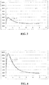
- FIG. 5 illustrates an exemplary temperature profile 500 that can be achieved using the methods and devices described herein.
- a heating element can be implemented in an ablation device to deliver fluid at a controlled and desired temperature to cool an ablation element.
- the temperature of the fluid can be selected such that the ablation element is cooled to a temperature below about 100° C. More preferably, the fluid can be cooled to a temperature between about 20° C and 100° C. Still more preferably, the fluid can be cooled to a temperature between about 37° C and 100° C.
- the ablation element can be cooled to a temperature of about 60° C. Regulating the temperature of the ablation element to this level can prevent the desiccation and impedance rise associated with heating above 100° C, but can also allow for deeper therapeutic heating using a lower RF power level.
- the profile 500 shows that tissue to a depth of 5 mm can be heated above 50° C with no tissue rising above about 80° C. While 60° C is illustrated as an example, any temperature between about 37° C and 100° C can be selected. For example, a temperature of 40, 50, 60, 70, 80, or 90° C can be selected.
- the selection of the fluid temperature (which can approximate the ablation element temperature because the flowing fluid can cool the ablation element to approximately the same temperature) and RF power level can be coordinated such that a treatment lesion of a desired depth is created without heating any portion of the tissue above about 100° C.
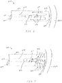
- FIG. 6 illustrates an ablation device 600 according to the invention.
- the device 600 includes an elongate body, which can be rigid or flexible and can be formed from a variety of biocompatible materials.
- the elongate body 602 can be a flexible catheter body, or can be a rigid body disposed at a distal end of a catheter used to introduce the elongate body 602 to a treatment site.
- the elongate body 602 includes an inner lumen 604 extending therethrough that is configured to provide a passage for fluid flow through the elongate body.
- the particular size of the elongate body can depend on a variety of factors including the type and location of tissue to be treated, etc.
- a very small elongate body can be utilized to access the heart of a patient.
- an appropriately sized elongate body can be, for example, a catheter having a diameter of about 8 French ("French" is a unit of measure used in the catheter industry to describe the size of a catheter and is equal to three times the diameter of the catheter in millimeters).
- the elongate body can be formed from a conductive material such that the elongate body can conduct electrical energy along its length to an ablation element disposed thereon.
- the elongate body can be formed from, or coated in, an insulating material and any electrical communication between any components coupled thereto can be accomplished through electrical connections running along or within the elongate body.
- the elongate body 602 also includes an ablation electrode 606 disposed along a length thereof adjacent to its distal end. As shown in the figure, according to the invention the ablation electrode 606 is positioned at the distal end of the elongate body 602.
- the ablation electrode 606 can be formed from a variety of materials suitable for conducting current. Any metal or metal salt may be used. Aside from stainless steel, exemplary metals include platinum, gold, or silver, and exemplary metal salts include silver/silver chloride. In one embodiment, the electrode can be formed from silver/silver chloride. It is known that metal electrodes assume a voltage potential different from that of surrounding tissue and/or liquid.
- a metal salt such as silver/silver chloride has a high exchange current density. As a result, a large amount of current can be passed through such an electrode into tissue with only a small voltage drop, thereby minimizing energy dissipation at this interface.
- an electrode formed from a metal salt such as silver/silver chloride can reduce excessive energy generation at the tissue interface and thereby produce a more desirable therapeutic temperature profile, even where there is no liquid flow about the electrode.
- the ablation electrode 606 is disposed at a distal end of the elongate body 602.
- the ablation electrode 606 forms a blunt distal tip of the device 600.
- the ablation electrode 606 is configured to press against, or be positioned adjacent to, a tissue wall without penetrating into the tissue wall.
- the ablation electrode 606 is formed from a non-porous material or, in examples not according to the invention, an ablation element 606 can have one or more outlet ports or pores formed therein that provide fluid communication between the inner lumen and the tissue and/or fluids surrounding the ablation element.
- the inner lumen of the elongate body 602 includes a delivery lumen 608 configured to provide a passage for fluid flow from the proximal end to the distal end, and a return lumen formed by the annular space between the delivery lumen 608 and the inner wall of the inner lumen 604.
- the return lumen is configured to receive fluid at a distal end thereof and deliver the fluid back to the proximal end of the elongate body 602. This allows fluid to be circulated through the elongate body without the need to release the fluid to the surrounding tissue.
- the delivery lumen 608 can be formed from a variety of materials that are rigid, flexible, polymeric, metallic, conductive, or insulating.
- the delivery lumen 608 is positioned within the inner lumen 604 of the elongate body 602 such that the delivery lumen does not move with respect to the elongate body, or can be allowed to float freely within the elongate body 602.
- the delivery lumen 608 is a hollow tube disposed within the inner lumen of the elongate body.
- the return lumen is a separate hollow tube disposed within the inner lumen 604 of the elongate body.
- the delivery lumen 608 houses a heating assembly or heater element 612 disposed adjacent to a distal end of the delivery lumen and configured to heat fluid flowing through the delivery lumen.
- the heating assembly 612 can be connected to a power supply and controller coupled to the proximal end of the elongate body 602.
- a number of heating assemblies can be utilized to heat fluid flowing through the delivery lumen 608, including those described in U.S. Patent No. 6,328,735 to Curley et al. , and U.S. Pat. Appl. No. 13/445,036 , entitled “Methods and Devices for Heating Fluid in Fluid Enhanced Ablation Therapy," published as US 2012-0265190 A1 , filed concurrently herewith.
- the heater element 612 can be a resistive coil disposed within the delivery lumen 608.
- a heating assembly 612 formed from one or more wires suspended in the delivery lumen 608 that can be used to pass RF electrical energy through the fluid flowing through the delivery lumen, thereby heating the fluid due to its inherent electrical resistivity.
- the delivery lumen 608 houses a temperature sensor 614 configured to detect the temperature of the fluid flowing through the delivery lumen 608 after it is heated by the heating assembly 612.
- the temperature sensor 614 is, in some embodiments, positioned distal to the heating assembly 612, and is separated from the heating assembly by a distance sufficient to allow mixing of the fluid after passing through the heating assembly (e.g., about 1 mm).
- the temperature sensor 614 can have a variety of forms and, in some embodiments, can be a fine-wire thermocouple.
- the temperature sensor 614 can be connected to a controller that can utilize the detected fluid temperature to regulate the heating assembly 612.
- a fluid e.g., saline
- a fluid can be pumped through the delivery lumen 608 from a proximal end thereof to a distal end that is positioned adjacent to the ablation element 606.
- the fluid can pass by the heating assembly 612 and be heated to a desired temperature, e.g., any temperature below 100° C, or any temperature between about 40 and about 90° C, or between about 50 and about 80° C, or between about 60 and about 70° C.
- an additional temperature sensor (not shown) can be positioned in the delivery lumen 608 at a position proximal to the heating assembly 612 in order to determine the initial temperature of the fluid flowing through the delivery lumen 608 (and thereby determine a power output needed for the heating assembly 612).
- the fluid can mix and exit the delivery lumen 608 near the distal end of the elongate body 602 adjacent to the ablation element 606.
- the fluid can contact an inner surface of the ablation element and subsequently be directed back toward the proximal end of the elongate body 602 through the return lumen.
- the movement of the fluid can convect heat away from the ablation element 606, thereby regulating its temperature. Given a sufficient flow rate, the ablation element 606 can be regulated to about the same temperature of the fluid exiting the delivery lumen 608.
- the device 600 can also include an external temperature sensor 618 disposed on a distal end of the device 600.
- the temperature sensor 618 can be recessed within the ablation element 606 such that it does not protrude from a distal end thereof.
- the temperature sensor 618 can be positioned inside the inner lumen 604 touching a proximal surface of the ablation element 606. Regardless of its position, the temperature sensor 618 can be configured to detect the temperature at the interface between the ablation element 606 and a tissue surface 620. Detecting the temperature at this location can confirm that the ablation element 606 is being cooled to the temperature of the fluid flowing from the delivery lumen 608.
- FIG. 7 illustrates an example embodiment of an ablation device not according to the invention having an open-loop flow, as opposed to the closed-loop flow shown in FIG. 6 .
- the device 700 can include several components common to the device of FIG. 6 .
- the device 700 can include an elongate body 602 having an inner lumen 604, a delivery lumen 608 disposed within the inner lumen 604 and having its own inner lumen 610, a heating assembly 612 and temperature sensor 614 housed within the inner lumen 610, and, in some embodiments, one or more additional temperature sensors, such as the temperature sensor 618.
- the device 700 differs from the device 600 in that it includes an ablation element 702 having a plurality of outlet ports or pores formed therein that communicate between an inner surface and an outer surface of the ablation element.
- an ablation element 702 having a plurality of outlet ports or pores formed therein that communicate between an inner surface and an outer surface of the ablation element.
- the device 700 can, in some embodiments, remove the separate delivery lumen 608 and simply pump fluid in a single direction through the inner lumen 604 of the elongate body 602.
- the heating assembly and any temperature sensors can be disposed within the inner lumen 604 of the elongate body 602.
- the devices shown in FIGS. 6 and 7 can both be used to administer ablation therapy that prevents the overheating of tissue while producing therapeutic treatment at greater depths than previously possible.
- the temperature of the fluid introduced from the delivery lumen 608 is sufficiently high (e.g., 70° C and above)
- it can be undesirable to allow the fluid to flow into the bloodstream or tissue surrounding the ablation device. Fluid at that temperature can, in some cases, damage tissue or cause blood clots to form.
- the devices described above can be utilized in a variety of procedures requiring ablation of tissue within the body.
- the devices and methods disclosed herein can be particularly useful in cardiac ablation.
- Procedures for the treatment of atrial fibrillation and atrial flutter, such as the Maze Procedure often require ablating a large amount of the cardiac anatomy in locations where the tissue walls have variable thickness.
- the devices of the present invention allow operators to ablate a variety of tissue geometries using a minimum level of RF power and without overheating tissue at any depth.
- a device similar to the device 600 can be inserted into a patient's body via an access port or other opening formed through one or more layers of tissue, or via a natural orifice (i.e., endoscopically).
- the device can subsequently be delivered to any treatment site within the body directly, or using existing passageways within the body (e.g., passing the device into the heart through a patient's blood vessels).
- the ablation element of the device can be positioned using the aid of sensing electrodes or other positioning instruments, and the distal tip of the ablation element can be pressed against a tissue wall at a particular location.
- the elongate body and/or ablation element can have a blunt distal end, such that the elongate body and/or ablation element can be pressed against a tissue wall without penetrating through the tissue.
- RF energy can be delivered into the tissue wall while fluid is simultaneously delivered through the elongate body, e.g., through a delivery lumen.
- the fluid can be heated by a heating assembly positioned in a distal portion of the elongate body, e.g., within a distal portion of the delivery lumen.
- the fluid can contact the ablation element and either flow through ports formed in the ablation element or flow back up to the proximal end of the elongate member to convect heat away from the ablation element.
- the delivery of the heated fluid can effectively regulate the temperature of the ablation element to match that of the heated fluid.
- the controlled and elevated operating temperature can allow ablation therapy to be conducted using an efficient level of RF power, and the heating of tissue above a threshold level, e.g., 100° C, can be avoided.
- the devices of the present invention can be equally adapted for use in other areas of a patient's body. As such, the devices described herein can be formed in a variety of sizes and materials appropriate for use in various areas of a patient's body.
- the heating mechanism for producing hyperthermia within the target tissue sufficient to destroy it can include other forms of energy.
- Ultrasonic vibrational energy is known to be absorbed by tissue and converted to heat, as is microwave and light wave electromagnetic energy.
- Alternative examples not according to the invention may employ ultrasonic transducers, microwave antennas, or light wave diffusers as emitters disposed in the distal end of an elongate body.
- Light wave electromagnetic energy can fall in a range spanning visible, near-infrared, infrared, and far-infrared radiation, and can be generated by filaments, arc lamps, lasers of various forms (e.g., diodes, semiconductors, or pumps), or by other means.
- the heating assembly or element described above can have a variety of forms, including a resistive wire for heating the fluid through conduction. Regardless of the type of ablation element utilized, the injection of heated liquid into the elongate body adjacent to the ablation element can aid in regulating its temperature, and using saline heated above room temperature can increase the efficiency of the ablation therapy and allow the use of lower RF power. It is also recognized that the devices described above can be delivered to a treatment site using any standard medical delivery device, depending on the tissue to be treated. Exemplary alternative embodiments can include metallic or nonmetallic needle bodies, sheaths, or introducers.
- the devices disclosed herein can be designed to be disposed after a single use, or they can be designed for multiple uses. In either case, however, the device can be reconditioned for reuse after at least one use.
- Reconditioning can include any combination of the steps of disassembly of the device, followed by cleaning or replacement of particular pieces, and subsequent reassembly.
- the device can be disassembled, and any number of the particular pieces or parts of the device can be selectively replaced or removed in any combination.
- the device can be reassembled for subsequent use either at a reconditioning facility or by a surgical team immediately prior to a surgical procedure.
- reconditioning of a device can utilize a variety of techniques for disassembly, cleaning/replacement, and reassembly.
- the devices disclosed herein may be disassembled partially or completely.
- the elongate body 602 of the medical device 600 shown in FIG. 6 may be decoupled from any control handle or other connected component, or the elongate body 602 can be separated from the ablation element and/or any delivery lumen extending therethrough.
- the heating assembly or element 612 and the temperature sensor 614 can be separated from the delivery lumen 608 and/or elongate body 602 for cleaning and/or replacement.
- the devices described herein will be processed before surgery.
- a new or used instrument can be obtained and, if necessary, cleaned.
- the instrument can then be sterilized.
- the instrument is placed in a closed and sealed container, such as a plastic or TYVEK bag.
- the container and its contents can then be placed in a field of radiation that can penetrate the container, such as gamma radiation, x-rays, or high-energy electrons.
- the radiation can kill bacteria on the instrument and in the container.
- the sterilized instrument can then be stored in the sterile container.
- the sealed container can keep the instrument sterile until it is opened in the medical facility.
- the device is sterilized. This can be done by any number of ways known to those skilled in the art including beta or gamma radiation, ethylene oxide, steam, and a liquid bath (e.g., cold soak).
- the materials selected for use in forming components such as the elongate body may not be able to withstand certain forms of sterilization, such as gamma radiation. In such a case, suitable alternative forms of sterilization can be used, such as ethylene oxide.
Description
- The present application relates generally to the control of ablation therapy. More particularly, this application relates to improved devices and methods for controlling ablation therapy.
- The use of thermal energy to destroy bodily tissue can be applied to a variety of therapeutic procedures, including the treatment of cardiac arrhythmias, such as atrial fibrillation. In such a procedure, thermal energy can be imparted to the arrhythmogenic myocardium using various forms of energy, such as radio frequency electrical energy, microwave or light wave electromagnetic energy, or ultrasonic vibrational energy. Radio frequency (RF) ablation, for example, can be effected by placing a catheter within the heart and pressing an emitting electrode disposed on the catheter against the heart wall near the region of the myocardium that is causing the arrhythmia. High frequency electrical current can be passed into the tissue between closely spaced emitting electrodes or between the emitting electrode and a larger, common electrode located remotely from the tissue to be heated. The energy can heat the myocardium to a temperature that will cause necrosis (e.g., a temperature above about 50° C).
- One embodiment of a prior art ablation catheter is shown in
FIG. 1 . Thecatheter 100 includes a plurality ofsensing electrodes 102 disposed thereon that are used to detect electrical activity in the heart. The measurement of electrical activity can be used to detect the arrhythmogenic tissue and guide the placement of the catheter. The catheter also includes a large electrode orother ablation element 104 disposed on the distal end thereof that is effective to transmit RF electrical energy into themyocardium 106. In use, theelectrode 104 on the distal tip of thecatheter 100 is placed against the surface of themyocardium 106 in a desired location, and the electrode is subsequently activated to heat the tissue. - Prior art ablation catheters have a number of disadvantages. For example, using the above techniques, maximum heating often occurs at or near the interface between the
catheter electrode 104 and thetissue 106. In RF ablation, for example, maximum heating can occur in the tissue immediately adjacent to the emitting electrode. Furthermore, as these techniques are increasingly used in areas having thicker tissue walls, the RF power level must be increased to effect heating at greater depths within the tissue. This can result in even higher levels of heating at the interface between the electrode and the tissue. As described in more detail below, these high levels of heating can reduce the conductivity of the tissue, effectively preventing the transmission of further energy into the tissue. In addition, some levels of heating can produce dangerous medical complications for a patient, including, for example, clots that can result from overheating surrounding blood - Documents
US6328735 B1 ,US2008086073 A1 ,WO9634569 A1 WO9829068 A1 US5653692 A ,EP0895756 A1 ,WO03096871 A2 US2006085054 A1 disclose relevant background art. - Accordingly, there is a need for improved methods and devices for controlling ablation therapy.
- The invention is defined in the appended
independent claim 1. Preferred embodiments are described in the dependent claims. The present disclosure generally provides devices and methods for controlling ablation therapy. In particular, the devices and methods described herein permit regulation of the temperature of an ablation element being used to emit ablative energy into tissue. By controlling the temperature of the ablation element, the undesirable effects associated with overheating the tissue can be avoided. This, in turn, can allow a greater amount of tissue to be treated using a lower amount of ablative energy, thereby reducing the risk of unintended damage to tissue. - According to the invention, an ablation device is provided that includes an elongate body having proximal and distal ends, and an inner lumen extending therethrough. The device further includes an ablation electrode positioned at the distal end of the elongate body, the ablation electrode being configured to heat surrounding tissue. The inner lumen of the elongate body is configured to receive fluid therein such that the fluid flows to the distal end of the elongate body. The device further includes a heater element disposed within the inner lumen adjacent to a distal end thereof. The heater element is configured to heat fluid flowing through the inner lumen.
- According to the invention, the elongate body and the ablation element are non-porous such that fluid is preventing from flowing therethrough. The inner lumen includes a delivery lumen, as well as a return lumen such that fluid can flow distally through the delivery lumen to the distal end, and then flow proximally through the return lumen to the proximal end of the elongate body. In examples not according to the invention, the elongate body can include one or more outlet ports formed through a sidewall thereof adjacent to the distal end thereof, the outlet ports being configured to allow fluid to flow from the inner lumen and into surrounding tissue.
- In certain embodiments, the device further includes a temperature sensor disposed on a distal end of the ablation electrode to sample a temperature at the interface between the ablation element and a tissue wall. In examples not according to the invention, the temperature sensor can be recessed within the ablation element such that it does not protrude from a distal end thereof. In other embodiments still, the temperature sensor can be disposed within the inner lumen of the elongate body and in contact with the ablation element.
- In some embodiments, the device includes a different temperature sensor positioned adjacent to the distal end of the inner lumen at a location distal to the heater element in order to sample a temperature of fluid heated by the heater element. Still further, in examples not according to the invention, the device can include a temperature sensor positioned proximal to the heater element within the inner lumen to sample the temperature of fluid flowing through the inner lumen.
- The heater element can have a variety of forms. In some embodiments, the heater element can include at least one wire extending through the inner lumen and configured to pass Radio Frequency (RF) electrical energy through fluid flowing through the inner lumen. In other embodiments, the heater element can be a resistive element disposed within the inner lumen.
- According to the invention, the ablation electrode forms a blunt distal tip of the elongate body that is configured to contact tissue without penetrating through the tissue. examples not according to the invention, the ablation element can have a variety of other shapes.
- In an aspect of the disclosure that does not form part of the invention, a method of ablating tissue is provided that includes positioning a blunt distal portion of an elongate body in contact with tissue, and delivering ablative energy to the tissue through an ablation element while simultaneously delivering fluid through the elongate body where the fluid is heated by a heater element disposed in a distal portion of the elongate body. The fluid can be heated to control the ablation therapy provided to the tissue by the ablation element.
- The blunt distal portion of the elongate body does not penetrate the tissue when positioned in contact therewith, but rather abuts against a surface of the tissue. The ablation element is positioned at that distal end of the elongate body, such that the distal end of the elongate body is positioned in contact with tissue.
- Delivering fluid through the elongate body can include forcing fluid through an inner lumen disposed within the elongate body. The heater element is disposed within the inner lumen. The method can further include receiving fluid delivered through the elongate body at a proximal end thereof, e.g., such that the fluid circulates through the elongate body without exiting at the distal end of the elongate body. In examples not according to the invention, the fluid delivered through the elongate body can flow through one or more outlet ports formed in the ablation element into the surrounding tissue or fluid.
- The method can further include detecting a temperature of the tissue in contact with the blunt distal portion of the elongate body using a temperature sensor disposed on a distal end of the elongate body. The method can include detecting the temperature of the fluid delivered through the elongate body using a temperature sensor disposed distal to the heater element.
- The aspects and embodiments of the invention described above will be more fully understood from the following detailed description taken in conjunction with the accompanying drawings, in which:
-
FIG. 1 is a diagram of one embodiment of a prior art ablation device; -
FIG. 2 is a chart showing a temperature profile created in tissue by the prior art ablation device ofFIG. 1 ; -
FIG. 3 is a chart showing a temperature profile created in tissue by a prior art ablation device cooled by unheated fluid; -
FIG. 4 is a chart showing a temperature profile created in tissue by the device ofFIG. 3 following an increase in ablative energy level; -
FIG. 5 is a chart showing a temperature profile created in tissue using one embodiment of an ablation device of the present invention; -
FIG. 6 is a side view of an ablation device according to the invention having a closed loop flow pattern; and -
FIG. 7 is a side view of an exemplary ablation device having an open loop flow pattern. - Certain exemplary embodiments will now be described to provide an overall understanding of the principles of the devices and methods disclosed herein. One or more examples of these embodiments are illustrated in the accompanying drawings. Those skilled in the art will understand that the devices and methods specifically described herein and illustrated in the accompanying drawings are non-limiting exemplary embodiments and that the scope of the present invention is defined solely by the claims.
- The terms "about" and "approximately" used for any numerical values or ranges indicate a suitable dimensional tolerance that allows the composition, part, or collection of elements to function for its intended purpose as described herein. These terms generally indicate a ±10% variation about a central value. Components described herein as being coupled may be directly coupled, or they may be indirectly coupled via one or more intermediate components. The recitation of any ranges of values herein is merely intended to serve as a shorthand method of referring individually to each separate value falling within the range, unless otherwise indicated herein, and each separate value is incorporated into the specification as if it were individually recited. All unclaimed methods described herein can be performed in any suitable order unless otherwise indicated herein or otherwise clearly contradicted by context. No language in the specification should be construed as indicating any non-claimed element as essential to the practice of the invention. Further, to the extent the term "saline" is used in conjunction with any embodiment herein, such embodiment is not limited to the use of "saline" as opposed to another fluid unless explicitly indicated. Other fluids can typically be used in a similar manner.
- As described above, conventional ablation techniques using a device similar to the
ablation catheter 100 ofFIG. 1 can produce maximal heating of tissue at the interface between the ablation element, such aselectrode 104, and the tissue, such asmyocardium 106. Use of such a device can produce thetemperature profile 200 ofFIG. 2 that illustrates the temperature (in degrees Celsius) as a function of the depth (in millimeters) from the tissue surface. As shown in the figure, theablation catheter 100 can create a therapeutically treated lesion in tissue that is 1 mm deep. That is, the depth to which the tissue is heated above 50° C is 1mm. A temperature of 50° C is used herein as an example of a threshold for determining when a particular volume of tissue has been therapeutically treated, i.e., has received a thermal dose sufficient to cause necrosis within the volume (see Nath, S. and Haines, D. E., Prog. Card. Dis. 37(4):185-205 (1995) (Nath et al.)). However, this number is provided by way of example only, as the literature contains a number of different methodologies for determining thermal dose administration, any of which can be utilized with the methods and devices of the present disclosure. - Referring back to
FIG. 2 , the shallow treatment depth produced by the priorart ablation catheter 100 is often only effective for use with superficial arrhythmogenic tissue or, for example, in regions of the heart where the wall is very thin (e.g., thin atrial walls). As the use of ablation in the treatment of atrial fibrillation and other cardiac conditions has increased over time, ablation therapy has been used in areas having much thicker tissue walls. One method for increasing the depth to which an ablation catheter can heat is to cool the surface of the ablation element, e.g., theelectrode 104. To accomplish this, a fluid can be pumped down the ablation catheter to contact the ablation element disposed adjacent to the distal end of the catheter. In some cases, the fluid can contact a rear surface of the ablation element and return up the catheter body. In other cases, however, the fluid can flow out of the ablation catheter through one or more ports or pores formed in the ablation element itself. - In either case, fluid (e.g., saline) can be introduced into the ablation catheter at room temperature and is often heated to near body temperature by the surrounding blood as the fluid moves through the body toward the distal end of the catheter. The flowing body-temperature fluid can cool and constrain the ablation element to a temperature that is about body temperature, or 37° C.
- An exemplary temperature profile created by such a device is shown in
FIG. 3 . As theprofile 300 illustrates, contacting the ablation element with body-temperature fluid can be effective to reduce the heating that occurs at the interface between the ablation element and the tissue wall. However, the cooling can also be effective to reduce the entire heating field to such a degree that the effectiveness of the ablation therapy is reduced, i.e., only a very small portion of tissue is heated above the desired therapeutic temperature of 50° C. This same effect can also be seen in areas of the heart (or other organs) where blood vessels or arteries produce effective localized cooling by moving blood past the treatment site. For example, in atrial fibrillation it can be necessary to perform ablation near the coronary sinus, and the large amount of blood flow in this area can effectively cool the heating fields created by any ablation devices. - To compensate for this cooling effect, the level of RF power used to heat the tissue can be increased. An increase in RF power in combination with fluid cooling of the ablation element can, for example, produce the
temperature profile 400 shown inFIG. 4 . The increase in power can have the positive effect of increasing the depth of therapeutic treatment (e.g., the depth of therapeutic treatment increases to 2 mm), but comes at the cost of producing a higher maximum temperature within the tissue. Furthermore, the position of the maximum temperature can be shifted into the tissue as a result of the cooling of the ablation element. Because this maximum temperature can no longer be directly observed due to its position at depth, it can be difficult to control the balance between the amount of RF heating and the amount of cooling provided by the fluid. In such a situation, temperatures within the tissue can exceed 100° C in some locations, as shown inFIG. 4 . Exceeding 100° C can produce a number of undesirable effects. For example, above 100° C tissue can desiccate, or dry up, and overheat. This can produce charring and lead to an increase in the impedance of the tissue. As the impedance increases, the amount of electrical energy that can pass through the tissue decreases. Accordingly, impedance rises can effectively stop any further ablation therapy since energy is no longer transferred deeper into the tissue. Still further, such high temperatures can also cause superheating of any fluid in the tissue. In some cases, impedance pops or the explosive phase change of superheated fluid to steam can occur. These small explosions can cause damage in the tissue wall and potentially lead to serious medical complications (e.g., perforations in the heart wall, etc.). - To address these issues, methods and devices are provided herein to control the temperature and power level of an ablation element to thereby prevent undesirable temperature spikes while maintaining the depth of the treatment lesion created during ablation therapy.
FIG. 5 illustrates anexemplary temperature profile 500 that can be achieved using the methods and devices described herein. In one embodiment, a heating element can be implemented in an ablation device to deliver fluid at a controlled and desired temperature to cool an ablation element. The temperature of the fluid can be selected such that the ablation element is cooled to a temperature below about 100° C. More preferably, the fluid can be cooled to a temperature between about 20° C and 100° C. Still more preferably, the fluid can be cooled to a temperature between about 37° C and 100° C. - For example, and as shown in the figure, the ablation element can be cooled to a temperature of about 60° C. Regulating the temperature of the ablation element to this level can prevent the desiccation and impedance rise associated with heating above 100° C, but can also allow for deeper therapeutic heating using a lower RF power level. For example, the
profile 500 shows that tissue to a depth of 5 mm can be heated above 50° C with no tissue rising above about 80° C. While 60° C is illustrated as an example, any temperature between about 37° C and 100° C can be selected. For example, a temperature of 40, 50, 60, 70, 80, or 90° C can be selected. The selection of the fluid temperature (which can approximate the ablation element temperature because the flowing fluid can cool the ablation element to approximately the same temperature) and RF power level can be coordinated such that a treatment lesion of a desired depth is created without heating any portion of the tissue above about 100° C. - A number of different devices and methods can be employed to heat the cooling fluid to a desired temperature.
FIG. 6 illustrates anablation device 600 according to the invention. Thedevice 600 includes an elongate body, which can be rigid or flexible and can be formed from a variety of biocompatible materials. For example, theelongate body 602 can be a flexible catheter body, or can be a rigid body disposed at a distal end of a catheter used to introduce theelongate body 602 to a treatment site. Theelongate body 602 includes aninner lumen 604 extending therethrough that is configured to provide a passage for fluid flow through the elongate body. Further, the particular size of the elongate body can depend on a variety of factors including the type and location of tissue to be treated, etc. By way of example only, in one embodiment, a very small elongate body can be utilized to access the heart of a patient. In such an embodiment, an appropriately sized elongate body can be, for example, a catheter having a diameter of about 8 French ("French" is a unit of measure used in the catheter industry to describe the size of a catheter and is equal to three times the diameter of the catheter in millimeters). The elongate body can be formed from a conductive material such that the elongate body can conduct electrical energy along its length to an ablation element disposed thereon. Alternatively, the elongate body can be formed from, or coated in, an insulating material and any electrical communication between any components coupled thereto can be accomplished through electrical connections running along or within the elongate body. - The
elongate body 602 also includes anablation electrode 606 disposed along a length thereof adjacent to its distal end. As shown in the figure, according to the invention theablation electrode 606 is positioned at the distal end of theelongate body 602. Theablation electrode 606 can be formed from a variety of materials suitable for conducting current. Any metal or metal salt may be used. Aside from stainless steel, exemplary metals include platinum, gold, or silver, and exemplary metal salts include silver/silver chloride. In one embodiment, the electrode can be formed from silver/silver chloride. It is known that metal electrodes assume a voltage potential different from that of surrounding tissue and/or liquid. Passing a current through this voltage difference can result in energy dissipation at the electrode/tissue interface, which can exacerbate excessive heating of the tissue near the electrodes. One advantage of using a metal salt such as silver/silver chloride is that it has a high exchange current density. As a result, a large amount of current can be passed through such an electrode into tissue with only a small voltage drop, thereby minimizing energy dissipation at this interface. Thus, an electrode formed from a metal salt such as silver/silver chloride can reduce excessive energy generation at the tissue interface and thereby produce a more desirable therapeutic temperature profile, even where there is no liquid flow about the electrode. - According to the invention, the
ablation electrode 606 is disposed at a distal end of theelongate body 602. Theablation electrode 606 forms a blunt distal tip of thedevice 600. As such, theablation electrode 606 is configured to press against, or be positioned adjacent to, a tissue wall without penetrating into the tissue wall. Furthermore, theablation electrode 606 is formed from a non-porous material or, in examples not according to the invention, anablation element 606 can have one or more outlet ports or pores formed therein that provide fluid communication between the inner lumen and the tissue and/or fluids surrounding the ablation element. - According to the invention, the inner lumen of the
elongate body 602 includes adelivery lumen 608 configured to provide a passage for fluid flow from the proximal end to the distal end, and a return lumen formed by the annular space between thedelivery lumen 608 and the inner wall of theinner lumen 604. The return lumen is configured to receive fluid at a distal end thereof and deliver the fluid back to the proximal end of theelongate body 602. This allows fluid to be circulated through the elongate body without the need to release the fluid to the surrounding tissue. Similar to theelongate body 602, thedelivery lumen 608 can be formed from a variety of materials that are rigid, flexible, polymeric, metallic, conductive, or insulating. Further, thedelivery lumen 608 is positioned within theinner lumen 604 of theelongate body 602 such that the delivery lumen does not move with respect to the elongate body, or can be allowed to float freely within theelongate body 602. In some embodiments, thedelivery lumen 608 is a hollow tube disposed within the inner lumen of the elongate body. In addition, in certain embodiments, the return lumen is a separate hollow tube disposed within theinner lumen 604 of the elongate body. - According to the invention, the
delivery lumen 608 houses a heating assembly orheater element 612 disposed adjacent to a distal end of the delivery lumen and configured to heat fluid flowing through the delivery lumen. Theheating assembly 612 can be connected to a power supply and controller coupled to the proximal end of theelongate body 602. A number of heating assemblies can be utilized to heat fluid flowing through thedelivery lumen 608, including those described inU.S. Patent No. 6,328,735 to Curley et al. , andU.S. Pat. Appl. No. 13/445,036 , entitled "Methods and Devices for Heating Fluid in Fluid Enhanced Ablation Therapy," published asUS 2012-0265190 A1 , filed concurrently herewith. For example, theheater element 612 can be a resistive coil disposed within thedelivery lumen 608. In other embodiments, however, aheating assembly 612 formed from one or more wires suspended in thedelivery lumen 608 that can be used to pass RF electrical energy through the fluid flowing through the delivery lumen, thereby heating the fluid due to its inherent electrical resistivity. - In certain embodiments, the
delivery lumen 608 houses atemperature sensor 614 configured to detect the temperature of the fluid flowing through thedelivery lumen 608 after it is heated by theheating assembly 612. For this reason, thetemperature sensor 614 is, in some embodiments, positioned distal to theheating assembly 612, and is separated from the heating assembly by a distance sufficient to allow mixing of the fluid after passing through the heating assembly (e.g., about 1 mm). Thetemperature sensor 614 can have a variety of forms and, in some embodiments, can be a fine-wire thermocouple. Thetemperature sensor 614 can be connected to a controller that can utilize the detected fluid temperature to regulate theheating assembly 612. - In use, a fluid (e.g., saline) can be pumped through the
delivery lumen 608 from a proximal end thereof to a distal end that is positioned adjacent to theablation element 606. The fluid can pass by theheating assembly 612 and be heated to a desired temperature, e.g., any temperature below 100° C, or any temperature between about 40 and about 90° C, or between about 50 and about 80° C, or between about 60 and about 70° C. In some embodiments, an additional temperature sensor (not shown) can be positioned in thedelivery lumen 608 at a position proximal to theheating assembly 612 in order to determine the initial temperature of the fluid flowing through the delivery lumen 608 (and thereby determine a power output needed for the heating assembly 612). After being heated by theheating assembly 612, the fluid can mix and exit thedelivery lumen 608 near the distal end of theelongate body 602 adjacent to theablation element 606. As shown by theflow direction arrows 616, the fluid can contact an inner surface of the ablation element and subsequently be directed back toward the proximal end of theelongate body 602 through the return lumen. The movement of the fluid can convect heat away from theablation element 606, thereby regulating its temperature. Given a sufficient flow rate, theablation element 606 can be regulated to about the same temperature of the fluid exiting thedelivery lumen 608. - In order to confirm the effectiveness of the temperature regulation, the
device 600 can also include anexternal temperature sensor 618 disposed on a distal end of thedevice 600. In some embodiments, thetemperature sensor 618 can be recessed within theablation element 606 such that it does not protrude from a distal end thereof. In still other embodiments in which theablation element 606 is formed from a metal or other thermally conductive material, thetemperature sensor 618 can be positioned inside theinner lumen 604 touching a proximal surface of theablation element 606. Regardless of its position, thetemperature sensor 618 can be configured to detect the temperature at the interface between theablation element 606 and atissue surface 620. Detecting the temperature at this location can confirm that theablation element 606 is being cooled to the temperature of the fluid flowing from thedelivery lumen 608. -
FIG. 7 illustrates an example embodiment of an ablation device not according to the invention having an open-loop flow, as opposed to the closed-loop flow shown inFIG. 6 . As shown in the figure, thedevice 700 can include several components common to the device ofFIG. 6 . For example, thedevice 700 can include anelongate body 602 having aninner lumen 604, adelivery lumen 608 disposed within theinner lumen 604 and having its owninner lumen 610, aheating assembly 612 andtemperature sensor 614 housed within theinner lumen 610, and, in some embodiments, one or more additional temperature sensors, such as thetemperature sensor 618. - The
device 700 differs from thedevice 600 in that it includes anablation element 702 having a plurality of outlet ports or pores formed therein that communicate between an inner surface and an outer surface of the ablation element. As a result, when fluid is introduced into theinner lumen 604 adjacent to theablation element 702, the fluid can flow through theablation element 702 and into the body cavity surrounding thedevice 700. The resulting open-loop flow pattern is illustrated by flow direction arrows 704. As a result of the open-loop flow pattern, thedevice 700 can, in some embodiments, remove theseparate delivery lumen 608 and simply pump fluid in a single direction through theinner lumen 604 of theelongate body 602. In such an embodiment, the heating assembly and any temperature sensors can be disposed within theinner lumen 604 of theelongate body 602. - The devices shown in
FIGS. 6 and 7 can both be used to administer ablation therapy that prevents the overheating of tissue while producing therapeutic treatment at greater depths than previously possible. In some embodiments, however, it can be preferable to utilize the closed-loop device 600 rather than the open-loop device 700. For example, in embodiments where the temperature of the fluid introduced from thedelivery lumen 608 is sufficiently high (e.g., 70° C and above), it can be undesirable to allow the fluid to flow into the bloodstream or tissue surrounding the ablation device. Fluid at that temperature can, in some cases, damage tissue or cause blood clots to form. Accordingly, it can be desirable to collect the heated fluid at the proximal end of the device, rather than introduce the fluid into the patient's body. This can vary by location and specific anatomy of the treatment site, however. For example, areas having high blood flow may be able to dissipate the high temperature fluid without risk of developing complications. - The devices described above can be utilized in a variety of procedures requiring ablation of tissue within the body. For example, the devices and methods disclosed herein can be particularly useful in cardiac ablation. Procedures for the treatment of atrial fibrillation and atrial flutter, such as the Maze Procedure, often require ablating a large amount of the cardiac anatomy in locations where the tissue walls have variable thickness. The devices of the present invention allow operators to ablate a variety of tissue geometries using a minimum level of RF power and without overheating tissue at any depth.
- For example, in ablating a thicker wall of the myocardium, a device similar to the
device 600 can be inserted into a patient's body via an access port or other opening formed through one or more layers of tissue, or via a natural orifice (i.e., endoscopically). The device can subsequently be delivered to any treatment site within the body directly, or using existing passageways within the body (e.g., passing the device into the heart through a patient's blood vessels). Once in the vicinity of a desired treatment site, the ablation element of the device can be positioned using the aid of sensing electrodes or other positioning instruments, and the distal tip of the ablation element can be pressed against a tissue wall at a particular location. Further, in many embodiments the elongate body and/or ablation element can have a blunt distal end, such that the elongate body and/or ablation element can be pressed against a tissue wall without penetrating through the tissue. Following positioning, RF energy can be delivered into the tissue wall while fluid is simultaneously delivered through the elongate body, e.g., through a delivery lumen. The fluid can be heated by a heating assembly positioned in a distal portion of the elongate body, e.g., within a distal portion of the delivery lumen. The fluid can contact the ablation element and either flow through ports formed in the ablation element or flow back up to the proximal end of the elongate member to convect heat away from the ablation element. The delivery of the heated fluid can effectively regulate the temperature of the ablation element to match that of the heated fluid. The controlled and elevated operating temperature can allow ablation therapy to be conducted using an efficient level of RF power, and the heating of tissue above a threshold level, e.g., 100° C, can be avoided. - The above exemplary embodiments describe the treatment of cardiac tissue. While this is one contemplated use, the devices of the present invention can be equally adapted for use in other areas of a patient's body. As such, the devices described herein can be formed in a variety of sizes and materials appropriate for use in various areas of a patient's body.
- In addition, those that are knowledgeable in the art will recognize that the heating mechanism for producing hyperthermia within the target tissue sufficient to destroy it can include other forms of energy. Ultrasonic vibrational energy is known to be absorbed by tissue and converted to heat, as is microwave and light wave electromagnetic energy. Alternative examples not according to the invention may employ ultrasonic transducers, microwave antennas, or light wave diffusers as emitters disposed in the distal end of an elongate body. Light wave electromagnetic energy can fall in a range spanning visible, near-infrared, infrared, and far-infrared radiation, and can be generated by filaments, arc lamps, lasers of various forms (e.g., diodes, semiconductors, or pumps), or by other means. Similarly, the heating assembly or element described above can have a variety of forms, including a resistive wire for heating the fluid through conduction. Regardless of the type of ablation element utilized, the injection of heated liquid into the elongate body adjacent to the ablation element can aid in regulating its temperature, and using saline heated above room temperature can increase the efficiency of the ablation therapy and allow the use of lower RF power. It is also recognized that the devices described above can be delivered to a treatment site using any standard medical delivery device, depending on the tissue to be treated. Exemplary alternative embodiments can include metallic or nonmetallic needle bodies, sheaths, or introducers.
- The devices disclosed herein can be designed to be disposed after a single use, or they can be designed for multiple uses. In either case, however, the device can be reconditioned for reuse after at least one use. Reconditioning can include any combination of the steps of disassembly of the device, followed by cleaning or replacement of particular pieces, and subsequent reassembly. In particular, the device can be disassembled, and any number of the particular pieces or parts of the device can be selectively replaced or removed in any combination. Upon cleaning and/or replacement of particular parts, the device can be reassembled for subsequent use either at a reconditioning facility or by a surgical team immediately prior to a surgical procedure. Those skilled in the art will appreciate that reconditioning of a device can utilize a variety of techniques for disassembly, cleaning/replacement, and reassembly.
- For example, the devices disclosed herein may be disassembled partially or completely. In particular, the
elongate body 602 of themedical device 600 shown inFIG. 6 may be decoupled from any control handle or other connected component, or theelongate body 602 can be separated from the ablation element and/or any delivery lumen extending therethrough. Similarly, the heating assembly orelement 612 and thetemperature sensor 614 can be separated from thedelivery lumen 608 and/orelongate body 602 for cleaning and/or replacement. These are exemplary disassembly steps only, as any component of the device can be configured to separate from the device for cleaning and/or replacement. - Preferably, the devices described herein will be processed before surgery. First, a new or used instrument can be obtained and, if necessary, cleaned. The instrument can then be sterilized. In one sterilization technique, the instrument is placed in a closed and sealed container, such as a plastic or TYVEK bag. The container and its contents can then be placed in a field of radiation that can penetrate the container, such as gamma radiation, x-rays, or high-energy electrons. The radiation can kill bacteria on the instrument and in the container. The sterilized instrument can then be stored in the sterile container. The sealed container can keep the instrument sterile until it is opened in the medical facility.
- In many embodiments, it is preferred that the device is sterilized. This can be done by any number of ways known to those skilled in the art including beta or gamma radiation, ethylene oxide, steam, and a liquid bath (e.g., cold soak). In certain embodiments, the materials selected for use in forming components such as the elongate body may not be able to withstand certain forms of sterilization, such as gamma radiation. In such a case, suitable alternative forms of sterilization can be used, such as ethylene oxide.
- One skilled in the art will appreciate further features and advantages of the invention based on the above-described embodiments. Accordingly, the invention is not to be limited by what has been particularly shown and described, except as indicated by the appended claims.
Claims (12)
- An ablation device (600), comprisingan elongate body (602) having proximal and distal ends, and an inner lumen (608) extending therethrough, the inner lumen being configured to receive fluid therein and to deliver fluid to the distal end of the elongate body;an ablation electrode (606) that forms a blunt distal end of the elongate body, the ablation electrode being configured to contact tissue without penetrating through the tissue and to heat surrounding tissue; anda heater element (612) disposed within the inner lumen adjacent to the distal end of the elongate body, the heater element being configured to heat fluid flowing through the inner lumen to a temperature greater than 37° C and less than 100° C,wherein the elongate body is configured such that fluid can circulate through the elongate body and is received back at the proximal end thereof without being released into surrounding tissue.
- The device of claim 1, wherein the inner lumen includes a delivery lumen (608) configured to deliver fluid from the proximal end to the distal end of the elongate body, and a return lume (604) configured to receive fluid delivered to the distal end of the elongate body and to return the fluid to the proximal end of the elongate body.
- The device of claim 1, further comprising a temperature sensor (618) disposed on a distal end of the ablation electrode.
- The device of claim 1, further comprising a temperature sensor (618) disposed within the inner lumen of the elongate body and in contact with the ablation electrode.
- The device of claim 1, wherein the heater element comprises at least one wire extending through the inner lumen and configured to pass RF electrical energy through fluid flowing through the inner lumen.
- The device of claim 1, further comprising a temperature sensor (614) positioned adjacent to the distal end of the inner lumen at a location distal to the heater element.
- The device of claim 2, wherein the fluid delivered to the distal end of the elongate body through the delivery lumen is returned to the proximal end of the elongate body through the return lumen without being released into surrounding tissue.
- The device of claim 2, wherein the return lumen is defined by the annular space between the delivery lumen and an inner wall of the elongate body inner lumen.
- The device of claim 2, wherein the delivery lumen and the return lumen are each separate hollow tubes disposed within the inner lumen of the elongate body.
- The device of claim 2, wherein the delivery lumen is positioned within the inner lumen of the elongate body such that it does not move with respect to the elongate body.
- The device of claim 2, wherein the delivery lumen floats freely within the inner lumen of the elongate body.
- The device of claim 2, wherein the ablation electrode is formed from a non-porous material.
Applications Claiming Priority (2)
| Application Number | Priority Date | Filing Date | Title |
|---|---|---|---|
| US201161474574P | 2011-04-12 | 2011-04-12 | |
| PCT/US2012/033332 WO2012142296A1 (en) | 2011-04-12 | 2012-04-12 | Methods and devices for controlling ablation therapy |
Publications (3)
| Publication Number | Publication Date |
|---|---|
| EP2696790A1 EP2696790A1 (en) | 2014-02-19 |
| EP2696790A4 EP2696790A4 (en) | 2014-11-12 |
| EP2696790B1 true EP2696790B1 (en) | 2021-03-24 |
Family
ID=47006969
Family Applications (8)
| Application Number | Title | Priority Date | Filing Date |
|---|---|---|---|
| EP12771601.7A Active EP2696788B1 (en) | 2011-04-12 | 2012-04-12 | Devices for use of degassed fluids with fluid enhanced ablation devices |
| EP12771876.5A Active EP2696790B1 (en) | 2011-04-12 | 2012-04-12 | Devices for controlling ablation therapy |
| EP12770631.5A Active EP2696786B1 (en) | 2011-04-12 | 2012-04-12 | Devices for remote temperature monitoring in fluid enhanced ablation therapy |
| EP20184347.1A Withdrawn EP3785653A1 (en) | 2011-04-12 | 2012-04-12 | Devices for remote temperature monitoring in fluid enhanced ablation therapy |
| EP21191571.5A Pending EP3932347A1 (en) | 2011-04-12 | 2012-04-12 | Devices for use of degassed fluids with fluid enhanced ablation devices |
| EP19151775.4A Pending EP3498208A1 (en) | 2011-04-12 | 2012-04-12 | Devices for heating fluid in fluid enhanced ablation therapy |
| EP12771331.1A Active EP2696787B1 (en) | 2011-04-12 | 2012-04-12 | Devices for heating fluid in fluid enhanced ablation therapy |
| EP12770537.4A Active EP2696789B1 (en) | 2011-04-12 | 2012-04-12 | Devices for shaping therapy in fluid enhanced ablation |
Family Applications Before (1)
| Application Number | Title | Priority Date | Filing Date |
|---|---|---|---|
| EP12771601.7A Active EP2696788B1 (en) | 2011-04-12 | 2012-04-12 | Devices for use of degassed fluids with fluid enhanced ablation devices |
Family Applications After (6)
| Application Number | Title | Priority Date | Filing Date |
|---|---|---|---|
| EP12770631.5A Active EP2696786B1 (en) | 2011-04-12 | 2012-04-12 | Devices for remote temperature monitoring in fluid enhanced ablation therapy |
| EP20184347.1A Withdrawn EP3785653A1 (en) | 2011-04-12 | 2012-04-12 | Devices for remote temperature monitoring in fluid enhanced ablation therapy |
| EP21191571.5A Pending EP3932347A1 (en) | 2011-04-12 | 2012-04-12 | Devices for use of degassed fluids with fluid enhanced ablation devices |
| EP19151775.4A Pending EP3498208A1 (en) | 2011-04-12 | 2012-04-12 | Devices for heating fluid in fluid enhanced ablation therapy |
| EP12771331.1A Active EP2696787B1 (en) | 2011-04-12 | 2012-04-12 | Devices for heating fluid in fluid enhanced ablation therapy |
| EP12770537.4A Active EP2696789B1 (en) | 2011-04-12 | 2012-04-12 | Devices for shaping therapy in fluid enhanced ablation |
Country Status (9)
| Country | Link |
|---|---|
| US (19) | US20120277737A1 (en) |
| EP (8) | EP2696788B1 (en) |
| JP (14) | JP6189826B2 (en) |
| KR (9) | KR102212427B1 (en) |
| CN (10) | CN106420040B (en) |
| AU (7) | AU2012242845A1 (en) |
| BR (5) | BR112013026176A2 (en) |
| ES (4) | ES2864590T3 (en) |
| WO (5) | WO2012142291A1 (en) |
Families Citing this family (90)
| Publication number | Priority date | Publication date | Assignee | Title |
|---|---|---|---|---|
| US7918795B2 (en) | 2005-02-02 | 2011-04-05 | Gynesonics, Inc. | Method and device for uterine fibroid treatment |
| US11259825B2 (en) | 2006-01-12 | 2022-03-01 | Gynesonics, Inc. | Devices and methods for treatment of tissue |
| US9403029B2 (en) * | 2007-07-18 | 2016-08-02 | Visualase, Inc. | Systems and methods for thermal therapy |
| JP5400784B2 (en) * | 2007-10-09 | 2014-01-29 | ボストン サイエンティフィック リミテッド | Electrophysiological electrode and device comprising electrophysiological electrode |
| WO2009048943A1 (en) | 2007-10-09 | 2009-04-16 | Boston Scientific Scimed, Inc. | Cooled ablation catheter devices and methods of use |
| US8088072B2 (en) | 2007-10-12 | 2012-01-03 | Gynesonics, Inc. | Methods and systems for controlled deployment of needles in tissue |
| BRPI0921421A2 (en) * | 2008-11-06 | 2016-01-05 | Nxthera Inc | prostate therapy system |
| US8262574B2 (en) | 2009-02-27 | 2012-09-11 | Gynesonics, Inc. | Needle and tine deployment mechanism |
| WO2015035249A2 (en) | 2013-09-06 | 2015-03-12 | Procept Biorobotics Corporation | Automated image-guided tissue resection and treatment |
| US8903488B2 (en) | 2009-05-28 | 2014-12-02 | Angiodynamics, Inc. | System and method for synchronizing energy delivery to the cardiac rhythm |
| US8926605B2 (en) | 2012-02-07 | 2015-01-06 | Advanced Cardiac Therapeutics, Inc. | Systems and methods for radiometrically measuring temperature during tissue ablation |
| US8954161B2 (en) | 2012-06-01 | 2015-02-10 | Advanced Cardiac Therapeutics, Inc. | Systems and methods for radiometrically measuring temperature and detecting tissue contact prior to and during tissue ablation |
| US9226791B2 (en) | 2012-03-12 | 2016-01-05 | Advanced Cardiac Therapeutics, Inc. | Systems for temperature-controlled ablation using radiometric feedback |
| US9277961B2 (en) | 2009-06-12 | 2016-03-08 | Advanced Cardiac Therapeutics, Inc. | Systems and methods of radiometrically determining a hot-spot temperature of tissue being treated |
| US10588609B2 (en) | 2010-02-04 | 2020-03-17 | Procept Biorobotics Corporation | Gene analysis and generation of stem cell methods and apparatus |
| US11490957B2 (en) | 2010-06-16 | 2022-11-08 | Biosense Webster (Israel) Ltd. | Spectral sensing of ablation |
| US10314650B2 (en) | 2010-06-16 | 2019-06-11 | Biosense Webster (Israel) Ltd. | Spectral sensing of ablation |
| US20140171806A1 (en) * | 2012-12-17 | 2014-06-19 | Biosense Webster (Israel), Ltd. | Optical lesion assessment |
| EP2627274B1 (en) | 2010-10-13 | 2022-12-14 | AngioDynamics, Inc. | System for electrically ablating tissue of a patient |
| CN106420040B (en) | 2011-04-12 | 2020-08-28 | 热医学公司 | Method and apparatus for heating fluid in fluid enhanced ablation therapy |
| EP3290010B1 (en) | 2011-09-13 | 2021-05-19 | Boston Scientific Scimed, Inc. | Systems for prostate treatment |
| US9078665B2 (en) | 2011-09-28 | 2015-07-14 | Angiodynamics, Inc. | Multiple treatment zone ablation probe |
| WO2013152119A1 (en) | 2012-04-03 | 2013-10-10 | Nxthera, Inc. | Induction coil vapor generator |
| US10022176B2 (en) | 2012-08-15 | 2018-07-17 | Thermedical, Inc. | Low profile fluid enhanced ablation therapy devices and methods |
| US9861336B2 (en) | 2012-09-07 | 2018-01-09 | Gynesonics, Inc. | Methods and systems for controlled deployment of needle structures in tissue |
| US10195467B2 (en) * | 2013-02-21 | 2019-02-05 | Boston Scientific Scimed, Inc. | Ablation catheter system with wireless radio frequency temperature sensor |
| WO2014153082A2 (en) | 2013-03-14 | 2014-09-25 | Nxthera, Inc. | Systems and methods for treating prostate cancer |
| US9610396B2 (en) * | 2013-03-15 | 2017-04-04 | Thermedical, Inc. | Systems and methods for visualizing fluid enhanced ablation therapy |
| US9033972B2 (en) | 2013-03-15 | 2015-05-19 | Thermedical, Inc. | Methods and devices for fluid enhanced microwave ablation therapy |
| US9579118B2 (en) * | 2013-05-01 | 2017-02-28 | Ethicon Endo-Surgery, Llc | Electrosurgical instrument with dual blade end effector |
| PL2859860T3 (en) * | 2013-10-08 | 2017-12-29 | Erbe Elektromedizin Gmbh | Multifunctional instrument |
| AU2014362361B2 (en) | 2013-12-10 | 2019-06-20 | Boston Scientific Scimed, Inc. | Vapor ablation systems and methods |
| US9968395B2 (en) | 2013-12-10 | 2018-05-15 | Nxthera, Inc. | Systems and methods for treating the prostate |
| US10617805B2 (en) | 2014-03-20 | 2020-04-14 | Exploramed Nc7, Inc. | Fluid measuring reservoir for breast pumps |
| US10022183B2 (en) | 2014-04-01 | 2018-07-17 | Innovations In Medicine, Llc | Temperature-responsive irrigated ablation electrode with reduced coolant flow and related methods for making and using |
| EP3160367B1 (en) | 2014-06-30 | 2022-07-13 | PROCEPT BioRobotics Corporation | Fluid jet tissue resection and cold coagulation (aquablation) apparatus |
| RU2712192C2 (en) | 2014-07-31 | 2020-01-24 | Басф Се | Method of producing pyrazoles |
| CN107072591B (en) | 2014-09-05 | 2021-10-26 | 普罗赛普特生物机器人公司 | Physician-controlled tissue ablation in conjunction with treatment mapping of target organ images |
| CN107148245B (en) | 2014-09-05 | 2021-03-09 | 普罗赛普特生物机器人公司 | Method and apparatus for genetic analysis and generation of stem cells |
| WO2016081611A1 (en) | 2014-11-19 | 2016-05-26 | Advanced Cardiac Therapeutics, Inc. | High-resolution mapping of tissue with pacing |
| KR20170107428A (en) | 2014-11-19 | 2017-09-25 | 어드밴스드 카디악 테라퓨틱스, 인크. | Ablation devices, systems and methods of using a high-resolution electrode assembly |
| CA2967829A1 (en) | 2014-11-19 | 2016-05-26 | Advanced Cardiac Therapeutics, Inc. | Systems and methods for high-resolution mapping of tissue |
| JP6757732B2 (en) | 2015-01-29 | 2020-09-23 | ボストン サイエンティフィック サイムド,インコーポレイテッドBoston Scientific Scimed,Inc. | Steam cutting system and method |
| US9636164B2 (en) | 2015-03-25 | 2017-05-02 | Advanced Cardiac Therapeutics, Inc. | Contact sensing systems and methods |
| GB2536690B (en) * | 2015-03-26 | 2017-05-10 | Cook Medical Technologies Llc | Medical ablation system and method with reduced stray heating |
| ES2793350T3 (en) * | 2015-04-08 | 2020-11-13 | Exploramed Nc7 Inc | Fluid measuring tank for breast pumps |
| CN108024803B (en) * | 2015-04-10 | 2021-10-19 | 安吉戴尼克公司 | System and method for irreversible electroporation using thermally controlled electrodes |
| KR102585412B1 (en) | 2015-05-11 | 2023-10-05 | 바스프 에스이 | Process for preparing 4-amino-pyridazines |
| US10702327B2 (en) | 2015-05-13 | 2020-07-07 | Boston Scientific Scimed, Inc. | Systems and methods for treating the bladder with condensable vapor |
| RU2733958C2 (en) | 2016-02-02 | 2020-10-08 | Басф Се | Method for catalytic hydrogenation for producing pyrazoles |
| SG11201807618QA (en) | 2016-03-15 | 2018-10-30 | Epix Therapeutics Inc | Improved devices, systems and methods for irrigated ablation |
| US11172821B2 (en) | 2016-04-28 | 2021-11-16 | Medtronic Navigation, Inc. | Navigation and local thermometry |
| US20170325869A1 (en) * | 2016-05-10 | 2017-11-16 | Covidien Lp | Methods of ablating tissue |
| EP3463141B1 (en) * | 2016-05-25 | 2021-07-07 | Ikomed Technologies Inc. | System for treating unwanted tissue |
| US9743984B1 (en) | 2016-08-11 | 2017-08-29 | Thermedical, Inc. | Devices and methods for delivering fluid to tissue during ablation therapy |
| CN106388933B (en) * | 2016-09-14 | 2017-10-10 | 上海睿刀医疗科技有限公司 | Electrode for irreversible electroporation device |
| WO2018067248A1 (en) * | 2016-10-04 | 2018-04-12 | St. Jude Medical, Cardiology Division, Inc. | Ablation catheter tip |
| EP3537982B1 (en) | 2016-11-11 | 2022-09-07 | Gynesonics, Inc. | Controlled treatment of tissue and dynamic interaction with tissue and/or treatment data and comparison of tissue and/or treatment data |
| WO2018089923A1 (en) | 2016-11-14 | 2018-05-17 | Gynesonics, Inc. | Methods and systems for real-time planning and monitoring of ablation needle deployment in tissue |
| US10905492B2 (en) | 2016-11-17 | 2021-02-02 | Angiodynamics, Inc. | Techniques for irreversible electroporation using a single-pole tine-style internal device communicating with an external surface electrode |
| JP7129980B2 (en) | 2016-12-21 | 2022-09-02 | ボストン サイエンティフィック サイムド,インコーポレイテッド | Steam cautery system and method |
| WO2018129180A1 (en) | 2017-01-06 | 2018-07-12 | Dfine, Inc. | Osteotome with a distal portion for simultaneous advancement and articulation |
| EP4356944A2 (en) | 2017-01-06 | 2024-04-24 | Nxthera, Inc. | Transperineal vapor ablation systems |
| US11147610B2 (en) * | 2017-02-10 | 2021-10-19 | Biosense Webster (Israel) Ltd. | Tissue thickness using pulsed power |
| CN106725827B (en) * | 2017-03-02 | 2023-11-17 | 上海伴诚医疗科技有限公司 | Intracranial hematoma removing hemostat and intracranial hematoma removing hemostatic device |
| EP3614946B1 (en) | 2017-04-27 | 2024-03-20 | EPiX Therapeutics, Inc. | Determining nature of contact between catheter tip and tissue |
| EP3638126A4 (en) | 2017-05-04 | 2021-03-10 | Gynesonics, Inc. | Methods for monitoring ablation progress with doppler ultrasound |
| EP4223243A1 (en) | 2017-06-20 | 2023-08-09 | Aegea Medical Inc. | Induction coil assembly for uterine ablation and method |
| US10058372B1 (en) * | 2017-08-17 | 2018-08-28 | John H. Shadduck | Medical ablation devices and methods |
| CN109549703B (en) * | 2017-09-25 | 2022-04-01 | 上海微创电生理医疗科技股份有限公司 | Cryoablation system and electrophysiology catheter thereof |
| US20190192220A1 (en) * | 2017-12-27 | 2019-06-27 | Medlumics S.L. | Ablation Catheter with a Patterned Textured Active Area |
| EP3755254A1 (en) * | 2018-02-21 | 2020-12-30 | Medtronic, Inc. | Focal pulsed field ablation devices and methods |
| US20190290300A1 (en) * | 2018-03-23 | 2019-09-26 | SPIRATION, INC., d/b/a OLYMPUS RESPIRATORY AMERICA | Rf bipolar steam generation ablation device |
| US11478297B2 (en) * | 2018-03-23 | 2022-10-25 | Avent, Inc. | System and method for controlling energy delivered to an area of tissue during a treatment procedure |
| US11083871B2 (en) | 2018-05-03 | 2021-08-10 | Thermedical, Inc. | Selectively deployable catheter ablation devices |
| EP3801324A4 (en) * | 2018-06-01 | 2022-03-30 | Santa Anna Tech LLC | Multi-stage vapor-based ablation treatment methods and vapor generation and delivery systems |
| US11918277B2 (en) | 2018-07-16 | 2024-03-05 | Thermedical, Inc. | Inferred maximum temperature monitoring for irrigated ablation therapy |
| US11109999B2 (en) * | 2018-07-27 | 2021-09-07 | Cooltech, Llc | Device for removing heat, energy, and/or fluid from a living mammal |
| JP7265014B2 (en) * | 2018-09-14 | 2023-04-25 | 杭州▲くん▼博生物科技有限公司 | High frequency ablation catheter, pulmonary high frequency ablation system, corresponding control method, control device and computer readable storage medium |
| US11937864B2 (en) * | 2018-11-08 | 2024-03-26 | Dfine, Inc. | Ablation systems with parameter-based modulation and related devices and methods |
| AU2019384814B2 (en) * | 2018-11-21 | 2021-11-04 | Buffalo Filter Llc | Method and apparatus for flow |
| CN109481013B (en) * | 2018-12-19 | 2021-05-28 | 南京康友医疗科技有限公司 | Microwave ablation device with thermal field monitoring function |
| WO2020198150A2 (en) * | 2019-03-22 | 2020-10-01 | Stryker Corporation | Systems for ablating tissue |
| US11832873B2 (en) * | 2019-06-14 | 2023-12-05 | Eric Lee | Cannulas for radio frequency ablation |
| WO2021062074A1 (en) * | 2019-09-27 | 2021-04-01 | St. Jude Medical, Cardiology Division, Inc. | Irrigated catheter system including fluid degassing apparatus and methods of using same |
| EP4051150A1 (en) | 2019-10-28 | 2022-09-07 | Boston Scientific Neuromodulation Corporation | Rf electrode cannula |
| JP7334675B2 (en) * | 2020-05-25 | 2023-08-29 | 株式会社デンソー | In-vehicle camera and vehicle control system |
| CN112022326A (en) * | 2020-08-18 | 2020-12-04 | 上海市第十人民医院 | Spray freezing pipe with adjustable scope of action |
| CN112263322A (en) * | 2020-09-29 | 2021-01-26 | 杭州睿笛生物科技有限公司 | Tumor ablation needle with blood coagulation function |
| US20230066333A1 (en) * | 2021-08-24 | 2023-03-02 | Medtronic Holding Company Sàrl | Cooled bipolar radio-frequency ablation probe |
Citations (3)
| Publication number | Priority date | Publication date | Assignee | Title |
|---|---|---|---|---|
| WO1999020191A1 (en) * | 1997-10-22 | 1999-04-29 | Oratec Interventions, Inc. | Split tip electrode catheter |
| WO2003096871A2 (en) * | 2002-05-16 | 2003-11-27 | Patent Max Q (P.M.Q) Ltd. | Multipurpose fluid jet surgical device |
| US20060085054A1 (en) * | 2004-09-09 | 2006-04-20 | Zikorus Arthur W | Methods and apparatus for treatment of hollow anatomical structures |
Family Cites Families (258)
| Publication number | Priority date | Publication date | Assignee | Title |
|---|---|---|---|---|
| GB1582135A (en) * | 1976-07-14 | 1980-12-31 | Ferranti Ltd | Heaters |
| US4424190A (en) | 1982-02-22 | 1984-01-03 | Cordis Dow Corp. | Rigid shell expansible blood reservoir, heater and hollow fiber membrane oxygenator assembly |
| JPS6297971A (en) | 1985-10-21 | 1987-05-07 | 財団法人日本綿業技術・経済研究所 | Treatment agent for spinning cotton yarn |
| JPS62211057A (en) | 1986-03-12 | 1987-09-17 | オリンパス光学工業株式会社 | Ultrasonic vibration treatment apparatus |
| JPH01146539A (en) | 1987-12-03 | 1989-06-08 | Olympus Optical Co Ltd | Ultrasonic treatment apparatus |
| US5549559A (en) | 1990-03-22 | 1996-08-27 | Argomed Ltd. | Thermal treatment apparatus |
| CA2089739A1 (en) | 1990-09-14 | 1992-03-15 | John H. Burton | Combined hyperthermia and dilation catheter |
| US5190538A (en) | 1991-04-22 | 1993-03-02 | Trimedyne, Inc. | Method and apparatus for subjecting a body site to a movable beam of laterally directed laser radiation |
| WO1993008755A1 (en) * | 1991-11-08 | 1993-05-13 | Ep Technologies, Inc. | Ablation electrode with insulated temperature sensing elements |
| IT1251997B (en) * | 1991-11-11 | 1995-05-27 | San Romanello Centro Fond | RADIANT DEVICE FOR HYPERTHERMIA |
| US6277112B1 (en) | 1996-07-16 | 2001-08-21 | Arthrocare Corporation | Methods for electrosurgical spine surgery |
| JP3774477B2 (en) | 1992-02-10 | 2006-05-17 | アロカ株式会社 | Surgical device |
| US5333603A (en) | 1992-02-25 | 1994-08-02 | Daniel Schuman | Endoscope with palm rest |
| US5271413A (en) | 1992-07-22 | 1993-12-21 | Dalamagas Photios P | Method to sense the tissue for injection from a hypodermic needle |
| CA2127695A1 (en) * | 1992-11-12 | 1994-05-26 | Robert S. Neuwirth | Heated balloon medical apparatus |
| US5437673A (en) | 1993-02-04 | 1995-08-01 | Cryomedical Sciences, Inc. | Closed circulation tissue warming apparatus and method of using the same in prostate surgery |
| US6033383A (en) | 1996-12-19 | 2000-03-07 | Ginsburg; Robert | Temperature regulating catheter and methods |
| US5336222A (en) | 1993-03-29 | 1994-08-09 | Boston Scientific Corporation | Integrated catheter for diverse in situ tissue therapy |
| US5403311A (en) | 1993-03-29 | 1995-04-04 | Boston Scientific Corporation | Electro-coagulation and ablation and other electrotherapeutic treatments of body tissue |
| US5431649A (en) | 1993-08-27 | 1995-07-11 | Medtronic, Inc. | Method and apparatus for R-F ablation |
| US5449380A (en) | 1993-09-17 | 1995-09-12 | Origin Medsystems, Inc. | Apparatus and method for organ ablation |
| US6071280A (en) * | 1993-11-08 | 2000-06-06 | Rita Medical Systems, Inc. | Multiple electrode ablation apparatus |
| US5458597A (en) | 1993-11-08 | 1995-10-17 | Zomed International | Device for treating cancer and non-malignant tumors and methods |
| US5472441A (en) | 1993-11-08 | 1995-12-05 | Zomed International | Device for treating cancer and non-malignant tumors and methods |
| US5728143A (en) * | 1995-08-15 | 1998-03-17 | Rita Medical Systems, Inc. | Multiple antenna ablation apparatus and method |
| US6641580B1 (en) | 1993-11-08 | 2003-11-04 | Rita Medical Systems, Inc. | Infusion array ablation apparatus |
| US5536267A (en) | 1993-11-08 | 1996-07-16 | Zomed International | Multiple electrode ablation apparatus |
| US5462521A (en) | 1993-12-21 | 1995-10-31 | Angeion Corporation | Fluid cooled and perfused tip for a catheter |
| US5409487A (en) | 1994-01-28 | 1995-04-25 | Yab Revo-Tech Inc. | Auxiliary tubing probe |
| US5573510A (en) | 1994-02-28 | 1996-11-12 | Isaacson; Dennis R. | Safety intravenous catheter assembly with automatically retractable needle |
| US5437629A (en) | 1994-04-14 | 1995-08-01 | Bei Medical Systems | Fluid delivery system for hysteroscopic endometrial ablation |
| US20050187599A1 (en) | 1994-05-06 | 2005-08-25 | Hugh Sharkey | Method and apparatus for controlled contraction of soft tissue |
| US5843021A (en) | 1994-05-09 | 1998-12-01 | Somnus Medical Technologies, Inc. | Cell necrosis apparatus |
| US6024743A (en) | 1994-06-24 | 2000-02-15 | Edwards; Stuart D. | Method and apparatus for selective treatment of the uterus |
| US5735846A (en) * | 1994-06-27 | 1998-04-07 | Ep Technologies, Inc. | Systems and methods for ablating body tissue using predicted maximum tissue temperature |
| US5545195A (en) | 1994-08-01 | 1996-08-13 | Boston Scientific Corporation | Interstitial heating of tissue |
| US5609151A (en) | 1994-09-08 | 1997-03-11 | Medtronic, Inc. | Method for R-F ablation |
| CN1052170C (en) * | 1994-09-24 | 2000-05-10 | 华夏海南开发建设经营公司 | Purifying catalyst for gas exhausted from internal combustion engine |
| US6678552B2 (en) | 1994-10-24 | 2004-01-13 | Transscan Medical Ltd. | Tissue characterization based on impedance images and on impedance measurements |
| US6409722B1 (en) | 1998-07-07 | 2002-06-25 | Medtronic, Inc. | Apparatus and method for creating, maintaining, and controlling a virtual electrode used for the ablation of tissue |
| US6030379A (en) | 1995-05-01 | 2000-02-29 | Ep Technologies, Inc. | Systems and methods for seeking sub-surface temperature conditions during tissue ablation |
| US5697949A (en) | 1995-05-18 | 1997-12-16 | Symbiosis Corporation | Small diameter endoscopic instruments |
| SE505332C2 (en) | 1995-05-18 | 1997-08-11 | Lund Instr Ab | Device for heat treatment of body tissue |
| US6772012B2 (en) | 1995-06-07 | 2004-08-03 | Arthrocare Corporation | Methods for electrosurgical treatment of spinal tissue |
| WO2000071043A1 (en) * | 1999-05-21 | 2000-11-30 | Arthrocare Corporation | Systems and methods for electrosurgical treatment of intervertebral discs |
| US20050004634A1 (en) | 1995-06-07 | 2005-01-06 | Arthrocare Corporation | Methods for electrosurgical treatment of spinal tissue |
| US7179255B2 (en) * | 1995-06-07 | 2007-02-20 | Arthrocare Corporation | Methods for targeted electrosurgery on contained herniated discs |
| ES2233239T3 (en) | 1995-06-23 | 2005-06-16 | Gyrus Medical Limited | ELECTROCHIRURGICAL INSTRUMENT. |
| US6689127B1 (en) * | 1995-08-15 | 2004-02-10 | Rita Medical Systems | Multiple antenna ablation apparatus and method with multiple sensor feedback |
| US6235023B1 (en) | 1995-08-15 | 2001-05-22 | Rita Medical Systems, Inc. | Cell necrosis apparatus |
| US6669685B1 (en) * | 1997-11-06 | 2003-12-30 | Biolase Technology, Inc. | Tissue remover and method |
| US5653692A (en) * | 1995-09-07 | 1997-08-05 | Innerdyne Medical, Inc. | Method and system for direct heating of fluid solution in a hollow body organ |
| US5891094A (en) | 1995-09-07 | 1999-04-06 | Innerdyne, Inc. | System for direct heating of fluid solution in a hollow body organ and methods |
| US6283951B1 (en) | 1996-10-11 | 2001-09-04 | Transvascular, Inc. | Systems and methods for delivering drugs to selected locations within the body |
| US6090106A (en) | 1996-01-09 | 2000-07-18 | Gyrus Medical Limited | Electrosurgical instrument |
| US6475213B1 (en) | 1996-01-19 | 2002-11-05 | Ep Technologies, Inc. | Method of ablating body tissue |
| US5800482A (en) | 1996-03-06 | 1998-09-01 | Cardiac Pathways Corporation | Apparatus and method for linear lesion ablation |
| US6032077A (en) | 1996-03-06 | 2000-02-29 | Cardiac Pathways Corporation | Ablation catheter with electrical coupling via foam drenched with a conductive fluid |
| US6419673B1 (en) | 1996-05-06 | 2002-07-16 | Stuart Edwards | Ablation of rectal and other internal body structures |
| US6565561B1 (en) | 1996-06-20 | 2003-05-20 | Cyrus Medical Limited | Electrosurgical instrument |
| US5891134A (en) | 1996-09-24 | 1999-04-06 | Goble; Colin | System and method for applying thermal energy to tissue |
| US5954719A (en) | 1996-12-11 | 1999-09-21 | Irvine Biomedical, Inc. | System for operating a RF ablation generator |
| US5827269A (en) | 1996-12-31 | 1998-10-27 | Gynecare, Inc. | Heated balloon having a reciprocating fluid agitator |
| US5797848A (en) * | 1997-01-31 | 1998-08-25 | Acuson Corporation | Ultrasonic transducer assembly with improved electrical interface |
| US6411852B1 (en) | 1997-04-07 | 2002-06-25 | Broncus Technologies, Inc. | Modification of airways by application of energy |
| US6272370B1 (en) | 1998-08-07 | 2001-08-07 | The Regents Of University Of Minnesota | MR-visible medical device for neurological interventions using nonlinear magnetic stereotaxis and a method imaging |
| US6139570A (en) | 1997-05-19 | 2000-10-31 | Gynelab Products, Inc. | Disposable bladder for intrauterine use |
| US6997925B2 (en) | 1997-07-08 | 2006-02-14 | Atrionx, Inc. | Tissue ablation device assembly and method for electrically isolating a pulmonary vein ostium from an atrial wall |
| US6139571A (en) | 1997-07-09 | 2000-10-31 | Fuller Research Corporation | Heated fluid surgical instrument |
| US6080151A (en) | 1997-07-21 | 2000-06-27 | Daig Corporation | Ablation catheter |
| US6056747A (en) * | 1997-08-04 | 2000-05-02 | Gynecare, Inc. | Apparatus and method for treatment of body tissues |
| US6045549A (en) * | 1997-09-30 | 2000-04-04 | Somnus Medical Technologies, Inc. | Tissue ablation apparatus and device for use therein and method |
| WO1999022656A1 (en) | 1997-10-30 | 1999-05-14 | Sonique Surgical Systems, Inc. | Laser-assisted liposuction method and apparatus |
| JPH11178787A (en) | 1997-12-18 | 1999-07-06 | Olympus Optical Co Ltd | Endoscope system |
| CA2311935A1 (en) * | 1997-12-22 | 1999-07-01 | Celgard, Llc | Device for removal of gas bubbles and dissolved gasses in liquid |
| US7001378B2 (en) | 1998-03-31 | 2006-02-21 | Innercool Therapies, Inc. | Method and device for performing cooling or cryo-therapies, for, e.g., angioplasty with reduced restenosis or pulmonary vein cell necrosis to inhibit atrial fibrillation employing tissue protection |
| US6337994B1 (en) | 1998-04-30 | 2002-01-08 | Johns Hopkins University | Surgical needle probe for electrical impedance measurements |
| US6540725B1 (en) | 1998-06-04 | 2003-04-01 | Biosense Webster, Inc. | Injection catheter with controllably extendable injection needle |
| US6238393B1 (en) | 1998-07-07 | 2001-05-29 | Medtronic, Inc. | Method and apparatus for creating a bi-polar virtual electrode used for the ablation of tissue |
| US6494902B2 (en) | 1998-07-07 | 2002-12-17 | Medtronic, Inc. | Method for creating a virtual electrode for the ablation of tissue and for selected protection of tissue during an ablation |
| US6315777B1 (en) | 1998-07-07 | 2001-11-13 | Medtronic, Inc. | Method and apparatus for creating a virtual electrode used for the ablation of tissue |
| US6112123A (en) | 1998-07-28 | 2000-08-29 | Endonetics, Inc. | Device and method for ablation of tissue |
| US6450990B1 (en) * | 1998-08-13 | 2002-09-17 | Alsius Corporation | Catheter with multiple heating/cooling fibers employing fiber spreading features |
| ES2228083T3 (en) | 1998-08-14 | 2005-04-01 | K.U. LEUVEN RESEARCH & DEVELOPMENT | COOLED HUMID ELECTRODE. |
| US6208881B1 (en) | 1998-10-20 | 2001-03-27 | Micropure Medical, Inc. | Catheter with thin film electrodes and method for making same |
| US6328735B1 (en) * | 1998-10-30 | 2001-12-11 | E.P., Limited | Thermal ablation system |
| US6210406B1 (en) | 1998-12-03 | 2001-04-03 | Cordis Webster, Inc. | Split tip electrode catheter and signal processing RF ablation system |
| SE9804388D0 (en) | 1998-12-17 | 1998-12-17 | Wallsten Medical Sa | Device and method of medical treatment |
| US6233490B1 (en) | 1999-02-09 | 2001-05-15 | Kai Technologies, Inc. | Microwave antennas for medical hyperthermia, thermotherapy and diagnosis |
| EP1159036B1 (en) * | 1999-03-02 | 2007-06-20 | Atrionix, Inc. | Atrial ablator having balloon and sensor |
| US6203507B1 (en) | 1999-03-03 | 2001-03-20 | Cordis Webster, Inc. | Deflectable catheter with ergonomic handle |
| US6358273B1 (en) | 1999-04-09 | 2002-03-19 | Oratec Inventions, Inc. | Soft tissue heating apparatus with independent, cooperative heating sources |
| US6684723B1 (en) | 1999-07-29 | 2004-02-03 | Hatebur Umformmaschinen Ag | Device for producing a lifting and lowering movement |
| US7815590B2 (en) | 1999-08-05 | 2010-10-19 | Broncus Technologies, Inc. | Devices for maintaining patency of surgically created channels in tissue |
| US6463332B1 (en) | 1999-09-17 | 2002-10-08 | Core Medical, Inc. | Method and system for pericardial enhancement |
| WO2001026570A1 (en) | 1999-10-13 | 2001-04-19 | Arthrocare Corporation | Systems and methods for treating spinal pain |
| US6529756B1 (en) | 1999-11-22 | 2003-03-04 | Scimed Life Systems, Inc. | Apparatus for mapping and coagulating soft tissue in or around body orifices |
| US20040220559A1 (en) | 2000-03-01 | 2004-11-04 | Kramer Hans W. | Preparation of working fluid for use in cryotherapies |
| US6443947B1 (en) | 2000-03-01 | 2002-09-03 | Alexei Marko | Device for thermal ablation of a cavity |
| US6702810B2 (en) | 2000-03-06 | 2004-03-09 | Tissuelink Medical Inc. | Fluid delivery system and controller for electrosurgical devices |
| US6869430B2 (en) | 2000-03-31 | 2005-03-22 | Rita Medical Systems, Inc. | Tissue biopsy and treatment apparatus and method |
| FR2807827B1 (en) | 2000-04-12 | 2002-07-05 | Technomed Medical Systems | FLUID HANDLING SYSTEM FOR THERAPY APPARATUS |
| US20020107514A1 (en) | 2000-04-27 | 2002-08-08 | Hooven Michael D. | Transmural ablation device with parallel jaws |
| US6511478B1 (en) * | 2000-06-30 | 2003-01-28 | Scimed Life Systems, Inc. | Medical probe with reduced number of temperature sensor wires |
| US6405067B1 (en) | 2000-07-07 | 2002-06-11 | Biosense Webster, Inc. | Catheter with tip electrode having a recessed ring electrode mounted thereon |
| US6477396B1 (en) | 2000-07-07 | 2002-11-05 | Biosense Webster, Inc. | Mapping and ablation catheter |
| WO2002005720A1 (en) | 2000-07-13 | 2002-01-24 | Transurgical, Inc. | Energy application with inflatable annular lens |
| JP2004520865A (en) | 2000-07-25 | 2004-07-15 | リタ メディカル システムズ インコーポレイテッド | Apparatus for tumor detection and treatment using localized impedance measurements |
| US6855154B2 (en) | 2000-08-11 | 2005-02-15 | University Of Louisville Research Foundation, Inc. | Endovascular aneurysm treatment device and method |
| CN1246052C (en) | 2000-09-06 | 2006-03-22 | 辅助呼吸产品公司 | Heating system of intravenous fluid infusion |
| US6564096B2 (en) | 2001-02-28 | 2003-05-13 | Robert A. Mest | Method and system for treatment of tachycardia and fibrillation |
| US6666862B2 (en) | 2001-03-01 | 2003-12-23 | Cardiac Pacemakers, Inc. | Radio frequency ablation system and method linking energy delivery with fluid flow |
| US6418968B1 (en) | 2001-04-20 | 2002-07-16 | Nanostream, Inc. | Porous microfluidic valves |
| JP4252316B2 (en) * | 2001-05-10 | 2009-04-08 | リタ メディカル システムズ インコーポレイテッド | RF tissue excision apparatus and method |
| US6752802B1 (en) | 2001-07-09 | 2004-06-22 | Ethicon, Inc. | Method and apparatus for the prevention of endometrial hyperplasis and uterine cancer |
| AU2002326548A1 (en) * | 2001-08-17 | 2003-04-14 | Innercool Therapies, Inc. | Preparation of working fluid for use in cryotherapies |
| AU2002362310A1 (en) | 2001-09-14 | 2003-04-01 | Arthrocare Corporation | Methods and apparatus for treating intervertebral discs |
| EP1460945B1 (en) * | 2001-09-14 | 2013-01-09 | ArthroCare Corporation | Electrosurgical apparatus for tissue treatment & removal |
| GB2379878B (en) * | 2001-09-21 | 2004-11-10 | Gyrus Medical Ltd | Electrosurgical system and method |
| US6814730B2 (en) | 2001-10-09 | 2004-11-09 | Hong Li | Balloon catheters for non-continuous lesions |
| US7070597B2 (en) | 2001-10-18 | 2006-07-04 | Surgrx, Inc. | Electrosurgical working end for controlled energy delivery |
| US6603997B2 (en) | 2001-11-02 | 2003-08-05 | Michael C. Doody | Probe penetration detector and method of operation |
| US20050267552A1 (en) | 2004-05-26 | 2005-12-01 | Baylis Medical Company Inc. | Electrosurgical device |
| KR20050006180A (en) | 2002-04-22 | 2005-01-15 | 마시오 마크 애브리우 | Apparatus and method for measuring biologic parameters |
| JP4394864B2 (en) | 2002-05-07 | 2010-01-06 | テルモ株式会社 | Metal tubular body and manufacturing method thereof |
| US7294143B2 (en) | 2002-05-16 | 2007-11-13 | Medtronic, Inc. | Device and method for ablation of cardiac tissue |
| US20060194164A1 (en) * | 2004-12-09 | 2006-08-31 | Palomar Medical Technologies, Inc. | Oral appliance with heat transfer mechanism |
| DE60325052D1 (en) | 2002-06-20 | 2009-01-15 | Becton Dickinson Co | DEVICE FOR SHIELDING THE TIP OF A CATHETER INSERTION NEEDLE |
| JP2004024331A (en) | 2002-06-21 | 2004-01-29 | Vayu:Kk | Catheter |
| US20040006336A1 (en) | 2002-07-02 | 2004-01-08 | Scimed Life Systems, Inc. | Apparatus and method for RF ablation into conductive fluid-infused tissue |
| AU2003268458A1 (en) * | 2002-09-05 | 2004-03-29 | Arthrocare Corporation | Methods and apparatus for treating intervertebral discs |
| EP3097882A1 (en) * | 2002-10-31 | 2016-11-30 | Boston Scientific Scimed, Inc. | Improved electrophysiology loop catheter |
| AU2002952663A0 (en) | 2002-11-14 | 2002-11-28 | Western Sydney Area Health Service | An intramural needle-tipped surgical device |
| US8515560B2 (en) | 2002-11-29 | 2013-08-20 | Cochlear Limited | Medical implant drug delivery device |
| US6972014B2 (en) | 2003-01-04 | 2005-12-06 | Endocare, Inc. | Open system heat exchange catheters and methods of use |
| JP2004275594A (en) | 2003-03-18 | 2004-10-07 | Terumo Corp | Catheter with needle projection adjusting mechanism |
| US7025768B2 (en) | 2003-05-06 | 2006-04-11 | Boston Scientific Scimed, Inc. | Systems and methods for ablation of tissue |
| US20060129091A1 (en) | 2004-12-10 | 2006-06-15 | Possis Medical, Inc. | Enhanced cross stream mechanical thrombectomy catheter with backloading manifold |
| US7235070B2 (en) | 2003-07-02 | 2007-06-26 | St. Jude Medical, Atrial Fibrillation Division, Inc. | Ablation fluid manifold for ablation catheter |
| US7311703B2 (en) | 2003-07-18 | 2007-12-25 | Vivant Medical, Inc. | Devices and methods for cooling microwave antennas |
| US7104989B2 (en) | 2003-09-05 | 2006-09-12 | Medtronic, Inc. | RF ablation catheter including a virtual electrode assembly |
| US20050059963A1 (en) | 2003-09-12 | 2005-03-17 | Scimed Life Systems, Inc. | Systems and method for creating transmural lesions |
| US20050080410A1 (en) * | 2003-10-14 | 2005-04-14 | Scimed Life Systems, Inc. | Liquid infusion apparatus for radiofrequency tissue ablation |
| US7155270B2 (en) | 2003-10-24 | 2006-12-26 | Biosense Webster, Inc. | Catheter with multi-spine mapping assembly |
| US7179256B2 (en) | 2003-10-24 | 2007-02-20 | Biosense Webster, Inc. | Catheter with ablation needle and mapping assembly |
| US7207989B2 (en) | 2003-10-27 | 2007-04-24 | Biosense Webster, Inc. | Method for ablating with needle electrode |
| NL1024658C2 (en) | 2003-10-29 | 2005-05-02 | Univ Medisch Centrum Utrecht | Catheter and method, in particular for ablation and the like. |
| US7282051B2 (en) | 2004-02-04 | 2007-10-16 | Boston Scientific Scimed, Inc. | Ablation probe for delivering fluid through porous structure |
| US20050192652A1 (en) | 2004-02-26 | 2005-09-01 | Iulian Cioanta | Thermal treatment systems with enhanced tissue penetration depth using adjustable treatment pressures and related methods |
| WO2005089663A1 (en) * | 2004-03-05 | 2005-09-29 | Medelec-Minimeca S.A. | Saline-enhanced catheter for radiofrequency tumor ablation |
| EP1737371B1 (en) * | 2004-04-19 | 2011-06-08 | ProRhythm, Inc. | Ablation devices with sensor structures |
| US20050245923A1 (en) | 2004-04-29 | 2005-11-03 | Medtronic, Inc. | Biopolar virtual electrode for transurethral needle ablation |
| US7101369B2 (en) | 2004-04-29 | 2006-09-05 | Wisconsin Alumni Research Foundation | Triaxial antenna for microwave tissue ablation |
| US7244254B2 (en) | 2004-04-29 | 2007-07-17 | Micrablate | Air-core microwave ablation antennas |
| US9061120B2 (en) | 2004-08-05 | 2015-06-23 | Oscor Inc. | Catheter control mechanism and steerable catheter |
| US7412273B2 (en) | 2004-11-15 | 2008-08-12 | Biosense Webster, Inc. | Soft linear mapping catheter with stabilizing tip |
| WO2006055658A1 (en) | 2004-11-15 | 2006-05-26 | Biosense Webster Inc. | Catheter with multiple microfabricated temperature sensors |
| US20060118127A1 (en) | 2004-12-06 | 2006-06-08 | Chinn Douglas O | Tissue protective system and method for thermoablative therapies |
| US7666166B1 (en) | 2004-12-27 | 2010-02-23 | Blivic, Llc | Bloodless intravenous integrated catheter |
| KR100640283B1 (en) * | 2004-12-28 | 2006-11-01 | 최정숙 | Electrode for radiofrequency tissue ablation |
| GB0504988D0 (en) | 2005-03-10 | 2005-04-20 | Emcision Ltd | Device and method for the treatment of diseased tissue such as tumors |
| US8765116B2 (en) | 2005-03-24 | 2014-07-01 | Medifocus, Inc. | Apparatus and method for pre-conditioning/fixation and treatment of disease with heat activation/release with thermoactivated drugs and gene products |
| US7942873B2 (en) | 2005-03-25 | 2011-05-17 | Angiodynamics, Inc. | Cavity ablation apparatus and method |
| JPWO2006103951A1 (en) | 2005-03-29 | 2008-09-04 | テルモ株式会社 | Medical liquid supply tube with degassing module, medical device assembly using the medical liquid supply tube, degassing module, and liquid supply method |
| US7799019B2 (en) | 2005-05-10 | 2010-09-21 | Vivant Medical, Inc. | Reinforced high strength microwave antenna |
| US8128621B2 (en) | 2005-05-16 | 2012-03-06 | St. Jude Medical, Atrial Fibrillation Division, Inc. | Irrigated ablation electrode assembly and method for control of temperature |
| US8333776B2 (en) | 2005-05-20 | 2012-12-18 | Neotract, Inc. | Anchor delivery system |
| US7621890B2 (en) | 2005-06-09 | 2009-11-24 | Endocare, Inc. | Heat exchange catheter with multi-lumen tube having a fluid return passageway |
| US8123693B2 (en) | 2005-06-20 | 2012-02-28 | Conceptus, Inc. | Methods and devices for determining lumen occlusion |
| US7819868B2 (en) | 2005-06-21 | 2010-10-26 | St. Jude Medical, Atrial Fibrilation Division, Inc. | Ablation catheter with fluid distribution structures |
| US7879030B2 (en) | 2005-07-27 | 2011-02-01 | St. Jude Medical, Atrial Fibrillation Division, Inc. | Multipolar, virtual-electrode catheter with at least one surface electrode and method for ablation |
| US8353906B2 (en) * | 2005-08-01 | 2013-01-15 | Ceramatec, Inc. | Electrochemical probe and method for in situ treatment of a tissue |
| US7766906B2 (en) | 2005-08-19 | 2010-08-03 | Boston Scientific Scimed, Inc. | Occlusion apparatus |
| US7416552B2 (en) * | 2005-08-22 | 2008-08-26 | St. Jude Medical, Atrial Fibrillation Division, Inc. | Multipolar, multi-lumen, virtual-electrode catheter with at least one surface electrode and method for ablation |
| US20070078453A1 (en) * | 2005-10-04 | 2007-04-05 | Johnson Kristin D | System and method for performing cardiac ablation |
| US8182444B2 (en) | 2005-11-04 | 2012-05-22 | Medrad, Inc. | Delivery of agents such as cells to tissue |
| AU2006321918B2 (en) | 2005-12-06 | 2011-08-25 | St. Jude Medical, Atrial Fibrillation Division Inc. | Assessment of electrode coupling for tissue ablation |
| US8449535B2 (en) | 2005-12-06 | 2013-05-28 | St. Jude Medical, Atrial Fibrillation Division, Inc. | System and method for assessing coupling between an electrode and tissue |
| US20070167775A1 (en) | 2005-12-15 | 2007-07-19 | Galil Medical Ltd. | Method and apparatus for protecting the rectal wall during cryoablation |
| EP1971277A2 (en) | 2006-01-09 | 2008-09-24 | Biospiral Ltd. | System and method for thermally treating tissues |
| CN2885157Y (en) * | 2006-03-23 | 2007-04-04 | 迈德医疗科技(上海)有限公司 | Perfuseable probe electrode |
| US9814519B2 (en) | 2006-04-20 | 2017-11-14 | Boston Scientific Scimed, Inc. | Ablation probe with ribbed insulated sheath |
| WO2007140278A2 (en) | 2006-05-24 | 2007-12-06 | Rush University Medical Center | High temperature thermal therapy of breast cancer |
| WO2007143445A2 (en) | 2006-05-30 | 2007-12-13 | Arthrocare Corporation | Hard tissue ablation system |
| US7662152B2 (en) | 2006-06-13 | 2010-02-16 | Biosense Webster, Inc. | Catheter with multi port tip for optical lesion evaluation |
| US7559905B2 (en) | 2006-09-21 | 2009-07-14 | Focus Surgery, Inc. | HIFU probe for treating tissue with in-line degassing of fluid |
| WO2008045877A2 (en) | 2006-10-10 | 2008-04-17 | St. Jude Medical, Atrial Fibrillation Division, Inc. | Electrode tip and ablation system |
| US8728073B2 (en) | 2006-10-10 | 2014-05-20 | Biosense Webster, Inc. | Multi-region staged inflation balloon |
| EP2066251B1 (en) | 2006-10-10 | 2017-05-03 | St. Jude Medical, Atrial Fibrillation Division, Inc. | Ablation electrode assembly with insulated distal outlet |
| CN100574719C (en) | 2006-12-26 | 2009-12-30 | 上海导向医疗系统有限公司 | Gas throttling cooling type radio frequency ablation electrode |
| US7766907B2 (en) * | 2006-12-28 | 2010-08-03 | St. Jude Medical, Atrial Fibrillation Division, Inc. | Ablation catheter with sensor array and discrimination circuit to minimize variation in power density |
| US7951143B2 (en) | 2006-12-28 | 2011-05-31 | St. Jude Medical, Artial Fibrillation Divsion, Inc. | Cooled ablation catheter with reciprocating flow |
| US8460285B2 (en) * | 2006-12-29 | 2013-06-11 | St. Jude Medical, Atrial Fibrillation Division, Inc. | Ablation catheter electrode having multiple thermal sensors and method of use |
| US8764742B2 (en) | 2007-04-04 | 2014-07-01 | St. Jude Medical, Atrial Fibrillation Division, Inc. | Irrigated catheter |
| US9314298B2 (en) | 2007-04-17 | 2016-04-19 | St. Jude Medical, Atrial Fibrillation Divisions, Inc. | Vacuum-stabilized ablation system |
| US8579886B2 (en) | 2007-05-01 | 2013-11-12 | Covidien Lp | Accordion style cable stand-off |
| US20080275440A1 (en) * | 2007-05-03 | 2008-11-06 | Medtronic, Inc. | Post-ablation verification of lesion size |
| US20080281200A1 (en) * | 2007-05-10 | 2008-11-13 | Misonix, Incorporated | Elevated coupling liquid temperature during HIFU treatment method and hardware |
| WO2009023798A2 (en) | 2007-08-14 | 2009-02-19 | Fred Hutchinson Cancer Research Center | Needle array assembly and method for delivering therapeutic agents |
| WO2009039038A1 (en) | 2007-09-20 | 2009-03-26 | Boston Scientific Scimed, Inc. | Hand-held thermal ablation device |
| US20090088785A1 (en) | 2007-09-28 | 2009-04-02 | Shinya Masuda | Surgical operating apparatus |
| WO2009048943A1 (en) | 2007-10-09 | 2009-04-16 | Boston Scientific Scimed, Inc. | Cooled ablation catheter devices and methods of use |
| CN101411645A (en) * | 2007-10-19 | 2009-04-22 | 上海导向医疗系统有限公司 | The uniform radio-frequency ablation electrode of surface temperature |
| US8535306B2 (en) | 2007-11-05 | 2013-09-17 | Angiodynamics, Inc. | Ablation devices and methods of using the same |
| US8439907B2 (en) | 2007-11-07 | 2013-05-14 | Mirabilis Medica Inc. | Hemostatic tissue tunnel generator for inserting treatment apparatus into tissue of a patient |
| US8128620B2 (en) | 2007-11-13 | 2012-03-06 | St. Jude Medical, Atrial Fibrillation Division, Inc. | Irrigated ablation electrode having proximal direction flow |
| US20090125014A1 (en) * | 2007-11-14 | 2009-05-14 | Bouthillier Robert J | Thermal Ablation System |
| US8273082B2 (en) | 2007-12-21 | 2012-09-25 | St. Jude Medical, Atrial Fibrillation Division, Inc. | Irrigated ablation catheter assembly having a flow member to create parallel external flow |
| US8444579B2 (en) * | 2007-12-21 | 2013-05-21 | St. Jude Medical, Atrial Fibrillation Division, Inc. | System for delivering acoustic energy in connection with therapeutic ultrasound systems and catheters |
| US8333762B2 (en) | 2007-12-28 | 2012-12-18 | Biosense Webster, Inc. | Irrigated catheter with improved irrigation flow |
| EP2231002A1 (en) | 2008-01-09 | 2010-09-29 | Mayo Foundation for Medical Education and Research | Mapping and ablation catheter system |
| WO2009094604A1 (en) | 2008-01-25 | 2009-07-30 | Anacapa Arch Associates | Method and device for less invasive surgical procedures on animals |
| US20090254083A1 (en) | 2008-03-10 | 2009-10-08 | Hansen Medical, Inc. | Robotic ablation catheter |
| EP2268200B1 (en) * | 2008-03-18 | 2018-09-26 | Circa Scientific, LLC | Large surface area temperature sensing device |
| US20100004595A1 (en) * | 2008-07-01 | 2010-01-07 | Ethicon, Inc. | Balloon catheter systems for treating uterine disorders having fluid line de-gassing assemblies and methods therefor |
| JP2010046200A (en) | 2008-08-20 | 2010-03-04 | Fujinon Corp | High frequency treatment tool |
| US8439905B2 (en) * | 2008-09-19 | 2013-05-14 | Endocare, Inc. | Nucleation enhanced surface modification to support physical vapor deposition to create a vacuum |
| WO2010039894A1 (en) | 2008-09-30 | 2010-04-08 | Dfine, Inc. | System for use in treatment of vertebral fractures |
| US8758349B2 (en) | 2008-10-13 | 2014-06-24 | Dfine, Inc. | Systems for treating a vertebral body |
| US8512328B2 (en) | 2008-10-13 | 2013-08-20 | Covidien Lp | Antenna assemblies for medical applications |
| US9757189B2 (en) * | 2008-12-03 | 2017-09-12 | Biosense Webster, Inc. | Prevention of kinks in catheter irrigation tubes |
| EP2389218A4 (en) | 2009-01-20 | 2012-06-13 | Guided Delivery Systems Inc | Diagnostic catheters, guide catheters, visualization devices and chord manipulation devices, and related kits and methods |
| WO2010151619A2 (en) * | 2009-06-24 | 2010-12-29 | Optogen Medical Llc | Devices, systems and methods for treatment of soft tissue |
| CN201642316U (en) | 2009-11-18 | 2010-11-24 | 南京康友微波能应用研究所 | Microwave ablation needle and microwave ablation therapeutic instrument employing same |
| US20110160726A1 (en) | 2009-12-30 | 2011-06-30 | Frank Ingle | Apparatus and methods for fluid cooled electrophysiology procedures |
| US8764744B2 (en) | 2010-01-25 | 2014-07-01 | Covidien Lp | System for monitoring ablation size |
| US10058336B2 (en) | 2010-04-08 | 2018-08-28 | Dfine, Inc. | System for use in treatment of vertebral fractures |
| US9943363B2 (en) | 2010-04-28 | 2018-04-17 | Biosense Webster, Inc. | Irrigated ablation catheter with improved fluid flow |
| US9510894B2 (en) | 2010-04-28 | 2016-12-06 | Biosense Webster (Israel) Ltd. | Irrigated ablation catheter having irrigation ports with reduced hydraulic resistance |
| WO2011137377A1 (en) | 2010-04-29 | 2011-11-03 | Dfine, Inc. | System for use in treatment of vertebral fractures |
| US8696659B2 (en) | 2010-04-30 | 2014-04-15 | Arthrocare Corporation | Electrosurgical system and method having enhanced temperature measurement |
| US9179968B2 (en) | 2010-05-10 | 2015-11-10 | St. Jude Medical Luxembourg Holding S.À.R.L. | Irrigated finned ablation head |
| US7938822B1 (en) | 2010-05-12 | 2011-05-10 | Icecure Medical Ltd. | Heating and cooling of cryosurgical instrument using a single cryogen |
| EP2642931B1 (en) | 2010-11-22 | 2017-03-15 | Dfine, Inc. | System for use in treatment of vertebral fractures |
| WO2012071058A1 (en) | 2010-11-23 | 2012-05-31 | William Joseph Drasler | Venous heated ablation catheter |
| CN101999931B (en) * | 2010-12-10 | 2012-11-14 | 上海导向医疗系统有限公司 | Cryoablation probe shell covered by expandable hydrogel and preparation method thereof |
| US9855094B2 (en) | 2010-12-28 | 2018-01-02 | St. Jude Medical, Atrial Fibrillation Division, Inc. | Multi-rate fluid flow and variable power delivery for ablation electrode assemblies used in catheter ablation procedures |
| KR102291972B1 (en) | 2011-01-19 | 2021-08-23 | 프랙틸 헬쓰, 인코포레이티드 | Devices and methods for the treatment of tissue |
| US20120253188A1 (en) | 2011-03-29 | 2012-10-04 | University Of Rochester | Reducing risk of complications associated with tissue ablation |
| CN106420040B (en) | 2011-04-12 | 2020-08-28 | 热医学公司 | Method and apparatus for heating fluid in fluid enhanced ablation therapy |
| US20120310230A1 (en) | 2011-06-01 | 2012-12-06 | Angiodynamics, Inc. | Coaxial dual function probe and method of use |
| US9314588B2 (en) | 2011-10-28 | 2016-04-19 | Medtronic Cryocath Lp | Systems and methods for variable injection flow |
| CN104470453A (en) | 2012-03-27 | 2015-03-25 | Dfine有限公司 | Methods and systems for use in controlling tissue ablation volume by temperature monitoring |
| AU2013249043B2 (en) | 2012-04-19 | 2017-04-27 | Fractyl Health, Inc. | Tissue expansion devices, system and methods |
| US8700133B2 (en) | 2012-06-18 | 2014-04-15 | Smart Iv Llc | Apparatus and method for monitoring catheter insertion |
| US10022176B2 (en) | 2012-08-15 | 2018-07-17 | Thermedical, Inc. | Low profile fluid enhanced ablation therapy devices and methods |
| WO2014089373A1 (en) | 2012-12-05 | 2014-06-12 | University Of Rochester | Catheter with integrated transeptal puncture needle |
| JP6117422B2 (en) | 2013-03-15 | 2017-04-19 | ボストン サイエンティフィック サイムド,インコーポレイテッドBoston Scientific Scimed,Inc. | Open irrigation ablation catheter |
| US9033972B2 (en) | 2013-03-15 | 2015-05-19 | Thermedical, Inc. | Methods and devices for fluid enhanced microwave ablation therapy |
| US9610396B2 (en) | 2013-03-15 | 2017-04-04 | Thermedical, Inc. | Systems and methods for visualizing fluid enhanced ablation therapy |
| US10668278B2 (en) | 2014-03-24 | 2020-06-02 | Old Dominion University Research Foundation | Expandable catheter devices electrode array |
| US9848943B2 (en) | 2014-04-18 | 2017-12-26 | Biosense Webster (Israel) Ltd. | Ablation catheter with dedicated fluid paths and needle centering insert |
| KR20170107428A (en) | 2014-11-19 | 2017-09-25 | 어드밴스드 카디악 테라퓨틱스, 인크. | Ablation devices, systems and methods of using a high-resolution electrode assembly |
| US10463425B2 (en) | 2015-05-04 | 2019-11-05 | Biosense Webster (Israel) Ltd. | RF ablation with acoustic feedback |
| US9844664B2 (en) | 2015-10-12 | 2017-12-19 | Medtronic, Inc. | Interventional medical systems, catheters, and subassemblies |
| US9743984B1 (en) | 2016-08-11 | 2017-08-29 | Thermedical, Inc. | Devices and methods for delivering fluid to tissue during ablation therapy |
| US11083871B2 (en) | 2018-05-03 | 2021-08-10 | Thermedical, Inc. | Selectively deployable catheter ablation devices |
| US11918277B2 (en) | 2018-07-16 | 2024-03-05 | Thermedical, Inc. | Inferred maximum temperature monitoring for irrigated ablation therapy |
-
2012
- 2012-04-12 CN CN201610676584.3A patent/CN106420040B/en active Active
- 2012-04-12 CN CN201280028620.5A patent/CN103619276B/en not_active Expired - Fee Related
- 2012-04-12 AU AU2012242845A patent/AU2012242845A1/en not_active Abandoned
- 2012-04-12 EP EP12771601.7A patent/EP2696788B1/en active Active
- 2012-04-12 JP JP2014505263A patent/JP6189826B2/en active Active
- 2012-04-12 KR KR1020197038391A patent/KR102212427B1/en active IP Right Grant
- 2012-04-12 AU AU2012242853A patent/AU2012242853B2/en active Active
- 2012-04-12 CN CN201611215279.0A patent/CN106901830B/en active Active
- 2012-04-12 CN CN201710537279.0A patent/CN107334529B/en active Active
- 2012-04-12 EP EP12771876.5A patent/EP2696790B1/en active Active
- 2012-04-12 US US13/445,034 patent/US20120277737A1/en not_active Abandoned
- 2012-04-12 US US13/445,036 patent/US9138287B2/en active Active
- 2012-04-12 KR KR1020207013609A patent/KR102283571B1/en active IP Right Grant
- 2012-04-12 US US13/445,040 patent/US8945121B2/en active Active
- 2012-04-12 EP EP12770631.5A patent/EP2696786B1/en active Active
- 2012-04-12 KR KR1020137030027A patent/KR102112356B1/en active IP Right Grant
- 2012-04-12 EP EP20184347.1A patent/EP3785653A1/en not_active Withdrawn
- 2012-04-12 BR BR112013026176A patent/BR112013026176A2/en not_active IP Right Cessation
- 2012-04-12 KR KR1020137030025A patent/KR102061901B1/en active IP Right Grant
- 2012-04-12 EP EP21191571.5A patent/EP3932347A1/en active Pending
- 2012-04-12 WO PCT/US2012/033327 patent/WO2012142291A1/en unknown
- 2012-04-12 CN CN201280028621.XA patent/CN103764056B/en not_active Expired - Fee Related
- 2012-04-12 KR KR1020137030022A patent/KR102061899B1/en active IP Right Grant
- 2012-04-12 ES ES12771876T patent/ES2864590T3/en active Active
- 2012-04-12 CN CN201711019074.XA patent/CN107753098B/en not_active Expired - Fee Related
- 2012-04-12 ES ES12770631T patent/ES2817851T3/en active Active
- 2012-04-12 WO PCT/US2012/033203 patent/WO2012142211A1/en active Application Filing
- 2012-04-12 AU AU2012242851A patent/AU2012242851A1/en not_active Abandoned
- 2012-04-12 BR BR112013026126A patent/BR112013026126A2/en not_active IP Right Cessation
- 2012-04-12 KR KR1020137030024A patent/KR20140022884A/en not_active Application Discontinuation
- 2012-04-12 CN CN202010767280.4A patent/CN112057159A/en active Pending
- 2012-04-12 JP JP2014505285A patent/JP6297971B2/en active Active
- 2012-04-12 AU AU2012242744A patent/AU2012242744B2/en not_active Ceased
- 2012-04-12 AU AU2012242739A patent/AU2012242739A1/en not_active Abandoned
- 2012-04-12 JP JP2014505266A patent/JP6297970B2/en active Active
- 2012-04-12 JP JP2014505282A patent/JP6235458B2/en active Active
- 2012-04-12 BR BR112013026016A patent/BR112013026016A2/en not_active IP Right Cessation
- 2012-04-12 CN CN201280028611.6A patent/CN103764055B/en active Active
- 2012-04-12 KR KR1020197038383A patent/KR102168241B1/en active IP Right Grant
- 2012-04-12 JP JP2014505267A patent/JP6170037B2/en active Active
- 2012-04-12 BR BR112013026260A patent/BR112013026260A2/en not_active IP Right Cessation
- 2012-04-12 ES ES12770537T patent/ES2864589T3/en active Active
- 2012-04-12 ES ES12771601T patent/ES2892774T3/en active Active
- 2012-04-12 BR BR112013026029A patent/BR112013026029A2/en not_active IP Right Cessation
- 2012-04-12 KR KR1020217023589A patent/KR20210095738A/en not_active Application Discontinuation
- 2012-04-12 CN CN201280028612.0A patent/CN103619275B/en active Active
- 2012-04-12 WO PCT/US2012/033332 patent/WO2012142296A1/en unknown
- 2012-04-12 EP EP19151775.4A patent/EP3498208A1/en active Pending
- 2012-04-12 CN CN201280028609.9A patent/CN103596513B/en not_active Expired - Fee Related
- 2012-04-12 EP EP12771331.1A patent/EP2696787B1/en active Active
- 2012-04-12 WO PCT/US2012/033213 patent/WO2012142217A1/en active Application Filing
- 2012-04-12 WO PCT/US2012/033216 patent/WO2012142219A1/en active Application Filing
- 2012-04-12 KR KR1020137030026A patent/KR102123083B1/en active IP Right Grant
- 2012-04-12 EP EP12770537.4A patent/EP2696789B1/en active Active
- 2012-04-12 US US13/445,373 patent/US9445861B2/en active Active
- 2012-04-12 US US13/445,365 patent/US8702697B2/en active Active
-
2014
- 2014-03-10 US US14/202,425 patent/US9730748B2/en active Active
- 2014-11-07 US US14/536,212 patent/US9138288B2/en active Active
-
2015
- 2015-08-14 US US14/826,563 patent/US10307201B2/en active Active
- 2015-08-14 US US14/826,549 patent/US9877768B2/en active Active
-
2016
- 2016-08-18 US US15/240,693 patent/US9937000B2/en not_active Expired - Fee Related
- 2016-10-27 AU AU2016250432A patent/AU2016250432B2/en active Active
-
2017
- 2017-01-27 AU AU2017200549A patent/AU2017200549B2/en active Active
- 2017-03-06 US US15/450,806 patent/US10548654B2/en active Active
- 2017-06-29 JP JP2017127654A patent/JP6559186B2/en active Active
- 2017-07-31 US US15/663,914 patent/US10881443B2/en active Active
- 2017-08-03 JP JP2017151156A patent/JP6753561B2/en active Active
- 2017-10-26 JP JP2017207454A patent/JP2018030000A/en active Pending
-
2018
- 2018-01-03 US US15/861,359 patent/US20180140345A1/en not_active Abandoned
- 2018-02-22 JP JP2018029767A patent/JP6730341B2/en not_active Expired - Fee Related
- 2018-03-01 US US15/909,103 patent/US10448987B2/en active Active
-
2019
- 2019-04-02 US US16/373,104 patent/US11135000B2/en active Active
- 2019-07-16 JP JP2019131314A patent/JP6849747B2/en active Active
- 2019-08-16 JP JP2019149270A patent/JP2020014855A/en active Pending
- 2019-10-22 US US16/660,212 patent/US11871979B2/en active Active
- 2019-12-19 US US16/720,581 patent/US11583330B2/en active Active
- 2019-12-27 JP JP2019239690A patent/JP2020054873A/en active Pending
-
2021
- 2021-09-02 US US17/465,780 patent/US11950829B2/en active Active
- 2021-10-15 JP JP2021169803A patent/JP2022009186A/en active Pending
-
2023
- 2023-01-20 US US18/099,508 patent/US20230414267A1/en active Pending
- 2023-11-06 JP JP2023189133A patent/JP2024001360A/en active Pending
Patent Citations (3)
| Publication number | Priority date | Publication date | Assignee | Title |
|---|---|---|---|---|
| WO1999020191A1 (en) * | 1997-10-22 | 1999-04-29 | Oratec Interventions, Inc. | Split tip electrode catheter |
| WO2003096871A2 (en) * | 2002-05-16 | 2003-11-27 | Patent Max Q (P.M.Q) Ltd. | Multipurpose fluid jet surgical device |
| US20060085054A1 (en) * | 2004-09-09 | 2006-04-20 | Zikorus Arthur W | Methods and apparatus for treatment of hollow anatomical structures |
Also Published As
Similar Documents
| Publication | Publication Date | Title |
|---|---|---|
| US11871979B2 (en) | Methods and devices for controlling ablation therapy | |
| US11918277B2 (en) | Inferred maximum temperature monitoring for irrigated ablation therapy |
Legal Events
| Date | Code | Title | Description |
|---|---|---|---|
| PUAI | Public reference made under article 153(3) epc to a published international application that has entered the european phase |
Free format text: ORIGINAL CODE: 0009012 |
|
| 17P | Request for examination filed |
Effective date: 20131112 |
|
| AK | Designated contracting states |
Kind code of ref document: A1 Designated state(s): AL AT BE BG CH CY CZ DE DK EE ES FI FR GB GR HR HU IE IS IT LI LT LU LV MC MK MT NL NO PL PT RO RS SE SI SK SM TR |
|
| DAX | Request for extension of the european patent (deleted) | ||
| A4 | Supplementary search report drawn up and despatched |
Effective date: 20141013 |
|
| RIC1 | Information provided on ipc code assigned before grant |
Ipc: A61B 18/14 20060101ALI20141007BHEP Ipc: A61B 18/00 20060101ALI20141007BHEP Ipc: A61B 18/08 20060101ALI20141007BHEP Ipc: A61B 18/04 20060101AFI20141007BHEP |
|
| STAA | Information on the status of an ep patent application or granted ep patent |
Free format text: STATUS: EXAMINATION IS IN PROGRESS |
|
| 17Q | First examination report despatched |
Effective date: 20180531 |
|
| REG | Reference to a national code |
Ref country code: DE Ref legal event code: R079 Ref document number: 602012074906 Country of ref document: DE Free format text: PREVIOUS MAIN CLASS: A61B0018120000 Ipc: A61B0018080000 |
|
| GRAP | Despatch of communication of intention to grant a patent |
Free format text: ORIGINAL CODE: EPIDOSNIGR1 |
|
| STAA | Information on the status of an ep patent application or granted ep patent |
Free format text: STATUS: GRANT OF PATENT IS INTENDED |
|
| RIC1 | Information provided on ipc code assigned before grant |
Ipc: F04B 41/02 20060101ALN20200929BHEP Ipc: F04B 43/04 20060101ALN20200929BHEP Ipc: F04B 17/03 20060101ALN20200929BHEP Ipc: A61B 18/00 20060101ALN20200929BHEP Ipc: A61B 18/14 20060101ALI20200929BHEP Ipc: A61B 18/04 20060101ALI20200929BHEP Ipc: A61B 18/08 20060101AFI20200929BHEP |
|
| RIC1 | Information provided on ipc code assigned before grant |
Ipc: A61B 18/04 20060101ALI20201006BHEP Ipc: F04B 41/02 20060101ALN20201006BHEP Ipc: F04B 17/03 20060101ALN20201006BHEP Ipc: A61B 18/14 20060101ALI20201006BHEP Ipc: A61B 18/08 20060101AFI20201006BHEP Ipc: F04B 43/04 20060101ALN20201006BHEP Ipc: A61B 18/00 20060101ALN20201006BHEP |
|
| RIC1 | Information provided on ipc code assigned before grant |
Ipc: A61B 18/00 20060101ALN20201015BHEP Ipc: F04B 41/02 20060101ALN20201015BHEP Ipc: A61B 18/08 20060101AFI20201015BHEP Ipc: A61B 18/04 20060101ALI20201015BHEP Ipc: F04B 43/04 20060101ALN20201015BHEP Ipc: A61B 18/14 20060101ALI20201015BHEP Ipc: F04B 17/03 20060101ALN20201015BHEP |
|
| INTG | Intention to grant announced |
Effective date: 20201029 |
|
| GRAS | Grant fee paid |
Free format text: ORIGINAL CODE: EPIDOSNIGR3 |
|
| GRAA | (expected) grant |
Free format text: ORIGINAL CODE: 0009210 |
|
| STAA | Information on the status of an ep patent application or granted ep patent |
Free format text: STATUS: THE PATENT HAS BEEN GRANTED |
|
| AK | Designated contracting states |
Kind code of ref document: B1 Designated state(s): AL AT BE BG CH CY CZ DE DK EE ES FI FR GB GR HR HU IE IS IT LI LT LU LV MC MK MT NL NO PL PT RO RS SE SI SK SM TR |
|
| REG | Reference to a national code |
Ref country code: GB Ref legal event code: FG4D |
|
| REG | Reference to a national code |
Ref country code: CH Ref legal event code: EP |
|
| REG | Reference to a national code |
Ref country code: DE Ref legal event code: R096 Ref document number: 602012074906 Country of ref document: DE |
|
| REG | Reference to a national code |
Ref country code: IE Ref legal event code: FG4D |
|
| REG | Reference to a national code |
Ref country code: AT Ref legal event code: REF Ref document number: 1373682 Country of ref document: AT Kind code of ref document: T Effective date: 20210415 |
|
| REG | Reference to a national code |
Ref country code: LT Ref legal event code: MG9D |
|
| PG25 | Lapsed in a contracting state [announced via postgrant information from national office to epo] |
Ref country code: FI Free format text: LAPSE BECAUSE OF FAILURE TO SUBMIT A TRANSLATION OF THE DESCRIPTION OR TO PAY THE FEE WITHIN THE PRESCRIBED TIME-LIMIT Effective date: 20210324 Ref country code: HR Free format text: LAPSE BECAUSE OF FAILURE TO SUBMIT A TRANSLATION OF THE DESCRIPTION OR TO PAY THE FEE WITHIN THE PRESCRIBED TIME-LIMIT Effective date: 20210324 Ref country code: GR Free format text: LAPSE BECAUSE OF FAILURE TO SUBMIT A TRANSLATION OF THE DESCRIPTION OR TO PAY THE FEE WITHIN THE PRESCRIBED TIME-LIMIT Effective date: 20210625 Ref country code: NO Free format text: LAPSE BECAUSE OF FAILURE TO SUBMIT A TRANSLATION OF THE DESCRIPTION OR TO PAY THE FEE WITHIN THE PRESCRIBED TIME-LIMIT Effective date: 20210624 Ref country code: BG Free format text: LAPSE BECAUSE OF FAILURE TO SUBMIT A TRANSLATION OF THE DESCRIPTION OR TO PAY THE FEE WITHIN THE PRESCRIBED TIME-LIMIT Effective date: 20210624 |
|
| PG25 | Lapsed in a contracting state [announced via postgrant information from national office to epo] |
Ref country code: LV Free format text: LAPSE BECAUSE OF FAILURE TO SUBMIT A TRANSLATION OF THE DESCRIPTION OR TO PAY THE FEE WITHIN THE PRESCRIBED TIME-LIMIT Effective date: 20210324 Ref country code: RS Free format text: LAPSE BECAUSE OF FAILURE TO SUBMIT A TRANSLATION OF THE DESCRIPTION OR TO PAY THE FEE WITHIN THE PRESCRIBED TIME-LIMIT Effective date: 20210324 Ref country code: SE Free format text: LAPSE BECAUSE OF FAILURE TO SUBMIT A TRANSLATION OF THE DESCRIPTION OR TO PAY THE FEE WITHIN THE PRESCRIBED TIME-LIMIT Effective date: 20210324 |
|
| REG | Reference to a national code |
Ref country code: NL Ref legal event code: MP Effective date: 20210324 |
|
| REG | Reference to a national code |
Ref country code: AT Ref legal event code: MK05 Ref document number: 1373682 Country of ref document: AT Kind code of ref document: T Effective date: 20210324 |
|
| PG25 | Lapsed in a contracting state [announced via postgrant information from national office to epo] |
Ref country code: NL Free format text: LAPSE BECAUSE OF FAILURE TO SUBMIT A TRANSLATION OF THE DESCRIPTION OR TO PAY THE FEE WITHIN THE PRESCRIBED TIME-LIMIT Effective date: 20210324 |
|
| REG | Reference to a national code |
Ref country code: ES Ref legal event code: FG2A Ref document number: 2864590 Country of ref document: ES Kind code of ref document: T3 Effective date: 20211014 |
|
| PG25 | Lapsed in a contracting state [announced via postgrant information from national office to epo] |
Ref country code: SM Free format text: LAPSE BECAUSE OF FAILURE TO SUBMIT A TRANSLATION OF THE DESCRIPTION OR TO PAY THE FEE WITHIN THE PRESCRIBED TIME-LIMIT Effective date: 20210324 Ref country code: AT Free format text: LAPSE BECAUSE OF FAILURE TO SUBMIT A TRANSLATION OF THE DESCRIPTION OR TO PAY THE FEE WITHIN THE PRESCRIBED TIME-LIMIT Effective date: 20210324 Ref country code: CZ Free format text: LAPSE BECAUSE OF FAILURE TO SUBMIT A TRANSLATION OF THE DESCRIPTION OR TO PAY THE FEE WITHIN THE PRESCRIBED TIME-LIMIT Effective date: 20210324 Ref country code: EE Free format text: LAPSE BECAUSE OF FAILURE TO SUBMIT A TRANSLATION OF THE DESCRIPTION OR TO PAY THE FEE WITHIN THE PRESCRIBED TIME-LIMIT Effective date: 20210324 Ref country code: LT Free format text: LAPSE BECAUSE OF FAILURE TO SUBMIT A TRANSLATION OF THE DESCRIPTION OR TO PAY THE FEE WITHIN THE PRESCRIBED TIME-LIMIT Effective date: 20210324 |
|
| PG25 | Lapsed in a contracting state [announced via postgrant information from national office to epo] |
Ref country code: SK Free format text: LAPSE BECAUSE OF FAILURE TO SUBMIT A TRANSLATION OF THE DESCRIPTION OR TO PAY THE FEE WITHIN THE PRESCRIBED TIME-LIMIT Effective date: 20210324 Ref country code: PT Free format text: LAPSE BECAUSE OF FAILURE TO SUBMIT A TRANSLATION OF THE DESCRIPTION OR TO PAY THE FEE WITHIN THE PRESCRIBED TIME-LIMIT Effective date: 20210726 Ref country code: PL Free format text: LAPSE BECAUSE OF FAILURE TO SUBMIT A TRANSLATION OF THE DESCRIPTION OR TO PAY THE FEE WITHIN THE PRESCRIBED TIME-LIMIT Effective date: 20210324 Ref country code: IS Free format text: LAPSE BECAUSE OF FAILURE TO SUBMIT A TRANSLATION OF THE DESCRIPTION OR TO PAY THE FEE WITHIN THE PRESCRIBED TIME-LIMIT Effective date: 20210724 Ref country code: RO Free format text: LAPSE BECAUSE OF FAILURE TO SUBMIT A TRANSLATION OF THE DESCRIPTION OR TO PAY THE FEE WITHIN THE PRESCRIBED TIME-LIMIT Effective date: 20210324 |
|
| PG25 | Lapsed in a contracting state [announced via postgrant information from national office to epo] |
Ref country code: LU Free format text: LAPSE BECAUSE OF NON-PAYMENT OF DUE FEES Effective date: 20210412 |
|
| REG | Reference to a national code |
Ref country code: DE Ref legal event code: R097 Ref document number: 602012074906 Country of ref document: DE |
|
| REG | Reference to a national code |
Ref country code: BE Ref legal event code: MM Effective date: 20210430 |
|
| PG25 | Lapsed in a contracting state [announced via postgrant information from national office to epo] |
Ref country code: DK Free format text: LAPSE BECAUSE OF FAILURE TO SUBMIT A TRANSLATION OF THE DESCRIPTION OR TO PAY THE FEE WITHIN THE PRESCRIBED TIME-LIMIT Effective date: 20210324 Ref country code: CH Free format text: LAPSE BECAUSE OF NON-PAYMENT OF DUE FEES Effective date: 20210430 Ref country code: AL Free format text: LAPSE BECAUSE OF FAILURE TO SUBMIT A TRANSLATION OF THE DESCRIPTION OR TO PAY THE FEE WITHIN THE PRESCRIBED TIME-LIMIT Effective date: 20210324 Ref country code: LI Free format text: LAPSE BECAUSE OF NON-PAYMENT OF DUE FEES Effective date: 20210430 Ref country code: MC Free format text: LAPSE BECAUSE OF FAILURE TO SUBMIT A TRANSLATION OF THE DESCRIPTION OR TO PAY THE FEE WITHIN THE PRESCRIBED TIME-LIMIT Effective date: 20210324 |
|
| PGFP | Annual fee paid to national office [announced via postgrant information from national office to epo] |
Ref country code: DE Payment date: 20211020 Year of fee payment: 10 |
|
| PLBE | No opposition filed within time limit |
Free format text: ORIGINAL CODE: 0009261 |
|
| STAA | Information on the status of an ep patent application or granted ep patent |
Free format text: STATUS: NO OPPOSITION FILED WITHIN TIME LIMIT |
|
| GBPC | Gb: european patent ceased through non-payment of renewal fee |
Effective date: 20210624 |
|
| PG25 | Lapsed in a contracting state [announced via postgrant information from national office to epo] |
Ref country code: SI Free format text: LAPSE BECAUSE OF FAILURE TO SUBMIT A TRANSLATION OF THE DESCRIPTION OR TO PAY THE FEE WITHIN THE PRESCRIBED TIME-LIMIT Effective date: 20210324 |
|
| 26N | No opposition filed |
Effective date: 20220104 |
|
| PG25 | Lapsed in a contracting state [announced via postgrant information from national office to epo] |
Ref country code: IE Free format text: LAPSE BECAUSE OF NON-PAYMENT OF DUE FEES Effective date: 20210412 Ref country code: GB Free format text: LAPSE BECAUSE OF NON-PAYMENT OF DUE FEES Effective date: 20210624 |
|
| PG25 | Lapsed in a contracting state [announced via postgrant information from national office to epo] |
Ref country code: IS Free format text: LAPSE BECAUSE OF FAILURE TO SUBMIT A TRANSLATION OF THE DESCRIPTION OR TO PAY THE FEE WITHIN THE PRESCRIBED TIME-LIMIT Effective date: 20210724 Ref country code: FR Free format text: LAPSE BECAUSE OF NON-PAYMENT OF DUE FEES Effective date: 20210524 |
|
| REG | Reference to a national code |
Ref country code: ES Ref legal event code: FD2A Effective date: 20220701 |
|
| PG25 | Lapsed in a contracting state [announced via postgrant information from national office to epo] |
Ref country code: ES Free format text: LAPSE BECAUSE OF NON-PAYMENT OF DUE FEES Effective date: 20210413 Ref country code: BE Free format text: LAPSE BECAUSE OF NON-PAYMENT OF DUE FEES Effective date: 20210430 |
|
| REG | Reference to a national code |
Ref country code: DE Ref legal event code: R119 Ref document number: 602012074906 Country of ref document: DE |
|
| PG25 | Lapsed in a contracting state [announced via postgrant information from national office to epo] |
Ref country code: DE Free format text: LAPSE BECAUSE OF NON-PAYMENT OF DUE FEES Effective date: 20221103 |
|
| PG25 | Lapsed in a contracting state [announced via postgrant information from national office to epo] |
Ref country code: HU Free format text: LAPSE BECAUSE OF FAILURE TO SUBMIT A TRANSLATION OF THE DESCRIPTION OR TO PAY THE FEE WITHIN THE PRESCRIBED TIME-LIMIT; INVALID AB INITIO Effective date: 20120412 Ref country code: CY Free format text: LAPSE BECAUSE OF FAILURE TO SUBMIT A TRANSLATION OF THE DESCRIPTION OR TO PAY THE FEE WITHIN THE PRESCRIBED TIME-LIMIT Effective date: 20210324 |
|
| PG25 | Lapsed in a contracting state [announced via postgrant information from national office to epo] |
Ref country code: IT Free format text: LAPSE BECAUSE OF NON-PAYMENT OF DUE FEES Effective date: 20210430 |