JP7129980B2 - Steam cautery system and method - Google Patents
Steam cautery system and method Download PDFInfo
- Publication number
- JP7129980B2 JP7129980B2 JP2019533193A JP2019533193A JP7129980B2 JP 7129980 B2 JP7129980 B2 JP 7129980B2 JP 2019533193 A JP2019533193 A JP 2019533193A JP 2019533193 A JP2019533193 A JP 2019533193A JP 7129980 B2 JP7129980 B2 JP 7129980B2
- Authority
- JP
- Japan
- Prior art keywords
- needle
- steam
- vapor
- coil
- delivery device
- Prior art date
- Legal status (The legal status is an assumption and is not a legal conclusion. Google has not performed a legal analysis and makes no representation as to the accuracy of the status listed.)
- Active
Links
Images


Classifications
-
- A—HUMAN NECESSITIES
- A61—MEDICAL OR VETERINARY SCIENCE; HYGIENE
- A61B—DIAGNOSIS; SURGERY; IDENTIFICATION
- A61B18/00—Surgical instruments, devices or methods for transferring non-mechanical forms of energy to or from the body
- A61B18/04—Surgical instruments, devices or methods for transferring non-mechanical forms of energy to or from the body by heating
-
- A—HUMAN NECESSITIES
- A61—MEDICAL OR VETERINARY SCIENCE; HYGIENE
- A61B—DIAGNOSIS; SURGERY; IDENTIFICATION
- A61B17/00—Surgical instruments, devices or methods, e.g. tourniquets
- A61B2017/0023—Surgical instruments, devices or methods, e.g. tourniquets disposable
-
- A—HUMAN NECESSITIES
- A61—MEDICAL OR VETERINARY SCIENCE; HYGIENE
- A61B—DIAGNOSIS; SURGERY; IDENTIFICATION
- A61B17/00—Surgical instruments, devices or methods, e.g. tourniquets
- A61B2017/0046—Surgical instruments, devices or methods, e.g. tourniquets with a releasable handle; with handle and operating part separable
-
- A—HUMAN NECESSITIES
- A61—MEDICAL OR VETERINARY SCIENCE; HYGIENE
- A61B—DIAGNOSIS; SURGERY; IDENTIFICATION
- A61B18/00—Surgical instruments, devices or methods for transferring non-mechanical forms of energy to or from the body
- A61B2018/00053—Mechanical features of the instrument of device
- A61B2018/00172—Connectors and adapters therefor
- A61B2018/00178—Electrical connectors
-
- A—HUMAN NECESSITIES
- A61—MEDICAL OR VETERINARY SCIENCE; HYGIENE
- A61B—DIAGNOSIS; SURGERY; IDENTIFICATION
- A61B18/00—Surgical instruments, devices or methods for transferring non-mechanical forms of energy to or from the body
- A61B2018/00053—Mechanical features of the instrument of device
- A61B2018/00273—Anchoring means for temporary attachment of a device to tissue
-
- A—HUMAN NECESSITIES
- A61—MEDICAL OR VETERINARY SCIENCE; HYGIENE
- A61B—DIAGNOSIS; SURGERY; IDENTIFICATION
- A61B18/00—Surgical instruments, devices or methods for transferring non-mechanical forms of energy to or from the body
- A61B2018/00315—Surgical instruments, devices or methods for transferring non-mechanical forms of energy to or from the body for treatment of particular body parts
- A61B2018/00434—Neural system
-
- A—HUMAN NECESSITIES
- A61—MEDICAL OR VETERINARY SCIENCE; HYGIENE
- A61B—DIAGNOSIS; SURGERY; IDENTIFICATION
- A61B18/00—Surgical instruments, devices or methods for transferring non-mechanical forms of energy to or from the body
- A61B2018/00315—Surgical instruments, devices or methods for transferring non-mechanical forms of energy to or from the body for treatment of particular body parts
- A61B2018/00547—Prostate
-
- A—HUMAN NECESSITIES
- A61—MEDICAL OR VETERINARY SCIENCE; HYGIENE
- A61B—DIAGNOSIS; SURGERY; IDENTIFICATION
- A61B18/00—Surgical instruments, devices or methods for transferring non-mechanical forms of energy to or from the body
- A61B2018/00571—Surgical instruments, devices or methods for transferring non-mechanical forms of energy to or from the body for achieving a particular surgical effect
- A61B2018/00577—Ablation
-
- A—HUMAN NECESSITIES
- A61—MEDICAL OR VETERINARY SCIENCE; HYGIENE
- A61B—DIAGNOSIS; SURGERY; IDENTIFICATION
- A61B18/00—Surgical instruments, devices or methods for transferring non-mechanical forms of energy to or from the body
- A61B2018/00636—Sensing and controlling the application of energy
- A61B2018/00696—Controlled or regulated parameters
- A61B2018/00702—Power or energy
- A61B2018/00708—Power or energy switching the power on or off
-
- A—HUMAN NECESSITIES
- A61—MEDICAL OR VETERINARY SCIENCE; HYGIENE
- A61B—DIAGNOSIS; SURGERY; IDENTIFICATION
- A61B18/00—Surgical instruments, devices or methods for transferring non-mechanical forms of energy to or from the body
- A61B2018/00636—Sensing and controlling the application of energy
- A61B2018/00773—Sensed parameters
- A61B2018/00791—Temperature
- A61B2018/00821—Temperature measured by a thermocouple
-
- A—HUMAN NECESSITIES
- A61—MEDICAL OR VETERINARY SCIENCE; HYGIENE
- A61B—DIAGNOSIS; SURGERY; IDENTIFICATION
- A61B18/00—Surgical instruments, devices or methods for transferring non-mechanical forms of energy to or from the body
- A61B2018/00982—Surgical instruments, devices or methods for transferring non-mechanical forms of energy to or from the body combined with or comprising means for visual or photographic inspections inside the body, e.g. endoscopes
-
- A—HUMAN NECESSITIES
- A61—MEDICAL OR VETERINARY SCIENCE; HYGIENE
- A61B—DIAGNOSIS; SURGERY; IDENTIFICATION
- A61B18/00—Surgical instruments, devices or methods for transferring non-mechanical forms of energy to or from the body
- A61B18/04—Surgical instruments, devices or methods for transferring non-mechanical forms of energy to or from the body by heating
- A61B2018/044—Surgical instruments, devices or methods for transferring non-mechanical forms of energy to or from the body by heating the surgical action being effected by a circulating hot fluid
- A61B2018/048—Surgical instruments, devices or methods for transferring non-mechanical forms of energy to or from the body by heating the surgical action being effected by a circulating hot fluid in gaseous form
-
- A—HUMAN NECESSITIES
- A61—MEDICAL OR VETERINARY SCIENCE; HYGIENE
- A61B—DIAGNOSIS; SURGERY; IDENTIFICATION
- A61B90/00—Instruments, implements or accessories specially adapted for surgery or diagnosis and not covered by any of the groups A61B1/00 - A61B50/00, e.g. for luxation treatment or for protecting wound edges
- A61B90/06—Measuring instruments not otherwise provided for
- A61B2090/062—Measuring instruments not otherwise provided for penetration depth
-
- A—HUMAN NECESSITIES
- A61—MEDICAL OR VETERINARY SCIENCE; HYGIENE
- A61B—DIAGNOSIS; SURGERY; IDENTIFICATION
- A61B5/00—Measuring for diagnostic purposes; Identification of persons
- A61B5/06—Devices, other than using radiation, for detecting or locating foreign bodies ; determining position of probes within or on the body of the patient
- A61B5/061—Determining position of a probe within the body employing means separate from the probe, e.g. sensing internal probe position employing impedance electrodes on the surface of the body
- A61B5/062—Determining position of a probe within the body employing means separate from the probe, e.g. sensing internal probe position employing impedance electrodes on the surface of the body using magnetic field
Description
〔関連出願への相互参照〕
本出願は、2016年12月21日出願の米国仮特許出願第62/437,617号及び2017年7月28日出願の米国仮特許出願第62/538,517号の優先権を主張し、本明細書に両出願の全体を援用する。
[Cross reference to related application]
This application claims priority to U.S. Provisional Application No. 62/437,617 filed December 21, 2016 and U.S. Provisional Application No. 62/538,517 filed July 28, 2017, Both applications are incorporated herein in their entireties.
本出願は、2015年9月9日出願の米国特許出願第14/773,853号明細書及び2016年12月19日出願の国際特許出願番号PCT/US2016/067558と関連し、本明細書に両出願の全体を援用する。 This application is related to U.S. Patent Application Serial No. 14/773,853 filed September 9, 2015 and International Patent Application No. Both applications are incorporated by reference in their entireties.
特許及び特許出願を含む本明細書で言及する全ての文献を、具体的かつ個々に示されたかのような同じ程度まで本明細書に援用する。 All documents, including patents and patent applications, referred to in this specification are hereby incorporated to the same extent as if specifically and individually indicated.
本発明は、低侵襲性手法を使用する前立腺の治療のためのデバイス及びそれと関連する方法に関する。 The present invention relates to devices and associated methods for treatment of the prostate using minimally invasive techniques.
前立腺は、人生の早期ではクルミの寸法及び形状であり、BPH(前立腺肥大症)によって生じる肥大の前において、約20グラムの重さを有する。前立腺肥大は、通常の経過であるように見える。前立腺の寸法は、年と共に徐々に、通常の寸法の2倍又はそれ以上に増大する。外側前立腺被膜の線維筋性組織は、前立腺が或る寸法に達した後、肥大を制限する。肥大時のかかる制限により、包内組織は、尿道前立腺部を圧迫して締め付け、従って、尿の流れに抵抗を生じさせる。 The prostate is the size and shape of a walnut early in life and weighs about 20 grams before the enlargement caused by BPH (benign prostatic hyperplasia). BPH appears to be a normal course. The size of the prostate gland gradually increases with age to twice or more than its normal size. The fibromuscular tissue of the outer prostatic capsule limits hypertrophy after the prostate reaches a certain size. Such restriction during hypertrophy causes the intracapsular tissue to squeeze and squeeze the prostatic urethra, thus creating resistance to urine flow.
前立腺は、3つの領域、即ち、周囲領域、移行領域、及び中心領域に分類される。周囲領域(PZ)は、男性の前立腺の容積の約70%を含む。前立腺の後面のこの被膜下部分は、遠位尿道を包囲し、癌の70%~80%は、周囲領域の組織に発症する。中心領域(CZ)は、射精管を包囲し、前立腺の容積の約20~25%を含む。中心領域は、しばしば、炎症過程の部位である。移行領域(TZ)は、前立腺肥大症が発達する部位であり、正常な前立腺の腺要素の容積の約5~10%を含むが、BPHの場合、かかる容積の80%までを構成することがある。移行領域は、2つの外側前立腺中葉と、尿道周囲腺領域を含む。生来のバリヤが移行領域の周りにあり、すなわち、尿道前立腺部、前部線維筋間質FS、及び移行領域と周囲領域の間の繊維質平面FPである。前部線維筋間質FS又は腺維筋領域は、主として腺維筋性組織である。 The prostate is classified into three regions: the peripheral region, the transitional region, and the central region. The perimeter zone (PZ) comprises approximately 70% of the volume of the male prostate. This subcapsular portion of the posterior surface of the prostate surrounds the distal urethra, and 70% to 80% of cancers originate in the tissue of the surrounding area. The central zone (CZ) surrounds the ejaculatory duct and comprises approximately 20-25% of the volume of the prostate. The central region is often the site of the inflammatory process. The transition zone (TZ) is the site where benign prostatic hyperplasia develops and comprises about 5-10% of the volume of the glandular elements of the normal prostate, but in BPH it can constitute up to 80% of such volume. be. The transitional region includes the two lateral median prostatic lobes and the periurethral glandular region. There are natural barriers around the transition area: the prostatic urethra, the anterior fibromuscular stroma FS, and the fibrous plane FP between the transition area and the surrounding area. The anterior fibromuscular stroma FS or fibromuscular region is primarily fibromuscular tissue.
前立腺癌の約70%~80%は、前立腺の周囲領域内で発症し、周囲領域に拘束されることがある。近年、生検の後、癌が見つかった組織の領域のみを治療する前立腺癌局所治療への関心が高まっている。RF焼灼エネルギを用いるような従来技術の局所治療処置は、処置を周囲領域組織に限定しない場合がある。 Approximately 70% to 80% of prostate cancers originate within and may be confined to the surrounding area of the prostate. In recent years, there has been increasing interest in local prostate cancer treatment, which treats only the area of tissue where cancer is found after a biopsy. Prior art local therapeutic treatments, such as those using RF ablation energy, may not limit treatment to surrounding area tissue.
進行した前立腺癌にかかった患者において、前立腺切除が示されることがあり、手術の選択肢が望まれている。経尿道手法により、前立腺全体又は前立腺の中葉全体を焼灼することができるデバイスが望まれている。この低侵襲性手法では、移行領域及び周囲領域の両方を処置することがある。 In patients with advanced prostate cancer, prostatectomy is sometimes indicated and a desirable surgical option. A device that can ablate the entire prostate or the entire middle lobe of the prostate by a transurethral approach is desired. This minimally invasive procedure may treat both the transition area and the surrounding area.
周囲領域以外の組織を焼灼することなしに周囲領域組織を焼灼するためのシステム及び方法を開示する。経尿道手法は、尿道前立腺部に隣接して位置する周囲領域組織にアクセスするのに蒸気送出デバイスを使用する。 Systems and methods are disclosed for ablating surrounding area tissue without ablating tissue outside the surrounding area. A transurethral approach uses a vapor delivery device to access tissue in the surrounding area located adjacent to the prostatic urethra.
周囲領域全体の処置は、尿道内に配置された送出デバイスシャフトから2.5cmまで延びる蒸気送出ニードルを採用するのがよい。超音波及びニードル位置センサによる案内を使用して、蒸気を、ニードルの経路に沿う多数部位から送出するのがよい。 Treatment of the entire peripheral area may employ a vapor delivery needle extending up to 2.5 cm from a delivery device shaft positioned within the urethra. Vapor may be delivered from multiple sites along the path of the needle using ultrasound and needle position sensor guidance.
蒸気送出ニードルは、その経路に沿い且つ制御された移動が可能であり、かかる移動は、蒸気を送出するための停止を含む。蒸気送出ニードルの到達範囲内の任意の箇所への蒸気送出ニードルのデジタルステップ式の移動を制御するシステム及び方法を開示する。 The vapor delivery needle is capable of controlled movement along its path, including stops to deliver vapor. A system and method are disclosed for controlling digitally stepped movement of a vapor delivery needle to any point within reach of the vapor delivery needle.
先の鈍いニードルが開示され、かかるニードルは、初期の浅い展開の間、尿道壁を突き通すことができるが、ニードル送出ソレノイドへの電流パルスを用いてニードルを前進させたとき、前立腺被膜を突き通さない。 Blunt-tipped needles are disclosed that can penetrate the urethral wall during initial shallow deployment, but do not penetrate the prostatic capsule when the needle is advanced using a current pulse to the needle delivery solenoid. do not have.
殆どの前立腺癌は、周囲領域で発症する。ニードルを通して周囲領域に送出される蒸気は、癌が存在しないかもしれない前立腺の他の領域に対する組織バリヤを横切らない。 Most prostate cancers start in the surrounding area. Vapor delivered through the needle to the surrounding area does not cross the tissue barrier to other areas of the prostate where cancer may not be present.
前立腺の全ての領域を、単一の経尿道蒸気送出デバイスで処置することが可能である。部分前立腺切除又は全前立腺切除は、蒸気を前立腺のいくつかの領域又は全ての領域に付与する単一の治療処置中に達成されてもよい。 All areas of the prostate can be treated with a single transurethral steam delivery device. A partial or total prostatectomy may be accomplished during a single therapeutic procedure in which steam is applied to some or all areas of the prostate.
半使い捨ての蒸気送出デバイスも開示され、かかる蒸気送出デバイスでは、ハンドル及びケーブルが再使用可能であり、バレルと、ニードル送出シャフトと、取付け式の水及び洗浄水ラインとが、使い捨てカートリッジを構成する。 A semi-disposable vapor delivery device is also disclosed in which the handle and cable are reusable and the barrel, needle delivery shaft, and attached water and rinse water lines constitute a disposable cartridge. .
RF電力を、再使用可能なハンドル内のRFコイルから、使い捨てカートリッジ内の蒸気送出コイルに伝達するために、誘導結合が使用される。 Inductive coupling is used to transfer RF power from the RF coil in the reusable handle to the vapor delivery coil in the disposable cartridge.
非接触のニードル展開力を、再使用可能なハンドル内のソレノイドコイルから、使い捨てカートリッジ内のニードル展開磁石に付与するために、磁気結合が採用される。 A magnetic coupling is employed to apply a non-contact needle deployment force from a solenoid coil in the reusable handle to a needle deployment magnet in the disposable cartridge.
誘導結合を使用して、温度及び識別データを使い捨てカートリッジから再使用可能なハンドルに通信するのがよい。誘導コイル及び力コイルは円筒形であり且つ対称であるので、それらの機能は、使い捨てカートリッジの向きからは独立しており、従って、使い捨てカートリッジを再使用可能なハンドルに対して回転させることができ、それにより、送出デバイスハンドルを患者の脚の間で回転させることなしに、前立腺の両側への治療の実施を可能にする。蒸気コイル温度の読取りのための、使い捨てカートリッジと再使用可能なハンドルの間の摺動接点も開示される。 Inductive coupling may be used to communicate temperature and identification data from the disposable cartridge to the reusable handle. Because the induction and force coils are cylindrical and symmetrical, their function is independent of the orientation of the disposable cartridge, so the disposable cartridge can be rotated with respect to the reusable handle. , thereby allowing treatment to be delivered to both sides of the prostate without rotating the delivery device handle between the patient's legs. A sliding contact between the disposable cartridge and the reusable handle is also disclosed for steam coil temperature reading.
医師は、単一の再使用可能なハンドルを使用して示された処置に対して設計された使い捨てカートリッジを選択することにより、BPH又は癌を処置することができる。例えば、BPH用カートリッジは、可変かつ制御可能なニードル深度がBPH手順には必要ではないので、前立腺癌用カートリッジよりも簡単かつ廉価であると考えられる。 Physicians can treat BPH or cancer by selecting a disposable cartridge designed for the indicated treatment using a single reusable handle. For example, BPH cartridges are believed to be simpler and less expensive than prostate cancer cartridges because variable and controllable needle depths are not required for BPH procedures.
管腔と管腔内に配置されてRFエネルギの供給源に接続可能であるRFコイルとを有するハンドル部分と、ハンドル部分の管腔に挿入されるように構成されたカートリッジ部分であって、患者の尿道に挿入されるように構成された細長いシャフト、細長いシャフト内に配置された蒸気送出ニードル、蒸気送出ニードルと流体源とに流体接続された蒸気コイルを含み、カートリッジ部分のハンドル部分内への挿入が、蒸気コイルをRFコイル内に位置合わせされかつ位置決めする上記カートリッジ部分とを含む蒸気送出デバイスを提供する。 a handle portion having a lumen and an RF coil disposed within the lumen and connectable to a source of RF energy; and a cartridge portion configured to be inserted into the lumen of the handle portion, the cartridge portion comprising: a vapor delivery needle disposed within the elongate shaft; a vapor coil fluidly connected to the vapor delivery needle and a fluid source; An insert provides a vapor delivery device including the cartridge portion aligned and positioning the vapor coil within the RF coil.
RFコイルへのRFエネルギの印加は、流体が流体源から蒸気コイルに送出される時に蒸気を蒸気コイル内に誘導的に発生させることができる。 Application of RF energy to the RF coil can inductively generate steam within the steam coil as fluid is delivered from the fluid source to the steam coil.
一部の例では、蒸気送出ニードルは、蒸気を患者の組織に送出するように構成される。 In some examples, the steam delivery needle is configured to deliver steam to the patient's tissue.
カートリッジ部分は、更に、第1のソレノイドコイル及び第2のソレノイドコイルと、蒸気送出ニードルの近位部分に取付けられたニードル駆動磁石を含み、ニードル駆動磁石は、蒸気送出ニードルが後退位置にあるとき、第1のソレノイドコイル内に摺動可能に配置され、蒸気送出ニードルが延長位置にあるとき、第2のソレノイドコイル内に摺動可能に配置されることを開示する。 The cartridge portion further includes a first solenoid coil and a second solenoid coil and a needle drive magnet attached to a proximal portion of the vapor delivery needle, the needle drive magnet activating when the vapor delivery needle is in the retracted position. , slidably disposed within the first solenoid coil and slidably disposed within the second solenoid coil when the vapor delivery needle is in the extended position.
デバイスは、更に、ニードル展開スイッチをハンドル部分に有するのがよい。 The device may also have a needle deployment switch on the handle portion.
いくつかの例では、ニードル展開スイッチの押込みによって、蒸気送出ニードルを後退位置から延長位置まで完全に展開することができる。ニードル展開スイッチの各押込みによって、蒸気送出ニードルを増分式に展開することができる。例えば、蒸気送出ニードルは、1mmの増分で展開される。 In some examples, depression of the needle deployment switch can fully deploy the vapor delivery needle from the retracted position to the extended position. Each depression of the needle deployment switch can incrementally deploy the vapor delivery needle. For example, the vapor delivery needle is deployed in 1 mm increments.
デバイスは、更に、蒸気送出ニードルに配置された位置センサを含み、位置センサは、蒸気送出ニードルの展開位置を決定するように構成されるのがよい。位置センサが、蒸気送出ニードルが望ましい増分距離を移動しなかったことを示したら、蒸気送出ニードルは、前進することから阻止される安全機能が設けられる。 The device may further include a position sensor located on the vapor delivery needle, the position sensor configured to determine the deployed position of the vapor delivery needle. A safety feature is provided in which the steam delivery needle is prevented from advancing if the position sensor indicates that the steam delivery needle has not traveled the desired incremental distance.
蒸気コイルは、例えば、インコネル(登録商標)チューブ材を含む。 Steam coils include, for example, Inconel® tubing.
デバイスは、カートリッジ部分がハンドル部分の管腔に挿入された時のカートリッジ部分の横移動を防止するように構成されたラッチを更に含むことができる。 The device can further include a latch configured to prevent lateral movement of the cartridge portion when the cartridge portion is inserted into the lumen of the handle portion.
カートリッジ部分がハンドル部分の管腔に挿入されるとき、カートリッジ部分を回転させることができる。これは、蒸気を前立腺内の複数の位置に送出し、かつ蒸気を前立腺の両方の中葉に送出するために行うことができる。 The cartridge portion can be rotated as it is inserted into the lumen of the handle portion. This can be done to deliver steam to multiple locations within the prostate and to deliver steam to both middle lobes of the prostate.
1つの特定の例では、送出ニードルは、それが延長位置にあるとき、細長いシャフトから24mmよりも大きく延びることができない。 In one particular example, the delivery needle cannot extend more than 24 mm from the elongated shaft when it is in the extended position.
蒸気送出ニードルは、膨脹可能なバルーンを含み、膨脹可能なバルーンは、蒸気が患者の組織内の穿刺孔から漏れることを阻止するように構成されることを提供する。膨脹可能なバルーンは、蒸気送出ニードルの凹部内に位置決めされる。膨脹可能なバルーンは、蒸気送出中、蒸気によって膨らまされる。 Provided that the vapor delivery needle includes an inflatable balloon configured to prevent vapor from escaping through the puncture hole in the patient's tissue. An inflatable balloon is positioned within the recess of the vapor delivery needle. The inflatable balloon is inflated with steam during steam delivery.
蒸気送出デバイスは、更に、RFコイルへのRFエネルギの送出を制御するように構成された電子コントローラを有するのがよい。 The vapor delivery device may further include an electronic controller configured to control delivery of RF energy to the RF coil.
蒸気送出デバイスは、更に、蒸気コイルの出口部に配置された温度センサを有し、温度センサは、電子コントローラに電気的に結合され、蒸気コイルの出口部の流体又は蒸気の温度を測定するように構成されることも考えられている。 The steam delivery device further includes a temperature sensor positioned at the outlet of the steam coil, the temperature sensor electrically coupled to the electronic controller to measure the temperature of the fluid or steam at the outlet of the steam coil. It is also considered to be composed of
安全対策として、電子コントローラは、出口部の蒸気又は流体の測定温度が好ましい温度範囲の外側にあるとき、RFエネルギの送出の停止を開始させるように構成されるのがよい。 As a safety measure, the electronic controller may be configured to initiate a cessation of RF energy delivery when the measured outlet vapor or fluid temperature is outside the preferred temperature range.
患者の前立腺に蒸気を送出させる方法であって、蒸気送出デバイスのカートリッジ部分を蒸気送出デバイスのハンドル部分の管腔に挿入して、カートリッジ部分の蒸気コイルをハンドル部分のRFコイル内に整列させ且つ位置決めすることと、カートリッジ部分の細長いシャフトを患者の尿道に挿入することと、細長いシャフトの遠位端を患者の尿道前立腺部まで前進させることと、蒸気送出ニードルを細長いシャフトから患者の前立腺の中に延長させることと、流体の流れを蒸気コイル内に送出することと、RFエネルギをRFコイルに付与して、蒸気を蒸気コイル内に誘導式に発生させることと、蒸気を蒸気送出ニードルの中を通して前立腺に送出することと、を含む方法も提供する。 A method of delivering steam to a prostate of a patient comprising inserting a cartridge portion of a steam delivery device into a lumen of a handle portion of the steam delivery device to align a steam coil of the cartridge portion within an RF coil of the handle portion; inserting the elongated shaft of the cartridge portion into the patient's urethra; advancing the distal end of the elongated shaft to the patient's prostatic urethra; and extending the vapor delivery needle from the elongated shaft into the patient's prostate gland. delivering a flow of fluid into the steam coil; applying RF energy to the RF coil to inductively generate steam within the steam coil; and delivering to the prostate through.
延長させることは、少なくとも1つのソレノイドコイルを用いて磁場を発生させ、蒸気送出ニードルを前立腺の中に延長させることを含むのがよい。 Extending may include generating a magnetic field using at least one solenoid coil to extend the vapor delivery needle into the prostate.
本方法は、更に、カートリッジ部分をハンドル部分内で回転させることを含むのがよい。 The method may further include rotating the cartridge portion within the handle portion.
本発明をより良く理解し、本発明を実際にどのように実行することができるかを見るために、類似の参照文字が添付図面において類似の実施形態を通して一貫して対応する特徴を示す添付図面を参照して一部の好ましい実施形態を単に非限定的な例として次に説明する。 BRIEF DESCRIPTION OF THE DRAWINGS For a better understanding of the present invention and to see how the present invention may be practiced in practice, the accompanying drawings in which like reference characters indicate corresponding features throughout like embodiments throughout the accompanying drawings; Some preferred embodiments will now be described, by way of non-limiting example only, with reference to.
一般的に、BPH(前立腺肥大症)又は前立腺癌を処置する方法は、加熱された蒸気を前立腺の内部の隙間に経尿道的に導入することを含み、蒸気は、前立腺組織を制御可能に焼灼する。かかる方法は、前立腺組織の局所焼灼を生じさせ、より詳細には、蒸気から付与される熱エネルギを局所化させ、尿道に隣接した組織を、尿道に隣接してない前立腺組織を損傷させることなしに焼灼する。 In general, methods of treating BPH (benign prostatic hyperplasia) or prostate cancer involve the transurethral introduction of heated steam into the internal interstices of the prostate, the steam controllably ablating prostate tissue. do. Such methods produce localized ablation of prostatic tissue, and more particularly, localize the thermal energy imparted from the steam without damaging tissue adjacent to the urethra and prostatic tissue not adjacent to the urethra. cauterize to
本明細書に開示する経尿道蒸気送出デバイスは、蒸気を患者の前立腺内に経尿道的に送出するのに使用される。デバイスの細長いシャフトを、患者の尿道の中に前進させて、尿道前立腺部内で前立腺の近くに位置決めしたら、蒸気送出ニードルを、尿道壁を貫通させて前立腺内に挿入する。次いで、蒸気を蒸気送出ニードルの中を通して前立腺内に送出する。 The transurethral steam delivery device disclosed herein is used to deliver steam transurethrally into a patient's prostate. Once the elongated shaft of the device has been advanced into the patient's urethra and positioned within the prostatic urethra near the prostate, a vapor delivery needle is inserted through the urethral wall and into the prostate. Steam is then delivered through the steam delivery needle and into the prostate.
〔半使い捨ての蒸気送出デバイス〕
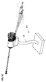
経尿道蒸気送出デバイス100が、組立てられた形態で図1Aに示され、図1Bは、分解図であり、蒸気送出デバイスの再使用可能なハンドル部分102と使い捨てカートリッジ部分104を示す。蒸気送出デバイスのハンドル部分102は、管腔103と、RF発生器(図示せず)にプラグ接続される電気ケーブル106と、グリップ部分107と、洗浄、ニードルの前進/後退、RF電力のON/OFFの作動ためのトリガ108と、管腔内に配置され且つ蒸気を誘導式に生成するように構成されたRFコイル110(図示せず)と、ハンドル部分内に配置され且つ蒸気ニードルを前進させたり後退させたりするように構成されたソレノイドコイル112(図示せず)を含む。
[Semi-disposable steam delivery device]
A transurethral
RF発生器は、蒸気を生成するための電力及び流体を経尿道蒸気送出デバイスに供給するように構成される。例えば、RF発生器は、RFエネルギをハンドル部分のRFコイルに供給するように構成される。RF発生器はまた、潅流/冷却流体、吸引等の作動のために不可欠な電力及び他の構成要素をシステムに供給するために蒸気送出デバイスに接続される。RF発生器は、蒸気治療中の作動パラメータ及び制御をユーザに提供するために、電子コントローラ及びグラフィカルユーザインタフェース(GUI)を含むのがよい。 The RF generator is configured to supply power and fluid to the transurethral steam delivery device for generating steam. For example, an RF generator is configured to supply RF energy to an RF coil on the handle portion. The RF generator is also connected to a vapor delivery device to supply the system with power and other components essential for operation of irrigation/cooling fluids, suction, etc. The RF generator may include an electronic controller and graphical user interface (GUI) to provide the user with operating parameters and control during vapor therapy.
RF発生器は、電気コネクタを含み、電気コネクタは、RF電流を蒸気送出デバイスに供給し、電気信号を蒸気送出デバイスのスイッチに送信し又はそれから受信し、測定値(例えば、蒸気送出デバイスの温度)及び電気信号を蒸気送出デバイスのコントローラ(例えば、その電気コネクタ)に送信し又はそれから受信して、測定値及び電気信号は、蒸気送出デバイスを識別したり、蒸気送出の履歴を追跡したり、所定の蒸気送出システムの過剰使用を防止するためのものである。RF発生器はまた、蒸気送出デバイスに食塩水等の冷却/潅流流体の流れを供給する蠕動ポンプを含むのがよい。 The RF generator includes an electrical connector that supplies RF current to the steam delivery device, transmits electrical signals to or receives electrical signals from switches in the steam delivery device, and provides measurements (e.g., temperature of the steam delivery device). ) and electrical signals are sent to or received from a controller (e.g., an electrical connector thereof) of the steam delivery device such that the measurements and electrical signals identify the steam delivery device, track steam delivery history, It is intended to prevent overuse of a given vapor delivery system. The RF generator may also include a peristaltic pump that supplies a flow of cooling/perfusing fluid, such as saline, to the vapor delivery device.
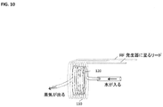
使い捨てカートリッジ104は、膀胱鏡及び蒸気送出ニードル116のための管腔を有する細長いシャフト114と、蒸気送出ニードルに取付けられ且つソレノイドコイル112内で発生させた磁場によって前進又は後退するたニードル駆動磁石118(図示せず)と、水が蒸気に誘導的に変換される蒸気コイル120と、滅菌水や食塩水による洗浄及び膀胱の排液のためのプラスチック管路122を含む。カートリッジ部分は、ハンドル部分102の管腔103に挿入されるように構成される。カートリッジ部分をハンドル部分に挿入するとき、カートリッジ104の蒸気コイル120を、ハンドル部分のRFコイル110内に整列させ且つ位置決めしてもよいし、変形例として(図10に示すように)、RFコイル110を蒸気コイル120の周りに整列させ且つ位置決めしてもよい。細長いシャフト114は、患者の尿道前立腺部及び前立腺まで延びることができる長さで患者の尿道に挿入されるように寸法決めされ且つ構成される。図1Bに示すように、カートリッジ104をハンドル内で回転させて、ハンドルを患者の脚の間で回転させることなしに、前立腺の左右の中葉への蒸気の送出を容易にしてもよい。
いくつかの手順において、蒸気治療は、経直腸的超音波(TRUS)撮像によって少なくとも部分的に案内される。これらの手順おいて、TRUSプローブは、蒸気送出デバイスハンドルが図1Aに示す垂直下方位置にあることを防止するのがよい。いくつかの変形実施形態では、送出デバイスハンドルは、送出デバイスのバレルから上方に延びていてもよい。他の実施形態では、バレルを、送出デバイストリガ及びケーブルを含むように修正して、ハンドル部分を全くなくしてもよい。 In some procedures, vapor therapy is guided at least in part by transrectal ultrasound (TRUS) imaging. During these procedures, the TRUS probe should prevent the vapor delivery device handle from being in the vertically downward position shown in FIG. 1A. In some alternate embodiments, the delivery device handle may extend upwardly from the barrel of the delivery device. In other embodiments, the barrel may be modified to include the delivery device trigger and cable and eliminate the handle portion altogether.
いくつかの手順において、送出デバイスニードルを前進させて、尿道壁の最初の孔あけ後、蒸気を2又は3以上の部位に送出する。ニードル進入孔の拡大による蒸気漏れを防止するために、蒸気送出ニードルが患者の解剖学的組織に対して安定したままであることが重要である。図1Cは、ニードル送出、前進、及び蒸気送出中、送出デバイスを安定化して保持するのに使用される調節可能な送出デバイスホルダ124を示している。この調節可能な送出デバイスホルダにより、オペレータは、画像案内されるニードルの配置及び治療の送出に集中することが可能である。図1Cは、可撓性で形状変更可能なシャフト126を有する調節可能な送出デバイスホルダを示し、かかるシャフト126は、治療中の送出デバイスニードルの位置を維持するようにオペレータによって調節される。他の実施形態では、保持デバイスは、電子的に調節されてもよい。保持デバイスは、送出デバイスを尿道から前進させたり後退させたりするように構成されてもよい。図1Cのハンドルは、図1Cに示す調節可能な保持デバイスと同じ程度に簡単であってもよいし、多軸ロボットアームと同じ程度に複雑であってもよい。
In some procedures, the delivery device needle is advanced to deliver steam to two or more sites after the initial piercing of the urethral wall. It is important that the steam delivery needle remain stable against the patient's anatomy to prevent steam leakage due to enlarged needle entry holes. FIG. 1C shows an adjustable
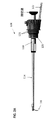
使い捨てカートリッジ104を図2A及び図2Bに断面図で示す。蒸気送出ニードル116は、ニードル駆動磁石118に剛性的に取付けられ、ニードル駆動磁石118は、ハンドル部分102(図3に図示)内のコイルによって発生させた磁場によって横方向に移動させられる。蒸気コイル120も、図2Bに示されている。使い捨てカートリッジは、抵抗温度計(RTD)119を含み、抵抗温度計(RTD)119は、リード123を介して導電金属リング121と直列に配線されている。抵抗温度計(RTD)119は、蒸気コイル120から出る蒸気の温度を測定することができる。一実施形態では、抵抗温度計(RTD)は、蒸気コイルの出口の周りに巻付けられるのがよい。
誘導式の読取りコイルを、再使用可能なハンドル内に設けるのがよい。熱電対を、再使用可能なハンドル部分のRFコイルの上に配置するのがよい。経験が示したことは、過熱(通常は煙)の徴候を示す第1の構成要素は、RFコイルであり、このことは、RFコイルがそれに隣接した内側コイルよりも幾分低い温度にあるときでもそうである。従って、RFコイルは、温度計、好ましくは熱電対のために好ましい場所である。 An inductive read coil may be provided within the reusable handle. A thermocouple may be placed over the RF coil of the reusable handle portion. Experience has shown that the first component to show signs of overheating (usually smoke) is the RF coil, and this occurs when the RF coil is at a somewhat lower temperature than the inner coil adjacent to it. But it is. An RF coil is therefore a preferred location for a thermometer, preferably a thermocouple.
使い捨てカートリッジ104を再使用可能なハンドル部分102に挿入するとき、カートリッジ104は、ハンドル内の斜めコイルと係合する。カートリッジの挿入及び引出し力は、全てのカートリッジが繰返し可能な機械力範囲内にあるように、厳格な範囲内に特定されるのがよい。斜めコイルは、摺動電気接点として機能し、摺動電気接点により、カートリッジからハンドルへのRTD出口温度計リードの電気的接触を維持しながら、ハンドル内でのカートリッジの回転を可能にする。カートリッジを回転させるとき、リングとコイルの間の接触抵抗のいくらかの変化がある。しかしながら、回転の間、正確な温度測定は必要ではなく、かくして、接触抵抗又は回転中の接触抵抗の任意の変化は、ソフトウエアでゼロにされるのがよい。出口温度計は、抵抗温度計(RTD)として示されているけれども、サーミスタ又は熱電対等の他の小型センサを採用してもよい。
When the
図2Bに示す蒸気コイルは、図1Aに示すように、カートリッジから延びるプラスチックチューブの中を通る滅菌水の供給部に接続され、且つ、RF発生器に接続される。蒸気コイルの複数の巻き部は、金属チューブ材で構成され、金属チューブ材は、例えば、18ゲージの普通の厚さ(RW)の304ステンレス鋼チューブ材、又は、18ゲージの薄厚(TW)のプラグ引きインコネル(登録商標)625チューブ材である。個々のコイル巻き部は、物理的に接触するのがよく、良好な電気接触を確保するために互いに半田付け又は溶接されるのがよいが、RF電流は、巻き部を分離する十分に薄い酸化層を通過する。 The steam coil shown in FIG. 2B is connected to a supply of sterile water through a plastic tube extending from the cartridge and to an RF generator as shown in FIG. 1A. The turns of the steam coil are constructed of metal tubing, such as 18 gauge regular thickness (RW) 304 stainless steel tubing or 18 gauge thin thickness (TW) tubing. Plugged Inconel® 625 tubing. The individual coil turns should be in physical contact and should be soldered or welded together to ensure good electrical contact, but the RF current should not be applied to a thin enough oxide to separate the turns. pass through the layers.
蒸気コイル120内の水は、蒸気コイルの周囲を流れる電流によって生じたオーム熱によって蒸気に変換される。これらの電流は、送出デバイスハンドル内に配置された同心のRFコイル内を流れるRF電流によって誘導される。RFコイル内の電流によって生じる交替磁場は、蒸気コイルを透磁性材料から製造することによって強化されるのがよい。300シリーズステンレス鋼の透磁率は冷間加工によって変化するので、同一の透磁率を有するチューブ材ロットを得ることは困難である。デバイスからデバイスへのカロリー出力の一貫性が非常に重要であるので、非磁性チューブ材が、この適用例に好ましい。304等のステンレス鋼を焼鈍して、磁気特性をなくしてもよいし、インコネル(登録商標)625、MP35N、エルジロイ等の非磁性鋼を蒸気コイル用に選択してもよい。インコネル(登録商標)625が望ましく、その理由は、その電気抵抗が、蒸気コイルの遠位(蒸気)端で経験することがある温度範囲(20℃~350℃)にわたって温度からほぼ独立であり、ショット毎の及びデバイス毎の一貫した蒸気の送出を可能にするからである。
Water in the
1又は2以上の電気リードが、無菌水ラインと一緒に、使い捨てカートリッジから延びる。ワイヤ又は電気リードは、RF発生器に接続され、カートリッジ識別及び使用データを供給する信号をカートリッジ内のEPROMから送信し又はそれから受信する。このケーブル内の他のワイヤは、信号をカートリッジ内の蒸気コイル上に位置する熱電対から他の診断データをカートリッジから供給することができる。別の実施形態では、EPROM線及び熱電対線は、使い捨てカートリッジ及びプラグから延び、非使い捨てハンドルに接続され、非使い捨てハンドルを通って主送出デバイスハンドルケーブルに至る小さいケーブルを含むことができる。変形例として、データは、以下に開示されているように、物理的リードの必要なくカートリッジから誘導結合することができる。 One or more electrical leads extend from the disposable cartridge along with a sterile water line. Wires or electrical leads are connected to an RF generator to transmit or receive signals from the EPROM in the cartridge that provide cartridge identification and usage data. Other wires in this cable can provide signals from thermocouples located on vapor coils in the cartridge and other diagnostic data from the cartridge. In another embodiment, the EPROM wire and thermocouple wire can include a small cable extending from the disposable cartridge and plug, connected to the non-disposable handle, through the non-disposable handle to the main delivery device handle cable. Alternatively, data can be inductively coupled from the cartridge without the need for physical leads, as disclosed below.
送出デバイスの再使用可能なハンドル部分102を、図3により詳細に示す。ソレノイドコイル112は、図2Bに示すニードル駆動磁石に対する押し/引き形態で構成される。完全に後退したニードル位置では、ニードル駆動磁石の近位端は、近位側/押し用ソレノイドコイル112と整列する。完全に延長されたニードル位置では、ニードル駆動磁石の遠位端は、遠位側/引き用ソレノイドコイル112と整列する。電流は、図5に示すように、押し用コイル及び引き用コイル内で反対方向に通される。押し用コイルは、反対極性ニードル駆動磁石に反発してそれをコイルの外に出す磁場を引き起こす。反発力のために、磁石は、押し用コイルの軸線に沿って安定した釣り合い状態にはなく、横方向に移動する傾向があり、ニードル駆動磁石とその周囲の間の接触及び軸線方向の前進に対する摩擦抵抗を増大させることがある。引き用コイルは、ニードル駆動磁石を引き用コイルに引きつける磁場を生成する。引き用コイルは、ニードル駆動磁石をコイルの軸線に引きつけ、それにより、押し用コイルの不安定性を除去する。押し用コイル及び引き用コイルの組合せは、単一コイルによって付与される力のほぼ2倍である。図5に見ることができるように、コイルの押し用/引き用の対はまた、コイル対への電流の方向を単に逆にすることにより、前進力と同一の後退力を形成する。
The
図3は、ソレノイドコイルに隣接した線形磁石位置センサ113の潜在的な位置を示している。線形磁石位置センサ113は、ニードル駆動磁石によって形成された磁場を検出するように構成される。比較的小さい磁場が、ソレノイドコイルによって発生される。2つのソレノイドコイルによって形成された磁場は、平均的に且つコイル間の中心平面において、互いに相殺される。線形磁石位置センサの電圧出力は、磁石(及び磁石に取付けられたニードル)の位置の線形関数である。1回の較正を実行することにより、センサ電圧を、センサの最近位位置に対する磁石位置に変換することができる。
FIG. 3 shows potential positions of the linear
図3に示すRFコイル110は、使い捨てカートリッジがハンドル部分102に挿入されたときに蒸気コイル(図2Bの蒸気コイル120)のできるだけ近くに配置されるように設計され、その結果、蒸気コイル内の電流の最大誘導が得られる。組立てられたデバイス内のRFコイルと蒸気コイルの関係を図10に示す。一実施形態では、蒸気コイルは、6巻きの#18 TWインコネル(登録商標)625チューブを含み、RFコイルは、#44銅製マグネット線の個々の撚糸で構成された11巻きの#22銅リッツ線を含む。これらの寸法は、425kHz~475kHzの範囲の作動周波数でRFコイルと蒸気コイルの間の電磁結合を最適化するように選択される。RFコイルのリッツ線上の絶縁は、ほぼ250℃の温度定格を有する0.002’’厚押し出しPFAとすることができる。
The
図4に示す特定の実施形態では、ニードル駆動磁石118は、等級N52のネオジム-鉄-ホウ素から製造され、15mmの外径寸法及び18mmの長さを有する。内側の切欠きは、ニードル取付け部に嵌合するように形状決めされる。この特定の向きの磁石材料の残留磁気誘導(残留磁束密度)Brは、約1.5テスラであるのがよい。
In the particular embodiment shown in FIG. 4,
再使用可能な送出デバイスハンドルの他の特徴は、ハンドル内のカートリッジの横移動を防止するロッキングラッチ、及びハンドル内のカートリッジの30度毎の回転を定める戻り止めを含む。 Other features of the reusable delivery device handle include locking latches that prevent lateral movement of the cartridge within the handle, and detents that define every 30 degree rotation of the cartridge within the handle.
〔増大されたニードル長さ及びパルス送出〕
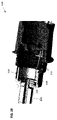
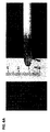
癌治療のための蒸気は、尿道内から前立腺の周囲中葉に到達する必要があるので、蒸気ニードルは、BPH手順の場合よりも更に蒸気送出ニードルから延びる必要がある。尿道壁を貫通した展開後の蒸気ニードルの位置、及び、ニードルが完全に延長された位置を図6A及び図6Bに示す。
[Increased Needle Length and Pulse Delivery]
Because the vapor for cancer therapy needs to reach the peri-middle lobe of the prostate from within the urethra, the vapor needle needs to extend further from the vapor delivery needle than in the BPH procedure. The position of the steam needle after deployment through the urethral wall and the fully extended position of the needle are shown in FIGS. 6A and 6B.
BPH用蒸気送出ニードル(図6A)の12mmまでの移動から癌用蒸気送出ニードルの24mmまでの移動への増大は、ニードル長さを増大させること、及び、図7に示すように、ソレノイドの2つのコイルの間の隙間幅を増大させることによって達成される。例えば、BPH用デバイスのソレノイドコイルの各々は、巻数408の#30マグネット線を含み、その結果、12mmまでのニードル移動が得られ、癌用デバイス内のソレノイドコイルの各々は、巻数605の#28マグネット線を含み、その結果、24mmまでのニードル移動が得られる。いくつかの実施形態では、ニードルは、前立腺被膜を突き通すことを回避するために、24mmを超えて延びることができない。しかしながら、摩擦を克服して尿道壁を孔あけするのに十分な力でニードルを展開するために必要とされる力は、BPH用システムの#30ゲージコイルで達成することができない。一実施形態では、この力は、ボビンをより多い巻数のより低いゲージの線で巻くことによって増大される。抵抗は、癌用コイル及びBPH用コイルに対して同じままであり、発生器24ボルト電源から送出された電流を最適化するように選択される。 Increasing the travel of the BPH vapor delivery needle (FIG. 6A) from 12 mm to 24 mm of the cancer vapor delivery needle increases the needle length and, as shown in FIG. This is achieved by increasing the gap width between the two coils. For example, each of the solenoid coils in the BPH device contains #30 magnet wire with 408 turns, resulting in up to 12 mm of needle travel, and each of the solenoid coils in the cancer device contains #28 with 605 turns. Includes magnet wire, resulting in needle travel of up to 24 mm. In some embodiments, the needle cannot extend beyond 24 mm to avoid penetrating the prostatic capsule. However, the force required to overcome friction and deploy the needle with sufficient force to perforate the urethral wall cannot be achieved with the #30 gauge coil of the system for BPH. In one embodiment, this force is increased by winding the bobbin with more turns of lower gauge wire. The resistance remains the same for the cancer coil and the BPH coil and is chosen to optimize the current delivered from the generator 24 volt power supply.
#28ゲージのワイヤの直径が#30ゲージのワイヤの直径よりも僅かに大きいので、より多くの巻数の#28ゲージのワイヤを配置するにはボビンの外径を増大させ且つボビン内壁の肉厚を低減させる必要がある。磁石位置に対して計算された力を図8に示し、展開及び後退の初期の力は、摩擦を克服するのに十分である2ポンド(約0.9キログラム)を超えている。ピークの力は、7.1ポンド(約3.2キログラム)であり、これは、ピークのBPHニードル力よりも大きい。より大きい力は、より多くの電流を送出することができる電源を使用することによって、及び、力を増大させるためにソレノイドコイルのワイヤゲージを最適化することによって達成される。ソレノイドに送出される電力(電圧×電流)は、100ワット~250ワットの範内にあり、電流は、10msec~250msec、好ましくは50msec~150msecの範囲の時間にわたってONであるのがよい。 Since the diameter of #28 gauge wire is slightly larger than the diameter of #30 gauge wire, to accommodate more turns of #28 gauge wire, the outer diameter of the bobbin must be increased and the inner wall thickness of the bobbin must be increased. need to be reduced. Forces calculated for the magnet positions are shown in FIG. 8 and the initial forces for deployment and retraction exceed 2 pounds, which is sufficient to overcome friction. The peak force is 7.1 pounds (approximately 3.2 kilograms), which is greater than the peak BPH needle force. Greater force is achieved by using a power supply capable of delivering more current and by optimizing the wire gauge of the solenoid coil to increase the force. The power (voltage x current) delivered to the solenoid should be in the range of 100 Watts to 250 Watts and the current should be ON for a time in the range of 10 msec to 250 msec, preferably 50 msec to 150 msec.
一実施形態では、同じ再使用可能なハンドル部分を使用して別々の使い捨てカートリッジ部分が、BPH及び前立腺癌の蒸気送出手順のために設けられてもよい。それぞれの使い捨てカートリッジ部分は、手順に応じて変化する蒸気送出ニードル長さを含む。変形実施形態では、図7におけるソレノイドコイル間の距離は、同じ使い捨てカートリッジ部分を使用しながらBPH及び癌の両方の手順に適切なニードル送出長さを選択するために、オペレータによって調節可能であるのがよい。 In one embodiment, separate disposable cartridge portions using the same reusable handle portion may be provided for BPH and prostate cancer vapor delivery procedures. Each disposable cartridge portion includes a vapor delivery needle length that varies with the procedure. In an alternative embodiment, the distance between the solenoid coils in FIG. 7 is adjustable by the operator to select appropriate needle delivery lengths for both BPH and cancer procedures while using the same disposable cartridge portion. is good.
上述したように、蒸気送出デバイスを、患者に経尿道的に挿入して、前立腺へのアクセスを得る。蒸気送出ニードルを、前立腺内の蒸気送出ニードルのリアルタイム超音波画像によって案内し、尿道の壁を横切る又は貫通するように展開し、前立腺内の最も遠位の位置まで前進させる。ニードルの前進中又はその後の後退中、蒸気を送出して治療を実施する。ユーザは、蒸気送出ニードルを、初期の展開において行われるような大きい距離にわたる非常に迅速な展開ではなく、小さい増分で前進させることを好むであろう。この目標を達成するために、ユーザがデバイスのハンドル部分のトリガを押込むのに応じて、電流のパルスをRF発生器からソレノイドコイルに送出する。磁気位置センサを使用して、磁石及び蒸気送出ニードルの移動を測定し、増分の寸法を制御することができる。好ましい実施形態では、電流の各パルスは、ニードルを1mmだけ展開し、トリガを押したときにパルスが送出される速度は、1秒当たり1~5パルスである。これらのパラメータは両方とも、ユーザが調節可能であるのがよい。 As described above, a vapor delivery device is inserted transurethrally into the patient to gain access to the prostate. A vapor delivery needle is guided by real-time ultrasound imaging of the vapor delivery needle within the prostate, deployed across or through the wall of the urethra, and advanced to the most distal position within the prostate. Steam is delivered during needle advancement or subsequent retraction to deliver treatment. Users may prefer to advance the vapor delivery needle in small increments rather than very rapid deployment over large distances as is done in initial deployment. To achieve this goal, a pulse of current is delivered from the RF generator to the solenoid coil in response to the user depressing the trigger on the handle portion of the device. A magnetic position sensor can be used to measure the movement of the magnet and vapor delivery needle to control the size of the increments. In a preferred embodiment, each pulse of current expands the needle by 1 mm and the rate at which the pulses are delivered when the trigger is pressed is 1-5 pulses per second. Both of these parameters should be user adjustable.
図6A及び図6Bに見ることができるように、蒸気送出ニードルの先端は、鈍いのがよく、これは、ニードル設計によって、又は、鋭い先端の材料の除去によって達成される。ニードルは、初期の展開中に尿道の壁を突き通すのに十分、鋭く設計され且つ力が大きくてもよいが、パルスによるニードル前進ステップにより前立腺被膜を貫通させることができないように十分に鈍い。前立腺被膜へのニードル先端のぶつかりは、超音波画像上での「テンティング(tenting)」としてユーザによって観察されるのがよい。ニードル位置センサが、パルスを適用した後に異常に小さいニードルの前進を記録したら、第2の指示がニードル位置センサによって供給されるのがよい。システムは、更なる前進ステップを取り止め、及び/又は、警告メッセージをユーザに提供するのがよい。 As can be seen in Figures 6A and 6B, the tip of the vapor delivery needle can be blunt, which is achieved by the needle design or by removal of sharp tip material. The needle may be designed sharp and forceful enough to penetrate the wall of the urethra during initial deployment, but blunt enough so that the pulsed needle advancement step cannot penetrate the prostatic capsule. Needle tip impingement on the prostatic capsule may be observed by the user as "tenting" on the ultrasound image. A second indication may be provided by the needle position sensor if the needle position sensor registers an abnormally small amount of needle advancement after applying the pulse. The system may cancel further forward steps and/or provide a warning message to the user.
いくつかの手順において、蒸気が尿道壁のニードル進入孔から漏れないようにすることが困難であることがある。孔あけ後の送出デバイス及びニードルの移動は、進入孔を拡大させ、蒸気漏れを容易にする。蒸気漏れを防止する技術を図9A及び図9Bに示す。この実施形態では、膨脹可能なバルーン材料130は、蒸気送出孔の近位側の距離4~24mmのところに且つ蒸気送出ニードル116の凹部に設けられる。蒸気ポート117を介する蒸気送出の間、蒸気は、ニードル壁の孔132を介してバルーン130にも入り、バルーンが膨らんで、ニードルに隣接した組織にぶつかり、蒸気が、突き通した部位から漏れて戻ることを阻止する。バルーン材料は、非準拠品であってもよく、製造において設定された直径まで膨脹するのがよい。非準拠バルーン材料は、PET(ポリエチレンテレフタレート)、ナイロン、又は非準拠医療バルーンに使用される他の材料から選択されるのがよい。バルーンの材料及び厚さは、蒸気と周囲組織との間の断熱をもたらすように選択されるのがよい。
In some procedures, it can be difficult to prevent vapor from escaping through the needle entry hole in the urethral wall. Movement of the delivery device and needle after piercing enlarges the entry hole and facilitates vapor leakage. A technique for preventing steam leakage is shown in FIGS. 9A and 9B. In this embodiment, an
蒸気送出孔の数及びそれらの直径は、特定の適用例に合せて選択されるのがよい。図9A及び図9Bは、2つの蒸気送出孔からなる列を3つ有するニードルを示している。孔長さが短いほど、蒸気送出が正確になり、これは、小さい周囲領域又は狭い領域の各部分を処置する場合に特に重要とすることができる。 The number of steam delivery holes and their diameter should be selected for a particular application. Figures 9A and 9B show a needle with three rows of two steam delivery holes. The shorter the pore length, the more precise the vapor delivery, which can be particularly important when treating portions of small peripheral or narrow areas.
〔治療のための送出の一貫性の改善〕
本発明の蒸気送出デバイスのカロリー出力は、効率係数を通じた治療送出中のRF発生器の電力入力に関連する。カロリー出力は、送出された電力がデバイスの熱サイクルに起因する成分値の変化とは独立の定数である場合、ショット毎に一貫し又は不変である。カロリー出力は、入力電力が所与の治療に対して常に同じである場合、及び、効率係数がデバイス毎に一貫している場合、デバイス毎に一貫し又は不変である。デバイス毎の一貫性又は不変性は、デバイス製造の一貫性により達成される。更に、一貫性は、入力電力が一定に保持されることを条件として、電力結合効率が100%に近づく時に改善する。換言すると、デバイスパラメータの変動は、出力に送出された一定の入力電力の割合が100%に近づく時に出力に与える影響は減少する。
[Improved Consistency of Delivery for Treatment]
The calorie output of the vapor delivery device of the present invention is related to the power input of the RF generator during therapy delivery through an efficiency factor. The caloric output is consistent or unchanged from shot to shot if the power delivered is a constant independent of changes in component values due to thermal cycling of the device. Caloric output is consistent or invariant from device to device if the input power is always the same for a given therapy and if the efficiency factor is consistent from device to device. Consistency or constancy from device to device is achieved through device manufacturing consistency. Furthermore, the consistency improves when the power coupling efficiency approaches 100%, provided that the input power is held constant. In other words, variations in device parameters have less effect on the output as the percentage of constant input power delivered to the output approaches 100%.
図10のRFコイル110及び蒸気コイル120は、効率的で一貫した治療送出の利点を有する。最初に、蒸気コイルの比較的少ない巻数(図10に示す6巻き)は、蒸気コイルの遠位端に発生した過剰な熱が、コイルに入る予熱室温水を予熱するために戻されて6つの巻き部の熱伝導金属を通過することができることを意味する。癌に対する蒸気コイルの出口温度は、一部の場合に熱的フィードバックに起因してデバイスからの所与のカロリー出力に対してBPHに対する蒸気コイルの出口温度よりも低いことが観察されている。更に、コイル間の分離の変化によって生じるRFコイルと蒸気コイルの間の変圧器結合係数の変化は、直径が大きいコイルほど小さい。
The
〔蒸気送出システムセンサ〕
蒸気コイルの出口での蒸気の温度及び蒸気コイルの温度は、システムコントローラによって連続的に測定及びモニタするのがよい。設定範囲外である温度は、蒸気コイルの損傷又は蒸気治療の不十分な送出を示す場合があり、自動停止及び是正処置に関するユーザへの案内の契機にするのがよい。例えば、温度過剰は、水ラインチューブ内のキンク又は閉塞を示す場合がある。温度不足は、RFコイルへのRF電力の損失を示す場合がある。説明するデバイスの半使い捨て設計は、使い捨てカートリッジ内の温度を測定し、送出デバイスハンドル内の無線読取り機構を通して通信される無線センサに送信する。無線手法により、ハンドル内の使い捨てカートリッジの自由回転が可能であり、これは、更なるコストを伴わない重要な臨床的特徴である。
[Steam delivery system sensor]
The temperature of the steam at the outlet of the steam coil and the temperature of the steam coil may be continuously measured and monitored by a system controller. A temperature that is out of the set range may indicate damaged steam coils or inadequate delivery of steam therapy, and may trigger automatic shutdown and guidance to the user regarding corrective action. For example, overtemperature may indicate a kink or blockage in the water line tubing. Undertemperature may indicate a loss of RF power to the RF coil. The semi-disposable design of the device described measures the temperature within the disposable cartridge and transmits it to a wireless sensor that is communicated through a wireless reader in the delivery device handle. The wireless approach allows free rotation of the disposable cartridge within the handle, an important clinical feature at no additional cost.
図11は、射出蒸気RTD(抵抗温度センサ)の温度読取りのための等価回路を示している。回路パラメータの適切な選択で、感知された電圧は、Rsenseの単調関数、すなわち、銅線RTDの抵抗であり、この単調関数は、銅線の温度係数を通じた温度の線形関数であることを示すことができる。感知された電圧Vsenseの関数として内側コイルの温度の式を示すためにVsenseの式を逆変換する。典型的には、発振器の単一周波数は、発生器周波数を含む処置室に存在する場合がある任意その他の周波数と異なるように選択される。他方、一実施形態では、図11の単一周波数発振器は、コストを軽減して構成要素の数を最小にするためにごく僅かなRF電源電圧として取ることができる。この場合に、治療中にRFコイルから任意の誘導ピックアップを管理するように注意しなければならない。 FIG. 11 shows an equivalent circuit for the temperature reading of the injected steam RTD (resistance temperature sensor). With proper choice of circuit parameters, the sensed voltage is a monotonic function of Rsense, the resistance of the copper wire RTD, which is shown to be a linear function of temperature through the temperature coefficient of the copper wire. be able to. Invert the Vsense equation to give an equation for the inner coil temperature as a function of the sensed voltage Vsense. Typically, the single frequency of the oscillator is chosen to be different from any other frequencies that may be present in the treatment room, including the generator frequency. On the other hand, in one embodiment, the single frequency oscillator of FIG. 11 can be taken as a negligible RF supply voltage to reduce cost and minimize component count. In this case, care must be taken to manage any inductive pickup from the RF coil during treatment.
図11の1kOhm抵抗器は、単一周波数発振器電圧を単一周波数電流源に変換する。発振器及び1kOhm抵抗器は、図11の単一周波数電流源が取って代わることができる。10mA~100mAの範囲の単一周波数電流により、Vsenseから計算されたVsense測定及び出口温度読取り値において優れたSN比が得られることになる。温度は、センサ巻き部の0.5’’の長さにわたる平均値である。この空間平均は、温度の変動を滑らかにし、温度の変動は、出口で蒸気の誤った挙動に起因して複数の点に発生する可能性がある。 The 1 kOhm resistor in FIG. 11 converts a single frequency oscillator voltage into a single frequency current source. The oscillator and 1 kOhm resistor can be replaced by the single frequency current source of FIG. A single frequency current in the range of 10 mA to 100 mA will give excellent signal-to-noise ratios in Vsense measurements and outlet temperature readings calculated from Vsense. Temperatures are averaged over the 0.5″ length of the sensor winding. This spatial averaging smooths out temperature fluctuations, which can occur at multiple points due to erroneous behavior of the steam at the exit.
無線読取り/書込みRFIDタグは市販されている。これらの一部は、温度測定を行うことができる。そのようなデバイスは、使い捨てカートリッジに追加される場合、経済的な価格である必要がある。別の実施形態では、使い捨てカートリッジのIDは、RF発生器によって読取られるが、RF発生器へのインターネット接続を通してeクラウドに書き込まれる。使用中の全ての発生器は、送出デバイスハンドルに挿入された使い捨てデバイスに対して使用情報を検索するために毎回の治療手順前にクラウドに接続することができる。治療の終わりに、そのデバイスによって送出された治療ショットの回数は、クラウドに中継されてクラウドに格納されることになる。 Wireless read/write RFID tags are commercially available. Some of these are capable of temperature measurements. Such a device should be economically priced when added to a disposable cartridge. In another embodiment, the ID of the disposable cartridge is read by the RF generator, but written to the e-cloud through an internet connection to the RF generator. All generators in use can connect to the cloud prior to every treatment procedure to retrieve usage information for disposable devices inserted into the delivery device handle. At the end of treatment, the number of treatment shots delivered by the device will be relayed to and stored in the cloud.
〔経尿道システムを使用する方法〕
図12は、周囲領域組織に隣接した尿道前立腺部に挿入された送出デバイスを示している。カテーテル配置は、超音波画像及び膀胱鏡カメラによって案内されるのがよく、更に、可視の目印である精丘の真後ろの周囲領域へのアクセスの位置によって案内されてもよい。最初、ニードルを、ニードル位置センサによって測定されるように、約11mmの移動距離にわたって前進させる。初期移動距離は、6~12mmの範囲であるのがよく、ニードルを尿道内層から周囲領域組織に展開しなければならない。
[Method using a transurethral system]
FIG. 12 shows the delivery device inserted into the prostatic urethra adjacent the surrounding area tissue. Catheter placement may be guided by ultrasound images and a cystoscopic camera, and may also be guided by the location of access to the peripheral region directly behind the verumontanum, which is a visible landmark. Initially, the needle is advanced over a travel distance of approximately 11 mm as measured by the needle position sensor. The initial travel distance may be in the range of 6-12 mm, and the needle should be deployed from the urethral lining to the surrounding area tissue.
展開トリガスイッチの更なる押込みにより、ソレノイドは、電流パルスを固定された又はユーザによって選択された速度で作動させ、かかる速度は、1~5パルス/秒の範囲であるのがよい。一実施形態では、電流パルスは、システム発生器が供給することができる最大振幅と、固定された又はユーザによって選択された初期パルス幅を有する。一実施形態では、初期パルス幅Tは、1.5msecである。パルスがソレノイドに送出されるとき、ニードル位置センサは、ニードル移動距離を測定し、ニードルがターゲット移動距離、例えば、1mmよりも移動していなかったならば、次のパルスの幅を増大させ、ニードルがターゲット移動距離よりも移動していたならば、次のパルスの幅を減少させる。平均すれば、ニードルは、各パルスにおいてターゲット移動距離だけ移動する。ターゲット移動距離は、固定されていてもよいし、ユーザによって選択されてもよく、好ましい実施形態では、1mmである。いかなる時においても、ユーザは、ニードルのパルスによる後退又は全後退を可能にするのがよい。いかなる時においても、例えば蒸気治療を送出するために、ユーザは、トリガを緩めて、ニードルのパルス前進/後退を停止させてもよい。ニードル位置センサの出力を表示して、ユーザが、ニードル先端と送出デバイスシャフトの間のニードルに沿う距離を知るのがよい。 Further depression of the deployment trigger switch causes the solenoid to actuate current pulses at a fixed or user-selected rate, which may range from 1 to 5 pulses/second. In one embodiment, the current pulse has a maximum amplitude that the system generator can provide and an initial pulse width that is fixed or selected by the user. In one embodiment, the initial pulse width T is 1.5 msec. When a pulse is delivered to the solenoid, the needle position sensor measures the needle travel distance and if the needle has not traveled more than the target travel distance, e.g. has moved more than the target distance, decrease the width of the next pulse. On average, the needle moves the target travel distance in each pulse. The target travel distance may be fixed or selected by the user, and in a preferred embodiment is 1 mm. At any time, the user should be able to pulse or fully retract the needle. At any time, for example, to deliver steam therapy, the user may release the trigger to stop the pulsed advancement/retraction of the needle. The output of the needle position sensor may be displayed so that the user knows the distance along the needle between the needle tip and the delivery device shaft.
パルス幅を制限する、従って、ニードルに付与される力を、前立腺被膜を突き通すことができない値まで制限する安全特徴を行うのがよい。ニードルが一連のNパルスに対して1mmのターゲット移動距離よりも移動していなかったならば、ニードル妨害状態が示され、ユーザに警告される。変形例として、ニードル妨害状態が示されたら、蒸気送出ニードルを更に前進させることを阻止するのがよい。ニードル妨害状態は、前立腺の外嚢にぶつかっているニードルによることがあり、Nの値は、パルス幅を組織調査において決定された安全最大値に制限するように選択され、安全な最大値に関して、ニードルは、健康な又は癌が発症した嚢を突き通すことができない。Nは、4~10パルスの範囲内であるのがよく、それに対応する最大パルス幅は、2~5msecの範囲内であるのがよい。ユーザは、ニードルが嚢にぶつかったことを、超音波画像上の組織テンティングを観察することによって確認するのがよい。 A safety feature that limits the pulse width and thus limits the force applied to the needle to a value that does not penetrate the prostatic capsule may be implemented. If the needle has not moved more than the target travel distance of 1 mm for a series of N pulses, a needle jam condition is indicated and the user is alerted. Alternatively, further advancement of the vapor delivery needle may be blocked if a needle blockage condition is indicated. A needle blockage condition may be due to the needle hitting the outer capsule of the prostate, and the value of N is selected to limit the pulse width to a safe maximum determined in tissue studies, with respect to the safe maximum: Needles cannot penetrate healthy or cancerous sacs. N should be in the range of 4-10 pulses and the corresponding maximum pulse width should be in the range of 2-5 msec. The user may confirm that the needle has hit the capsular bag by observing tissue tenting on the ultrasound image.
変形実施形態では、ユーザは、パルス幅及び1秒当たりのパルス数を直接制御するのがよい。この手動のニードル移動モードは、上述した自動モードの安全特徴を保つのがよい。 In alternate embodiments, the user may directly control the pulse width and number of pulses per second. This manual needle movement mode should retain the safety features of the automatic mode described above.
経尿道蒸気治療は、嚢外面上の神経を損傷するのに十分な高い温度を警告するために、前立腺被膜の外側に会陰を通して挿入された熱電対と共に使用してもよい。神経を冷却及び保護するために前立腺被膜の外側に食塩水を送出することができる。他方、経尿道前立腺切除治療は、複数のショットを使用して実施することができ、各ショットは、嚢を通って神経までの有意な熱伝導を防止するのに十分なショット間の時間を用いて十分なものである。例えば、ショット間の少なくとも30秒を用いて10秒又はそれ未満続く個々の治療により、嚢外側での熱電対又は食塩水注射ニードルの必要がなく前立腺組織の完全な焼灼を得ることができる。 Transurethral steam therapy may be used with thermocouples inserted through the perineum outside the prostate capsule to warn of temperatures high enough to damage nerves on the extracapsular surface. Saline can be delivered outside the prostate capsule to cool and protect the nerves. On the other hand, transurethral prostatectomy treatment can be performed using multiple shots, each with a time between shots sufficient to prevent significant heat conduction through the capsule to the nerve. is sufficient. For example, individual treatments lasting 10 seconds or less with at least 30 seconds between shots can obtain complete ablation of prostate tissue without the need for extracapsular thermocouples or saline injection needles.
いくつかの実施形態では、周囲領域及び移行領域は、別々に処置することができる。他の実施形態では、蒸気送出ニードルは、移行領域を通過した後に癌周囲領域組織に到達するのに十分に長い。治療は、パルス展開又はパルス後退中に周囲領域組織及び移行領域組織の両方に実施することができる。他の実施形態では、尿道に当たっている中心領域組織を癌治療処置中に焼灼してもよい。中心領域は、個別に又は一部の場合に移行領域への通過後に処置することができる。中心領域及び移行領域組織は、いずれも、1回のニードル展開又は後退中に処置することができる。 In some embodiments, the perimeter and transition areas can be treated separately. In other embodiments, the vapor delivery needle is long enough to reach the peritumortic tissue after passing through the transition region. Treatment can be applied to both surrounding and transition zone tissue during pulse deployment or pulse retraction. In other embodiments, the central region tissue impinging the urethra may be ablated during the cancer treatment procedure. The central region can be treated separately or in some cases after passing through the transition region. Both the central region and transition region tissue can be treated during a single needle deployment or retraction.
いくつかの実施形態では、超音波画像は、前立腺組織への蒸気の送出を案内するのに使用される。更に、ニードル位置センサによるニードル位置の測定は、サブmm精度を有し、治療ショット間の距離を測定するのに使用することができる。前立腺被膜にわたる過大な加熱及び潜在的な導通を防止するために、重なり合う障害をもたらすことになる距離による蒸気の送出をショット間の十分な分離で離間させることが重要である。いくつかの実施形態処置において、ショットは、1cmのショット間の分離を使用して実施される。 In some embodiments, ultrasound images are used to guide the delivery of vapor to prostate tissue. Additionally, the needle position measurement by the needle position sensor has sub-mm accuracy and can be used to measure the distance between treatment shots. To prevent excessive heating and potential conduction across the prostate capsule, it is important to space vapor delivery by a distance that would result in overlapping obstructions with sufficient separation between shots. In some embodiment procedures, shots are performed using a 1 cm shot-to-shot separation.
仮特許出願720に開示された治療方法及び手段は、経尿道処置に使用することができる。例えば、組織キャパシタンスを感知するセンサをニードル先端に追加することにより、前立腺組織と非前立腺組織とを区別することができ、非前立腺組織への蒸気送出を防止して前立腺被膜の不意の通過を防止することができる。組織タイプの感知をニードル/磁石位置センサと共に使用して磁石が前立腺組織内にあることを確認し、特に、いつニードルが前立腺被膜に隣接しているかを決定することができる。手術前画像を使用して、尿道に沿った最適穿刺部位及び各穿刺部位に送出する必要がある蒸気治療ショットの回数を決定することができる。その後に、治療ショット間の規定の距離により、経尿道前立腺切除処置を外部画像誘導なしに実行することができる。送出デバイスプローブは、BPH手順の場合と同様に、膀胱鏡画像内の解剖学的目印を識別することによって尿道内の規定の位置まで前進される。ニードルは、磁石/ニードル位置センサ出力によって及び/又は膀胱鏡越しに見えるニードル上のマーク付けによって案内されながら尿道壁を通って規定の距離に対して前進される。治療は、ニードル前進中に実施することができ、又はニードルはセンサによって表示される時に前立腺被膜壁に前進させることができ、治療は、後退中に実施することができる。 The treatment methods and means disclosed in provisional patent application '720 can be used for transurethral procedures. For example, by adding a sensor to the needle tip that senses tissue capacitance, it is possible to distinguish between prostatic and non-prostatic tissue, preventing vapor delivery to the non-prostatic tissue and preventing inadvertent passage through the prostatic capsule. can do. Tissue type sensing can be used with the needle/magnet position sensor to confirm that the magnet is within the prostate tissue and, in particular, to determine when the needle is adjacent to the prostatic capsule. Pre-operative images can be used to determine the optimal puncture sites along the urethra and the number of vapor therapy shots that should be delivered to each puncture site. Thereafter, the prescribed distance between treatment shots allows the transurethral prostatectomy procedure to be performed without external image guidance. The delivery device probe is advanced to a defined position within the urethra by identifying anatomical landmarks in the cystoscopic image, as in the BPH procedure. The needle is advanced for a defined distance through the urethral wall guided by the magnet/needle position sensor output and/or by markings on the needle visible through the cystoscope. Treatment can be performed during needle advancement, or the needle can be advanced to the prostatic capsular wall as indicated by a sensor and treatment can be performed during retraction.
別の例では、ニードル先端に又はその近くに配置された電磁センサ又は送信器は、先端の位置を前立腺の手術前又は実時間画像に対して追跡することを容易にすることができる。超音波の場合に、第2のセンサ又は送信器は、超音波振動子に隣接して配置することができるので、ニードル先端の位置及び向きが変換器に対して見出され、オートフォーカス及び画像強調が容易である。ニードル先端の追跡により、ロボット誘導又はニードルのナビゲーションを可能にすることができる。高度蒸気治療送出システムでは、ニードルをオペレータによって選択された画像上の点までロボット工学的に前進させ、規定の蒸気投与量をその部位で送出することができる。送出デバイスニードルの先端は、他のカテーテルシステムに使用される時にプルワイヤを使用してステアリング可能にすることができる。ステアリングを伴う画像誘導により、治療は、3次元パターンで最適に分離された位置を使用して実施することができる。例えば、磁石ニードル先端に取付けて大きい外部磁石を使用して先端をステアリングすることにより、より特殊なステアリング手段を使用することができる。 In another example, an electromagnetic sensor or transmitter placed at or near the needle tip can facilitate tracking the position of the tip relative to preoperative or real-time images of the prostate. In the case of ultrasound, a second sensor or transmitter can be placed adjacent to the ultrasound transducer so that the position and orientation of the needle tip can be found relative to the transducer for autofocus and imaging. Easy to emphasize. Needle tip tracking can enable robotic guidance or needle navigation. In advanced vapor therapy delivery systems, a needle can be robotically advanced to an operator-selected point on the image to deliver a prescribed dose of vapor at that site. The tip of the delivery device needle can be made steerable using a pull wire when used with other catheter systems. Image guidance with steering allows treatment to be delivered using optimally separated locations in a three-dimensional pattern. More specialized steering means can be used, for example by using a large external magnet attached to the magnet needle tip to steer the tip.
本発明の特定の実施形態を詳細に上述したが、この説明は単に例示を目的としており、本発明の以上の説明は包括的ではないことは理解されるであろう。本発明の特定の特徴は、一部の図面に示されているが、他の図面では示されておらず、これは便宜的なものであり、いずれの特徴も本発明により別の特徴と組み合わせることができる。いくつかの変形及び代替は当業者に明らかであろう。そのような代替及び変形は、特許請求の範囲に含まれることを意図している。従属請求項に示される特定の特徴は、組み合わせて本発明の範囲に入れることができる。本発明はまた、従属請求項が他の独立請求項を参照して複数の従属請求項フォーマットでこれに代えて書かれたかのような実施形態を包含する。 Although specific embodiments of the invention have been described above in detail, it will be understood that this description is for the purpose of illustration only and that the above description of the invention is not exhaustive. Certain features of the invention are shown in some drawings and not in others, and this is for convenience and any feature may be combined with another in accordance with the invention. be able to. Some modifications and alternatives will be apparent to those skilled in the art. Such alternatives and modifications are intended to be included within the scope of the claims. The specific features indicated in the dependent claims may be combined within the scope of the invention. The invention also encompasses embodiments in which dependent claims are alternatively written in multiple dependent claim format with reference to other independent claims.
Claims (19)
ハンドル部分と、
カートリッジ部分と、を有し、
前記ハンドル部分は、管腔と、前記管腔内に配置され且つRFエネルギの供給源に接続可能であるRFコイルを有し、
前記カートリッジ部分は、前記ハンドル部分の管腔に挿入されるように構成され、
前記カートリッジ部分は、患者の尿道に挿入されるように構成されたシャフトと、前記シャフト内に配置された蒸気送出ニードルと、前記蒸気送出ニードル及び流体源に流体接続された蒸気コイルと、第1のソレノイドコイル及び第2のソレノイドコイルと、前記蒸気送出ニードルの近位部分に取付けられたニードル駆動磁石を含み、
前記ハンドル部分内への前記カートリッジ部分の挿入により、前記蒸気コイルを前記RFコイル内に整列させ且つ位置決めし、
前記ニードル駆動磁石は、前記蒸気送出ニードルが後退位置にあるとき、前記第1のソレノイドコイル内に摺動可能に配置され、前記蒸気送出ニードルが延長位置にあるとき、前記第2のソレノイドコイル内に摺動可能に配置される、蒸気送出デバイス。 A vapor delivery device comprising:
a handle and
a cartridge portion;
the handle portion has a lumen and an RF coil disposed within the lumen and connectable to a source of RF energy;
the cartridge portion is configured to be inserted into a lumen of the handle portion;
The cartridge portion includes a shaft configured to be inserted into a patient's urethra, a vapor delivery needle disposed within the shaft , a vapor coil fluidly connected to the vapor delivery needle and a fluid source, and a first and a second solenoid coil, and a needle drive magnet attached to a proximal portion of said vapor delivery needle ;
aligning and positioning the vapor coil within the RF coil by insertion of the cartridge portion into the handle portion;
The needle drive magnet is slidably disposed within the first solenoid coil when the vapor delivery needle is in the retracted position and within the second solenoid coil when the vapor delivery needle is in the extended position. A vapor delivery device slidably disposed in the .
Priority Applications (2)
| Application Number | Priority Date | Filing Date | Title |
|---|---|---|---|
| JP2022132689A JP7366211B2 (en) | 2016-12-21 | 2022-08-23 | Steam ablation system and method |
| JP2023175445A JP2023171536A (en) | 2016-12-21 | 2023-10-10 | Vapor ablation systems and methods |
Applications Claiming Priority (5)
| Application Number | Priority Date | Filing Date | Title |
|---|---|---|---|
| US201662437617P | 2016-12-21 | 2016-12-21 | |
| US62/437,617 | 2016-12-21 | ||
| US201762538517P | 2017-07-28 | 2017-07-28 | |
| US62/538,517 | 2017-07-28 | ||
| PCT/US2017/067956 WO2018119269A1 (en) | 2016-12-21 | 2017-12-21 | Vapor ablation systems and methods |
Related Child Applications (1)
| Application Number | Title | Priority Date | Filing Date |
|---|---|---|---|
| JP2022132689A Division JP7366211B2 (en) | 2016-12-21 | 2022-08-23 | Steam ablation system and method |
Publications (3)
| Publication Number | Publication Date |
|---|---|
| JP2020501746A JP2020501746A (en) | 2020-01-23 |
| JP2020501746A5 JP2020501746A5 (en) | 2021-01-28 |
| JP7129980B2 true JP7129980B2 (en) | 2022-09-02 |
Family
ID=62557076
Family Applications (3)
| Application Number | Title | Priority Date | Filing Date |
|---|---|---|---|
| JP2019533193A Active JP7129980B2 (en) | 2016-12-21 | 2017-12-21 | Steam cautery system and method |
| JP2022132689A Active JP7366211B2 (en) | 2016-12-21 | 2022-08-23 | Steam ablation system and method |
| JP2023175445A Pending JP2023171536A (en) | 2016-12-21 | 2023-10-10 | Vapor ablation systems and methods |
Family Applications After (2)
| Application Number | Title | Priority Date | Filing Date |
|---|---|---|---|
| JP2022132689A Active JP7366211B2 (en) | 2016-12-21 | 2022-08-23 | Steam ablation system and method |
| JP2023175445A Pending JP2023171536A (en) | 2016-12-21 | 2023-10-10 | Vapor ablation systems and methods |
Country Status (6)
| Country | Link |
|---|---|
| US (2) | US11246640B2 (en) |
| EP (1) | EP3558139A4 (en) |
| JP (3) | JP7129980B2 (en) |
| CN (2) | CN115500931A (en) |
| AU (2) | AU2017382873B2 (en) |
| WO (1) | WO2018119269A1 (en) |
Cited By (1)
| Publication number | Priority date | Publication date | Assignee | Title |
|---|---|---|---|---|
| JP2022162036A (en) * | 2016-12-21 | 2022-10-21 | ボストン サイエンティフィック サイムド,インコーポレイテッド | Vapor ablation systems and methods |
Families Citing this family (9)
| Publication number | Priority date | Publication date | Assignee | Title |
|---|---|---|---|---|
| US9833277B2 (en) | 2009-04-27 | 2017-12-05 | Nxthera, Inc. | Systems and methods for prostate treatment |
| EP3079617B1 (en) | 2013-12-10 | 2018-09-26 | Nxthera, Inc. | Vapor ablation systems |
| CA3068011A1 (en) | 2017-06-20 | 2018-12-27 | Aegea Medical Inc. | Induction coil assembly for uterine ablation and method |
| JP2023508613A (en) * | 2019-12-30 | 2023-03-02 | フランシス メディカル, インク. | Steam therapy system and method |
| BR112023018616A2 (en) * | 2021-03-16 | 2023-10-24 | Francis Medical Inc | STEAM THERAPY SYSTEMS AND METHODS |
| CA3220636A1 (en) * | 2021-06-10 | 2022-12-15 | Boston Scientific Scimed, Inc. | Medical device with distal articulable section |
| CN115031219A (en) * | 2022-08-10 | 2022-09-09 | 浙江伽奈维医疗科技有限公司 | Steam generation mechanism of steam ablation device and pistol |
| CN115005967A (en) * | 2022-08-10 | 2022-09-06 | 浙江伽奈维医疗科技有限公司 | Steam ablation gun, steam ablation equipment and control method |
| WO2024055914A1 (en) * | 2022-09-15 | 2024-03-21 | 苏州恒瑞宏远医疗科技有限公司 | Ablation needle driving system, pressure relief anti-scalding pipe, steam ablation system, and control method |
Citations (4)
| Publication number | Priority date | Publication date | Assignee | Title |
|---|---|---|---|---|
| JP2002035004A (en) | 2000-07-24 | 2002-02-05 | Olympus Optical Co Ltd | Therapeutic device for heating prostate |
| US20140276713A1 (en) | 2013-03-15 | 2014-09-18 | Tsunami Medtech, Llc | Medical system and method of use |
| US20160354140A1 (en) | 2008-10-06 | 2016-12-08 | Virender K. Sharma | Induction-Based Micro-Volume Heating System |
| US20180360523A1 (en) | 2015-12-18 | 2018-12-20 | Nxthera, Inc. | Vapor ablation systems and methods |
Family Cites Families (280)
| Publication number | Priority date | Publication date | Assignee | Title |
|---|---|---|---|---|
| US408899A (en) | 1889-08-13 | Island | ||
| US1719750A (en) | 1927-09-29 | 1929-07-02 | Charles E Parkhurst | Dental apparatus |
| US5542915A (en) | 1992-08-12 | 1996-08-06 | Vidamed, Inc. | Thermal mapping catheter with ultrasound probe |
| US5421819A (en) | 1992-08-12 | 1995-06-06 | Vidamed, Inc. | Medical probe device |
| US5435805A (en) | 1992-08-12 | 1995-07-25 | Vidamed, Inc. | Medical probe device with optical viewing capability |
| US5385544A (en) | 1992-08-12 | 1995-01-31 | Vidamed, Inc. | BPH ablation method and apparatus |
| US5370675A (en) | 1992-08-12 | 1994-12-06 | Vidamed, Inc. | Medical probe device and method |
| US4672963A (en) | 1985-06-07 | 1987-06-16 | Israel Barken | Apparatus and method for computer controlled laser surgery |
| JPH01139081A (en) | 1987-11-27 | 1989-05-31 | Olympus Optical Co Ltd | Apparatus for radiating laser beam |
| US4920982A (en) | 1988-06-27 | 1990-05-01 | Vastech Medical Products Inc. | Percutaneous vasectomy method |
| US5249585A (en) | 1988-07-28 | 1993-10-05 | Bsd Medical Corporation | Urethral inserted applicator for prostate hyperthermia |
| US5117482A (en) | 1990-01-16 | 1992-05-26 | Automated Dynamics Corporation | Porous ceramic body electrical resistance fluid heater |
| CN2061443U (en) | 1990-02-24 | 1990-09-05 | 山东省泰安市中心医院 | Pummp-type surgical cutting instrument using physiological saline |
| CA2048120A1 (en) | 1990-08-06 | 1992-02-07 | William J. Drasler | Thrombectomy method and device |
| DE69111079T2 (en) | 1990-12-10 | 1995-11-02 | Howmedica | Device for the interstitial application of laser light. |
| US5409453A (en) | 1992-08-12 | 1995-04-25 | Vidamed, Inc. | Steerable medical probe with stylets |
| US6461296B1 (en) | 1998-06-26 | 2002-10-08 | 2000 Injectx, Inc. | Method and apparatus for delivery of genes, enzymes and biological agents to tissue cells |
| US6231591B1 (en) | 1991-10-18 | 2001-05-15 | 2000 Injectx, Inc. | Method of localized fluid therapy |
| US7549424B2 (en) | 1991-10-18 | 2009-06-23 | Pro Surg, Inc. | Method and apparatus for tissue treatment with laser and electromagnetic radiation |
| US7429262B2 (en) | 1992-01-07 | 2008-09-30 | Arthrocare Corporation | Apparatus and methods for electrosurgical ablation and resection of target tissue |
| US6974453B2 (en) | 1993-05-10 | 2005-12-13 | Arthrocare Corporation | Dual mode electrosurgical clamping probe and related methods |
| US5902272A (en) | 1992-01-07 | 1999-05-11 | Arthrocare Corporation | Planar ablation probe and method for electrosurgical cutting and ablation |
| MX9300607A (en) | 1992-02-06 | 1993-10-01 | American Med Syst | APPARATUS AND METHOD FOR INTERSTITIAL TREATMENT. |
| US5330518A (en) | 1992-03-06 | 1994-07-19 | Urologix, Inc. | Method for treating interstitial tissue associated with microwave thermal therapy |
| US5300099A (en) | 1992-03-06 | 1994-04-05 | Urologix, Inc. | Gamma matched, helical dipole microwave antenna |
| US5370677A (en) | 1992-03-06 | 1994-12-06 | Urologix, Inc. | Gamma matched, helical dipole microwave antenna with tubular-shaped capacitor |
| US5413588A (en) | 1992-03-06 | 1995-05-09 | Urologix, Inc. | Device and method for asymmetrical thermal therapy with helical dipole microwave antenna |
| US5222185A (en) | 1992-03-26 | 1993-06-22 | Mccord Jr Harry C | Portable water heater utilizing combined fluid-in-circuit and induction heating effects |
| US5484400A (en) | 1992-08-12 | 1996-01-16 | Vidamed, Inc. | Dual channel RF delivery system |
| US5470308A (en) | 1992-08-12 | 1995-11-28 | Vidamed, Inc. | Medical probe with biopsy stylet |
| US5720718A (en) | 1992-08-12 | 1998-02-24 | Vidamed, Inc. | Medical probe apparatus with enhanced RF, resistance heating, and microwave ablation capabilities |
| US5556377A (en) | 1992-08-12 | 1996-09-17 | Vidamed, Inc. | Medical probe apparatus with laser and/or microwave monolithic integrated circuit probe |
| US5542916A (en) | 1992-08-12 | 1996-08-06 | Vidamed, Inc. | Dual-channel RF power delivery system |
| US5667488A (en) | 1992-08-12 | 1997-09-16 | Vidamed, Inc. | Transurethral needle ablation device and method for the treatment of the prostate |
| US5672153A (en) | 1992-08-12 | 1997-09-30 | Vidamed, Inc. | Medical probe device and method |
| US5720719A (en) | 1992-08-12 | 1998-02-24 | Vidamed, Inc. | Ablative catheter with conformable body |
| US5630794A (en) | 1992-08-12 | 1997-05-20 | Vidamed, Inc. | Catheter tip and method of manufacturing |
| AU5008293A (en) | 1992-08-17 | 1994-03-15 | Thomas L. Mehl | Hand-held, multi-purpose portable steamer |
| US5312399A (en) | 1992-09-29 | 1994-05-17 | Hakky Said I | Laser resectoscope with mechanical cutting means and laser coagulating means |
| DE4235506A1 (en) | 1992-10-21 | 1994-04-28 | Bavaria Med Tech | Drug injection catheter |
| AU685086B2 (en) | 1993-02-02 | 1998-01-15 | Vidamed, Inc. | Transurethral needle ablation device |
| CA2164860C (en) | 1993-06-10 | 2005-09-06 | Mir A. Imran | Transurethral radio frequency ablation apparatus |
| US5464437A (en) | 1993-07-08 | 1995-11-07 | Urologix, Inc. | Benign prostatic hyperplasia treatment catheter with urethral cooling |
| US5709680A (en) | 1993-07-22 | 1998-01-20 | Ethicon Endo-Surgery, Inc. | Electrosurgical hemostatic device |
| US5807395A (en) | 1993-08-27 | 1998-09-15 | Medtronic, Inc. | Method and apparatus for RF ablation and hyperthermia |
| DE4496959T1 (en) | 1993-09-14 | 1996-09-26 | Microsurge Inc | Endoscopic surgical instrument with guided jaws or jaws and locking control |
| US5797903A (en) | 1996-04-12 | 1998-08-25 | Ep Technologies, Inc. | Tissue heating and ablation systems and methods using porous electrode structures with electrically conductive surfaces |
| US5545171A (en) | 1994-09-22 | 1996-08-13 | Vidamed, Inc. | Anastomosis catheter |
| US5601591A (en) | 1994-09-23 | 1997-02-11 | Vidamed, Inc. | Stent for use in prostatic urethra, apparatus and placement device for same and method |
| US5558673A (en) | 1994-09-30 | 1996-09-24 | Vidamed, Inc. | Medical probe device and method having a flexible resilient tape stylet |
| US5531763A (en) | 1994-10-07 | 1996-07-02 | United States Surgical Corporation | Suture cinching apparatus |
| US5588960A (en) | 1994-12-01 | 1996-12-31 | Vidamed, Inc. | Transurethral needle delivery device with cystoscope and method for treatment of urinary incontinence |
| US6544211B1 (en) | 1995-02-06 | 2003-04-08 | Mark S. Andrew | Tissue liquefaction and aspiration |
| US6409722B1 (en) | 1998-07-07 | 2002-06-25 | Medtronic, Inc. | Apparatus and method for creating, maintaining, and controlling a virtual electrode used for the ablation of tissue |
| US6063081A (en) | 1995-02-22 | 2000-05-16 | Medtronic, Inc. | Fluid-assisted electrocautery device |
| US5897553A (en) | 1995-11-02 | 1999-04-27 | Medtronic, Inc. | Ball point fluid-assisted electrocautery device |
| JPH08264272A (en) | 1995-03-27 | 1996-10-11 | Seta Giken:Kk | Electromagnetic induction heater |
| US5645528A (en) | 1995-06-06 | 1997-07-08 | Urologix, Inc. | Unitary tip and balloon for transurethral catheter |
| US5628770A (en) | 1995-06-06 | 1997-05-13 | Urologix, Inc. | Devices for transurethral thermal therapy |
| US6238391B1 (en) | 1995-06-07 | 2001-05-29 | Arthrocare Corporation | Systems for tissue resection, ablation and aspiration |
| US5849011A (en) | 1995-06-19 | 1998-12-15 | Vidamed, Inc. | Medical device with trigger actuation assembly |
| US6607529B1 (en) | 1995-06-19 | 2003-08-19 | Medtronic Vidamed, Inc. | Electrosurgical device |
| US5843144A (en) | 1995-06-26 | 1998-12-01 | Urologix, Inc. | Method for treating benign prostatic hyperplasia with thermal therapy |
| US6036713A (en) | 1996-01-24 | 2000-03-14 | Archimedes Surgical, Inc. | Instruments and methods for minimally invasive vascular procedures |
| GB9605206D0 (en) * | 1996-03-12 | 1996-05-15 | Boc Group Plc | Medical devices |
| US5938692A (en) | 1996-03-26 | 1999-08-17 | Urologix, Inc. | Voltage controlled variable tuning antenna |
| US5830179A (en) | 1996-04-09 | 1998-11-03 | Endocare, Inc. | Urological stent therapy system and method |
| US5733319A (en) | 1996-04-25 | 1998-03-31 | Urologix, Inc. | Liquid coolant supply system |
| US5987360A (en) | 1996-05-03 | 1999-11-16 | Urologix, Inc. | Axial preferential thermal therapy |
| US6077257A (en) | 1996-05-06 | 2000-06-20 | Vidacare, Inc. | Ablation of rectal and other internal body structures |
| US5861021A (en) | 1996-06-17 | 1999-01-19 | Urologix Inc | Microwave thermal therapy of cardiac tissue |
| US5776176A (en) | 1996-06-17 | 1998-07-07 | Urologix Inc. | Microwave antenna for arterial for arterial microwave applicator |
| US5800486A (en) | 1996-06-17 | 1998-09-01 | Urologix, Inc. | Device for transurethral thermal therapy with cooling balloon |
| US6565561B1 (en) | 1996-06-20 | 2003-05-20 | Cyrus Medical Limited | Electrosurgical instrument |
| GB2314274A (en) | 1996-06-20 | 1997-12-24 | Gyrus Medical Ltd | Electrode construction for an electrosurgical instrument |
| US5976123A (en) | 1996-07-30 | 1999-11-02 | Laser Aesthetics, Inc. | Heart stabilization |
| US5792070A (en) | 1996-08-30 | 1998-08-11 | Urologix, Inc. | Rectal thermosensing unit |
| US6017361A (en) | 1997-03-13 | 2000-01-25 | Endo Care, Inc. | Urethral warming catheter |
| US5964756A (en) * | 1997-04-11 | 1999-10-12 | Vidamed, Inc. | Transurethral needle ablation device with replaceable stylet cartridge |
| US5873877A (en) | 1997-04-11 | 1999-02-23 | Vidamed, Inc. | Medical probe device with transparent distal extremity |
| US5871481A (en) | 1997-04-11 | 1999-02-16 | Vidamed, Inc. | Tissue ablation apparatus and method |
| US6017358A (en) | 1997-05-01 | 2000-01-25 | Inbae Yoon | Surgical instrument with multiple rotatably mounted offset end effectors |
| US6223085B1 (en) | 1997-05-06 | 2001-04-24 | Urologix, Inc. | Device and method for preventing restenosis |
| US6009351A (en) | 1997-07-14 | 1999-12-28 | Urologix, Inc. | System and method for transurethral heating with rectal cooling |
| US6123083A (en) | 1997-08-29 | 2000-09-26 | Urologix, Inc. | Device and method for treatment of a prostate while preventing urethral constriction due to collagen rich tissue shrinkage |
| US6238389B1 (en) | 1997-09-30 | 2001-05-29 | Boston Scientific Corporation | Deflectable interstitial ablation device |
| US5964752A (en) | 1998-02-02 | 1999-10-12 | Stone; Kevin R. | Articular cartilage surface shaping apparatus and method |
| US6517534B1 (en) | 1998-02-11 | 2003-02-11 | Cosman Company, Inc. | Peri-urethral ablation |
| US6440127B2 (en) | 1998-02-11 | 2002-08-27 | Cosman Company, Inc. | Method for performing intraurethral radio-frequency urethral enlargement |
| US6258087B1 (en) | 1998-02-19 | 2001-07-10 | Curon Medical, Inc. | Expandable electrode assemblies for forming lesions to treat dysfunction in sphincters and adjoining tissue regions |
| US6147336A (en) | 1998-02-26 | 2000-11-14 | Japanese Research And Development Association For Application Of Electronic Technology In Food Industry | Induction heaters for heating food, fluids or the like |
| US6036631A (en) | 1998-03-09 | 2000-03-14 | Urologix, Inc. | Device and method for intracavitary cancer treatment |
| US6669694B2 (en) | 2000-09-05 | 2003-12-30 | John H. Shadduck | Medical instruments and techniques for highly-localized thermally-mediated therapies |
| US6210404B1 (en) | 1998-10-28 | 2001-04-03 | John H. Shadduck | Microjoule electrical discharge catheter for thrombolysis in stroke patients |
| US7674259B2 (en) | 2000-12-09 | 2010-03-09 | Tsunami Medtech | Medical instruments and techniques for thermally-mediated therapies |
| US7892229B2 (en) | 2003-01-18 | 2011-02-22 | Tsunami Medtech, Llc | Medical instruments and techniques for treating pulmonary disorders |
| US8016823B2 (en) | 2003-01-18 | 2011-09-13 | Tsunami Medtech, Llc | Medical instrument and method of use |
| US6508816B2 (en) | 1998-03-27 | 2003-01-21 | John H. Shadduck | Medical instrument working end creating very high pressure gradients |
| US6911028B2 (en) | 1998-10-28 | 2005-06-28 | John H. Shadduck | Medical instrument working end and method for endoluminal treatments |
| US6053909A (en) | 1998-03-27 | 2000-04-25 | Shadduck; John H. | Ionothermal delivery system and technique for medical procedures |
| JP2000005191A (en) | 1998-06-25 | 2000-01-11 | Olympus Optical Co Ltd | High-frequency therapeutic device |
| US6216703B1 (en) | 1998-05-08 | 2001-04-17 | Thermatrx, Inc. | Therapeutic prostatic thermotherapy |
| JPH11318925A (en) | 1998-05-21 | 1999-11-24 | Olympus Optical Co Ltd | Medical probe |
| US6579270B2 (en) | 1998-06-04 | 2003-06-17 | Alcon Manufacturing, Ltd. | Liquefracture handpiece tip |
| US6589201B1 (en) | 1998-06-04 | 2003-07-08 | Alcon Manufacturing, Ltd. | Liquefracture handpiece tip |
| US6676628B2 (en) | 1998-06-04 | 2004-01-13 | Alcon Manufacturing, Ltd. | Pumping chamber for a liquefracture handpiece |
| US6179805B1 (en) | 1998-06-04 | 2001-01-30 | Alcon Laboratories, Inc. | Liquefracture handpiece |
| US6398759B1 (en) | 1998-06-04 | 2002-06-04 | Alcon Manufacturing, Ltd. | Liquefracture handpiece tip |
| JP2000014663A (en) | 1998-06-30 | 2000-01-18 | Olympus Optical Co Ltd | Therapy device for prostatic hypertrophy |
| US6537272B2 (en) | 1998-07-07 | 2003-03-25 | Medtronic, Inc. | Apparatus and method for creating, maintaining, and controlling a virtual electrode used for the ablation of tissue |
| US6706039B2 (en) | 1998-07-07 | 2004-03-16 | Medtronic, Inc. | Method and apparatus for creating a bi-polar virtual electrode used for the ablation of tissue |
| US6537248B2 (en) | 1998-07-07 | 2003-03-25 | Medtronic, Inc. | Helical needle apparatus for creating a virtual electrode used for the ablation of tissue |
| US6315777B1 (en) | 1998-07-07 | 2001-11-13 | Medtronic, Inc. | Method and apparatus for creating a virtual electrode used for the ablation of tissue |
| US6238393B1 (en) | 1998-07-07 | 2001-05-29 | Medtronic, Inc. | Method and apparatus for creating a bi-polar virtual electrode used for the ablation of tissue |
| US6302903B1 (en) | 1998-07-07 | 2001-10-16 | Medtronic, Inc. | Straight needle apparatus for creating a virtual electrode used for the ablation of tissue |
| US6494902B2 (en) | 1998-07-07 | 2002-12-17 | Medtronic, Inc. | Method for creating a virtual electrode for the ablation of tissue and for selected protection of tissue during an ablation |
| GB9817078D0 (en) * | 1998-08-05 | 1998-10-07 | Habib Nagy A | Device for liver surgery |
| US6640139B1 (en) | 1998-10-20 | 2003-10-28 | Dornier Medtech Holding International Gmbh | Thermal therapy with tissue protection |
| US6148236A (en) | 1998-11-04 | 2000-11-14 | Urologix, Inc. | Cancer treatment system employing supplemented thermal therapy |
| US6067475A (en) | 1998-11-05 | 2000-05-23 | Urologix, Inc. | Microwave energy delivery system including high performance dual directional coupler for precisely measuring forward and reverse microwave power during thermal therapy |
| AU5630799A (en) | 1998-11-17 | 2000-06-05 | Henri Mehier | Device for directly delivering an active substance within a cell tissue, means for implanting said device and appliances for injecting active substance into said device |
| US6122551A (en) | 1998-12-11 | 2000-09-19 | Urologix, Inc. | Method of controlling thermal therapy |
| US6113593A (en) | 1999-02-01 | 2000-09-05 | Tu; Lily Chen | Ablation apparatus having temperature and force sensing capabilities |
| US6287297B1 (en) | 1999-03-05 | 2001-09-11 | Plc Medical Systems, Inc. | Energy delivery system and method for performing myocardial revascular |
| DE19912844A1 (en) | 1999-03-22 | 2000-09-28 | Saphir Medical Products Gmbh | Use of a cutting device, which uses a fluid as cutting medium, for surgical treatment |
| US6161049A (en) | 1999-03-26 | 2000-12-12 | Urologix, Inc. | Thermal therapy catheter |
| US6348039B1 (en) | 1999-04-09 | 2002-02-19 | Urologix, Inc. | Rectal temperature sensing probe |
| US6272384B1 (en) | 1999-05-27 | 2001-08-07 | Urologix, Inc. | Microwave therapy apparatus |
| US6156036A (en) | 1999-06-11 | 2000-12-05 | Alcon Laboratories, Inc. | Surgical handpiece tip |
| CA2385624A1 (en) | 1999-10-05 | 2001-04-12 | Omnisonics Medical Technologies, Inc. | Method and apparatus for ultrasonic medical treatment, in particular, for debulking the prostate |
| SE515932C2 (en) | 1999-12-23 | 2001-10-29 | Prostalund Operations Ab | Method and apparatus for the treatment of prostate |
| US6312391B1 (en) | 2000-02-16 | 2001-11-06 | Urologix, Inc. | Thermodynamic modeling of tissue treatment procedure |
| US6575929B2 (en) | 2000-03-14 | 2003-06-10 | Alcon Manufacturing, Ltd. | Pumping chamber for a liquefaction handpiece |
| EP1361828A1 (en) | 2000-04-14 | 2003-11-19 | American Medical Systems, Inc. | Method and apparatus for coagulation of superficial blood vessels in bladder and proximal urethra |
| US6988983B2 (en) | 2000-04-14 | 2006-01-24 | Solace Therapeutics, Inc. | Implantable self-inflating attenuation device |
| US6293792B1 (en) * | 2000-04-21 | 2001-09-25 | Dci International, Inc. | Dental syringe tip |
| CN2418844Y (en) | 2000-05-11 | 2001-02-14 | 中国科学院低温技术实验中心 | Steam probe thermatological instrument for tumors |
| AU2001263239A1 (en) | 2000-05-18 | 2001-11-26 | Nuvasive, Inc. | Tissue discrimination and applications in medical procedures |
| US6716252B2 (en) | 2000-06-30 | 2004-04-06 | Wit Ip Corporation | Prostatic stent with localized tissue engaging anchoring means and methods for inhibiting obstruction of the prostatic urethra |
| US6969376B2 (en) | 2000-07-12 | 2005-11-29 | Mitsubishi Pencil Kabushiki Kaisha | Safety indwelling needle |
| AU2001282459A1 (en) | 2000-08-22 | 2002-03-04 | A.T.C.T.-Advanced Thermal Chips Technologies Ltd. | Liquid heating method and apparatus particularly useful for vaporizing a liquid condensate from cooling devices |
| US6551300B1 (en) | 2000-10-04 | 2003-04-22 | Vidamed, Inc. | Device and method for delivery of topically applied local anesthetic to wall forming a passage in tissue |
| US6638275B1 (en) | 2000-10-05 | 2003-10-28 | Medironic, Inc. | Bipolar ablation apparatus and method |
| US7549987B2 (en) | 2000-12-09 | 2009-06-23 | Tsunami Medtech, Llc | Thermotherapy device |
| US6681998B2 (en) | 2000-12-22 | 2004-01-27 | Chrysalis Technologies Incorporated | Aerosol generator having inductive heater and method of use thereof |
| US20020087151A1 (en) | 2000-12-29 | 2002-07-04 | Afx, Inc. | Tissue ablation apparatus with a sliding ablation instrument and method |
| US6743226B2 (en) | 2001-02-09 | 2004-06-01 | Cosman Company, Inc. | Adjustable trans-urethral radio-frequency ablation |
| US20020177846A1 (en) | 2001-03-06 | 2002-11-28 | Mulier Peter M.J. | Vaporous delivery of thermal energy to tissue sites |
| US6740108B1 (en) | 2001-04-05 | 2004-05-25 | Urologix, Inc. | Thermal treatment catheter having preferential asymmetrical heating pattern |
| US6726696B1 (en) | 2001-04-24 | 2004-04-27 | Advanced Catheter Engineering, Inc. | Patches and collars for medical applications and methods of use |
| WO2003088851A1 (en) | 2001-06-12 | 2003-10-30 | Pelikan Technologies, Inc. | Tissue penetration device |
| US6835193B2 (en) * | 2001-07-10 | 2004-12-28 | Myocardial Therapeutics, Inc. | Methods for controlled depth injections into interior body cavities |
| US7015253B2 (en) | 2001-07-10 | 2006-03-21 | American Medical Systems, Inc. | Regimen for treating prostate tissue and surgical kit for use in the regimen |
| CA2453410A1 (en) | 2001-07-27 | 2003-02-13 | Wit Ip Corporation | Methods for treating prostatitis |
| US7130697B2 (en) | 2002-08-13 | 2006-10-31 | Minnesota Medical Physics Llc | Apparatus and method for the treatment of benign prostatic hyperplasia |
| US6827718B2 (en) | 2001-08-14 | 2004-12-07 | Scimed Life Systems, Inc. | Method of and apparatus for positioning and maintaining the position of endoscopic instruments |
| EP1434530A2 (en) | 2001-10-12 | 2004-07-07 | AMS Research Corporation | Surgical instrument and method |
| US8444636B2 (en) | 2001-12-07 | 2013-05-21 | Tsunami Medtech, Llc | Medical instrument and method of use |
| US7041121B1 (en) | 2002-01-31 | 2006-05-09 | Medtronicvidamed, Inc. | Apparatus for treating prostate cancer and method for same |
| US7288109B2 (en) | 2002-04-04 | 2007-10-30 | Innercool Therapies. Inc. | Method of manufacturing a heat transfer element for in vivo cooling without undercuts |
| US6974455B2 (en) | 2002-04-10 | 2005-12-13 | Boston Scientific Scimed, Inc. | Auto advancing radio frequency array |
| US7175642B2 (en) | 2002-04-19 | 2007-02-13 | Pelikan Technologies, Inc. | Methods and apparatus for lancet actuation |
| JP2005523741A (en) | 2002-04-22 | 2005-08-11 | ザ ジョンズ ホプキンス ユニバーシティ | Device for inserting a medical instrument during a medical imaging process |
| US6780178B2 (en) | 2002-05-03 | 2004-08-24 | The Board Of Trustees Of The Leland Stanford Junior University | Method and apparatus for plasma-mediated thermo-electrical ablation |
| IL149706A0 (en) | 2002-05-16 | 2002-11-10 | Dolopaz Technologies Ltd | Multipurpose fluid jet surgical device |
| US7458967B2 (en) | 2003-10-31 | 2008-12-02 | Angiodynamics, Inc. | Endovascular treatment apparatus and method |
| US6855141B2 (en) | 2002-07-22 | 2005-02-15 | Medtronic, Inc. | Method for monitoring impedance to control power and apparatus utilizing same |
| US6730079B2 (en) | 2002-07-22 | 2004-05-04 | Medtronic Vidamed, Inc. | Method for calculating impedance and apparatus utilizing same |
| US6887237B2 (en) | 2002-07-22 | 2005-05-03 | Medtronic, Inc. | Method for treating tissue with a wet electrode and apparatus for using same |
| US7369894B2 (en) | 2002-09-06 | 2008-05-06 | Medtronic, Inc. | Method, system and device for treating disorders of the pelvic floor by electrical stimulation of the sacral and/or pudendal nerves |
| US7328068B2 (en) | 2003-03-31 | 2008-02-05 | Medtronic, Inc. | Method, system and device for treating disorders of the pelvic floor by means of electrical stimulation of the pudendal and associated nerves, and the optional delivery of drugs in association therewith |
| US7328069B2 (en) | 2002-09-06 | 2008-02-05 | Medtronic, Inc. | Method, system and device for treating disorders of the pelvic floor by electrical stimulation of and the delivery of drugs to the left and right pudendal nerves |
| US20040267340A1 (en) | 2002-12-12 | 2004-12-30 | Wit Ip Corporation | Modular thermal treatment systems with single-use disposable catheter assemblies and related methods |
| US7273479B2 (en) | 2003-01-15 | 2007-09-25 | Cryodynamics, Llc | Methods and systems for cryogenic cooling |
| US8512290B2 (en) | 2003-03-20 | 2013-08-20 | Boston Scientific Scimed, Inc. | Devices and methods for delivering therapeutic or diagnostic agents |
| US7238182B2 (en) | 2003-04-25 | 2007-07-03 | Medtronic, Inc. | Device and method for transurethral prostate treatment |
| US7340300B2 (en) | 2003-04-25 | 2008-03-04 | Medtronic, Inc. | Neurostimulation delivery during transurethral prostate treatment |
| US6994094B2 (en) * | 2003-04-29 | 2006-02-07 | Biosense, Inc. | Method and device for transseptal facilitation based on injury patterns |
| US20040230316A1 (en) | 2003-05-12 | 2004-11-18 | Iulian Cioanta | Method for treating the prostate and inhibiting obstruction of the prostatic urethra using biodegradable stents |
| EP1651127B1 (en) | 2003-07-16 | 2012-10-31 | Arthrocare Corporation | Rotary electrosurgical apparatus |
| US7494473B2 (en) | 2003-07-30 | 2009-02-24 | Intact Medical Corp. | Electrical apparatus and system with improved tissue capture component |
| US20050159676A1 (en) | 2003-08-13 | 2005-07-21 | Taylor James D. | Targeted biopsy delivery system |
| US7763052B2 (en) | 2003-12-05 | 2010-07-27 | N Spine, Inc. | Method and apparatus for flexible fixation of a spine |
| US20050096629A1 (en) | 2003-10-31 | 2005-05-05 | Medtronic, Inc. | Techniques for transurethral delivery of a denervating agent to the prostate gland |
| US7437194B2 (en) | 2003-10-31 | 2008-10-14 | Medtronic, Inc. | Stimulating the prostate gland |
| EP1541091A1 (en) | 2003-12-10 | 2005-06-15 | EL.EN. S.p.A. | Device for treating tumors by laser thermotherapy |
| US8409109B2 (en) | 2004-04-01 | 2013-04-02 | Urologix, Inc. | Rectal probe with disposable balloon assembly |
| US7066935B2 (en) | 2004-04-30 | 2006-06-27 | Medtronic, Inc. | Ion eluting tuna device |
| CN101072544A (en) | 2004-05-14 | 2007-11-14 | 卡帝玛股份有限公司 | Ablation probe with stabilizing member |
| US7894913B2 (en) | 2004-06-10 | 2011-02-22 | Medtronic Urinary Solutions, Inc. | Systems and methods of neuromodulation stimulation for the restoration of sexual function |
| SE0401708D0 (en) | 2004-06-30 | 2004-06-30 | Wallsten Medical Sa | Balloon Catheter |
| US7322974B2 (en) | 2004-08-10 | 2008-01-29 | Medtronic, Inc. | TUNA device with integrated saline reservoir |
| US8911438B2 (en) | 2004-08-10 | 2014-12-16 | Medtronic, Inc. | Tuna device with integrated saline reservoir |
| US7335197B2 (en) | 2004-10-13 | 2008-02-26 | Medtronic, Inc. | Transurethral needle ablation system with flexible catheter tip |
| US7261710B2 (en) | 2004-10-13 | 2007-08-28 | Medtronic, Inc. | Transurethral needle ablation system |
| US7261709B2 (en) | 2004-10-13 | 2007-08-28 | Medtronic, Inc. | Transurethral needle ablation system with automatic needle retraction |
| US20060089636A1 (en) | 2004-10-27 | 2006-04-27 | Christopherson Mark A | Ultrasound visualization for transurethral needle ablation |
| US20090199855A1 (en) | 2004-11-01 | 2009-08-13 | Davenport James M | System and method for conserving oxygen delivery while maintaining saturation |
| US7708748B2 (en) | 2005-03-30 | 2010-05-04 | Ethicon Endo-Surgery, Inc. | Anastomosis device |
| US7806871B2 (en) | 2005-05-09 | 2010-10-05 | Boston Scientific Scimed, Inc. | Method and device for tissue removal and for delivery of a therapeutic agent or bulking agent |
| EP1885438A4 (en) | 2005-05-13 | 2013-01-16 | Ndi Medical Inc | Systems for electrical stimulation of nerves in adipose tissue regions |
| US7758594B2 (en) | 2005-05-20 | 2010-07-20 | Neotract, Inc. | Devices, systems and methods for treating benign prostatic hyperplasia and other conditions |
| US20060270916A1 (en) | 2005-05-20 | 2006-11-30 | Medtronic, Inc. | Portable therapy delivery device with a removable connector board |
| US8157815B2 (en) | 2005-05-20 | 2012-04-17 | Neotract, Inc. | Integrated handle assembly for anchor delivery system |
| US7909836B2 (en) | 2005-05-20 | 2011-03-22 | Neotract, Inc. | Multi-actuating trigger anchor delivery system |
| US7645286B2 (en) | 2005-05-20 | 2010-01-12 | Neotract, Inc. | Devices, systems and methods for retracting, lifting, compressing, supporting or repositioning tissues or anatomical structures |
| US8945152B2 (en) | 2005-05-20 | 2015-02-03 | Neotract, Inc. | Multi-actuating trigger anchor delivery system |
| US7896891B2 (en) | 2005-05-20 | 2011-03-01 | Neotract, Inc. | Apparatus and method for manipulating or retracting tissue and anatomical structure |
| US20070038089A1 (en) | 2005-06-29 | 2007-02-15 | Olympus Medical Systems Corp. | Transurethral diagnostic method and treatment method using ultrasonic endoscope |
| US20070032785A1 (en) | 2005-08-03 | 2007-02-08 | Jennifer Diederich | Tissue evacuation device |
| US8550743B2 (en) | 2005-09-30 | 2013-10-08 | Medtronic, Inc. | Sliding lock device |
| US20110077628A1 (en) | 2006-01-10 | 2011-03-31 | Tsunami Medtech, Llc | Medical system and method of use |
| US8241279B2 (en) | 2006-02-23 | 2012-08-14 | Olympus Medical Systems Corp. | Overtube and natural opening medical procedures using the same |
| US20070179491A1 (en) | 2006-01-31 | 2007-08-02 | Medtronic, Inc. | Sensing needle for ablation therapy |
| US20070213703A1 (en) | 2006-03-13 | 2007-09-13 | Jang Hyun Naam | Electrode for radio frequency tissue ablation |
| EP2012697A4 (en) | 2006-04-29 | 2010-07-21 | Univ Texas | Devices for use in transluminal and endoluminal surgery |
| US7718935B2 (en) | 2006-08-16 | 2010-05-18 | Itherm Technologies, Lp | Apparatus and method for inductive heating of a material in a channel |
| US8048069B2 (en) | 2006-09-29 | 2011-11-01 | Medtronic, Inc. | User interface for ablation therapy |
| US8585645B2 (en) | 2006-11-13 | 2013-11-19 | Uptake Medical Corp. | Treatment with high temperature vapor |
| EP4238519A3 (en) | 2007-01-02 | 2023-11-29 | AquaBeam LLC | Minimally invasive methods and devices for the treatment of prostate diseases |
| WO2008086195A1 (en) | 2007-01-05 | 2008-07-17 | Kim Daniel H | Apparatus and method for prostatic tissue removal |
| CN100434047C (en) | 2007-01-18 | 2008-11-19 | 上海交通大学 | Focal prostate cancer conformal radiofrequency ablation electrode |
| WO2008097655A1 (en) * | 2007-02-08 | 2008-08-14 | Bovie Medical | Modular electrosurgical adaptors and multi function active shafts for use in electrosurgigal instruments |
| US7896871B2 (en) | 2007-02-22 | 2011-03-01 | Medtronic, Inc. | Impedance computation for ablation therapy |
| US8945114B2 (en) | 2007-04-26 | 2015-02-03 | Medtronic, Inc. | Fluid sensor for ablation therapy |
| US8814856B2 (en) | 2007-04-30 | 2014-08-26 | Medtronic, Inc. | Extension and retraction mechanism for a hand-held device |
| US20080275440A1 (en) | 2007-05-03 | 2008-11-06 | Medtronic, Inc. | Post-ablation verification of lesion size |
| US9226731B2 (en) | 2007-05-21 | 2016-01-05 | The Board Of Regents Of The University Of Texas System | Optically guided needle biopsy system using multi-modal spectroscopy in combination with a transrectal ultrasound probe |
| US20080297287A1 (en) | 2007-05-30 | 2008-12-04 | Magnetecs, Inc. | Magnetic linear actuator for deployable catheter tools |
| US9186207B2 (en) | 2007-06-14 | 2015-11-17 | Medtronic, Inc. | Distal viewing window of a medical catheter |
| WO2009009398A1 (en) | 2007-07-06 | 2009-01-15 | Tsunami Medtech, Llc | Medical system and method of use |
| US8758366B2 (en) | 2007-07-09 | 2014-06-24 | Neotract, Inc. | Multi-actuating trigger anchor delivery system |
| EP2198797B1 (en) | 2007-08-23 | 2011-04-13 | Aegea Medical, Inc. | Uterine therapy device |
| EP2194861A1 (en) | 2007-09-06 | 2010-06-16 | Baxano, Inc. | Method, system and apparatus for neural localization |
| US8147532B2 (en) | 2007-10-22 | 2012-04-03 | Uptake Medical Corp. | Determining patient-specific vapor treatment and delivery parameters |
| GB0801419D0 (en) | 2008-01-25 | 2008-03-05 | Prosurgics Ltd | Albation device |
| US9924992B2 (en) | 2008-02-20 | 2018-03-27 | Tsunami Medtech, Llc | Medical system and method of use |
| WO2009111736A1 (en) | 2008-03-06 | 2009-09-11 | Aquabeam Llc | Tissue ablation and cautery with optical energy carried in fluid stream |
| US8301264B2 (en) | 2008-04-25 | 2012-10-30 | Urologix, Inc. | Thermal therapy temperature sensor calibration method |
| US8272383B2 (en) | 2008-05-06 | 2012-09-25 | Nxthera, Inc. | Systems and methods for male sterilization |
| US8721632B2 (en) | 2008-09-09 | 2014-05-13 | Tsunami Medtech, Llc | Methods for delivering energy into a target tissue of a body |
| JP2011522633A (en) | 2008-06-06 | 2011-08-04 | バリックス・メディカル・コーポレイション | Vascular treatment device and method |
| US8932207B2 (en) | 2008-07-10 | 2015-01-13 | Covidien Lp | Integrated multi-functional endoscopic tool |
| US10842555B2 (en) | 2008-08-20 | 2020-11-24 | Prostacare Pty Ltd | Catheter for treating tissue with non-thermal ablation |
| US9561066B2 (en) | 2008-10-06 | 2017-02-07 | Virender K. Sharma | Method and apparatus for tissue ablation |
| EP2341859B1 (en) | 2008-10-06 | 2017-04-05 | Virender K. Sharma | Apparatus for tissue ablation |
| US9561068B2 (en) | 2008-10-06 | 2017-02-07 | Virender K. Sharma | Method and apparatus for tissue ablation |
| US9561067B2 (en) * | 2008-10-06 | 2017-02-07 | Virender K. Sharma | Method and apparatus for tissue ablation |
| WO2010054220A1 (en) | 2008-11-06 | 2010-05-14 | Nxthera, Inc. | Systems and methods for treatment of prostatic tissue |
| SI2352453T1 (en) * | 2008-11-06 | 2018-10-30 | Nxthera, Inc. | Systems and methods for treatment of prostatic tissue |
| WO2010054237A1 (en) | 2008-11-06 | 2010-05-14 | Nxthera, Inc. | Systems and methods for treatment of bph |
| EP2355733A4 (en) | 2008-11-18 | 2012-11-14 | Veniti Inc | Hot tip vein therapy device |
| US20100154419A1 (en) | 2008-12-19 | 2010-06-24 | E. I. Du Pont De Nemours And Company | Absorption power cycle system |
| US8388611B2 (en) | 2009-01-14 | 2013-03-05 | Nxthera, Inc. | Systems and methods for treatment of prostatic tissue |
| US20100179416A1 (en) | 2009-01-14 | 2010-07-15 | Michael Hoey | Medical Systems and Methods |
| US11284931B2 (en) | 2009-02-03 | 2022-03-29 | Tsunami Medtech, Llc | Medical systems and methods for ablating and absorbing tissue |
| US8517239B2 (en) | 2009-02-05 | 2013-08-27 | Ethicon Endo-Surgery, Inc. | Surgical stapling instrument comprising a magnetic element driver |
| US8728068B2 (en) | 2009-04-09 | 2014-05-20 | Urologix, Inc. | Cooled antenna for device insertable into a body |
| US9833277B2 (en) | 2009-04-27 | 2017-12-05 | Nxthera, Inc. | Systems and methods for prostate treatment |
| US20100298948A1 (en) | 2009-04-27 | 2010-11-25 | Michael Hoey | Systems and Methods for Prostate Treatment |
| US8900223B2 (en) | 2009-11-06 | 2014-12-02 | Tsunami Medtech, Llc | Tissue ablation systems and methods of use |
| US9161801B2 (en) | 2009-12-30 | 2015-10-20 | Tsunami Medtech, Llc | Medical system and method of use |
| CN101803947B (en) | 2010-03-11 | 2012-09-05 | 中国科学院理化技术研究所 | Cold and hot probe device used for cold and hot combination therapy of tumor |
| EP4230160A3 (en) | 2010-03-25 | 2023-12-06 | Boston Scientific Scimed, Inc. | Systems and methods for prostate treatment |
| US9220558B2 (en) * | 2010-10-27 | 2015-12-29 | Boston Scientific Scimed, Inc. | RF renal denervation catheter with multiple independent electrodes |
| EP3785653A1 (en) | 2011-04-12 | 2021-03-03 | Thermedical, Inc. | Devices for remote temperature monitoring in fluid enhanced ablation therapy |
| JP6318088B2 (en) | 2011-07-26 | 2018-04-25 | アンフォラ メディカル, インコーポレイテッド | Apparatus and method for modulating pelvic nerve tissue |
| US20130066308A1 (en) | 2011-08-31 | 2013-03-14 | Jaime Landman | Ablation-based therapy for bladder pathologies |
| CN103917200B (en) * | 2011-09-13 | 2016-03-30 | 恩克斯特拉公司 | For the system and method for prostate treatment |
| US9517083B2 (en) | 2011-09-16 | 2016-12-13 | Boston Scientific Scimed, Inc. | Apparatus for treating an organ and related methods of use |
| WO2013148869A1 (en) | 2012-03-27 | 2013-10-03 | Urologix, Inc. | Neuromodulation system and related methods |
| WO2013152119A1 (en) * | 2012-04-03 | 2013-10-10 | Nxthera, Inc. | Induction coil vapor generator |
| WO2013160772A2 (en) | 2012-04-22 | 2013-10-31 | Omry Ben-Ezra | Bladder tissue modification for overactive bladder disorders |
| BR112015022358A2 (en) | 2013-03-14 | 2017-07-18 | Nxthera Inc | method for treating abnormal prostate tissue, and, method for treating prostate cancer, and, prostate cancer therapy system |
| US9390875B2 (en) | 2013-05-29 | 2016-07-12 | Active Signal Technologies, Inc. | Electromagnetic opposing field actuators |
| US9968395B2 (en) | 2013-12-10 | 2018-05-15 | Nxthera, Inc. | Systems and methods for treating the prostate |
| EP3079617B1 (en) | 2013-12-10 | 2018-09-26 | Nxthera, Inc. | Vapor ablation systems |
| WO2016123498A1 (en) * | 2015-01-29 | 2016-08-04 | Nxthera, Inc. | Vapor ablation systems and methods |
| BR112017024245A2 (en) | 2015-05-13 | 2018-07-17 | Nxthera, Inc. | "method for treating overactive bladder, and steam dispensing system". |
| JP7129980B2 (en) | 2016-12-21 | 2022-09-02 | ボストン サイエンティフィック サイムド,インコーポレイテッド | Steam cautery system and method |
-
2017
- 2017-12-21 JP JP2019533193A patent/JP7129980B2/en active Active
- 2017-12-21 US US15/851,333 patent/US11246640B2/en active Active
- 2017-12-21 WO PCT/US2017/067956 patent/WO2018119269A1/en unknown
- 2017-12-21 AU AU2017382873A patent/AU2017382873B2/en active Active
- 2017-12-21 CN CN202211234889.0A patent/CN115500931A/en active Pending
- 2017-12-21 EP EP17884568.1A patent/EP3558139A4/en active Pending
- 2017-12-21 CN CN201780079437.0A patent/CN110177508B/en active Active
-
2021
- 2021-12-30 US US17/646,530 patent/US20220125498A1/en active Pending
-
2022
- 2022-08-23 JP JP2022132689A patent/JP7366211B2/en active Active
-
2023
- 2023-08-31 AU AU2023222942A patent/AU2023222942A1/en active Pending
- 2023-10-10 JP JP2023175445A patent/JP2023171536A/en active Pending
Patent Citations (4)
| Publication number | Priority date | Publication date | Assignee | Title |
|---|---|---|---|---|
| JP2002035004A (en) | 2000-07-24 | 2002-02-05 | Olympus Optical Co Ltd | Therapeutic device for heating prostate |
| US20160354140A1 (en) | 2008-10-06 | 2016-12-08 | Virender K. Sharma | Induction-Based Micro-Volume Heating System |
| US20140276713A1 (en) | 2013-03-15 | 2014-09-18 | Tsunami Medtech, Llc | Medical system and method of use |
| US20180360523A1 (en) | 2015-12-18 | 2018-12-20 | Nxthera, Inc. | Vapor ablation systems and methods |
Cited By (2)
| Publication number | Priority date | Publication date | Assignee | Title |
|---|---|---|---|---|
| JP2022162036A (en) * | 2016-12-21 | 2022-10-21 | ボストン サイエンティフィック サイムド,インコーポレイテッド | Vapor ablation systems and methods |
| JP7366211B2 (en) | 2016-12-21 | 2023-10-20 | ボストン サイエンティフィック サイムド,インコーポレイテッド | Steam ablation system and method |
Also Published As
| Publication number | Publication date |
|---|---|
| AU2017382873B2 (en) | 2023-06-01 |
| JP2020501746A (en) | 2020-01-23 |
| JP7366211B2 (en) | 2023-10-20 |
| CN110177508A (en) | 2019-08-27 |
| US20180168711A1 (en) | 2018-06-21 |
| EP3558139A4 (en) | 2020-08-12 |
| JP2023171536A (en) | 2023-12-01 |
| CN115500931A (en) | 2022-12-23 |
| AU2017382873A1 (en) | 2019-05-30 |
| AU2023222942A1 (en) | 2023-09-21 |
| WO2018119269A1 (en) | 2018-06-28 |
| EP3558139A1 (en) | 2019-10-30 |
| US20220125498A1 (en) | 2022-04-28 |
| US11246640B2 (en) | 2022-02-15 |
| CN110177508B (en) | 2022-10-28 |
| JP2022162036A (en) | 2022-10-21 |
Similar Documents
| Publication | Publication Date | Title |
|---|---|---|
| JP7129980B2 (en) | Steam cautery system and method | |
| CN109475378B (en) | Catheter with dual balloon structure for creating and applying a heated ablation area to tissue | |
| JP7274559B2 (en) | Steam ablation system and method | |
| US11589920B2 (en) | Catheter with a double balloon structure to generate and apply an ablative zone to tissue | |
| EP3565493B1 (en) | Transperineal vapor ablation systems | |
| US20180303576A1 (en) | Apparatuses, methods, and systems for the identification and treatment of pulmonary tissue | |
| US20240138901A1 (en) | Vapor ablation systems and methods | |
| US20230052207A1 (en) | Vapor therapy systems and methods |
Legal Events
| Date | Code | Title | Description |
|---|---|---|---|
| RD04 | Notification of resignation of power of attorney |
Free format text: JAPANESE INTERMEDIATE CODE: A7424 Effective date: 20190619 |
|
| A711 | Notification of change in applicant |
Free format text: JAPANESE INTERMEDIATE CODE: A711 Effective date: 20191203 |
|
| A521 | Request for written amendment filed |
Free format text: JAPANESE INTERMEDIATE CODE: A523 Effective date: 20201211 |
|
| A621 | Written request for application examination |
Free format text: JAPANESE INTERMEDIATE CODE: A621 Effective date: 20201211 |
|
| A977 | Report on retrieval |
Free format text: JAPANESE INTERMEDIATE CODE: A971007 Effective date: 20211029 |
|
| A131 | Notification of reasons for refusal |
Free format text: JAPANESE INTERMEDIATE CODE: A131 Effective date: 20211115 |
|
| A521 | Request for written amendment filed |
Free format text: JAPANESE INTERMEDIATE CODE: A523 Effective date: 20220204 |
|
| TRDD | Decision of grant or rejection written | ||
| A01 | Written decision to grant a patent or to grant a registration (utility model) |
Free format text: JAPANESE INTERMEDIATE CODE: A01 Effective date: 20220627 |
|
| A601 | Written request for extension of time |
Free format text: JAPANESE INTERMEDIATE CODE: A601 Effective date: 20220722 |
|
| A61 | First payment of annual fees (during grant procedure) |
Free format text: JAPANESE INTERMEDIATE CODE: A61 Effective date: 20220823 |
|
| R150 | Certificate of patent or registration of utility model |
Ref document number: 7129980 Country of ref document: JP Free format text: JAPANESE INTERMEDIATE CODE: R150 |