CN107753098B - Method and apparatus for controlling ablation therapy - Google Patents
Method and apparatus for controlling ablation therapy Download PDFInfo
- Publication number
- CN107753098B CN107753098B CN201711019074.XA CN201711019074A CN107753098B CN 107753098 B CN107753098 B CN 107753098B CN 201711019074 A CN201711019074 A CN 201711019074A CN 107753098 B CN107753098 B CN 107753098B
- Authority
- CN
- China
- Prior art keywords
- elongate body
- lumen
- fluid
- ablation
- inner lumen
- Prior art date
- Legal status (The legal status is an assumption and is not a legal conclusion. Google has not performed a legal analysis and makes no representation as to the accuracy of the status listed.)
- Expired - Fee Related
Links
Images


Classifications
-
- A—HUMAN NECESSITIES
- A61—MEDICAL OR VETERINARY SCIENCE; HYGIENE
- A61B—DIAGNOSIS; SURGERY; IDENTIFICATION
- A61B18/00—Surgical instruments, devices or methods for transferring non-mechanical forms of energy to or from the body
- A61B18/04—Surgical instruments, devices or methods for transferring non-mechanical forms of energy to or from the body by heating
- A61B18/08—Surgical instruments, devices or methods for transferring non-mechanical forms of energy to or from the body by heating by means of electrically-heated probes
- A61B18/082—Probes or electrodes therefor
-
- A—HUMAN NECESSITIES
- A61—MEDICAL OR VETERINARY SCIENCE; HYGIENE
- A61B—DIAGNOSIS; SURGERY; IDENTIFICATION
- A61B17/00—Surgical instruments, devices or methods, e.g. tourniquets
- A61B17/32—Surgical cutting instruments
- A61B17/3203—Fluid jet cutting instruments
-
- A—HUMAN NECESSITIES
- A61—MEDICAL OR VETERINARY SCIENCE; HYGIENE
- A61B—DIAGNOSIS; SURGERY; IDENTIFICATION
- A61B18/00—Surgical instruments, devices or methods for transferring non-mechanical forms of energy to or from the body
- A61B18/04—Surgical instruments, devices or methods for transferring non-mechanical forms of energy to or from the body by heating
- A61B18/12—Surgical instruments, devices or methods for transferring non-mechanical forms of energy to or from the body by heating by passing a current through the tissue to be heated, e.g. high-frequency current
- A61B18/14—Probes or electrodes therefor
- A61B18/1477—Needle-like probes
-
- A—HUMAN NECESSITIES
- A61—MEDICAL OR VETERINARY SCIENCE; HYGIENE
- A61B—DIAGNOSIS; SURGERY; IDENTIFICATION
- A61B18/00—Surgical instruments, devices or methods for transferring non-mechanical forms of energy to or from the body
- A61B18/04—Surgical instruments, devices or methods for transferring non-mechanical forms of energy to or from the body by heating
- A61B18/12—Surgical instruments, devices or methods for transferring non-mechanical forms of energy to or from the body by heating by passing a current through the tissue to be heated, e.g. high-frequency current
- A61B18/14—Probes or electrodes therefor
- A61B18/16—Indifferent or passive electrodes for grounding
-
- F—MECHANICAL ENGINEERING; LIGHTING; HEATING; WEAPONS; BLASTING
- F04—POSITIVE - DISPLACEMENT MACHINES FOR LIQUIDS; PUMPS FOR LIQUIDS OR ELASTIC FLUIDS
- F04B—POSITIVE-DISPLACEMENT MACHINES FOR LIQUIDS; PUMPS
- F04B17/00—Pumps characterised by combination with, or adaptation to, specific driving engines or motors
- F04B17/03—Pumps characterised by combination with, or adaptation to, specific driving engines or motors driven by electric motors
-
- F—MECHANICAL ENGINEERING; LIGHTING; HEATING; WEAPONS; BLASTING
- F04—POSITIVE - DISPLACEMENT MACHINES FOR LIQUIDS; PUMPS FOR LIQUIDS OR ELASTIC FLUIDS
- F04B—POSITIVE-DISPLACEMENT MACHINES FOR LIQUIDS; PUMPS
- F04B41/00—Pumping installations or systems specially adapted for elastic fluids
- F04B41/02—Pumping installations or systems specially adapted for elastic fluids having reservoirs
-
- A—HUMAN NECESSITIES
- A61—MEDICAL OR VETERINARY SCIENCE; HYGIENE
- A61B—DIAGNOSIS; SURGERY; IDENTIFICATION
- A61B17/00—Surgical instruments, devices or methods, e.g. tourniquets
- A61B2017/00526—Methods of manufacturing
-
- A—HUMAN NECESSITIES
- A61—MEDICAL OR VETERINARY SCIENCE; HYGIENE
- A61B—DIAGNOSIS; SURGERY; IDENTIFICATION
- A61B18/00—Surgical instruments, devices or methods for transferring non-mechanical forms of energy to or from the body
- A61B2018/00005—Cooling or heating of the probe or tissue immediately surrounding the probe
- A61B2018/00011—Cooling or heating of the probe or tissue immediately surrounding the probe with fluids
- A61B2018/00029—Cooling or heating of the probe or tissue immediately surrounding the probe with fluids open
-
- A—HUMAN NECESSITIES
- A61—MEDICAL OR VETERINARY SCIENCE; HYGIENE
- A61B—DIAGNOSIS; SURGERY; IDENTIFICATION
- A61B18/00—Surgical instruments, devices or methods for transferring non-mechanical forms of energy to or from the body
- A61B2018/00005—Cooling or heating of the probe or tissue immediately surrounding the probe
- A61B2018/00041—Heating, e.g. defrosting
-
- A—HUMAN NECESSITIES
- A61—MEDICAL OR VETERINARY SCIENCE; HYGIENE
- A61B—DIAGNOSIS; SURGERY; IDENTIFICATION
- A61B18/00—Surgical instruments, devices or methods for transferring non-mechanical forms of energy to or from the body
- A61B2018/00571—Surgical instruments, devices or methods for transferring non-mechanical forms of energy to or from the body for achieving a particular surgical effect
- A61B2018/00577—Ablation
-
- A—HUMAN NECESSITIES
- A61—MEDICAL OR VETERINARY SCIENCE; HYGIENE
- A61B—DIAGNOSIS; SURGERY; IDENTIFICATION
- A61B18/00—Surgical instruments, devices or methods for transferring non-mechanical forms of energy to or from the body
- A61B2018/00636—Sensing and controlling the application of energy
- A61B2018/00642—Sensing and controlling the application of energy with feedback, i.e. closed loop control
-
- A—HUMAN NECESSITIES
- A61—MEDICAL OR VETERINARY SCIENCE; HYGIENE
- A61B—DIAGNOSIS; SURGERY; IDENTIFICATION
- A61B18/00—Surgical instruments, devices or methods for transferring non-mechanical forms of energy to or from the body
- A61B2018/00636—Sensing and controlling the application of energy
- A61B2018/00696—Controlled or regulated parameters
- A61B2018/00744—Fluid flow
-
- A—HUMAN NECESSITIES
- A61—MEDICAL OR VETERINARY SCIENCE; HYGIENE
- A61B—DIAGNOSIS; SURGERY; IDENTIFICATION
- A61B18/00—Surgical instruments, devices or methods for transferring non-mechanical forms of energy to or from the body
- A61B2018/00636—Sensing and controlling the application of energy
- A61B2018/00773—Sensed parameters
- A61B2018/00791—Temperature
- A61B2018/00797—Temperature measured by multiple temperature sensors
-
- A—HUMAN NECESSITIES
- A61—MEDICAL OR VETERINARY SCIENCE; HYGIENE
- A61B—DIAGNOSIS; SURGERY; IDENTIFICATION
- A61B18/00—Surgical instruments, devices or methods for transferring non-mechanical forms of energy to or from the body
- A61B2018/00636—Sensing and controlling the application of energy
- A61B2018/00773—Sensed parameters
- A61B2018/00791—Temperature
- A61B2018/00809—Temperature measured thermochromatically
-
- A—HUMAN NECESSITIES
- A61—MEDICAL OR VETERINARY SCIENCE; HYGIENE
- A61B—DIAGNOSIS; SURGERY; IDENTIFICATION
- A61B18/00—Surgical instruments, devices or methods for transferring non-mechanical forms of energy to or from the body
- A61B2018/00636—Sensing and controlling the application of energy
- A61B2018/00773—Sensed parameters
- A61B2018/00791—Temperature
- A61B2018/00821—Temperature measured by a thermocouple
-
- A—HUMAN NECESSITIES
- A61—MEDICAL OR VETERINARY SCIENCE; HYGIENE
- A61B—DIAGNOSIS; SURGERY; IDENTIFICATION
- A61B18/00—Surgical instruments, devices or methods for transferring non-mechanical forms of energy to or from the body
- A61B18/04—Surgical instruments, devices or methods for transferring non-mechanical forms of energy to or from the body by heating
- A61B2018/044—Surgical instruments, devices or methods for transferring non-mechanical forms of energy to or from the body by heating the surgical action being effected by a circulating hot fluid
- A61B2018/046—Surgical instruments, devices or methods for transferring non-mechanical forms of energy to or from the body by heating the surgical action being effected by a circulating hot fluid in liquid form
-
- A—HUMAN NECESSITIES
- A61—MEDICAL OR VETERINARY SCIENCE; HYGIENE
- A61B—DIAGNOSIS; SURGERY; IDENTIFICATION
- A61B18/00—Surgical instruments, devices or methods for transferring non-mechanical forms of energy to or from the body
- A61B18/04—Surgical instruments, devices or methods for transferring non-mechanical forms of energy to or from the body by heating
- A61B18/12—Surgical instruments, devices or methods for transferring non-mechanical forms of energy to or from the body by heating by passing a current through the tissue to be heated, e.g. high-frequency current
- A61B18/14—Probes or electrodes therefor
- A61B2018/1405—Electrodes having a specific shape
- A61B2018/1425—Needle
-
- A—HUMAN NECESSITIES
- A61—MEDICAL OR VETERINARY SCIENCE; HYGIENE
- A61B—DIAGNOSIS; SURGERY; IDENTIFICATION
- A61B18/00—Surgical instruments, devices or methods for transferring non-mechanical forms of energy to or from the body
- A61B18/04—Surgical instruments, devices or methods for transferring non-mechanical forms of energy to or from the body by heating
- A61B18/12—Surgical instruments, devices or methods for transferring non-mechanical forms of energy to or from the body by heating by passing a current through the tissue to be heated, e.g. high-frequency current
- A61B18/14—Probes or electrodes therefor
- A61B2018/1472—Probes or electrodes therefor for use with liquid electrolyte, e.g. virtual electrodes
-
- A—HUMAN NECESSITIES
- A61—MEDICAL OR VETERINARY SCIENCE; HYGIENE
- A61B—DIAGNOSIS; SURGERY; IDENTIFICATION
- A61B18/00—Surgical instruments, devices or methods for transferring non-mechanical forms of energy to or from the body
- A61B18/04—Surgical instruments, devices or methods for transferring non-mechanical forms of energy to or from the body by heating
- A61B18/12—Surgical instruments, devices or methods for transferring non-mechanical forms of energy to or from the body by heating by passing a current through the tissue to be heated, e.g. high-frequency current
- A61B18/14—Probes or electrodes therefor
- A61B18/16—Indifferent or passive electrodes for grounding
- A61B2018/162—Indifferent or passive electrodes for grounding located on the probe body
-
- F—MECHANICAL ENGINEERING; LIGHTING; HEATING; WEAPONS; BLASTING
- F04—POSITIVE - DISPLACEMENT MACHINES FOR LIQUIDS; PUMPS FOR LIQUIDS OR ELASTIC FLUIDS
- F04B—POSITIVE-DISPLACEMENT MACHINES FOR LIQUIDS; PUMPS
- F04B19/00—Machines or pumps having pertinent characteristics not provided for in, or of interest apart from, groups F04B1/00 - F04B17/00
- F04B19/20—Other positive-displacement pumps
- F04B19/22—Other positive-displacement pumps of reciprocating-piston type
-
- F—MECHANICAL ENGINEERING; LIGHTING; HEATING; WEAPONS; BLASTING
- F04—POSITIVE - DISPLACEMENT MACHINES FOR LIQUIDS; PUMPS FOR LIQUIDS OR ELASTIC FLUIDS
- F04B—POSITIVE-DISPLACEMENT MACHINES FOR LIQUIDS; PUMPS
- F04B43/00—Machines, pumps, or pumping installations having flexible working members
- F04B43/02—Machines, pumps, or pumping installations having flexible working members having plate-like flexible members, e.g. diaphragms
- F04B43/04—Pumps having electric drive
-
- F—MECHANICAL ENGINEERING; LIGHTING; HEATING; WEAPONS; BLASTING
- F04—POSITIVE - DISPLACEMENT MACHINES FOR LIQUIDS; PUMPS FOR LIQUIDS OR ELASTIC FLUIDS
- F04B—POSITIVE-DISPLACEMENT MACHINES FOR LIQUIDS; PUMPS
- F04B49/00—Control, e.g. of pump delivery, or pump pressure of, or safety measures for, machines, pumps, or pumping installations, not otherwise provided for, or of interest apart from, groups F04B1/00 - F04B47/00
- F04B49/06—Control using electricity
-
- F—MECHANICAL ENGINEERING; LIGHTING; HEATING; WEAPONS; BLASTING
- F04—POSITIVE - DISPLACEMENT MACHINES FOR LIQUIDS; PUMPS FOR LIQUIDS OR ELASTIC FLUIDS
- F04C—ROTARY-PISTON, OR OSCILLATING-PISTON, POSITIVE-DISPLACEMENT MACHINES FOR LIQUIDS; ROTARY-PISTON, OR OSCILLATING-PISTON, POSITIVE-DISPLACEMENT PUMPS
- F04C2270/00—Control; Monitoring or safety arrangements
- F04C2270/04—Force
- F04C2270/041—Controlled or regulated
-
- Y—GENERAL TAGGING OF NEW TECHNOLOGICAL DEVELOPMENTS; GENERAL TAGGING OF CROSS-SECTIONAL TECHNOLOGIES SPANNING OVER SEVERAL SECTIONS OF THE IPC; TECHNICAL SUBJECTS COVERED BY FORMER USPC CROSS-REFERENCE ART COLLECTIONS [XRACs] AND DIGESTS
- Y10—TECHNICAL SUBJECTS COVERED BY FORMER USPC
- Y10T—TECHNICAL SUBJECTS COVERED BY FORMER US CLASSIFICATION
- Y10T29/00—Metal working
- Y10T29/49—Method of mechanical manufacture
- Y10T29/49002—Electrical device making
- Y10T29/49016—Antenna or wave energy "plumbing" making
-
- Y—GENERAL TAGGING OF NEW TECHNOLOGICAL DEVELOPMENTS; GENERAL TAGGING OF CROSS-SECTIONAL TECHNOLOGIES SPANNING OVER SEVERAL SECTIONS OF THE IPC; TECHNICAL SUBJECTS COVERED BY FORMER USPC CROSS-REFERENCE ART COLLECTIONS [XRACs] AND DIGESTS
- Y10—TECHNICAL SUBJECTS COVERED BY FORMER USPC
- Y10T—TECHNICAL SUBJECTS COVERED BY FORMER US CLASSIFICATION
- Y10T29/00—Metal working
- Y10T29/49—Method of mechanical manufacture
- Y10T29/49002—Electrical device making
- Y10T29/49082—Resistor making
- Y10T29/49085—Thermally variable
Abstract
The invention provides devices and methods for controlling ablation therapy. In one embodiment, the present invention provides an ablation device including an elongate body having proximal and distal ends and an internal lumen extending therethrough. The inner lumen can be configured to receive fluid therein and deliver fluid to the distal end of the elongate body. The device may also include an ablation element positioned at the distal end of the elongate body, the ablation element configured to heat surrounding tissue, and a heater element disposed within the inner lumen adjacent the distal end of the elongate body, the heater element configured to heat fluid flowing through the inner lumen.
Description
The present application is a divisional application of the chinese patent application having application number 201280028609.9, filed 2013, 12 and 11, entitled "method and apparatus for controlling ablation therapy".
RELATED APPLICATIONS
This application claims priority from united states provisional patent application serial No. 61/474,574 entitled "improvement in ablation catheter" filed on 12/4/2011. The present application is also related to U.S. application No. 13/445,034 entitled "apparatus and method for remote temperature monitoring in fluid enhanced ablation therapy," U.S. application No. 13/445,036 entitled "method and apparatus for heating fluid in fluid enhanced ablation therapy," U.S. application No. 13/445,040 entitled "method and apparatus for using a degassing fluid for a fluid enhanced ablation device," and U.S. application No. 13/445,365 entitled "apparatus and method for sculpting therapy in fluid enhanced ablation," which are filed concurrently herewith. The entire disclosure of each of these applications is incorporated herein by reference.
Technical Field
The present application relates generally to control of ablation (ablation) therapy. More particularly, the present application relates to improved devices and methods for controlling ablation therapy.
Background
The method of destroying body tissue with thermal energy can be applied to a variety of therapeutic procedures, including the treatment of cardiac arrhythmias such as atrial fibrillation and the like. During such treatment, thermal energy may be applied to the arrhythmogenic heart muscle in a variety of energy forms, such as radio frequency electrical energy, microwave or light wave electromagnetic energy, or ultrasonic vibrational energy. Radio Frequency (RF) ablation may be accomplished, for example, by placing a catheter within the heart and pressing a transmit electrode disposed on the catheter against the heart wall at a location near the region of the myocardium that causes the arrhythmia. The high frequency current may flow between closely spaced transmit electrodes or between a transmit electrode and a larger common electrode remote from the tissue to be heated into the tissue. The energy may raise the temperature of the heart muscle and cause necrosis (e.g., temperatures greater than about 50℃.).
Fig. 1 illustrates one embodiment of a prior art ablation catheter. Catheter 100 includes a plurality of sensing electrodes disposed thereon for detecting electrical activity in the heart. Measurements of electrical activity can be used to detect arrhythmogenic tissue and guide catheter placement. The catheter also includes a larger electrode or other ablation element 104 disposed on its distal end that is effective to deliver radio frequency electrical energy into the myocardium 106. In use, the electrode 104 on the distal tip of the catheter 100 is placed against the surface of the myocardium 106 at a desired location, and the electrode is then activated to heat the tissue.
There are several disadvantages associated with prior art ablation catheters. For example, the above-described techniques result in the maximum heating that typically occurs at or near the interface between the catheter electrode 104 and the tissue 106. For example, in radiofrequency ablation, maximum heating occurs in the tissue immediately adjacent to the transmitting electrode. Furthermore, as these techniques are increasingly applied in areas with thicker tissue walls, the radio frequency power level must be increased in order to achieve heating at deeper depths within the tissue. This can result in even higher heating levels at the interface between the electrode and the tissue. As described in more detail below, these higher heating levels reduce the conductivity of the tissue, thereby preventing further energy transfer into the tissue. In addition, a certain level of heating can present a dangerous medical complication to the patient, including, for example, clot clotting due to overheating of the surrounding blood.
Accordingly, there remains a need for improved devices and methods for controlling ablation therapy.
Disclosure of Invention
The present invention generally provides devices and methods for controlling ablation therapy. In particular, the devices and methods described herein allow for the temperature of an ablation element used to emit ablation energy into tissue to be adjusted. By controlling the temperature of the ablation element, undesirable effects associated with overheating of tissue may be avoided. This further allows a greater amount of tissue to be treated with less ablation energy, thereby reducing the risk of unwanted damage to the tissue.
In one aspect, the present invention provides an ablation device including an elongate body having proximal and distal ends and an internal lumen extending therethrough. The device further includes an ablation element positioned at the distal end of the elongate body, the ablation element configured to heat surrounding tissue. The inner lumen of the elongate body is configured to receive a fluid therein such that the fluid flows to the distal end of the elongate body. The device further includes a heater element disposed within the inner lumen adjacent the distal end thereof. The heater element may be configured to heat fluid flowing through the internal lumen.
The apparatus and methods described herein may have various modifications and additional features, all of which are within the scope of the present invention. For example, in some embodiments, the elongate body and the ablation element may be non-porous, thereby preventing fluid flow therethrough. The inner lumen can include a delivery lumen and a return lumen such that fluid can flow through the delivery lumen in a distal direction to the distal end and then through the return lumen in a proximal direction to the proximal end of the elongate body. In other embodiments, the elongate body can include one or more outlet ports formed through a sidewall thereof and adjacent a distal end thereof, the outlet ports configured to allow fluid to flow out of the inner lumen and into surrounding tissue.
In some embodiments, the device may further include a temperature sensor disposed on the distal end of the ablation element for sampling the temperature at the interface between the ablation element and the tissue wall. In some embodiments, the temperature sensor may be recessed within the ablation element such that it does not protrude from its distal end. In further embodiments, the temperature sensor may be disposed within the inner lumen of the elongate body and in contact with the ablation element.
In some embodiments, the device may include a different temperature sensor positioned adjacent the distal end of the inner lumen at a location distal of the heater element to sample the temperature of the fluid heated by the heater element. Still further, in some embodiments, the device may include a temperature sensor positioned within the inner lumen at a location proximal to the heater element to sample the temperature of the fluid flowing through the inner lumen.
The heater element may take a variety of forms. In some embodiments, the heater element may include at least one wire extending through the inner lumen and configured to pass Radio Frequency (RF) electrical energy through a fluid flowing through the inner lumen. In other embodiments, the heater element may be a resistive element disposed within the inner lumen.
In some embodiments, the ablation element may form a blunt distal tip of the elongate body configured to contact tissue without piercing the tissue. However, in other embodiments, the ablation element may have a variety of other shapes.
In another aspect, a method of ablating tissue is provided, the method comprising positioning a blunt distal end portion of an elongate body in contact with tissue and delivering ablation energy to the tissue through an ablation element while delivering fluid through the elongate body with the fluid heated by a heater element disposed in the distal end portion of the elongate body. The fluid may be heated to control the ablation therapy process provided by the ablation element to the tissue.
In some embodiments, the blunt distal end portion of the elongate body does not pierce the tissue when positioned in contact with the tissue, but rather abuts against a surface of the tissue. In other embodiments, the ablation element is positioned at the distal end of the elongate body such that the distal end of the elongate body is positioned in contact with tissue.
In other embodiments, the process of delivering fluid through the elongate body may include forcing fluid through an internal lumen disposed within the elongate body. In certain embodiments, the heater element may be disposed within the inner lumen. In still other embodiments, the method may further comprise receiving fluid delivered through the elongate body at a proximal end of the elongate body, for example, such that the fluid circulates through the elongate body without flowing out at the distal end of the elongate body. However, in some embodiments, the fluid delivered through the elongate body may flow through one or more outlet ports formed in the ablation element into the surrounding tissue or fluid.
In some embodiments, the method may further comprise detecting a temperature of the tissue in contact with the blunt distal end portion of the elongate body with a temperature sensor disposed on a distal end of the elongate body. However, in other embodiments, the method may include detecting a temperature of the fluid being conveyed through the elongate body with a temperature sensor disposed in a direction of the distal end of the heater element.
Drawings
The various aspects and embodiments of the invention will become more fully understood from the following detailed description when considered in conjunction with the accompanying drawings, wherein:
FIG. 1 is a pictorial view of one embodiment of a prior art ablation device;
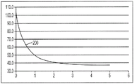
FIG. 2 is a graph illustrating a temperature profile in tissue formed by the prior art ablation device of FIG. 1;
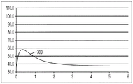
FIG. 3 is a graph illustrating a temperature profile in tissue formed by a prior art ablation device with cooling by unheated fluid;
FIG. 4 is a graph illustrating a temperature profile in tissue formed by the device of FIG. 3 after increasing the level of ablation energy;
FIG. 5 is a graph illustrating a temperature profile developed in tissue by an embodiment of the ablation device of the invention;
FIG. 6 is a side view of one embodiment of an ablation element having a closed-loop flow pattern; and
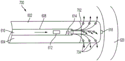
FIG. 7 is a side view of one embodiment of an ablation element having an open flow pattern.
Detailed Description
Certain exemplary embodiments will now be described to enable those skilled in the art to understand the principles of the devices and methods disclosed herein in general. The drawings illustrate one or more examples of these embodiments. Those skilled in the art will understand that: the apparatus and methods specifically described herein and illustrated in the accompanying drawings are non-limiting exemplary embodiments and the scope of the present invention is defined solely by the claims. Features illustrated or described in connection with one exemplary embodiment may be combined with features of other embodiments. Such modifications and variations are intended to be included within the scope of the present invention.
The terms "a" and "an" are used interchangeably and are equivalent to the term "one or more" as used in this application. Unless otherwise indicated, the terms "comprising", "having", "including" and "containing" should be construed as open-ended terms (i.e., meaning "including, but not limited to"). The terms "about" and "approximately" as used with respect to any value or range of values indicates that the value or range of values has a suitable dimensional tolerance such that the composition, component, or collection of elements still functions to achieve the intended purpose described herein. These terms generally mean that there is a range of variation of ± 10% around the central value. The components described herein as being coupled may be directly coupled, or the components may be indirectly coupled via one or more intermediate components. Unless otherwise indicated herein, any range of values recited herein is intended merely as a shorthand method of individually describing each separate value that falls within the range, and each separate value is incorporated into the specification as if it were individually recited. All methods described herein can be performed in any suitable order unless otherwise indicated herein or otherwise clearly contradicted by context. Unless otherwise claimed, any and all examples, or exemplary descriptions provided herein (e.g., "such as (subcas)") are intended merely to better illuminate the invention and do not pose a limitation on the scope of the invention. No language in the specification should be construed as indicating any non-claimed element as essential to the practice of the invention. Further, unless specifically indicated otherwise, when the term "saline" is used in conjunction with any embodiment herein, such embodiments are not limited to using only "saline" without another fluid. Other fluids may also typically be used in a similar manner.
As described above, conventional ablation techniques using devices similar to the ablation catheter 100 shown in fig. 1 can result in maximum heating of tissue at the interface of the ablation element, such as electrode 104, and the tissue, such as myocardium 106. Using such a device, a temperature profile 200, shown in fig. 2, can be generated that shows temperature (degrees celsius) as a function of depth (mm) from the tissue surface. As shown, the ablation catheter 100 can form a therapeutically treated lesion in tissue 1mm deep. I.e. the tissue depth reached by heating to a temperature above 50 ℃ is 1 mm. A temperature of 50 ℃ is used herein as a typical threshold in order to determine when a particular volume of tissue has achieved therapeutic treatment, i.e., has reached a thermal dose that causes necrosis within the tissue (see Nath, S. and Haines, D. E., prog. card. Dis. 37(4): 185-205 (1995) (Nathet al.). This temperature value is merely exemplary, however, as there are many different methods in the literature to determine the thermal dose provided, any of which may be used with the methods and apparatus of the present invention.
Referring back to fig. 2, the shallower treatment depth produced by the prior art ablation catheter 100 is generally effective only for shallow arrhythmogenic tissue, or, for example, in regions of the heart where the heart wall is very thin (e.g., a thinner atrial wall). As ablation techniques are increasingly used in the treatment of atrial fibrillation and other cardiac conditions, ablation therapy has been used in areas of much thicker tissue walls. One method for increasing the depth to which an ablation catheter can be heated is to cool the surface of an ablation element, such as electrode 104. To this end, fluid may be pumped down the ablation catheter to contact the ablation element disposed adjacent the distal end of the catheter. In some cases, the fluid may contact the rear surface of the ablation element and return back up the catheter body. In other cases, however, the fluid may exit the ablation catheter through one or more ports or apertures formed in the ablation element itself.
In either case, a fluid (e.g., saline) may be introduced into the ablation catheter at room temperature and is typically heated to a temperature near body temperature by the surrounding blood as the fluid moves through the body toward the distal end of the catheter. The flowing body temperature fluid may cool the ablation element and limit the temperature of the ablation element to a temperature of about body temperature, or 37 ℃.
Fig. 3 shows a typical temperature profile formed by such a device. As shown by curve 300, contacting the ablation element with body temperature fluid can effectively mitigate heating occurring at the interface between the ablation element and the tissue wall. However, such cooling also produces the effect of: the temperature of the entire heating field is reduced to the point where the effectiveness of the ablation treatment is compromised, i.e., only a small portion of the tissue is heated to the desired temperature above 50 ℃. This effect can also occur in areas of the heart (or other organ) where blood moving past the treatment site can cause effective localized cooling of the vessel or artery. For example, in atrial fibrillation, it may be necessary to perform ablation in the vicinity of the coronary sinus, and the large amount of blood flow in this region will effectively cool the heating field formed by any ablation device.
To compensate for this cooling effect, the radio frequency power level used to heat the tissue may be increased. Increasing the rf power level in combination with cooling the ablation element may, for example, produce the temperature profile 400 shown in fig. 4. The positive effect of increasing power is to increase the depth of the therapeutic treatment (e.g. to 2 mm), but also to generate a higher maximum temperature in the tissue. In addition, cooling of the ablation element may cause the location of the maximum temperature to be displaced inwardly of the tissue. Due to its deeper position, the maximum temperature can no longer be directly observed, which makes it difficult to control the balance between the amount of radio frequency heating and the amount of cooling provided by the fluid. In this case, the temperature within the tissue may exceed 100 ℃ at some locations. Tissue dehydrates or dries out and overheats beyond 100 ℃. This can produce charring and cause the impedance of the tissue to rise. As the impedance increases, the amount of electrical energy that can be passed through the tissue decreases. Thus, the impedance rise will effectively prevent any further ablation treatment, since the energy is no longer delivered deeper into the tissue. Further, such high temperatures may also cause excessive heating of any fluid in the tissue. In some instances, impedance peaks-or surge-like phase changes of the superheated fluid to steam-may occur. These small surges can lead to damage in the tissue wall and can lead to serious medical complications (e.g., to perforation in the heart wall, etc.).
To address these issues, the methods and devices provided herein enable control of the temperature and power level of the ablation element to thereby prevent undesirable temperature spikes while maintaining the depth of the treatment lesion formed during ablation therapy. FIG. 5 illustrates an exemplary temperature profile 500 that can be achieved using the methods and apparatus described herein. In one embodiment, a heating element may be implemented in the ablation device to cool the ablation element at a controlled and desired temperature. The temperature of the fluid may be selected such that the ablation element is cooled to a temperature of less than about 100 ℃. More preferably, the fluid may be cooled to a temperature between about 20 ℃ and 100 ℃. Even more preferably, the fluid may be cooled to a temperature between 37 ℃ and 100 ℃.
For example and as shown, the ablation element may be cooled to a temperature of about 60 ℃. Adjusting the temperature of the ablation element to this level not only prevents dehydration and impedance rise due to heating to temperatures above 100 ℃, but also allows deeper therapeutic heating at lower rf power levels. For example, curve 500 shows that tissue having a depth of 5mm can be heated to a temperature above 50 ℃ without the tissue temperature rising above about 80 ℃. Although 60 ℃ is considered a typical temperature, any temperature between 37 ℃ and 100 ℃ is optional. For example, a temperature of 40, 50, 60, 70, 80, or 90 ℃ may be selected. One skilled in the art can coordinate the balance between the selection of the fluid temperature (which may approach the ablation element temperature since the flowing fluid will cool the ablation element to about the same temperature) and the selection of the rf power level to create a desired depth of treatment lesion without any portion of the tissue being heated above 100 ℃.
A variety of different devices and methods may be employed to heat the cooling fluid to the desired temperature. Fig. 6 illustrates one embodiment of an ablation device 600. Device 600 includes an elongated body that may be rigid or flexible and may be formed from a variety of biocompatible materials. For example, the elongate body 602 may be a flexible catheter body, or may be a rigid body disposed at the distal end of the catheter for guiding the elongate body to a treatment site. The elongate body 602 may also include an internal lumen 604 extending therethrough that may be configured to provide a pathway for fluid flowing through the elongate body. Further, the particular size of the elongate body may depend on a variety of factors, including the type and location of tissue to be treated, and the like. The following description is exemplary only: in one embodiment, a very small elongated body may be used to access the patient's heart. In such embodiments, the elongate body of suitable dimensions may be, for example, a catheter having a diameter of about 8fr (French) ("French" is a measure used in the catheter industry to describe the size of the catheter in terms of units of three times the diameter of the catheter in mm). The elongate body may be formed of a conductive material such that the elongate body may conduct electrical energy along its length to an ablation element disposed thereon. Alternatively, the elongate body may be formed from or coated with an insulating material and any electrical communication may be achieved between any components coupled to the elongate body by electrical connection means running along or within the elongate body.
The elongate body 602 may also include an ablation element 606 disposed along its length adjacent its distal end, as shown, in some embodiments the ablation element 606 may be positioned at the distal end of the elongate body 602. The ablation element 606 may be formed from a variety of materials suitable for conducting electrical current. Any metal or metal salt may be used. In addition to stainless steel, typical metals include platinum, gold, or silver, and typical metal salts include silver/silver chloride. In one embodiment, the electrodes may be formed of silver/silver chloride. As is well known to those skilled in the art, metal electrodes exhibit voltage potentials that are different from the surrounding tissue and/or fluid. Application of current through this voltage difference can result in energy dissipation at the electrode/tissue interface, which can exacerbate overheating of the tissue surrounding the electrode. One advantage of using metal salts such as silver/silver chloride is that: which has a higher exchange current density. Thus, only a small voltage drop will allow a large amount of current to pass through such electrodes into the tissue, thereby minimizing energy consumption at the interface. Thus, an electrode formed from a metal salt such as silver/silver chloride will mitigate the excess energy generated at the tissue interface and thus produce a more desirable therapeutic temperature profile, even when there is no fluid flow around the electrode.
In some embodiments, an ablation element 606 may be disposed at the distal end of the elongate body 602. Ablation elements 606 can have a variety of shapes, but in some embodiments, can be shaped so as to form a blunt distal tip of device 600. Thus, the ablation element 606 may be configured to be pressed against or positioned adjacent to a tissue wall without penetrating into the tissue wall. Further, the ablation element 606 may be formed from a non-porous material, or in some embodiments, the ablation element 606 may have one or more outlet ports or apertures formed thereon to provide fluid communication between the inner lumen and the tissue and/or fluid surrounding the ablation element.
In some embodiments, the inner lumen of the elongate body 602 can include a delivery lumen 608 configured to provide a passageway for fluid flow from the proximal end to the distal end, and the inner lumen can include a return lumen formed by an annular space between the delivery lumen 608 and an inner wall of the inner lumen 604. The return lumen may be configured to receive fluid at its distal end and deliver the fluid back to the proximal end of the elongate body 602. This allows fluid to circulate through the elongate body without releasing the fluid to the surrounding tissue. Similar to the elongate body 602, the delivery lumen 608 can be formed from a variety of materials that are rigid, flexible, polymeric, metallic, conductive, or insulative. Further, the delivery lumen 608 can be positioned within the inner lumen 604 of the elongate body 602 such that the delivery lumen does not move relative to the elongate body, or can be allowed to float freely within the elongate body 602. In some embodiments, the delivery lumen 608 may be a hollow conduit disposed within the inner lumen of the elongate body. Further, in certain embodiments, the return lumen may be a separate hollow conduit disposed within the interior lumen 604 of the elongate body.
In some embodiments, the delivery lumen 608 may house a heating assembly or heater element 612 disposed adjacent to the distal end of the delivery lumen and configured to heat fluid flowing through the delivery lumen. The heating assembly 612 may be connected to a power supply and controller coupled to the proximal end of the elongate body 602. Multiple heating assemblies may be used to heat fluid flowing through the delivery lumen 608, including those described in U.S. patent No. 6,328,725 to Curley et al and U.S. patent application No. 13/445,036, entitled "method and apparatus for heating fluid during fluid enhanced ablation therapy," filed concurrently with the present application. The entire disclosure of each of these references is incorporated herein by reference. For example, the heater element 612 may be a resistive coil disposed within the delivery lumen 608. However, in other embodiments, a heating assembly 612 formed of one or more wires that can be used to pass radio frequency electrical energy through the fluid flowing through the delivery lumen is suspended in the delivery lumen 608, thereby heating the fluid under the influence of the fluid's intrinsic resistivity.
In certain embodiments, the delivery lumen 608 may also house a temperature sensor configured to detect the temperature of the fluid flowing through the delivery lumen 608 after the fluid is heated by the heating assembly 612. For this reason, in some embodiments, the temperature sensor 614 may be positioned at a distal end of the heating assembly 612 and may be separated from the heating assembly by a sufficient distance to allow the fluids to mix after passing through the heating assembly (e.g., the distance is about 1 mm). The temperature sensor 614 may take a variety of forms, and in some embodiments may be a fine wire thermocouple. The temperature sensor 614 may be connected to a controller that may use the sensed fluid temperature to regulate the heating assembly 612.
During use, a fluid (e.g., saline) may be pumped through the delivery lumen 608 from the proximal end to the distal end positioned adjacent to the ablation element 606. Fluid may pass through the heating element 612 and be heated to a desired temperature, such as any temperature below 100 ℃, or between about 40 ℃ and about 90 ℃, or between about 50 ℃ and about 80 ℃, or between about 60 ℃ and about 70 ℃. In some embodiments, an additional temperature sensor (not shown) may be positioned in the delivery lumen 608 at a location proximal to the heating assembly 612 in order to determine the initial temperature of the fluid flowing through the delivery lumen 608 (and thus the power output required by the heating assembly 612). After being heated by the heating assembly 612, the fluids may mix and exit the delivery lumen 608 near the distal end of the elongate body 602 adjacent the ablation element. As indicated by flow arrows 616, the fluid may contact the inner surface of the ablation element and then be directed back through the return lumen toward the proximal end of the elongate body 602. The movement of the fluid may convectively remove heat from the ablation element 606, thereby regulating its temperature. With a sufficiently large flow rate, the ablation element 606 may be regulated to the same temperature as the fluid exiting the delivery lumen 608.
To verify the effectiveness of the temperature regulation, the device 600 may also include an external temperature sensor 618 disposed on the distal end of the device 600. In some embodiments, the temperature sensor 618 may be recessed within the ablation element 606 such that it does not protrude from its distal end. In other embodiments where the ablation element 606 is formed from a metal or other thermally conductive material, the temperature sensor 618 may be positioned inside the inner lumen 604 in contact with the proximal surface of the ablation element 606. Regardless of the location, the temperature sensor 618 may be configured to detect the temperature at the interface between the ablation element 606 and the tissue surface 620. Sensing the temperature at this location may confirm that the ablation element 606 is cooled to the temperature of the fluid flowing out of the delivery lumen 608.
FIG. 7 illustrates another embodiment of an ablation element having an open flow pattern as opposed to the closed flow pattern illustrated in FIG. 6. As shown, the device 700 may include many of the same components as the device shown in fig. 6. For example, the device 700 may include an elongate body 602 having an inner lumen 604, a delivery lumen 608 disposed within the inner lumen 604 and having its own inner lumen 610, a heating assembly 612, and a temperature sensor 614 housed within the inner lumen 610, and in some embodiments, one or more additional temperature sensors 618.
The devices shown in fig. 6 and 7 can both be used to perform ablation therapy and prevent overheating of the tissue while enabling therapeutic treatment at a greater depth than previously possible. However, in some embodiments, it may be preferable to use a closed circuit device 600 rather than an open circuit device 700. For example, in embodiments where the temperature of the fluid introduced from the delivery lumen 608 is sufficiently high, it may be undesirable to allow the fluid to flow into tissue downstream or around the ablation device, as this temperature may in some cases damage the tissue or cause blood clots to form. Thus, it may be desirable to collect the heated fluid at the proximal end of the device, rather than introduce the fluid into the patient's body. However, this will also vary depending on the location and specific anatomical features of the treatment site. For example, areas with higher blood flow can dissipate heat from high temperature fluids without medical complications.
The above-described devices may be used in a variety of procedures requiring ablation of tissue within the body. For example, the devices and methods disclosed herein may be particularly useful in cardiac ablation procedures. Surgical procedures for treating atrial fibrillation and flutter, such as the Maze procedure, typically require ablation of a large number of anatomical features of the heart at locations where the tissue wall has a variable thickness. The methods and devices of the present invention enable an operator to ablate tissue of various geometries at a minimum radio frequency power level without overheating at any depth. For example, during ablation of a thicker wall of the myocardium, a device similar to device 600 may be configured to be introduced into the patient via an access port or other opening formed through one or more layers of the tissue, or via a natural orifice (i.e., via an endoscope). The device may then be delivered directly to any treatment site within the body, or using existing pathways within the body (e.g., passing the device through a patient's blood vessel into the heart). Once in the vicinity of the desired treatment site, the ablation elements of the device may be positioned with the assistance of sensing electrodes or other positioning instruments, and the distal tips of the ablation elements may be pressed against the tissue at a particular location. Further, in many embodiments, the elongate body and/or ablation element can have a blunt distal end such that the elongate body and/or ablation element can be pressed against the tissue wall without penetrating the tissue. After positioning, radiofrequency energy can be delivered into the tissue wall while fluid is delivered through the elongate body, e.g., through the delivery lumen. The fluid may be heated by a heating assembly positioned in a distal portion of the elongate body, e.g., within a distal portion of the delivery lumen. Fluid may contact the ablation element and flow through ports formed in the ablation element or back to the proximal end of the elongate member to convectively remove heat away from the ablation element. Delivering the heated fluid is effective to adjust the temperature of the ablation element to match the temperature of the heated fluid. The controlled and elevated operating temperature allows ablation therapy to be performed with efficient levels of radio frequency power and avoids heating the tissue to temperatures above a threshold level, such as 100 ℃.
The above exemplary embodiments describe the treatment of cardiac tissue. Although this is one contemplated use, the methods and devices of the present invention are equally applicable to other areas of a patient's body. Thus, the devices described herein can be formed in a variety of sizes and from materials suitable for use in a variety of areas of a patient's body.
Furthermore, one skilled in the art will recognize that: heating mechanisms that result in the generation of sufficient superheat within the target tissue to destroy the tissue also include other forms of energy. Ultrasonic vibrational energy is known to be absorbed by tissue and converted to heat, as is the electromagnetic energy of microwaves and light waves. Other embodiments may employ an ultrasonic transducer, a microwave antenna, or a light wave diffuser as the emitter disposed in the distal end of the elongated body. Lightwave electromagnetic energy falls within a spectral range spanning visible, near infrared, and far infrared light, and may be generated by a filament, an arc lamp, various forms of lasers (e.g., diodes, semiconductors, or pumps), or by other means. Similarly, the distal end of the elongate body may be adapted to include a heating mechanism, such as a resistive wire, to heat tissue by conduction. Regardless of which ablation element is used, injecting heated fluid into the tissue at a location adjacent any of the ablation elements will improve the ability of each device to heat a larger volume of tissue. Thus, the heating assemblies disclosed herein may be adapted for use with devices that use any of these other alternative ablation energy sources. Those skilled in the art also recognize that: the delivery device may be any standard medical delivery device depending on the tissue to be treated. Other alternative embodiments may include a metallic or non-metallic needle, sheath or introducer.
The device disclosed herein may be designed to be disposed of after a single use, or it may be designed to be used multiple times. In either case, however, the device may be reconditioned for reuse after at least one use. The readjustment may comprise any combination of the following steps: the device is disassembled, then cleaned or replaced with a particular piece, and then reassembled again. In particular, the device may be disassembled, and any number of the particular pieces or parts of the device may be selectively replaced or removed in any combination. Upon cleaning and/or replacement of particular parts, the device may be reassembled for subsequent use either at a reconditioning facility, or by a surgical team immediately prior to a surgical procedure. Those skilled in the art will appreciate that: the device can be reconditioned using a variety of techniques for disassembly, cleaning/replacement, and reassembly. Devices utilizing this technique and thus reconditioned are all within the scope of the present invention.
For example, the devices disclosed herein may be partially or fully disassembled. In particular, the elongate body 602 of the medical device 600 shown in fig. 6 may be detachable from any control handle or other attachment component, or the elongate body 602 may be separable from the ablation element and/or any delivery lumen extending therethrough. Similarly, the heating assembly or element 612 and the temperature sensor 614 can be separate from the delivery lumen 608 and/or the elongate body 602 for cleaning and/or replacement. These are merely exemplary disassembly steps and any components of the device may be configured to be separated from the device for cleaning and/or replacement.
Preferably, the devices disclosed herein will be treated prior to surgery. First, a new or used instrument can be set up and cleaned (if necessary). The instrument may then be sterilized. In one sterilization technique, the instrument is placed in a closed and sealed container, such as a plastic or TYVEK (TYVEK) bag. The container and its contents may then be placed in a field of radiation that is transparent to the container, such as gamma radiation, x-rays, or high-energy electrons. The radiation may kill bacteria on the instrument and in the container. The sterilized instrument may then be stored in a sterile container. The sealed container may maintain the sterility of the instrument until it is opened in a medical facility.
In various embodiments, the device is preferably sterilized, which may be performed in any of a number of ways known to those skilled in the art, including β radiation or gamma radiation, ethylene oxide, steam, and liquid baths (e.g., cold immersion).
All publications and references cited herein are expressly incorporated herein by reference in their entirety. Based on the above embodiments, one skilled in the art should appreciate further features and advantages of the invention. Accordingly, the invention is not to be limited by what has been particularly shown and described, except as indicated by the appended claims.
Claims (38)
1. An ablation device, comprising:
an elongate body having a blunt distal end portion and an inner lumen configured to deliver fluid therefrom;
an ablation element positioned at the distal end of the elongate body, the ablation element configured to emit ablation energy;
a heater element configured to heat fluid within the inner lumen to a temperature above 37 ℃ and below 100 ℃; and
a temperature sensor;
wherein the elongate body is configured such that fluid can circulate through the elongate body and be received back at its proximal end without being released into surrounding tissue.
2. The device of claim 1, wherein the temperature sensor is disposed within the inner lumen of the elongate body and in contact with the ablation element.
3. The device of claim 2, further comprising a controller configured to:
detecting a temperature of the ablation element using the temperature sensor;
adjusting output levels of the ablation element and the heater element to maintain a temperature of the ablation element above 37 ℃ and below 100 ℃.
4. The device of claim 1, wherein the temperature sensor is positioned adjacent the distal end of the inner lumen at a location distal to the heater element.
5. The device of claim 1, wherein the heater element is disposed within the inner lumen to heat a fluid.
6. The device of claim 1, wherein the ablation element is a transmitting electrode for delivering electrical energy.
7. The apparatus of claim 6, further comprising a common electrode configured to be positioned remotely from the emitter electrode.
8. The apparatus of claim 1, further comprising:
a delivery lumen disposed within the inner lumen of the elongate body and configured to deliver fluid from the proximal end to the distal end of the elongate body; and
a return lumen disposed within the inner lumen of the elongate body configured to receive fluid delivered to the distal end of the elongate body and return the fluid to the proximal end of the elongate body.
9. The device of claim 8, wherein the return lumen is defined by an annular space between the delivery lumen and an inner wall of the inner lumen of the elongate body.
10. The device of claim 8, wherein the delivery lumen and return lumen are each discrete hollow tubes disposed in the interior lumen of the elongate body.
11. The device of claim 8, wherein the delivery lumen is positioned in the inner lumen of the elongate body such that it does not move relative to the elongate body.
12. The device of claim 8, wherein the delivery lumen is free floating in the inner lumen of the elongate body.
13. The device of claim 1, wherein the ablation element is formed of a non-porous material.
14. An ablation device, comprising:
an elongate body having a blunt distal end portion and an inner lumen configured to deliver fluid therefrom;
an ablation element positioned at the distal end of the elongate body, the ablation element configured to emit ablation energy;
at least one wire extending through the inner lumen and configured to pass RF electrical energy through a fluid flowing through the inner lumen to heat the fluid to a temperature above 37 ℃ and below 100 ℃; and
wherein the elongate body is configured such that fluid can circulate through the elongate body and be received back at its proximal end without being released into surrounding tissue.
15. The device of claim 14, further comprising a temperature sensor disposed on a distal end of the elongated body.
16. The device of claim 14, further comprising a temperature sensor disposed within the inner lumen of the elongate body and in contact with the ablation element.
17. The device of claim 16, further comprising a controller configured to:
detecting a temperature of the ablation element using the temperature sensor;
adjusting output levels of the ablation element and the heater element to maintain a temperature of the ablation element above 37 ℃ and below 100 ℃.
18. The device of claim 14, further comprising a temperature sensor positioned adjacent the distal end of the inner lumen at a location distal of the heater element.
19. The device of claim 14, wherein the ablation element is a transmitting electrode for delivering electrical energy.
20. The apparatus of claim 19, further comprising a common electrode configured to be positioned remotely from the emitter electrode.
21. The apparatus of claim 14, further comprising:
a delivery lumen disposed within the inner lumen of the elongate body and configured to deliver fluid from the proximal end to the distal end of the elongate body; and
a return lumen disposed within the inner lumen of the elongate body configured to receive fluid delivered to the distal end of the elongate body and return the fluid to the proximal end of the elongate body.
22. The device of claim 21, wherein the return lumen is defined by an annular space between the delivery lumen and an inner wall of the inner lumen of the elongate body.
23. The device of claim 21, wherein the delivery lumen and return lumen are each discrete hollow tubes disposed in the interior lumen of the elongate body.
24. The device of claim 21, wherein the delivery lumen is positioned in the inner lumen of the elongate body such that it does not move relative to the elongate body.
25. The device of claim 21, wherein the delivery lumen is free floating in the inner lumen of the elongate body.
26. The device of claim 14, wherein the ablation element is formed of a non-porous material.
27. An ablation device, comprising:
an elongate body having a blunt distal end portion and an inner lumen configured to deliver fluid therefrom;
a transmit electrode positioned at a distal end of the elongate body for delivering electrical energy;
at least one wire extending through the inner lumen and configured to pass RF electrical energy through a fluid flowing through the inner lumen to heat the fluid to a temperature above 37 ℃ and below 100 ℃; and
wherein the elongate body is configured such that fluid can circulate through the elongate body and be received back at its proximal end without being released into surrounding tissue.
28. The apparatus of claim 27, further comprising a common electrode configured to be positioned remotely from the emitter electrode.
29. The device of claim 27, further comprising a temperature sensor disposed on a distal end of the elongated body.
30. The device of claim 27, further comprising a temperature sensor disposed within the inner lumen of the elongate body and in contact with the ablation element.
31. The device of claim 30, further comprising a controller configured to:
detecting a temperature of the ablation element using the temperature sensor;
adjusting output levels of the ablation element and the heater element to maintain a temperature of the ablation element above 37 ℃ and below 100 ℃.
32. The device of claim 27, further comprising a temperature sensor positioned adjacent the distal end of the inner lumen at a location distal of the heater element.
33. The apparatus of claim 27, further comprising:
a delivery lumen disposed within the inner lumen of the elongate body and configured to deliver fluid from the proximal end to the distal end of the elongate body; and
a return lumen disposed within the inner lumen of the elongate body configured to receive fluid delivered to the distal end of the elongate body and return the fluid to the proximal end of the elongate body.
34. The device of claim 33, wherein the return lumen is defined by an annular space between the delivery lumen and an inner wall of the inner lumen of the elongate body.
35. The device of claim 33, wherein the delivery lumen and return lumen are each discrete hollow tubes disposed in the interior lumen of the elongate body.
36. The device of claim 33, wherein the delivery lumen is positioned in the inner lumen of the elongate body such that it does not move relative to the elongate body.
37. The device of claim 33, wherein the delivery lumen is free floating in the inner lumen of the elongate body.
38. The device of claim 27, wherein the ablation element is formed of a non-porous material.
Applications Claiming Priority (3)
| Application Number | Priority Date | Filing Date | Title |
|---|---|---|---|
| US201161474574P | 2011-04-12 | 2011-04-12 | |
| US61/474574 | 2011-04-12 | ||
| CN201280028609.9A CN103596513B (en) | 2011-04-12 | 2012-04-12 | Method and apparatus for controlling ablation |
Related Parent Applications (1)
| Application Number | Title | Priority Date | Filing Date |
|---|---|---|---|
| CN201280028609.9A Division CN103596513B (en) | 2011-04-12 | 2012-04-12 | Method and apparatus for controlling ablation |
Publications (2)
| Publication Number | Publication Date |
|---|---|
| CN107753098A CN107753098A (en) | 2018-03-06 |
| CN107753098B true CN107753098B (en) | 2020-06-30 |
Family
ID=47006969
Family Applications (10)
| Application Number | Title | Priority Date | Filing Date |
|---|---|---|---|
| CN201711019074.XA Expired - Fee Related CN107753098B (en) | 2011-04-12 | 2012-04-12 | Method and apparatus for controlling ablation therapy |
| CN201280028609.9A Expired - Fee Related CN103596513B (en) | 2011-04-12 | 2012-04-12 | Method and apparatus for controlling ablation |
| CN201710537279.0A Active CN107334529B (en) | 2011-04-12 | 2012-04-12 | Methods and devices for using a degassing fluid with a fluid enhanced ablation device |
| CN201280028620.5A Expired - Fee Related CN103619276B (en) | 2011-04-12 | 2012-04-12 | Apparatus and method for carrying out remote temperature monitoring in the enhanced ablation of fluid |
| CN201280028621.XA Expired - Fee Related CN103764056B (en) | 2011-04-12 | 2012-04-12 | Devices and methods for shaping therapy in fluid enhanced ablation |
| CN201611215279.0A Active CN106901830B (en) | 2011-04-12 | 2012-04-12 | Device for shaping therapy in fluid enhanced ablation |
| CN201280028612.0A Active CN103619275B (en) | 2011-04-12 | 2012-04-12 | Method and apparatus for using the enhanced ablating device of fluid deaeration fluid |
| CN202010767280.4A Pending CN112057159A (en) | 2011-04-12 | 2012-04-12 | Method and apparatus for heating fluid in fluid enhanced ablation therapy |
| CN201280028611.6A Active CN103764055B (en) | 2011-04-12 | 2012-04-12 | The method and apparatus heated is carried out for convection cell in fluid enhancement mode ablation |
| CN201610676584.3A Active CN106420040B (en) | 2011-04-12 | 2012-04-12 | Method and apparatus for heating fluid in fluid enhanced ablation therapy |
Family Applications After (9)
| Application Number | Title | Priority Date | Filing Date |
|---|---|---|---|
| CN201280028609.9A Expired - Fee Related CN103596513B (en) | 2011-04-12 | 2012-04-12 | Method and apparatus for controlling ablation |
| CN201710537279.0A Active CN107334529B (en) | 2011-04-12 | 2012-04-12 | Methods and devices for using a degassing fluid with a fluid enhanced ablation device |
| CN201280028620.5A Expired - Fee Related CN103619276B (en) | 2011-04-12 | 2012-04-12 | Apparatus and method for carrying out remote temperature monitoring in the enhanced ablation of fluid |
| CN201280028621.XA Expired - Fee Related CN103764056B (en) | 2011-04-12 | 2012-04-12 | Devices and methods for shaping therapy in fluid enhanced ablation |
| CN201611215279.0A Active CN106901830B (en) | 2011-04-12 | 2012-04-12 | Device for shaping therapy in fluid enhanced ablation |
| CN201280028612.0A Active CN103619275B (en) | 2011-04-12 | 2012-04-12 | Method and apparatus for using the enhanced ablating device of fluid deaeration fluid |
| CN202010767280.4A Pending CN112057159A (en) | 2011-04-12 | 2012-04-12 | Method and apparatus for heating fluid in fluid enhanced ablation therapy |
| CN201280028611.6A Active CN103764055B (en) | 2011-04-12 | 2012-04-12 | The method and apparatus heated is carried out for convection cell in fluid enhancement mode ablation |
| CN201610676584.3A Active CN106420040B (en) | 2011-04-12 | 2012-04-12 | Method and apparatus for heating fluid in fluid enhanced ablation therapy |
Country Status (9)
| Country | Link |
|---|---|
| US (19) | US8702697B2 (en) |
| EP (8) | EP2696787B1 (en) |
| JP (14) | JP6170037B2 (en) |
| KR (9) | KR102112356B1 (en) |
| CN (10) | CN107753098B (en) |
| AU (7) | AU2012242853B2 (en) |
| BR (5) | BR112013026176A2 (en) |
| ES (4) | ES2864589T3 (en) |
| WO (5) | WO2012142296A1 (en) |
Families Citing this family (91)
| Publication number | Priority date | Publication date | Assignee | Title |
|---|---|---|---|---|
| US7918795B2 (en) | 2005-02-02 | 2011-04-05 | Gynesonics, Inc. | Method and device for uterine fibroid treatment |
| US11259825B2 (en) | 2006-01-12 | 2022-03-01 | Gynesonics, Inc. | Devices and methods for treatment of tissue |
| US9403029B2 (en) * | 2007-07-18 | 2016-08-02 | Visualase, Inc. | Systems and methods for thermal therapy |
| JP5400784B2 (en) * | 2007-10-09 | 2014-01-29 | ボストン サイエンティフィック リミテッド | Electrophysiological electrode and device comprising electrophysiological electrode |
| US9023030B2 (en) | 2007-10-09 | 2015-05-05 | Boston Scientific Scimed, Inc. | Cooled ablation catheter devices and methods of use |
| US8088072B2 (en) | 2007-10-12 | 2012-01-03 | Gynesonics, Inc. | Methods and systems for controlled deployment of needles in tissue |
| WO2016164930A1 (en) * | 2015-04-10 | 2016-10-13 | Angiodynamics Inc. | System and method for irreversible electroporation with thermally controlled electrodes |
| AU2009313324A1 (en) * | 2008-11-06 | 2010-05-14 | Nxthera, Inc. | Systems and methods for treatment of BPH |
| US8262574B2 (en) | 2009-02-27 | 2012-09-11 | Gynesonics, Inc. | Needle and tine deployment mechanism |
| WO2010138919A2 (en) | 2009-05-28 | 2010-12-02 | Angiodynamics, Inc. | System and method for synchronizing energy delivery to the cardiac rhythm |
| US8926605B2 (en) | 2012-02-07 | 2015-01-06 | Advanced Cardiac Therapeutics, Inc. | Systems and methods for radiometrically measuring temperature during tissue ablation |
| US9226791B2 (en) | 2012-03-12 | 2016-01-05 | Advanced Cardiac Therapeutics, Inc. | Systems for temperature-controlled ablation using radiometric feedback |
| US9277961B2 (en) | 2009-06-12 | 2016-03-08 | Advanced Cardiac Therapeutics, Inc. | Systems and methods of radiometrically determining a hot-spot temperature of tissue being treated |
| US8954161B2 (en) | 2012-06-01 | 2015-02-10 | Advanced Cardiac Therapeutics, Inc. | Systems and methods for radiometrically measuring temperature and detecting tissue contact prior to and during tissue ablation |
| US9895189B2 (en) | 2009-06-19 | 2018-02-20 | Angiodynamics, Inc. | Methods of sterilization and treating infection using irreversible electroporation |
| US10588609B2 (en) | 2010-02-04 | 2020-03-17 | Procept Biorobotics Corporation | Gene analysis and generation of stem cell methods and apparatus |
| WO2016037132A1 (en) | 2014-09-05 | 2016-03-10 | Procept Biorobotics Corporation | Gene analysis and generation of stem cell methods and apparatus |
| US20140171806A1 (en) * | 2012-12-17 | 2014-06-19 | Biosense Webster (Israel), Ltd. | Optical lesion assessment |
| US11490957B2 (en) | 2010-06-16 | 2022-11-08 | Biosense Webster (Israel) Ltd. | Spectral sensing of ablation |
| US10314650B2 (en) | 2010-06-16 | 2019-06-11 | Biosense Webster (Israel) Ltd. | Spectral sensing of ablation |
| WO2012051433A2 (en) | 2010-10-13 | 2012-04-19 | Angiodynamics, Inc. | System and method for electrically ablating tissue of a patient |
| AU2012242853B2 (en) | 2011-04-12 | 2016-10-27 | Thermedical, Inc. | Methods and devices for heating fluid in fluid enhanced ablation therapy |
| DK2755614T3 (en) | 2011-09-13 | 2017-12-04 | Nxthera Inc | PROSTATE TREATMENT SYSTEMS |
| US9078665B2 (en) | 2011-09-28 | 2015-07-14 | Angiodynamics, Inc. | Multiple treatment zone ablation probe |
| US10335222B2 (en) | 2012-04-03 | 2019-07-02 | Nxthera, Inc. | Induction coil vapor generator |
| US10022176B2 (en) | 2012-08-15 | 2018-07-17 | Thermedical, Inc. | Low profile fluid enhanced ablation therapy devices and methods |
| US8992427B2 (en) | 2012-09-07 | 2015-03-31 | Gynesonics, Inc. | Methods and systems for controlled deployment of needle structures in tissue |
| US10195467B2 (en) * | 2013-02-21 | 2019-02-05 | Boston Scientific Scimed, Inc. | Ablation catheter system with wireless radio frequency temperature sensor |
| CA2905508A1 (en) | 2013-03-14 | 2014-09-25 | Nxthera, Inc. | Systems and methods for treating prostate cancer |
| US9610396B2 (en) | 2013-03-15 | 2017-04-04 | Thermedical, Inc. | Systems and methods for visualizing fluid enhanced ablation therapy |
| US9033972B2 (en) | 2013-03-15 | 2015-05-19 | Thermedical, Inc. | Methods and devices for fluid enhanced microwave ablation therapy |
| US9579118B2 (en) * | 2013-05-01 | 2017-02-28 | Ethicon Endo-Surgery, Llc | Electrosurgical instrument with dual blade end effector |
| EP3041422A4 (en) | 2013-09-06 | 2017-04-12 | Procept Biorobotics Corporation | Automated image-guided tissue resection and treatment |
| PL2859860T3 (en) * | 2013-10-08 | 2017-12-29 | Erbe Elektromedizin Gmbh | Multifunctional instrument |
| US9968395B2 (en) | 2013-12-10 | 2018-05-15 | Nxthera, Inc. | Systems and methods for treating the prostate |
| CN108635041B (en) | 2013-12-10 | 2021-04-13 | 恩克斯特拉公司 | Steam ablation system |
| US10617805B2 (en) | 2014-03-20 | 2020-04-14 | Exploramed Nc7, Inc. | Fluid measuring reservoir for breast pumps |
| WO2015153815A1 (en) * | 2014-04-01 | 2015-10-08 | Gregory Brucker | Temperature-responsive irrigated ablation electrode with reduced coolant flow and related methods for making and using |
| BR112016031037B1 (en) | 2014-06-30 | 2023-02-07 | Procept Biorobotics Corporation | DEVICE FOR ABLATING VASCULAR TISSUE |
| EP3174858B1 (en) | 2014-07-31 | 2019-04-17 | Basf Se | Process for preparing pyrazoles |
| CN114224438A (en) | 2014-09-05 | 2022-03-25 | 普罗赛普特生物机器人公司 | Physician-controlled tissue ablation in conjunction with treatment mapping of target organ images |
| WO2016081611A1 (en) | 2014-11-19 | 2016-05-26 | Advanced Cardiac Therapeutics, Inc. | High-resolution mapping of tissue with pacing |
| CA2967829A1 (en) | 2014-11-19 | 2016-05-26 | Advanced Cardiac Therapeutics, Inc. | Systems and methods for high-resolution mapping of tissue |
| EP3220843B1 (en) | 2014-11-19 | 2020-01-01 | EPiX Therapeutics, Inc. | Ablation devices and methods of using a high-resolution electrode assembly |
| US10342593B2 (en) | 2015-01-29 | 2019-07-09 | Nxthera, Inc. | Vapor ablation systems and methods |
| US9636164B2 (en) | 2015-03-25 | 2017-05-02 | Advanced Cardiac Therapeutics, Inc. | Contact sensing systems and methods |
| GB2536690B (en) * | 2015-03-26 | 2017-05-10 | Cook Medical Technologies Llc | Medical ablation system and method with reduced stray heating |
| EP4039287A1 (en) * | 2015-04-08 | 2022-08-10 | Willow Innovations, Inc. | Fluid measuring reservoir for breast pumps |
| AU2016260784B2 (en) | 2015-05-11 | 2020-03-12 | Basf Se | Process for preparing 4-amino-pyridazines |
| BR112017024245A2 (en) | 2015-05-13 | 2018-07-17 | Nxthera, Inc. | "method for treating overactive bladder, and steam dispensing system". |
| BR112018014357B8 (en) | 2016-02-02 | 2022-09-06 | Basf Se | PROCESS FOR THE PREPARATION OF A PYRAZOLE COMPOUND AND COMPOSITION |
| KR20180124070A (en) | 2016-03-15 | 2018-11-20 | 에픽스 테라퓨틱스, 인크. | Improved apparatus, systems and methods for irrigation ablation |
| US11172821B2 (en) | 2016-04-28 | 2021-11-16 | Medtronic Navigation, Inc. | Navigation and local thermometry |
| US20170325869A1 (en) * | 2016-05-10 | 2017-11-16 | Covidien Lp | Methods of ablating tissue |
| CA3025213A1 (en) * | 2016-05-25 | 2017-11-30 | Samuel Victor Lichtenstein | System for treating unwanted tissue |
| US9743984B1 (en) * | 2016-08-11 | 2017-08-29 | Thermedical, Inc. | Devices and methods for delivering fluid to tissue during ablation therapy |
| CN106388933B (en) * | 2016-09-14 | 2017-10-10 | 上海睿刀医疗科技有限公司 | Electrode for irreversible electroporation device |
| CN109788982B (en) * | 2016-10-04 | 2021-11-02 | 圣犹达医疗用品心脏病学部门有限公司 | Ablation catheter tip |
| CA3043314A1 (en) | 2016-11-11 | 2018-05-17 | Gynesonics, Inc. | Controlled treatment of tissue and dynamic interaction with, and comparison of, tissue and/or treatment data |
| CA3043490A1 (en) | 2016-11-14 | 2018-05-17 | Gynesonics, Inc. | Methods and systems for real-time planning and monitoring of ablation needle deployment in tissue |
| US10905492B2 (en) | 2016-11-17 | 2021-02-02 | Angiodynamics, Inc. | Techniques for irreversible electroporation using a single-pole tine-style internal device communicating with an external surface electrode |
| CN110177508B (en) | 2016-12-21 | 2022-10-28 | 波士顿科学医学有限公司 | Steam ablation system and method |
| US10751107B2 (en) | 2017-01-06 | 2020-08-25 | Boston Scientific Scimed, Inc. | Transperineal vapor ablation systems and methods |
| EP3565486B1 (en) | 2017-01-06 | 2021-11-10 | Dfine, Inc. | Osteotome with a distal portion for simultaneous advancement and articulation |
| US11147610B2 (en) * | 2017-02-10 | 2021-10-19 | Biosense Webster (Israel) Ltd. | Tissue thickness using pulsed power |
| CN106725827B (en) * | 2017-03-02 | 2023-11-17 | 上海伴诚医疗科技有限公司 | Intracranial hematoma removing hemostat and intracranial hematoma removing hemostatic device |
| EP3614946B1 (en) | 2017-04-27 | 2024-03-20 | EPiX Therapeutics, Inc. | Determining nature of contact between catheter tip and tissue |
| KR20200004362A (en) | 2017-05-04 | 2020-01-13 | 지네소닉스, 인크. | Monitoring method of ablation process by Doppler ultrasound |
| AU2018288848B2 (en) | 2017-06-20 | 2021-02-04 | AEGEA Medical, Inc | Induction coil assembly for uterine ablation and method |
| US10058372B1 (en) * | 2017-08-17 | 2018-08-28 | John H. Shadduck | Medical ablation devices and methods |
| CN109549703B (en) * | 2017-09-25 | 2022-04-01 | 上海微创电生理医疗科技股份有限公司 | Cryoablation system and electrophysiology catheter thereof |
| US20190192220A1 (en) * | 2017-12-27 | 2019-06-27 | Medlumics S.L. | Ablation Catheter with a Patterned Textured Active Area |
| US20190254735A1 (en) * | 2018-02-21 | 2019-08-22 | Medtronic, Inc. | Focal pulsed field ablation devices and methods |
| US11478297B2 (en) * | 2018-03-23 | 2022-10-25 | Avent, Inc. | System and method for controlling energy delivered to an area of tissue during a treatment procedure |
| US20190290300A1 (en) * | 2018-03-23 | 2019-09-26 | SPIRATION, INC., d/b/a OLYMPUS RESPIRATORY AMERICA | Rf bipolar steam generation ablation device |
| US11083871B2 (en) | 2018-05-03 | 2021-08-10 | Thermedical, Inc. | Selectively deployable catheter ablation devices |
| US11806066B2 (en) * | 2018-06-01 | 2023-11-07 | Santa Anna Tech Llc | Multi-stage vapor-based ablation treatment methods and vapor generation and delivery systems |
| US11918277B2 (en) * | 2018-07-16 | 2024-03-05 | Thermedical, Inc. | Inferred maximum temperature monitoring for irrigated ablation therapy |
| US11109999B2 (en) * | 2018-07-27 | 2021-09-07 | Cooltech, Llc | Device for removing heat, energy, and/or fluid from a living mammal |
| CN110074860B (en) * | 2018-09-14 | 2024-02-27 | 杭州堃博生物科技有限公司 | Radio frequency ablation catheter beneficial to distribution of heat exchange medium, lung radio frequency ablation system, control method and control device |
| WO2020097334A1 (en) | 2018-11-08 | 2020-05-14 | Dfine, Inc. | Ablation systems with parameter-based modulation and related devices and methods |
| CA3093039A1 (en) * | 2018-11-21 | 2020-05-28 | Buffalo Filter Llc | Method and apparatus for fluid evacuation during surgical procedures |
| CN109481013B (en) * | 2018-12-19 | 2021-05-28 | 南京康友医疗科技有限公司 | Microwave ablation device with thermal field monitoring function |
| EP3941376A2 (en) * | 2019-03-22 | 2022-01-26 | Stryker Corporation | Systems for ablating tissue |
| US11832873B2 (en) * | 2019-06-14 | 2023-12-05 | Eric Lee | Cannulas for radio frequency ablation |
| WO2021062074A1 (en) * | 2019-09-27 | 2021-04-01 | St. Jude Medical, Cardiology Division, Inc. | Irrigated catheter system including fluid degassing apparatus and methods of using same |
| WO2021086817A1 (en) | 2019-10-28 | 2021-05-06 | Boston Scientific Neuromodulation Corporation | Rf electrode cannula |
| JP7334675B2 (en) * | 2020-05-25 | 2023-08-29 | 株式会社デンソー | In-vehicle camera and vehicle control system |
| CN112022326A (en) * | 2020-08-18 | 2020-12-04 | 上海市第十人民医院 | Spray freezing pipe with adjustable scope of action |
| CN112263322A (en) * | 2020-09-29 | 2021-01-26 | 杭州睿笛生物科技有限公司 | Tumor ablation needle with blood coagulation function |
| US20230066333A1 (en) * | 2021-08-24 | 2023-03-02 | Medtronic Holding Company Sàrl | Cooled bipolar radio-frequency ablation probe |
Family Cites Families (261)
| Publication number | Priority date | Publication date | Assignee | Title |
|---|---|---|---|---|
| GB1582135A (en) | 1976-07-14 | 1980-12-31 | Ferranti Ltd | Heaters |
| US4424190A (en) | 1982-02-22 | 1984-01-03 | Cordis Dow Corp. | Rigid shell expansible blood reservoir, heater and hollow fiber membrane oxygenator assembly |
| JPS6297971A (en) | 1985-10-21 | 1987-05-07 | 財団法人日本綿業技術・経済研究所 | Treatment agent for spinning cotton yarn |
| JPS62211057A (en) | 1986-03-12 | 1987-09-17 | オリンパス光学工業株式会社 | Ultrasonic vibration treatment apparatus |
| JPH01146539A (en) | 1987-12-03 | 1989-06-08 | Olympus Optical Co Ltd | Ultrasonic treatment apparatus |
| US5549559A (en) | 1990-03-22 | 1996-08-27 | Argomed Ltd. | Thermal treatment apparatus |
| JPH05506174A (en) | 1990-09-14 | 1993-09-16 | アメリカン・メディカル・システムズ・インコーポレーテッド | Combined hyperthermia and dilatation catheter |
| US5190538A (en) | 1991-04-22 | 1993-03-02 | Trimedyne, Inc. | Method and apparatus for subjecting a body site to a movable beam of laterally directed laser radiation |
| JP3530528B2 (en) * | 1991-11-08 | 2004-05-24 | ボストン サイエンティフィック リミテッド | Ablation electrode with insulated temperature sensing element |
| IT1251997B (en) | 1991-11-11 | 1995-05-27 | San Romanello Centro Fond | RADIANT DEVICE FOR HYPERTHERMIA |
| JP3774477B2 (en) | 1992-02-10 | 2006-05-17 | アロカ株式会社 | Surgical device |
| US5333603A (en) | 1992-02-25 | 1994-08-02 | Daniel Schuman | Endoscope with palm rest |
| US5271413A (en) | 1992-07-22 | 1993-12-21 | Dalamagas Photios P | Method to sense the tissue for injection from a hypodermic needle |
| CA2127695A1 (en) * | 1992-11-12 | 1994-05-26 | Robert S. Neuwirth | Heated balloon medical apparatus |
| US5437673A (en) | 1993-02-04 | 1995-08-01 | Cryomedical Sciences, Inc. | Closed circulation tissue warming apparatus and method of using the same in prostate surgery |
| US6033383A (en) | 1996-12-19 | 2000-03-07 | Ginsburg; Robert | Temperature regulating catheter and methods |
| US5336222A (en) | 1993-03-29 | 1994-08-09 | Boston Scientific Corporation | Integrated catheter for diverse in situ tissue therapy |
| US5403311A (en) | 1993-03-29 | 1995-04-04 | Boston Scientific Corporation | Electro-coagulation and ablation and other electrotherapeutic treatments of body tissue |
| US5431649A (en) | 1993-08-27 | 1995-07-11 | Medtronic, Inc. | Method and apparatus for R-F ablation |
| US5449380A (en) | 1993-09-17 | 1995-09-12 | Origin Medsystems, Inc. | Apparatus and method for organ ablation |
| US5472441A (en) * | 1993-11-08 | 1995-12-05 | Zomed International | Device for treating cancer and non-malignant tumors and methods |
| US5458597A (en) | 1993-11-08 | 1995-10-17 | Zomed International | Device for treating cancer and non-malignant tumors and methods |
| US5728143A (en) * | 1995-08-15 | 1998-03-17 | Rita Medical Systems, Inc. | Multiple antenna ablation apparatus and method |
| US6641580B1 (en) | 1993-11-08 | 2003-11-04 | Rita Medical Systems, Inc. | Infusion array ablation apparatus |
| US6071280A (en) * | 1993-11-08 | 2000-06-06 | Rita Medical Systems, Inc. | Multiple electrode ablation apparatus |
| US5536267A (en) | 1993-11-08 | 1996-07-16 | Zomed International | Multiple electrode ablation apparatus |
| US5462521A (en) | 1993-12-21 | 1995-10-31 | Angeion Corporation | Fluid cooled and perfused tip for a catheter |
| US5409487A (en) | 1994-01-28 | 1995-04-25 | Yab Revo-Tech Inc. | Auxiliary tubing probe |
| US5573510A (en) | 1994-02-28 | 1996-11-12 | Isaacson; Dennis R. | Safety intravenous catheter assembly with automatically retractable needle |
| US5437629A (en) | 1994-04-14 | 1995-08-01 | Bei Medical Systems | Fluid delivery system for hysteroscopic endometrial ablation |
| US20050187599A1 (en) | 1994-05-06 | 2005-08-25 | Hugh Sharkey | Method and apparatus for controlled contraction of soft tissue |
| US5843021A (en) | 1994-05-09 | 1998-12-01 | Somnus Medical Technologies, Inc. | Cell necrosis apparatus |
| US6024743A (en) | 1994-06-24 | 2000-02-15 | Edwards; Stuart D. | Method and apparatus for selective treatment of the uterus |
| US5735846A (en) * | 1994-06-27 | 1998-04-07 | Ep Technologies, Inc. | Systems and methods for ablating body tissue using predicted maximum tissue temperature |
| US5545195A (en) | 1994-08-01 | 1996-08-13 | Boston Scientific Corporation | Interstitial heating of tissue |
| US5609151A (en) | 1994-09-08 | 1997-03-11 | Medtronic, Inc. | Method for R-F ablation |
| CN1052170C (en) * | 1994-09-24 | 2000-05-10 | 华夏海南开发建设经营公司 | Purifying catalyst for gas exhausted from internal combustion engine |
| US6678552B2 (en) | 1994-10-24 | 2004-01-13 | Transscan Medical Ltd. | Tissue characterization based on impedance images and on impedance measurements |
| US6409722B1 (en) * | 1998-07-07 | 2002-06-25 | Medtronic, Inc. | Apparatus and method for creating, maintaining, and controlling a virtual electrode used for the ablation of tissue |
| US6030379A (en) | 1995-05-01 | 2000-02-29 | Ep Technologies, Inc. | Systems and methods for seeking sub-surface temperature conditions during tissue ablation |
| SE505332C2 (en) | 1995-05-18 | 1997-08-11 | Lund Instr Ab | Device for heat treatment of body tissue |
| US5697949A (en) | 1995-05-18 | 1997-12-16 | Symbiosis Corporation | Small diameter endoscopic instruments |
| US6772012B2 (en) | 1995-06-07 | 2004-08-03 | Arthrocare Corporation | Methods for electrosurgical treatment of spinal tissue |
| US7179255B2 (en) | 1995-06-07 | 2007-02-20 | Arthrocare Corporation | Methods for targeted electrosurgery on contained herniated discs |
| US20050004634A1 (en) | 1995-06-07 | 2005-01-06 | Arthrocare Corporation | Methods for electrosurgical treatment of spinal tissue |
| CN1095641C (en) | 1995-06-23 | 2002-12-11 | 盖拉斯医疗有限公司 | Electrosurgical instrument |
| US6689127B1 (en) | 1995-08-15 | 2004-02-10 | Rita Medical Systems | Multiple antenna ablation apparatus and method with multiple sensor feedback |
| US6235023B1 (en) | 1995-08-15 | 2001-05-22 | Rita Medical Systems, Inc. | Cell necrosis apparatus |
| US6669685B1 (en) | 1997-11-06 | 2003-12-30 | Biolase Technology, Inc. | Tissue remover and method |
| US5653692A (en) | 1995-09-07 | 1997-08-05 | Innerdyne Medical, Inc. | Method and system for direct heating of fluid solution in a hollow body organ |
| US5891094A (en) | 1995-09-07 | 1999-04-06 | Innerdyne, Inc. | System for direct heating of fluid solution in a hollow body organ and methods |
| US6283951B1 (en) * | 1996-10-11 | 2001-09-04 | Transvascular, Inc. | Systems and methods for delivering drugs to selected locations within the body |
| US6090106A (en) | 1996-01-09 | 2000-07-18 | Gyrus Medical Limited | Electrosurgical instrument |
| US6475213B1 (en) | 1996-01-19 | 2002-11-05 | Ep Technologies, Inc. | Method of ablating body tissue |
| US6032077A (en) | 1996-03-06 | 2000-02-29 | Cardiac Pathways Corporation | Ablation catheter with electrical coupling via foam drenched with a conductive fluid |
| US5800482A (en) | 1996-03-06 | 1998-09-01 | Cardiac Pathways Corporation | Apparatus and method for linear lesion ablation |
| US6419673B1 (en) | 1996-05-06 | 2002-07-16 | Stuart Edwards | Ablation of rectal and other internal body structures |
| US6565561B1 (en) | 1996-06-20 | 2003-05-20 | Cyrus Medical Limited | Electrosurgical instrument |
| US6468274B1 (en) | 1996-07-16 | 2002-10-22 | Arthrocare Corporation | Systems and methods for treating spinal pain |
| US6620155B2 (en) | 1996-07-16 | 2003-09-16 | Arthrocare Corp. | System and methods for electrosurgical tissue contraction within the spine |
| US5891134A (en) | 1996-09-24 | 1999-04-06 | Goble; Colin | System and method for applying thermal energy to tissue |
| US5954719A (en) | 1996-12-11 | 1999-09-21 | Irvine Biomedical, Inc. | System for operating a RF ablation generator |
| US5827269A (en) | 1996-12-31 | 1998-10-27 | Gynecare, Inc. | Heated balloon having a reciprocating fluid agitator |
| US5797848A (en) * | 1997-01-31 | 1998-08-25 | Acuson Corporation | Ultrasonic transducer assembly with improved electrical interface |
| US6411852B1 (en) | 1997-04-07 | 2002-06-25 | Broncus Technologies, Inc. | Modification of airways by application of energy |
| US6272370B1 (en) | 1998-08-07 | 2001-08-07 | The Regents Of University Of Minnesota | MR-visible medical device for neurological interventions using nonlinear magnetic stereotaxis and a method imaging |
| US6139570A (en) | 1997-05-19 | 2000-10-31 | Gynelab Products, Inc. | Disposable bladder for intrauterine use |
| US6997925B2 (en) | 1997-07-08 | 2006-02-14 | Atrionx, Inc. | Tissue ablation device assembly and method for electrically isolating a pulmonary vein ostium from an atrial wall |
| US6139571A (en) | 1997-07-09 | 2000-10-31 | Fuller Research Corporation | Heated fluid surgical instrument |
| US6080151A (en) | 1997-07-21 | 2000-06-27 | Daig Corporation | Ablation catheter |
| US6056747A (en) | 1997-08-04 | 2000-05-02 | Gynecare, Inc. | Apparatus and method for treatment of body tissues |
| US6045549A (en) | 1997-09-30 | 2000-04-04 | Somnus Medical Technologies, Inc. | Tissue ablation apparatus and device for use therein and method |
| US6176857B1 (en) * | 1997-10-22 | 2001-01-23 | Oratec Interventions, Inc. | Method and apparatus for applying thermal energy to tissue asymmetrically |
| US6106516A (en) * | 1997-10-30 | 2000-08-22 | Sonique Surgical Systems, Inc. | Laser-assisted liposuction method and apparatus |
| JPH11178787A (en) | 1997-12-18 | 1999-07-06 | Olympus Optical Co Ltd | Endoscope system |
| US6503225B1 (en) | 1997-12-22 | 2003-01-07 | Celgard Inc. | Device for removal of gas bubbles and dissolved gasses in liquid |
| US7001378B2 (en) | 1998-03-31 | 2006-02-21 | Innercool Therapies, Inc. | Method and device for performing cooling or cryo-therapies, for, e.g., angioplasty with reduced restenosis or pulmonary vein cell necrosis to inhibit atrial fibrillation employing tissue protection |
| US6337994B1 (en) | 1998-04-30 | 2002-01-08 | Johns Hopkins University | Surgical needle probe for electrical impedance measurements |
| US6540725B1 (en) | 1998-06-04 | 2003-04-01 | Biosense Webster, Inc. | Injection catheter with controllably extendable injection needle |
| US6238393B1 (en) | 1998-07-07 | 2001-05-29 | Medtronic, Inc. | Method and apparatus for creating a bi-polar virtual electrode used for the ablation of tissue |
| US6315777B1 (en) | 1998-07-07 | 2001-11-13 | Medtronic, Inc. | Method and apparatus for creating a virtual electrode used for the ablation of tissue |
| US6494902B2 (en) | 1998-07-07 | 2002-12-17 | Medtronic, Inc. | Method for creating a virtual electrode for the ablation of tissue and for selected protection of tissue during an ablation |
| US6112123A (en) | 1998-07-28 | 2000-08-29 | Endonetics, Inc. | Device and method for ablation of tissue |
| WO2003024305A2 (en) | 2001-09-14 | 2003-03-27 | Arthrocare Corporation | Electrosurgical apparatus and methods for tissue treatment & removal |
| US6450990B1 (en) | 1998-08-13 | 2002-09-17 | Alsius Corporation | Catheter with multiple heating/cooling fibers employing fiber spreading features |
| WO2000009208A1 (en) | 1998-08-14 | 2000-02-24 | K.U. Leuven Research & Development | Cooled-wet electrode |
| US6208881B1 (en) | 1998-10-20 | 2001-03-27 | Micropure Medical, Inc. | Catheter with thin film electrodes and method for making same |
| US6328735B1 (en) * | 1998-10-30 | 2001-12-11 | E.P., Limited | Thermal ablation system |
| US6210406B1 (en) | 1998-12-03 | 2001-04-03 | Cordis Webster, Inc. | Split tip electrode catheter and signal processing RF ablation system |
| SE9804388D0 (en) | 1998-12-17 | 1998-12-17 | Wallsten Medical Sa | Device and method of medical treatment |
| US6233490B1 (en) | 1999-02-09 | 2001-05-15 | Kai Technologies, Inc. | Microwave antennas for medical hyperthermia, thermotherapy and diagnosis |
| WO2000051683A1 (en) * | 1999-03-02 | 2000-09-08 | Atrionix, Inc. | Atrial ablator having balloon and sensor |
| US6203507B1 (en) | 1999-03-03 | 2001-03-20 | Cordis Webster, Inc. | Deflectable catheter with ergonomic handle |
| US6358273B1 (en) | 1999-04-09 | 2002-03-19 | Oratec Inventions, Inc. | Soft tissue heating apparatus with independent, cooperative heating sources |
| AU5142900A (en) * | 1999-05-21 | 2000-12-12 | Arthrocare Corporation | Systems and methods for electrosurgical treatment of intervertebral discs |
| KR100454451B1 (en) | 1999-07-29 | 2004-10-28 | 하테부르 움포름마쉬넨 아크티엔게젤샤프트 | Device for producing a lifting and lowering movement |
| US7815590B2 (en) | 1999-08-05 | 2010-10-19 | Broncus Technologies, Inc. | Devices for maintaining patency of surgically created channels in tissue |
| US6463332B1 (en) | 1999-09-17 | 2002-10-08 | Core Medical, Inc. | Method and system for pericardial enhancement |
| US6529756B1 (en) | 1999-11-22 | 2003-03-04 | Scimed Life Systems, Inc. | Apparatus for mapping and coagulating soft tissue in or around body orifices |
| US20040220559A1 (en) | 2000-03-01 | 2004-11-04 | Kramer Hans W. | Preparation of working fluid for use in cryotherapies |
| US6443947B1 (en) | 2000-03-01 | 2002-09-03 | Alexei Marko | Device for thermal ablation of a cavity |
| ES2643763T3 (en) | 2000-03-06 | 2017-11-24 | Salient Surgical Technologies, Inc. | Fluid supply system and controller for electrosurgical devices |
| AU2001249752A1 (en) | 2000-03-31 | 2001-10-15 | Rita Medical Systems, Inc. | Tissue biopsy and treatment apparatus and method |
| FR2807827B1 (en) | 2000-04-12 | 2002-07-05 | Technomed Medical Systems | FLUID HANDLING SYSTEM FOR THERAPY APPARATUS |
| US20020107514A1 (en) | 2000-04-27 | 2002-08-08 | Hooven Michael D. | Transmural ablation device with parallel jaws |
| US6511478B1 (en) * | 2000-06-30 | 2003-01-28 | Scimed Life Systems, Inc. | Medical probe with reduced number of temperature sensor wires |
| US6405067B1 (en) | 2000-07-07 | 2002-06-11 | Biosense Webster, Inc. | Catheter with tip electrode having a recessed ring electrode mounted thereon |
| US6477396B1 (en) | 2000-07-07 | 2002-11-05 | Biosense Webster, Inc. | Mapping and ablation catheter |
| AU2001273468B2 (en) * | 2000-07-13 | 2005-05-26 | Recor Medical, Inc. | Energy application with inflatable annular lens |
| AU2001279026B2 (en) | 2000-07-25 | 2005-12-22 | Angiodynamics, Inc. | Apparatus for detecting and treating tumors using localized impedance measurement |
| US6855154B2 (en) | 2000-08-11 | 2005-02-15 | University Of Louisville Research Foundation, Inc. | Endovascular aneurysm treatment device and method |
| CN1246052C (en) | 2000-09-06 | 2006-03-22 | 辅助呼吸产品公司 | Heating system of intravenous fluid infusion |
| US6564096B2 (en) | 2001-02-28 | 2003-05-13 | Robert A. Mest | Method and system for treatment of tachycardia and fibrillation |
| US6666862B2 (en) | 2001-03-01 | 2003-12-23 | Cardiac Pacemakers, Inc. | Radio frequency ablation system and method linking energy delivery with fluid flow |
| US6418968B1 (en) | 2001-04-20 | 2002-07-16 | Nanostream, Inc. | Porous microfluidic valves |
| WO2002089686A1 (en) | 2001-05-10 | 2002-11-14 | Rita Medical Systems, Inc. | Rf tissue ablation apparatus and method |
| US6752802B1 (en) | 2001-07-09 | 2004-06-22 | Ethicon, Inc. | Method and apparatus for the prevention of endometrial hyperplasis and uterine cancer |
| AU2002326548A1 (en) * | 2001-08-17 | 2003-04-14 | Innercool Therapies, Inc. | Preparation of working fluid for use in cryotherapies |
| AU2002362310A1 (en) | 2001-09-14 | 2003-04-01 | Arthrocare Corporation | Methods and apparatus for treating intervertebral discs |
| GB2379878B (en) * | 2001-09-21 | 2004-11-10 | Gyrus Medical Ltd | Electrosurgical system and method |
| US6814730B2 (en) | 2001-10-09 | 2004-11-09 | Hong Li | Balloon catheters for non-continuous lesions |
| US7070597B2 (en) | 2001-10-18 | 2006-07-04 | Surgrx, Inc. | Electrosurgical working end for controlled energy delivery |
| US6603997B2 (en) | 2001-11-02 | 2003-08-05 | Michael C. Doody | Probe penetration detector and method of operation |
| US20050267552A1 (en) | 2004-05-26 | 2005-12-01 | Baylis Medical Company Inc. | Electrosurgical device |
| WO2004001373A2 (en) | 2002-04-22 | 2003-12-31 | Marcio Marc Abreu | Apparatus and method for measuring biologic parameters |
| JP4394864B2 (en) | 2002-05-07 | 2010-01-06 | テルモ株式会社 | Metal tubular body and manufacturing method thereof |
| IL149706A0 (en) * | 2002-05-16 | 2002-11-10 | Dolopaz Technologies Ltd | Multipurpose fluid jet surgical device |
| US7294143B2 (en) | 2002-05-16 | 2007-11-13 | Medtronic, Inc. | Device and method for ablation of cardiac tissue |
| CN100553708C (en) | 2002-06-20 | 2009-10-28 | 贝克顿·迪金森公司 | The screen method of conduit puncture needle tip and device |
| JP2004024331A (en) | 2002-06-21 | 2004-01-29 | Vayu:Kk | Catheter |
| US20040006336A1 (en) | 2002-07-02 | 2004-01-08 | Scimed Life Systems, Inc. | Apparatus and method for RF ablation into conductive fluid-infused tissue |
| EP1545362A4 (en) * | 2002-09-05 | 2006-05-03 | Arthrocare Corp | Methods and apparatus for treating intervertebral discs |
| WO2004039273A2 (en) * | 2002-10-31 | 2004-05-13 | C.R. Bard, Inc. | Electrophysiology catheter with biased tip |
| AU2002952663A0 (en) | 2002-11-14 | 2002-11-28 | Western Sydney Area Health Service | An intramural needle-tipped surgical device |
| WO2004050056A1 (en) | 2002-11-29 | 2004-06-17 | Cochlear Limited | Cochlear implant drug delivery device |
| US6972014B2 (en) | 2003-01-04 | 2005-12-06 | Endocare, Inc. | Open system heat exchange catheters and methods of use |
| JP2004275594A (en) | 2003-03-18 | 2004-10-07 | Terumo Corp | Catheter with needle projection adjusting mechanism |
| US7025768B2 (en) | 2003-05-06 | 2006-04-11 | Boston Scientific Scimed, Inc. | Systems and methods for ablation of tissue |
| US20060129091A1 (en) | 2004-12-10 | 2006-06-15 | Possis Medical, Inc. | Enhanced cross stream mechanical thrombectomy catheter with backloading manifold |
| US7235070B2 (en) | 2003-07-02 | 2007-06-26 | St. Jude Medical, Atrial Fibrillation Division, Inc. | Ablation fluid manifold for ablation catheter |
| US7311703B2 (en) | 2003-07-18 | 2007-12-25 | Vivant Medical, Inc. | Devices and methods for cooling microwave antennas |
| US7104989B2 (en) | 2003-09-05 | 2006-09-12 | Medtronic, Inc. | RF ablation catheter including a virtual electrode assembly |
| US20050059963A1 (en) | 2003-09-12 | 2005-03-17 | Scimed Life Systems, Inc. | Systems and method for creating transmural lesions |
| US20050080410A1 (en) * | 2003-10-14 | 2005-04-14 | Scimed Life Systems, Inc. | Liquid infusion apparatus for radiofrequency tissue ablation |
| US7179256B2 (en) | 2003-10-24 | 2007-02-20 | Biosense Webster, Inc. | Catheter with ablation needle and mapping assembly |
| US7155270B2 (en) | 2003-10-24 | 2006-12-26 | Biosense Webster, Inc. | Catheter with multi-spine mapping assembly |
| US7207989B2 (en) | 2003-10-27 | 2007-04-24 | Biosense Webster, Inc. | Method for ablating with needle electrode |
| NL1024658C2 (en) | 2003-10-29 | 2005-05-02 | Univ Medisch Centrum Utrecht | Catheter and method, in particular for ablation and the like. |
| US7282051B2 (en) | 2004-02-04 | 2007-10-16 | Boston Scientific Scimed, Inc. | Ablation probe for delivering fluid through porous structure |
| US20050192652A1 (en) | 2004-02-26 | 2005-09-01 | Iulian Cioanta | Thermal treatment systems with enhanced tissue penetration depth using adjustable treatment pressures and related methods |
| US7771420B2 (en) * | 2004-03-05 | 2010-08-10 | Medelec-Minimeca S.A. | Saline-enhanced catheter for radiofrequency tumor ablation |
| JP4960220B2 (en) * | 2004-04-19 | 2012-06-27 | ボストン サイエンティフィック サイムド,インコーポレイテッド | Ablation device having sensor structure |
| US7244254B2 (en) | 2004-04-29 | 2007-07-17 | Micrablate | Air-core microwave ablation antennas |
| US20050245923A1 (en) | 2004-04-29 | 2005-11-03 | Medtronic, Inc. | Biopolar virtual electrode for transurethral needle ablation |
| US7101369B2 (en) | 2004-04-29 | 2006-09-05 | Wisconsin Alumni Research Foundation | Triaxial antenna for microwave tissue ablation |
| US9061120B2 (en) | 2004-08-05 | 2015-06-23 | Oscor Inc. | Catheter control mechanism and steerable catheter |
| US20060085054A1 (en) * | 2004-09-09 | 2006-04-20 | Zikorus Arthur W | Methods and apparatus for treatment of hollow anatomical structures |
| WO2006055658A1 (en) | 2004-11-15 | 2006-05-26 | Biosense Webster Inc. | Catheter with multiple microfabricated temperature sensors |
| US7412273B2 (en) | 2004-11-15 | 2008-08-12 | Biosense Webster, Inc. | Soft linear mapping catheter with stabilizing tip |
| US20060118127A1 (en) | 2004-12-06 | 2006-06-08 | Chinn Douglas O | Tissue protective system and method for thermoablative therapies |
| AU2005314712A1 (en) * | 2004-12-09 | 2006-06-15 | Palomar Medical Technologies, Inc. | Oral appliance with heat transfer mechanism |
| US7666166B1 (en) | 2004-12-27 | 2010-02-23 | Blivic, Llc | Bloodless intravenous integrated catheter |
| KR100640283B1 (en) * | 2004-12-28 | 2006-11-01 | 최정숙 | Electrode for radiofrequency tissue ablation |
| GB0504988D0 (en) | 2005-03-10 | 2005-04-20 | Emcision Ltd | Device and method for the treatment of diseased tissue such as tumors |
| US8765116B2 (en) | 2005-03-24 | 2014-07-01 | Medifocus, Inc. | Apparatus and method for pre-conditioning/fixation and treatment of disease with heat activation/release with thermoactivated drugs and gene products |
| US7942873B2 (en) | 2005-03-25 | 2011-05-17 | Angiodynamics, Inc. | Cavity ablation apparatus and method |
| JPWO2006103951A1 (en) | 2005-03-29 | 2008-09-04 | テルモ株式会社 | Medical liquid supply tube with degassing module, medical device assembly using the medical liquid supply tube, degassing module, and liquid supply method |
| US7799019B2 (en) | 2005-05-10 | 2010-09-21 | Vivant Medical, Inc. | Reinforced high strength microwave antenna |
| US8128621B2 (en) | 2005-05-16 | 2012-03-06 | St. Jude Medical, Atrial Fibrillation Division, Inc. | Irrigated ablation electrode assembly and method for control of temperature |
| US8333776B2 (en) | 2005-05-20 | 2012-12-18 | Neotract, Inc. | Anchor delivery system |
| US7621890B2 (en) | 2005-06-09 | 2009-11-24 | Endocare, Inc. | Heat exchange catheter with multi-lumen tube having a fluid return passageway |
| US8123693B2 (en) | 2005-06-20 | 2012-02-28 | Conceptus, Inc. | Methods and devices for determining lumen occlusion |
| US7819868B2 (en) | 2005-06-21 | 2010-10-26 | St. Jude Medical, Atrial Fibrilation Division, Inc. | Ablation catheter with fluid distribution structures |
| US7879030B2 (en) | 2005-07-27 | 2011-02-01 | St. Jude Medical, Atrial Fibrillation Division, Inc. | Multipolar, virtual-electrode catheter with at least one surface electrode and method for ablation |
| US8353906B2 (en) | 2005-08-01 | 2013-01-15 | Ceramatec, Inc. | Electrochemical probe and method for in situ treatment of a tissue |
| US7766906B2 (en) | 2005-08-19 | 2010-08-03 | Boston Scientific Scimed, Inc. | Occlusion apparatus |
| US7416552B2 (en) * | 2005-08-22 | 2008-08-26 | St. Jude Medical, Atrial Fibrillation Division, Inc. | Multipolar, multi-lumen, virtual-electrode catheter with at least one surface electrode and method for ablation |
| US20070078453A1 (en) * | 2005-10-04 | 2007-04-05 | Johnson Kristin D | System and method for performing cardiac ablation |
| US8182444B2 (en) | 2005-11-04 | 2012-05-22 | Medrad, Inc. | Delivery of agents such as cells to tissue |
| CA2631940C (en) | 2005-12-06 | 2016-06-21 | St. Jude Medical, Atrial Fibrillation Division, Inc. | Assessment of electrode coupling for tissue ablation |
| US8449535B2 (en) | 2005-12-06 | 2013-05-28 | St. Jude Medical, Atrial Fibrillation Division, Inc. | System and method for assessing coupling between an electrode and tissue |
| US20070167776A1 (en) | 2005-12-15 | 2007-07-19 | Galil Medical Ltd. | Method and apparatus for protecting the rectal wall during cryoablation |
| JP2009522037A (en) * | 2006-01-09 | 2009-06-11 | バイオスパイラル リミティッド | Tissue thermal treatment system and method |
| CN2885157Y (en) * | 2006-03-23 | 2007-04-04 | 迈德医疗科技(上海)有限公司 | Perfuseable probe electrode |
| US9814519B2 (en) | 2006-04-20 | 2017-11-14 | Boston Scientific Scimed, Inc. | Ablation probe with ribbed insulated sheath |
| WO2007140278A2 (en) | 2006-05-24 | 2007-12-06 | Rush University Medical Center | High temperature thermal therapy of breast cancer |
| EP2020943B1 (en) | 2006-05-30 | 2015-07-08 | ArthroCare Corporation | Hard tissue ablation system |
| US7662152B2 (en) | 2006-06-13 | 2010-02-16 | Biosense Webster, Inc. | Catheter with multi port tip for optical lesion evaluation |
| US7559905B2 (en) | 2006-09-21 | 2009-07-14 | Focus Surgery, Inc. | HIFU probe for treating tissue with in-line degassing of fluid |
| US8551085B2 (en) | 2006-10-10 | 2013-10-08 | St. Jude Medical, Atrial Fibrillation Division, Inc. | Ablation electrode assembly with insulated distal outlet |
| WO2008045877A2 (en) | 2006-10-10 | 2008-04-17 | St. Jude Medical, Atrial Fibrillation Division, Inc. | Electrode tip and ablation system |
| US8728073B2 (en) * | 2006-10-10 | 2014-05-20 | Biosense Webster, Inc. | Multi-region staged inflation balloon |
| CN100574719C (en) | 2006-12-26 | 2009-12-30 | 上海导向医疗系统有限公司 | Gas throttling cooling type radio frequency ablation electrode |
| US7951143B2 (en) | 2006-12-28 | 2011-05-31 | St. Jude Medical, Artial Fibrillation Divsion, Inc. | Cooled ablation catheter with reciprocating flow |
| US7766907B2 (en) * | 2006-12-28 | 2010-08-03 | St. Jude Medical, Atrial Fibrillation Division, Inc. | Ablation catheter with sensor array and discrimination circuit to minimize variation in power density |
| US8460285B2 (en) * | 2006-12-29 | 2013-06-11 | St. Jude Medical, Atrial Fibrillation Division, Inc. | Ablation catheter electrode having multiple thermal sensors and method of use |
| US8764742B2 (en) | 2007-04-04 | 2014-07-01 | St. Jude Medical, Atrial Fibrillation Division, Inc. | Irrigated catheter |
| US9314298B2 (en) | 2007-04-17 | 2016-04-19 | St. Jude Medical, Atrial Fibrillation Divisions, Inc. | Vacuum-stabilized ablation system |
| US8579886B2 (en) | 2007-05-01 | 2013-11-12 | Covidien Lp | Accordion style cable stand-off |
| US20080275440A1 (en) * | 2007-05-03 | 2008-11-06 | Medtronic, Inc. | Post-ablation verification of lesion size |
| US20080281200A1 (en) * | 2007-05-10 | 2008-11-13 | Misonix, Incorporated | Elevated coupling liquid temperature during HIFU treatment method and hardware |
| WO2009023798A2 (en) | 2007-08-14 | 2009-02-19 | Fred Hutchinson Cancer Research Center | Needle array assembly and method for delivering therapeutic agents |
| WO2009039038A1 (en) | 2007-09-20 | 2009-03-26 | Boston Scientific Scimed, Inc. | Hand-held thermal ablation device |
| US20090088785A1 (en) * | 2007-09-28 | 2009-04-02 | Shinya Masuda | Surgical operating apparatus |
| US9023030B2 (en) | 2007-10-09 | 2015-05-05 | Boston Scientific Scimed, Inc. | Cooled ablation catheter devices and methods of use |
| CN101411645A (en) * | 2007-10-19 | 2009-04-22 | 上海导向医疗系统有限公司 | The uniform radio-frequency ablation electrode of surface temperature |
| US8535306B2 (en) | 2007-11-05 | 2013-09-17 | Angiodynamics, Inc. | Ablation devices and methods of using the same |
| US8439907B2 (en) | 2007-11-07 | 2013-05-14 | Mirabilis Medica Inc. | Hemostatic tissue tunnel generator for inserting treatment apparatus into tissue of a patient |
| US8128620B2 (en) | 2007-11-13 | 2012-03-06 | St. Jude Medical, Atrial Fibrillation Division, Inc. | Irrigated ablation electrode having proximal direction flow |
| US20090125014A1 (en) * | 2007-11-14 | 2009-05-14 | Bouthillier Robert J | Thermal Ablation System |
| US8273082B2 (en) | 2007-12-21 | 2012-09-25 | St. Jude Medical, Atrial Fibrillation Division, Inc. | Irrigated ablation catheter assembly having a flow member to create parallel external flow |
| US8444579B2 (en) * | 2007-12-21 | 2013-05-21 | St. Jude Medical, Atrial Fibrillation Division, Inc. | System for delivering acoustic energy in connection with therapeutic ultrasound systems and catheters |
| US8333762B2 (en) | 2007-12-28 | 2012-12-18 | Biosense Webster, Inc. | Irrigated catheter with improved irrigation flow |
| EP2231002A1 (en) * | 2008-01-09 | 2010-09-29 | Mayo Foundation for Medical Education and Research | Mapping and ablation catheter system |
| US8251993B2 (en) | 2008-01-25 | 2012-08-28 | Edward Luttich | Method and device for less invasive surgical procedures on animals |
| US20090254083A1 (en) | 2008-03-10 | 2009-10-08 | Hansen Medical, Inc. | Robotic ablation catheter |
| ES2701878T3 (en) | 2008-03-18 | 2019-02-26 | Circa Scient Llc | Temperature sensing device in large surface area |
| US20100004595A1 (en) | 2008-07-01 | 2010-01-07 | Ethicon, Inc. | Balloon catheter systems for treating uterine disorders having fluid line de-gassing assemblies and methods therefor |
| JP2010046200A (en) | 2008-08-20 | 2010-03-04 | Fujinon Corp | High frequency treatment tool |
| US8439905B2 (en) * | 2008-09-19 | 2013-05-14 | Endocare, Inc. | Nucleation enhanced surface modification to support physical vapor deposition to create a vacuum |
| US8758349B2 (en) | 2008-10-13 | 2014-06-24 | Dfine, Inc. | Systems for treating a vertebral body |
| EP2364128A4 (en) | 2008-09-30 | 2013-07-24 | Dfine Inc | System for use in treatment of vertebral fractures |
| US8512328B2 (en) | 2008-10-13 | 2013-08-20 | Covidien Lp | Antenna assemblies for medical applications |
| US9757189B2 (en) * | 2008-12-03 | 2017-09-12 | Biosense Webster, Inc. | Prevention of kinks in catheter irrigation tubes |
| WO2010085457A1 (en) | 2009-01-20 | 2010-07-29 | Guided Delivery Systems Inc. | Diagnostic catheters, guide catheters, visualization devices and chord manipulation devices, and related kits and methods |
| WO2010151619A2 (en) * | 2009-06-24 | 2010-12-29 | Optogen Medical Llc | Devices, systems and methods for treatment of soft tissue |
| CN201642316U (en) | 2009-11-18 | 2010-11-24 | 南京康友微波能应用研究所 | Microwave ablation needle and microwave ablation therapeutic instrument employing same |
| US20110160726A1 (en) * | 2009-12-30 | 2011-06-30 | Frank Ingle | Apparatus and methods for fluid cooled electrophysiology procedures |
| US8764744B2 (en) | 2010-01-25 | 2014-07-01 | Covidien Lp | System for monitoring ablation size |
| US10058336B2 (en) | 2010-04-08 | 2018-08-28 | Dfine, Inc. | System for use in treatment of vertebral fractures |
| US9510894B2 (en) | 2010-04-28 | 2016-12-06 | Biosense Webster (Israel) Ltd. | Irrigated ablation catheter having irrigation ports with reduced hydraulic resistance |
| US9943363B2 (en) | 2010-04-28 | 2018-04-17 | Biosense Webster, Inc. | Irrigated ablation catheter with improved fluid flow |
| EP2563233B1 (en) | 2010-04-29 | 2020-04-01 | Dfine, Inc. | System for use in treatment of vertebral fractures |
| US8696659B2 (en) | 2010-04-30 | 2014-04-15 | Arthrocare Corporation | Electrosurgical system and method having enhanced temperature measurement |
| US9179968B2 (en) | 2010-05-10 | 2015-11-10 | St. Jude Medical Luxembourg Holding S.À.R.L. | Irrigated finned ablation head |
| US7938822B1 (en) | 2010-05-12 | 2011-05-10 | Icecure Medical Ltd. | Heating and cooling of cryosurgical instrument using a single cryogen |
| DK2642931T3 (en) | 2010-11-22 | 2017-06-06 | Dfine Inc | SYSTEM FOR USE IN TREATMENT OF VERTEBRA FRACTURES |
| WO2012071058A1 (en) | 2010-11-23 | 2012-05-31 | William Joseph Drasler | Venous heated ablation catheter |
| CN101999931B (en) * | 2010-12-10 | 2012-11-14 | 上海导向医疗系统有限公司 | Cryoablation probe shell covered by expandable hydrogel and preparation method thereof |
| US9855094B2 (en) | 2010-12-28 | 2018-01-02 | St. Jude Medical, Atrial Fibrillation Division, Inc. | Multi-rate fluid flow and variable power delivery for ablation electrode assemblies used in catheter ablation procedures |
| EP2665433B1 (en) | 2011-01-19 | 2021-03-10 | Fractyl Laboratories Inc. | Devices for the treatment of tissue |
| US20120253188A1 (en) | 2011-03-29 | 2012-10-04 | University Of Rochester | Reducing risk of complications associated with tissue ablation |
| AU2012242853B2 (en) | 2011-04-12 | 2016-10-27 | Thermedical, Inc. | Methods and devices for heating fluid in fluid enhanced ablation therapy |
| US20120310230A1 (en) | 2011-06-01 | 2012-12-06 | Angiodynamics, Inc. | Coaxial dual function probe and method of use |
| US9314588B2 (en) | 2011-10-28 | 2016-04-19 | Medtronic Cryocath Lp | Systems and methods for variable injection flow |
| CA2868869C (en) | 2012-03-27 | 2021-01-12 | Dfine, Inc. | Methods and systems for use in controlling tissue ablation volume by temperature monitoring |
| EP3711810B1 (en) | 2012-04-19 | 2023-02-22 | Fractyl Health, Inc. | Tissue expansion systems |
| US8700133B2 (en) | 2012-06-18 | 2014-04-15 | Smart Iv Llc | Apparatus and method for monitoring catheter insertion |
| US10022176B2 (en) | 2012-08-15 | 2018-07-17 | Thermedical, Inc. | Low profile fluid enhanced ablation therapy devices and methods |
| WO2014089373A1 (en) | 2012-12-05 | 2014-06-12 | University Of Rochester | Catheter with integrated transeptal puncture needle |
| US9456867B2 (en) | 2013-03-15 | 2016-10-04 | Boston Scientific Scimed Inc. | Open irrigated ablation catheter |
| US9610396B2 (en) | 2013-03-15 | 2017-04-04 | Thermedical, Inc. | Systems and methods for visualizing fluid enhanced ablation therapy |
| US9033972B2 (en) | 2013-03-15 | 2015-05-19 | Thermedical, Inc. | Methods and devices for fluid enhanced microwave ablation therapy |
| AU2015236341B2 (en) | 2014-03-24 | 2020-03-05 | Old Dominion University Research Foundation | Expandable catheter devices electrode array |
| US9848943B2 (en) | 2014-04-18 | 2017-12-26 | Biosense Webster (Israel) Ltd. | Ablation catheter with dedicated fluid paths and needle centering insert |
| EP3220843B1 (en) | 2014-11-19 | 2020-01-01 | EPiX Therapeutics, Inc. | Ablation devices and methods of using a high-resolution electrode assembly |
| US10463425B2 (en) | 2015-05-04 | 2019-11-05 | Biosense Webster (Israel) Ltd. | RF ablation with acoustic feedback |
| US9844664B2 (en) | 2015-10-12 | 2017-12-19 | Medtronic, Inc. | Interventional medical systems, catheters, and subassemblies |
| US9743984B1 (en) | 2016-08-11 | 2017-08-29 | Thermedical, Inc. | Devices and methods for delivering fluid to tissue during ablation therapy |
| US11083871B2 (en) | 2018-05-03 | 2021-08-10 | Thermedical, Inc. | Selectively deployable catheter ablation devices |
| US11918277B2 (en) | 2018-07-16 | 2024-03-05 | Thermedical, Inc. | Inferred maximum temperature monitoring for irrigated ablation therapy |
-
2012
- 2012-04-12 AU AU2012242853A patent/AU2012242853B2/en active Active
- 2012-04-12 US US13/445,365 patent/US8702697B2/en active Active
- 2012-04-12 AU AU2012242739A patent/AU2012242739A1/en not_active Abandoned
- 2012-04-12 AU AU2012242845A patent/AU2012242845A1/en not_active Abandoned
- 2012-04-12 BR BR112013026176A patent/BR112013026176A2/en not_active IP Right Cessation
- 2012-04-12 AU AU2012242851A patent/AU2012242851A1/en not_active Abandoned
- 2012-04-12 WO PCT/US2012/033332 patent/WO2012142296A1/en unknown
- 2012-04-12 CN CN201711019074.XA patent/CN107753098B/en not_active Expired - Fee Related
- 2012-04-12 WO PCT/US2012/033327 patent/WO2012142291A1/en unknown
- 2012-04-12 US US13/445,034 patent/US20120277737A1/en not_active Abandoned
- 2012-04-12 BR BR112013026126A patent/BR112013026126A2/en not_active IP Right Cessation
- 2012-04-12 WO PCT/US2012/033213 patent/WO2012142217A1/en active Application Filing
- 2012-04-12 EP EP12771331.1A patent/EP2696787B1/en active Active
- 2012-04-12 JP JP2014505267A patent/JP6170037B2/en active Active
- 2012-04-12 KR KR1020137030027A patent/KR102112356B1/en active IP Right Grant
- 2012-04-12 US US13/445,036 patent/US9138287B2/en active Active
- 2012-04-12 ES ES12770537T patent/ES2864589T3/en active Active
- 2012-04-12 CN CN201280028609.9A patent/CN103596513B/en not_active Expired - Fee Related
- 2012-04-12 CN CN201710537279.0A patent/CN107334529B/en active Active
- 2012-04-12 EP EP12770631.5A patent/EP2696786B1/en active Active
- 2012-04-12 CN CN201280028620.5A patent/CN103619276B/en not_active Expired - Fee Related
- 2012-04-12 CN CN201280028621.XA patent/CN103764056B/en not_active Expired - Fee Related
- 2012-04-12 KR KR1020197038391A patent/KR102212427B1/en active IP Right Grant
- 2012-04-12 US US13/445,040 patent/US8945121B2/en active Active
- 2012-04-12 KR KR1020137030022A patent/KR102061899B1/en active IP Right Grant
- 2012-04-12 JP JP2014505285A patent/JP6297971B2/en active Active
- 2012-04-12 CN CN201611215279.0A patent/CN106901830B/en active Active
- 2012-04-12 KR KR1020217023589A patent/KR20210095738A/en not_active Application Discontinuation
- 2012-04-12 EP EP12771601.7A patent/EP2696788B1/en active Active
- 2012-04-12 ES ES12770631T patent/ES2817851T3/en active Active
- 2012-04-12 KR KR1020137030025A patent/KR102061901B1/en active IP Right Grant
- 2012-04-12 EP EP12771876.5A patent/EP2696790B1/en active Active
- 2012-04-12 WO PCT/US2012/033216 patent/WO2012142219A1/en active Application Filing
- 2012-04-12 CN CN201280028612.0A patent/CN103619275B/en active Active
- 2012-04-12 KR KR1020137030024A patent/KR20140022884A/en not_active Application Discontinuation
- 2012-04-12 BR BR112013026029A patent/BR112013026029A2/en not_active IP Right Cessation
- 2012-04-12 CN CN202010767280.4A patent/CN112057159A/en active Pending
- 2012-04-12 CN CN201280028611.6A patent/CN103764055B/en active Active
- 2012-04-12 BR BR112013026260A patent/BR112013026260A2/en not_active IP Right Cessation
- 2012-04-12 EP EP12770537.4A patent/EP2696789B1/en active Active
- 2012-04-12 JP JP2014505263A patent/JP6189826B2/en active Active
- 2012-04-12 KR KR1020197038383A patent/KR102168241B1/en active IP Right Grant
- 2012-04-12 EP EP20184347.1A patent/EP3785653A1/en not_active Withdrawn
- 2012-04-12 KR KR1020207013609A patent/KR102283571B1/en active IP Right Grant
- 2012-04-12 EP EP21191571.5A patent/EP3932347A1/en active Pending
- 2012-04-12 EP EP19151775.4A patent/EP3498208A1/en active Pending
- 2012-04-12 AU AU2012242744A patent/AU2012242744B2/en not_active Ceased
- 2012-04-12 JP JP2014505266A patent/JP6297970B2/en active Active
- 2012-04-12 JP JP2014505282A patent/JP6235458B2/en active Active
- 2012-04-12 KR KR1020137030026A patent/KR102123083B1/en active IP Right Grant
- 2012-04-12 ES ES12771876T patent/ES2864590T3/en active Active
- 2012-04-12 WO PCT/US2012/033203 patent/WO2012142211A1/en active Application Filing
- 2012-04-12 BR BR112013026016A patent/BR112013026016A2/en not_active IP Right Cessation
- 2012-04-12 ES ES12771601T patent/ES2892774T3/en active Active
- 2012-04-12 US US13/445,373 patent/US9445861B2/en active Active
- 2012-04-12 CN CN201610676584.3A patent/CN106420040B/en active Active
-
2014
- 2014-03-10 US US14/202,425 patent/US9730748B2/en active Active
- 2014-11-07 US US14/536,212 patent/US9138288B2/en active Active
-
2015
- 2015-08-14 US US14/826,549 patent/US9877768B2/en active Active
- 2015-08-14 US US14/826,563 patent/US10307201B2/en active Active
-
2016
- 2016-08-18 US US15/240,693 patent/US9937000B2/en not_active Expired - Fee Related
- 2016-10-27 AU AU2016250432A patent/AU2016250432B2/en active Active
-
2017
- 2017-01-27 AU AU2017200549A patent/AU2017200549B2/en active Active
- 2017-03-06 US US15/450,806 patent/US10548654B2/en active Active
- 2017-06-29 JP JP2017127654A patent/JP6559186B2/en active Active
- 2017-07-31 US US15/663,914 patent/US10881443B2/en active Active
- 2017-08-03 JP JP2017151156A patent/JP6753561B2/en active Active
- 2017-10-26 JP JP2017207454A patent/JP2018030000A/en active Pending
-
2018
- 2018-01-03 US US15/861,359 patent/US20180140345A1/en not_active Abandoned
- 2018-02-22 JP JP2018029767A patent/JP6730341B2/en not_active Expired - Fee Related
- 2018-03-01 US US15/909,103 patent/US10448987B2/en active Active
-
2019
- 2019-04-02 US US16/373,104 patent/US11135000B2/en active Active
- 2019-07-16 JP JP2019131314A patent/JP6849747B2/en active Active
- 2019-08-16 JP JP2019149270A patent/JP2020014855A/en active Pending
- 2019-10-22 US US16/660,212 patent/US11871979B2/en active Active
- 2019-12-19 US US16/720,581 patent/US11583330B2/en active Active
- 2019-12-27 JP JP2019239690A patent/JP2020054873A/en active Pending
-
2021
- 2021-09-02 US US17/465,780 patent/US11950829B2/en active Active
- 2021-10-15 JP JP2021169803A patent/JP2022009186A/en active Pending
-
2023
- 2023-01-20 US US18/099,508 patent/US20230414267A1/en active Pending
- 2023-11-06 JP JP2023189133A patent/JP2024001360A/en active Pending
Also Published As
Similar Documents
| Publication | Publication Date | Title |
|---|---|---|
| CN107753098B (en) | Method and apparatus for controlling ablation therapy | |
| US10022176B2 (en) | Low profile fluid enhanced ablation therapy devices and methods | |
| US11918277B2 (en) | Inferred maximum temperature monitoring for irrigated ablation therapy |
Legal Events
| Date | Code | Title | Description |
|---|---|---|---|
| PB01 | Publication | ||
| PB01 | Publication | ||
| SE01 | Entry into force of request for substantive examination | ||
| SE01 | Entry into force of request for substantive examination | ||
| GR01 | Patent grant | ||
| GR01 | Patent grant | ||
| CF01 | Termination of patent right due to non-payment of annual fee |
Granted publication date: 20200630 |
|
| CF01 | Termination of patent right due to non-payment of annual fee |