EP3160367B1 - Fluid jet tissue resection and cold coagulation (aquablation) apparatus - Google Patents
Fluid jet tissue resection and cold coagulation (aquablation) apparatus Download PDFInfo
- Publication number
- EP3160367B1 EP3160367B1 EP15815102.7A EP15815102A EP3160367B1 EP 3160367 B1 EP3160367 B1 EP 3160367B1 EP 15815102 A EP15815102 A EP 15815102A EP 3160367 B1 EP3160367 B1 EP 3160367B1
- Authority
- EP
- European Patent Office
- Prior art keywords
- tissue
- nozzle
- jet
- cavitation
- pump
- Prior art date
- Legal status (The legal status is an assumption and is not a legal conclusion. Google has not performed a legal analysis and makes no representation as to the accuracy of the status listed.)
- Active
Links
- 239000012530 fluid Substances 0.000 title description 37
- 230000015271 coagulation Effects 0.000 title description 7
- 238000005345 coagulation Methods 0.000 title description 7
- 238000002271 resection Methods 0.000 title description 6
- 239000007788 liquid Substances 0.000 claims description 26
- 230000007704 transition Effects 0.000 claims description 11
- 230000002792 vascular Effects 0.000 claims description 11
- 230000000541 pulsatile effect Effects 0.000 claims description 8
- 230000004044 response Effects 0.000 claims description 4
- 238000007654 immersion Methods 0.000 claims 1
- 210000001519 tissue Anatomy 0.000 description 145
- XLYOFNOQVPJJNP-UHFFFAOYSA-N water Substances O XLYOFNOQVPJJNP-UHFFFAOYSA-N 0.000 description 21
- 210000004204 blood vessel Anatomy 0.000 description 18
- 238000005520 cutting process Methods 0.000 description 18
- 206010053567 Coagulopathies Diseases 0.000 description 14
- 230000003628 erosive effect Effects 0.000 description 14
- 230000035602 clotting Effects 0.000 description 13
- 238000000034 method Methods 0.000 description 13
- 230000035515 penetration Effects 0.000 description 13
- 230000000740 bleeding effect Effects 0.000 description 12
- 230000023597 hemostasis Effects 0.000 description 11
- 239000000523 sample Substances 0.000 description 11
- 206010004446 Benign prostatic hyperplasia Diseases 0.000 description 9
- 208000004403 Prostatic Hyperplasia Diseases 0.000 description 9
- 102000008186 Collagen Human genes 0.000 description 8
- 108010035532 Collagen Proteins 0.000 description 8
- 238000002679 ablation Methods 0.000 description 8
- 229920001436 collagen Polymers 0.000 description 8
- 210000002889 endothelial cell Anatomy 0.000 description 8
- 238000001356 surgical procedure Methods 0.000 description 8
- 230000015572 biosynthetic process Effects 0.000 description 7
- 210000004369 blood Anatomy 0.000 description 7
- 239000008280 blood Substances 0.000 description 7
- 230000000694 effects Effects 0.000 description 6
- 230000006870 function Effects 0.000 description 6
- 230000003247 decreasing effect Effects 0.000 description 5
- 210000002307 prostate Anatomy 0.000 description 5
- 102000009123 Fibrin Human genes 0.000 description 4
- 108010073385 Fibrin Proteins 0.000 description 4
- BWGVNKXGVNDBDI-UHFFFAOYSA-N Fibrin monomer Chemical group CNC(=O)CNC(=O)CN BWGVNKXGVNDBDI-UHFFFAOYSA-N 0.000 description 4
- 208000007536 Thrombosis Diseases 0.000 description 4
- 230000008901 benefit Effects 0.000 description 4
- 230000017531 blood circulation Effects 0.000 description 4
- 230000006378 damage Effects 0.000 description 4
- 238000013461 design Methods 0.000 description 4
- 229950003499 fibrin Drugs 0.000 description 4
- 238000002347 injection Methods 0.000 description 4
- 239000007924 injection Substances 0.000 description 4
- 239000000463 material Substances 0.000 description 4
- 208000010110 spontaneous platelet aggregation Diseases 0.000 description 4
- 230000008467 tissue growth Effects 0.000 description 4
- 235000002595 Solanum tuberosum Nutrition 0.000 description 3
- 244000061456 Solanum tuberosum Species 0.000 description 3
- 230000002776 aggregation Effects 0.000 description 3
- 238000004220 aggregation Methods 0.000 description 3
- 230000008021 deposition Effects 0.000 description 3
- 210000003038 endothelium Anatomy 0.000 description 3
- 230000012010 growth Effects 0.000 description 3
- 230000002439 hemostatic effect Effects 0.000 description 3
- 230000003993 interaction Effects 0.000 description 3
- 230000036961 partial effect Effects 0.000 description 3
- 230000008569 process Effects 0.000 description 3
- 230000009467 reduction Effects 0.000 description 3
- 238000010008 shearing Methods 0.000 description 3
- 238000013519 translation Methods 0.000 description 3
- FAPWRFPIFSIZLT-UHFFFAOYSA-M Sodium chloride Chemical compound [Na+].[Cl-] FAPWRFPIFSIZLT-UHFFFAOYSA-M 0.000 description 2
- 210000002565 arteriole Anatomy 0.000 description 2
- 230000024203 complement activation Effects 0.000 description 2
- 230000009089 cytolysis Effects 0.000 description 2
- 230000003511 endothelial effect Effects 0.000 description 2
- 210000003743 erythrocyte Anatomy 0.000 description 2
- 238000002474 experimental method Methods 0.000 description 2
- 238000012886 linear function Methods 0.000 description 2
- 230000000414 obstructive effect Effects 0.000 description 2
- 210000000056 organ Anatomy 0.000 description 2
- 230000010355 oscillation Effects 0.000 description 2
- 230000001902 propagating effect Effects 0.000 description 2
- 238000011084 recovery Methods 0.000 description 2
- 210000004872 soft tissue Anatomy 0.000 description 2
- 238000010408 sweeping Methods 0.000 description 2
- 206010060965 Arterial stenosis Diseases 0.000 description 1
- 208000005189 Embolism Diseases 0.000 description 1
- 241000237858 Gastropoda Species 0.000 description 1
- 208000027418 Wounds and injury Diseases 0.000 description 1
- 230000001133 acceleration Effects 0.000 description 1
- 230000004913 activation Effects 0.000 description 1
- 210000001367 artery Anatomy 0.000 description 1
- 230000008512 biological response Effects 0.000 description 1
- 210000000601 blood cell Anatomy 0.000 description 1
- 230000023555 blood coagulation Effects 0.000 description 1
- 239000003114 blood coagulation factor Substances 0.000 description 1
- 210000000988 bone and bone Anatomy 0.000 description 1
- 230000008859 change Effects 0.000 description 1
- 238000004140 cleaning Methods 0.000 description 1
- 230000001419 dependent effect Effects 0.000 description 1
- 238000005553 drilling Methods 0.000 description 1
- 238000005516 engineering process Methods 0.000 description 1
- 230000002708 enhancing effect Effects 0.000 description 1
- 230000035876 healing Effects 0.000 description 1
- 230000000004 hemodynamic effect Effects 0.000 description 1
- 230000002706 hydrostatic effect Effects 0.000 description 1
- 230000006872 improvement Effects 0.000 description 1
- 208000014674 injury Diseases 0.000 description 1
- 230000002045 lasting effect Effects 0.000 description 1
- 230000000670 limiting effect Effects 0.000 description 1
- 238000003754 machining Methods 0.000 description 1
- 239000003550 marker Substances 0.000 description 1
- 230000004048 modification Effects 0.000 description 1
- 238000012986 modification Methods 0.000 description 1
- 238000012634 optical imaging Methods 0.000 description 1
- 230000037361 pathway Effects 0.000 description 1
- 230000001737 promoting effect Effects 0.000 description 1
- 238000005086 pumping Methods 0.000 description 1
- 230000002829 reductive effect Effects 0.000 description 1
- 239000011780 sodium chloride Substances 0.000 description 1
- 239000007787 solid Substances 0.000 description 1
- 239000000243 solution Substances 0.000 description 1
- 238000006467 substitution reaction Methods 0.000 description 1
- 230000000451 tissue damage Effects 0.000 description 1
- 231100000827 tissue damage Toxicity 0.000 description 1
- 238000012546 transfer Methods 0.000 description 1
- 238000012285 ultrasound imaging Methods 0.000 description 1
- 210000003708 urethra Anatomy 0.000 description 1
- 210000003462 vein Anatomy 0.000 description 1
Images


Classifications
-
- A—HUMAN NECESSITIES
- A61—MEDICAL OR VETERINARY SCIENCE; HYGIENE
- A61B—DIAGNOSIS; SURGERY; IDENTIFICATION
- A61B17/00—Surgical instruments, devices or methods, e.g. tourniquets
- A61B17/32—Surgical cutting instruments
- A61B17/3203—Fluid jet cutting instruments
-
- A—HUMAN NECESSITIES
- A61—MEDICAL OR VETERINARY SCIENCE; HYGIENE
- A61B—DIAGNOSIS; SURGERY; IDENTIFICATION
- A61B17/00—Surgical instruments, devices or methods, e.g. tourniquets
- A61B2017/00017—Electrical control of surgical instruments
- A61B2017/00137—Details of operation mode
- A61B2017/00154—Details of operation mode pulsed
- A61B2017/00172—Pulse trains, bursts, intermittent continuous operation
-
- A—HUMAN NECESSITIES
- A61—MEDICAL OR VETERINARY SCIENCE; HYGIENE
- A61B—DIAGNOSIS; SURGERY; IDENTIFICATION
- A61B17/00—Surgical instruments, devices or methods, e.g. tourniquets
- A61B17/00234—Surgical instruments, devices or methods, e.g. tourniquets for minimally invasive surgery
- A61B2017/00238—Type of minimally invasive operation
- A61B2017/00274—Prostate operation, e.g. prostatectomy, turp, bhp treatment
-
- A—HUMAN NECESSITIES
- A61—MEDICAL OR VETERINARY SCIENCE; HYGIENE
- A61B—DIAGNOSIS; SURGERY; IDENTIFICATION
- A61B17/00—Surgical instruments, devices or methods, e.g. tourniquets
- A61B17/32—Surgical cutting instruments
- A61B17/3203—Fluid jet cutting instruments
- A61B2017/32032—Fluid jet cutting instruments using cavitation of the fluid
-
- A—HUMAN NECESSITIES
- A61—MEDICAL OR VETERINARY SCIENCE; HYGIENE
- A61B—DIAGNOSIS; SURGERY; IDENTIFICATION
- A61B17/00—Surgical instruments, devices or methods, e.g. tourniquets
- A61B17/32—Surgical cutting instruments
- A61B17/3203—Fluid jet cutting instruments
- A61B2017/32035—Fluid jet cutting instruments with gas or air
-
- A—HUMAN NECESSITIES
- A61—MEDICAL OR VETERINARY SCIENCE; HYGIENE
- A61B—DIAGNOSIS; SURGERY; IDENTIFICATION
- A61B18/00—Surgical instruments, devices or methods for transferring non-mechanical forms of energy to or from the body
- A61B2018/00315—Surgical instruments, devices or methods for transferring non-mechanical forms of energy to or from the body for treatment of particular body parts
- A61B2018/00547—Prostate
Definitions
- the field of the present invention is related to the treatment of tissue, and more specifically to the surgical treatment of an organ such as the prostate.
- Prior methods and apparatus of incising tissue of subjects such as patients can result in less than ideal results in at least some instances.
- prior methods of prostate surgery can result in longer healing time and less than ideal outcomes in at least some instances.
- prior methods and apparatus of tissue resection can result in more bleeding than would be ideal.
- prior methods and apparatus of cutting tissue can provide less accurate cuts than would be ideal.
- electrocautery and laser coagulation have been proposed as a potential solution to bleeding, treatment with electrocautery or laser coagulation may result in an additional step to removal of tissue, and the control of bleeding can be less than ideal.
- the heat associated with electrocautery may result in less than ideal results in at least some instances.
- the recovery time of the patient can be related to the manner in which tissue is removed, and it would be helpful to provide surgical procedures with decreased recovery times.
- tissue drainage can be somewhat greater than would be ideal, and can be related to the manner in which tissue is incised.
- patients may benefit from a blood transfusion following surgery, and it would be better if fewer blood transfusions were required subsequent to surgery.
- prior methods and apparatus of cutting tissue with a water jet can result in somewhat less accurate cutting and potentially more bleeding than would be ideal in at least some instances.
- prior methods of tissue cutting can cut ablate tissue with fluid jet technology with the decreased transfer of heat to the tissue, work in relation to embodiments suggests that in at least some instances prior water jet cutting can result in amounts of bleeding that can be somewhat greater than would be ideal.
- WO 2013/130895 describes a system to treat a patient comprising a user interface that allows a physician to view an image of tissue to be treated in order to develop a treatment plan to resect tissue with a predefined removal profile.
- the image may comprise a plurality of images, and the planned treatment is shown on the images.
- the treatment probe may comprise an anchor, and the image shown on the screen may have a reference image marker shown on the screen corresponding to the anchor.
- the planned tissue removal profile can be displayed and scaled to the image of the target tissue of an organ such as the prostate, and the physician can adjust the treatment profile based on the scaled images to provide a treatment profile in three dimensions.
- the images shown on the display may comprise segmented images of the patient with treatment plan overlaid on the images.
- an apparatus to ablate tissue comprises a source of pressurized fluid, and a nozzle coupled to the source of pressurized fluid to release a fluid stream, in which the fluid stream generates a plurality of shedding clouds.
- US 4 474 251 describes a process and apparatus for enhancing the erosive intensity of a high velocity liquid jet when the jet is impacted against a surface for cutting, cleaning, drilling or otherwise acting on the surface.
- a preferred method comprises the steps of forming a high velocity liquid jet, oscillating the velocity of the jet at a preferred Strouhal number, and impinging the pulsed jet against a solid surface to be eroded.
- the liquid jet is pulsed by oscillating the velocity of the jet mechanically or by hydrodynamic and acoustic interactions.
- the embodiments may be applied to enhance cavitation erosion in a cavitating liquid jet, or to modulate the velocity of a liquid jet exiting in a gas, causing it to form into discrete slugs, thereby producing an intermittent percussive effect.
- the apparatus is configured to provide hemostasis with tissue removal in order to inhibit one or more of blood loss or tissue drainage.
- a nozzle releases a liquid jet in a liquid medium in order to provide cavitation and a plurality of shedding pulses.
- the cavitation and the plurality of shedding pulses can affect vascular tissue in order to promote clotting in order to inhibit bleeding.
- vessels of the vascular tissue are affected at a distance from a region where cavitation of the water jet contacts the tissue.
- the cavitation and plurality of shedding pules are related to a pulsatile shear wave propagating along the blood vessel that is related to clot promoting changes of the blood vessel.
- the nozzle is placed at a distance from a tissue removal profile in order to provide substantially abrasive tissue removal, in which vascular tissue and non-vascular tissue with less collagen are removed at similar rates.
- the nozzle can be placed at a distance from a tissue removal profile in order to provide substantially selective tissue removal, in which vascular tissue and non-vascular tissue with less collagen are removed at substantially different rates.
- an endothelial cell lining of the vessel wall is affected in order to promote blood clotting within the vessel.
- bleeding of the vascular tissue is inhibited with one or more of: induced thrombosis in capillaries and arterioles related to endothelial injury, shear stress and reduction in blood flow; adhesion and aggregation of platelets; deposition of fibrin; deposition of fibrin related to obstructive vessel clotting; fluid pressure in an affected zone; fluid pressure in an affected zone at a distance from a removal profile; inhibited blood the affected vessels; partial collapse of the affected blood vessels; full collapse of the affected blood vessels; and combinations thereof.
- AquaBeam encompasses a liquid jet provided in a liquid to provide cavitation to tissue.
- the fluid jet tissue ablation (hereinafter "Aquablation") and methods and apparatus for providing hemostasis with tissue cutting as disclosed herein are well suited for combination with many prior surgical procedures and apparatus.
- improved hemostasis is provided, which is related to the tissue incision with the jet.
- the jet comprises jet in a liquid medium which induces cavitation of the jet, which can be referred to as a cool flame, which can be related to the substantially mechanical shear stress interactions between the high-velocity fluid jet and the vessels in contact with the jet.
- the jet comprises sufficient energy above the threshold of cavitation such that tissue removal of the jet is substantially insensitive to the type of tissue and amount of collagen of the tissue and can cut vascular and granular tissue at similar rates.
- the mechanical contact of tissue with the jet and corresponding shear can induce micro-thrombosis in capillaries and arterioles can provide improved coagulation and corresponding hemostasis.
- the endothelial cells can be affected so as to facilitate the release of blood clotting factors.
- the effect to the endothelial cells as described herein can occur at a distance from the site where the cavitations of the jet and liquid medium strike the tissue in order to provide improved hemostasis.
- the substantially mechanical shear stress can provide damage to the endothelial cells and provide a reduction in blood flow, and may facilitate and enhance the adhesion and aggregation of platelets and deposition of fibrin, so as to provide obstructive vessel clotting.
- shear stress supplied by the jet is sufficient to induce platelet aggregation independent of complement activation.
- the platelet aggregation independent of complement activation can occur in a manner similar to areas of high hemodynamic shear, such as in arterial stenosis as described previously. See Blood. Sep 15, 2006; 108(6): 1903-1910.
- PMCID PMC1895550 Activation-independent platelet adhesion and aggregation under elevated shear stress. ZM Rugerri et al.
- platelet aggregation may achieve initial hemostasis, allowing the coagulation cascade to thrombose the affected vessels and achieve lasting hemostasis.
- the Aquablation as described herein can be tuned to improve hemostasis by controlling pump power (and with it fluid velocity, and shear stress magnitude) and rate of translation of the water jet. In many embodiments, higher pumping power and slower translation of the jet are pro-hemostatic. Alternatively or in combination, the relative contribution of various hemostatic factors (local pressure gradients, shear modulated hemostasis, cavitation induced thrombosis) can vary depending on the position of the vessel relative to the jet (for a specific pump power) position, as related to the evolution of the flame with distance traveled from the jet nozzle exit.
- the fluid pressure in the affected zone during tissue treatment with the water jet may rapidly inhibit and substantially decrease blood from exiting the affected vessels.
- the hemostasis as described herein is related to the partial or full collapse of the affected vessels.
- the substantially mechanical shear stress provided with the cavitations can provides fluid jet tissue resection and ablation of tissue and also to heat-free tissue coagulation.
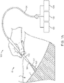
- FIG. 1A shows apparatus 100 comprising a handheld device, which may comprise a shaft 102 having a distal end with a nozzle 104 oriented to deliver a pressurized fluid in an axial stream water jet 101 with cavitation 103 as disclosed herein.
- the jet and tissue T can be immersed in a liquid L such as saline or another liquid to provide shedding pulses with cavitation as disclosed herein, for example.
- the liquid can be provided over the tissue with a gas G such as air above the liquid.
- the tissue may comprise an internal tissue covered with the liquid, for example. Water or other fluid is delivered under pressure from the nozzle.
- the handheld device 100 is capable of delivering an axial water jet or other pressurized fluid stream and is useful for the manual cutting of tissue or bone, for example.
- the handheld device 100 is connected to a pressurized fluid source 120, a fluid flow monitor 122, and control circuitry 124, typically by a connecting cord 126.
- the fluid flow monitor 122 may comprise a pressure monitor for example.
- the user can thus control the fluid pressure, movement of the nozzle (velocity, direction, limits, etc.) and other aspects of the treatment protocol in addition to the axial and rotational movement parameters using the control circuitry.
- the nozzle 104 will be adjustable in order to adjust the width and focus of the fluid stream FS in order to allow further flexibility for the treatment.
- the hand held shaft can be manipulated much as a scalpel.
- the nozzle can be mounted on a computer controlled positioning system such as a rotating, translating and oscillating probe, or a robotic arm, and combinations thereof.
- the pressurized pump comprises a high pressure pump such as a piston pump, for example.
- the control circuitry can be coupled to the pressure monitor 122, so as to provide a controlled flow rate.
- the controlled flow rate, in combination with the nozzle can provide a cavitation flame at distance, in order to incise tissue as disclosed herein.
- Figure 1B shows an apparatus 100 comprising computer controlled device suitable for treating tissue T in accordance with embodiments.
- Apparatus 100 may comprise a linkage 130 coupled to the treatment probe in order to treat tissue in response to computer commands.
- the linkage may comprise a linkage capable of translation, or capable of a rotating, oscillating and translating, and combinations thereof, for example.
- the linkage can be coupled to the processor 132 and may be guided under user control, for example.
- the embodiments disclosed herein are suitable for combination with many devices to remove tissue, such as computer controlled image guided treatment apparatus referenced elsewhere herein.
- FIG. 1C shows a nozzle 104 for treating tissue in accordance with embodiments.
- the nozzle can be configured in one or more of many ways as described herein, and is suitable for combination with flow rates in order to provide tissue removal with hemostasis as described herein.
- a flow rate through the nozzle and the configuration of the nozzle provide a maximum tissue removal distance.
- the jet 101 from the nozzle may comprise a selective tissue removal region 105 and a non-selective tissue removal region 107.
- the selective tissue removal region 105 of the jet can selectively remove tissue at rates in response to collagen of the tissue. For example, collagenous tissue such as blood vessel walls can be removed more quickly than tissue with less collagen such as granular tissue.
- the non-selective tissue removal region 107 of the jet can remove tissue having different amounts of collagen as substantially similar rates. For example, collagenous tissue such as blood vessel walls can be removed at rates substantially similar to tissue with less collagen such as granular tissue.
- a threshold transition zone 109 can be located between the selective tissue removal region and the non-selective tissue removal region.
- the nozzle can be mounted on a carrier 382 comprising a fluid delivery element and design considerations of the fluid delivery element.
- the carrier 382 can be provided on a rotating, translating and oscillating probe, for example.
- the jet orifice 111 design of the fluid delivery element can be configured in one or more of many ways as described herein, so as to provide a plurality of shedding pulses. Fluid jet ablation characteristics can be varied by varying the jet orifice geometry. For example cone angle 113 variation can result in an increase or decrease in cavitation 103 occurring at the nozzle exit.
- the jet orifice design may comprise a cone at one or more of the entrance or the exit of the orifice 111. The cone angle can vary from 0 to 180 degrees, for example.
- the jet nozzle profile also influences the degree of fluid acceleration and amount of cavitation. For example, a sharp edged orifice can induce a higher jet velocity at exit from the vena cava effect, with correspondingly greater amounts of cavitation 103 in the jet far field.
- the orifice diameter 115 and orifice length 117 variation can result in a variation in nozzle back pressure and exit speed of the fluid stream.
- the resulting cavitation region varies with each of these parameters.
- the cavitation region may comprise a cloud of cavitation bubbles generated by the nozzle.
- the depth of tissue penetration can be determined and controlled as described herein.
- the cavitation region can be visualized with ultrasound imaging or optical imaging in combinations thereof.
- the cavitation region corresponds to a region where bubbles are formed, which allows the entrainment region to be visualized and can be referred to as a fluid flame.
- the cool cutting of the cavitation region can allow for tissue removal with minimal tissue damage.
- the cone angles within a range from about 40 degrees to about 80 degrees.
- a ratio of the orifice length to the inner diameter of the orifice can be within a range from about 1 to 10, for example, within a range from about 4 to 7.
- a person of ordinary skill in the art can design a jet orifice to treat tissue as described herein based on the teachings provided herein.
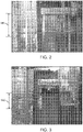
- Figure 2 shows an ablative flame visible to the human eye, in accordance with embodiments.
- Figure 3 shows a high speed image of the ablative flame as in Figure 2 .
- the image was taken at a speed of about 1/400 of a second.
- the data of Figures 2 and 3 show that the ablative flame comprises a plurality of white clouds generated with the ablative stream when released from the nozzle.
- Work in relation to embodiments has shown that the cavitating cloud can shed from the jet at a characteristic shedding frequency.
- a length 992 of each cloud is related to the shedding frequency and the velocity of the cloud.
- the relatively cool ablative flame of the jet comprises a length 990 corresponding to the cutting length of the jet which can be adjusted to cut tissue to controlled depth as described herein.
- nozzle of the jet is placed at least about a quarter of the length 992 of a shed cloud in an non-cutting configuration as shown in Figure 3 , in order to allow the shedding cloud to substantially form prior to the cloud striking tissue.
- This divergence of the shed cloud to a larger cross sectional size can also provide improved tissue removal as the cloud can be distributed to a larger region of tissue and provide improved overlap among the pulses of the jet.
- the highly turbulent and aggressive region corresponding to the white cloud of the image contributes substantially to the ablation of tissue as described herein.
- the white cloud comprises a plurality of cavitation regions.
- the small cavitations may comprise cavitation vortices.
- the cavitation vortices merge with one another, forming large discrete cavitation structures that appear in the high speed images as cavitation clouds.
- These cavitation clouds provide effective ablation when interacting with tissue. Without being bound by any particular theory, it is believed that the cavitation clouds striking tissue cause substantial erosion of tissue related to the cavitations in combination with the high velocity fluid that defines the cavitation clouds striking tissue.
- the nozzle and pressure as described herein can be configured to provide the pulsatile clouds, for example with control of the angle of the nozzle, by a person of ordinary skill on the art based on the teachings provided herein.
- the nozzle of the fluid delivery element comprises a cavitating jet in order to improve ablation of tissue.
- the fluid delivery element nozzle and pressure can be arranged to provide a shedding frequency suitable for removal of tissue.
- the fluid delivery element can be located on the probe at a distance from the tissue as described herein in order to provide improved tissue resection.
- the "white cloud” of "flame” comprises an "entrainment” region where surrounding water is drawn in or “entrained” into the jet.
- the entrainment of fluid can be related to the shedding frequency.
- the shedding frequency and size of the cloud shed from the jet can be used to provide tissue ablation in accordance with embodiments.
- the shedding frequency can be combined with the angular sweep rate of the probe around the longitudinal axis to provide overlap of the locations where each cloud interacts with the tissue.
- the shedding pulses as described herein can be beneficially combined with the scanning of the jet as described herein.
- FIG. 4 shows a plurality of shedding pulses 995 and sweeping of the ablative jet to provide smooth and controlled tissue erosion at a plurality of overlapping locations 997 in accordance with embodiments.
- This shedding frequency can be substantially faster than the pump frequency, when a pump is used, such that a plurality of shedding clouds are provided for each pulse of the pulsatile pump.
- the sweep rate of the probe can be related to shedding frequency to provide improved tissue removal, for example with the shedding clouds configured to provide overlapping pulses.
- the system comprises a pump having a frequency less than a frequency of the shedding pulses, in order to provide a plurality of shedding pulses for each pulse of the pump.
- the pump can have a pulse rate of at least about 50 Hz, for example within a range of about 50 Hz to about 200 Hz, and the shedding pulses comprise a frequency of at least about 500 Hz, for example within a range from about 1 kHz to about 10 kHz.
- pulses of a pump are illustrated, similar scanning of pulsed clouds can be provided with a continuous flow pump.
- the nozzle can be configured in one or more of many ways, in many embodiments the nozzle comprises a Strouhal number (hereinafter "St") within a range from about 0.02 to about 0.3, for example within a range from about 0.10 to about 0.25, and in many embodiments within a range from about 0.14 to about 0.2.
- St Strouhal number
- Fshed the shedding frequency
- W the width or diameter of the cavitating jet
- U the velocity of the jet at the exit.
- the nozzle configurations providing plurality of shedding clouds are suitable for use with one or more of the treatment probes as described herein.
- Cavitation is a phenomenon that occurs when a high pressure waterjet shoots through a nozzle into a liquid medium. Localized vapor pockets form as nuclei containing minute amounts of vapor and/or gas destabilize as they are subjected to drops in pressure rather than the commonly known method of addition of heat.
- a cavitation number ⁇ exists above which cavitation does not occur and below which cavitation will be present with increased cavitating region size.
- Several smaller pockets can combine to form a larger vapor cavity.
- the momentum of the waterjet carries the vapor cloud further away from the nozzle into surrounding medium, viscous forces cause the jet velocity to drop and there is a corresponding rise in pressure. This rise causes the vapor cavity to collapse, resulting in a pressure pulse which further accelerates nearby water and causes localized microjets to form.
- Both the liquid microjets and pressure pulse can exceed the damage threshold energy of a material and cause erosion. Due to the rapid loss in velocity as the jet moves away from the nozzle, beyond a given distance the kinetic energy of the stream no longer exceeds the threshold energy and pressure waves and microjets from collapsed cavitation clouds becomes the primary modality for erosion.
- cavitation is dependent on local changes in pressure only, making it an isothermal phenomenon, meaning no thermal fluctuations are expected.
- Experimentally as the vapor cavitation grows in size, latent heat is drawn from the surrounding liquid, and a very small drop in temperature ( ⁇ 0.35° C) can be observed.
- a very small drop in temperature ⁇ 0.35° C
- the process is not entirely isothermal, the almost negligible change in temperature is why waterjet cutting is useful for machining sensitive parts that demand no heat-affected zones.
- pressure pulse and microjet erosion becoming the primary modality of material removal is the limited erosion radius. Since cavitation occurs due to the pressure differential of the waterjet relative to the ambient liquid pressure, vapor cavities can only exist up to a maximum distance before the cavity collapses as the jet slows down and the pressure comes to equilibrium with the surrounding liquid. As a result, submerged waterjet cutting becomes substantially self-limiting due to the range of pressure pulses and microjets before they dissipate and is a very safe and high precision tool to cut with. In alternative embodiments, a gaseous waterjet will have high kinetic energy levels that exceed the threshold energy at much longer distances since there are relatively minimal forces acting on the jet to slow it down.
- Figure 5 shows maximum tissue penetration depth of cutting and flow rate through a nozzle in accordance with embodiments.
- the maximum penetration depth corresponds substantially to the length of the cavitation bubbles of the jet comprising the "cold" aquablation flame.
- the maximum tissue penetration depth of ablation corresponds directly to the flow rate and in many embodiments is linearly related to the flow rate.
- the flame with cavitations is shown with 10 flow settings corresponding to flow rates within a range from about 50 ml/min to about 250 ml/min with a nozzle and rotating probe as described herein.
- the maximum penetration depth ranges from about 4 mm at 50 ml/min to about 20 mm at 250 ml/min.
- the inset of Figure 5 shows cut potato as a model of prostate BPH, in accordance with embodiments.
- the maximum penetration depth of potato corresponds closely to the maximum cut depth of BPH.
- the potato is shown cut with 6 flow settings corresponding to flow rates within a range from about 50 ml/min to about 250 ml/min with a nozzle and rotating probe as described herein.
- the maximum penetration depth ranges from about 4 mm at 50 ml/min to about 20 mm at 250 ml/min, consistent with the images of the cavitations of the jet comprising the cool "flame" as described herein.
- the cavitation cloud growth and length comprises a function of flow rate, which is proportional to the injection pressure and vice versa, for an appropriately configured nozzle as described herein. As the pressure increases, the maximum erosive radius appears to increase linearly, which is shown as the maximum penetration depth of Figure 5 .
- High velocity cavitating jets can be created by using a known high pressure pump to force the water through a nozzle in either a continuous or pulsatile flow.
- the cavitation phenomenon will be pulsatile due to the unsteady nature of vapor cavities and the cavity formation will be pulsatile even in a continuous flow jet as described herein.
- nozzle geometry is configured to provide the flow dynamics and cavitation process as described herein.
- the nozzle is configured to inhibit tight constriction at the waterjet exit, which can be related cavitation can occur inside the nozzle itself.
- the sharp corners cause the water to separate from the wall and converge towards the nozzle centerline, further constricting the waterjet pathway while simultaneously reducing frictional effects caused by the nozzle wall. This results in an increased velocity along with the corresponding pressure drop and the vapor cavities formation. Vapor cavity formation will impact the overall flow dynamics as their eventual collapse results in turbulence and can affect erosion depth.
- a person of ordinary skill in the art can conduct experiments to determine appropriate nozzle geometry and flow rate to provide tissue removal as described herein without undue experimentation.
- Submerged waterjet cutting as described herein has the capability to take advantage of the cavitation phenomenon to treat patients with Benign Prostatic Hyperplasia (BPH).
- BPH Benign Prostatic Hyperplasia
- the jet removes the excess soft tissue growth seen in BPH through the pressure pulses and microjets caused by collapsed vapor cavities.
- the waterjet direction can be manipulated by changing the location and orientation of the devices nozzle in one or more of many ways. For example, by one or more of translating the nozzle along the anterior-posterior direction or by rotating the nozzle up to an angle such as 180 degrees, for example, and combinations thereof. As the handpiece probe may sit on the anterior side of the prostate, a rotation angle can be used for ablating the tissue obstruction.
- the depth of material can be controlled by configuring the pressure as well as nozzle geometry.
- a greater injection pressure can result in a faster exit velocity.
- the nozzle geometry can further increase the velocity depending on the constriction and will affect the degree of pressure drop as the waterjet exits through the Venturi effect. These factors can result in longer distances the cavitation clouds can grow to and travel before collapsing and releasing pressure pulses and microjets.
- the nozzle geometry and pressure settings of the Aquablation system have been optimized to give the user precise control and ensure the cavitating jet removes only the desired benign tissue growth.
- the images provided herein show the how tissue erosion depth is a function of pressure, in accordance with embodiments.
- the images show the smaller cavitation cloud length and corresponding tissue resection depth for a lower injection pressure as compared with other images.
- Aquablation as described herein is capable of removing the excess tissue growth, e.g. BPH, with substantial removal and damage of arteries and veins and inhibited bleeding.
- the jet is positioned to provide cavitation energy above the threshold of both growth tissue such as BPH and collagenous tissue such as blood vessels, with decreased bleeding.
- the pressure pulses and microjets provided by cavitation exceed the threshold energy required to erode the soft tissue growth and the other structures like vessels which have a much higher threshold energy.
- Vapor cavity formation may benefit from a minute nucleus of air already present in the blood stream, for example. Cavitation can result in the growth of the nucleus without any additional air being introduced into the system. Furthermore, the cavity will collapse once the local jet pressure exceeds the vapor pressure, such that the air pockets may reduce back to their original nucleus size.
- embolus formation is inhibited as cavitation depends on and can be limited to micro amounts of air native to the saline solution surrounding the urethra, and the vapor cavities quickly dissipate as the jet pressure begins to rise.
- Figure 6 shows maximum tissue penetration 110 versus flow rate similar to Figure 5 in accordance with embodiments.
- the nozzle positions in relation to tissue can be used to determine the tissue incision as substantially abrasive, or substantially selective, and combinations thereof, for example.
- Selective tissue removal 105 of substantially non-collagenous tissue such as BPH at rates substantially faster than collagenous tissue such as vessels can be provided at distances beyond a transition threshold 109.
- Highly abrasive substantially non-selective removal 107 is provided at distances from tissue less than the threshold distance 109, in accordance with the apparatus of the present invention.
- the transition threshold may comprise a substantially linear function with an offset.
- the slope can be somewhat steeper than the transition threshold with an offset.
- the threshold transition from selective tissue removal to highly abrasive substantially non-selective tissue removal may comprise one or more of many functions of flow rate and distance from the nozzle.
- the threshold transition may comprise one or more of a linear function, a polynomial function, or an empirically determined transform function, and combinations thereof, for example.
- a person of ordinary skill in the art can determine the distances for selective removal and substantially abrasive tissue removal in accordance with the teachings as described herein without undue experimentation.
- Figure 7 shows a threshold 109 transition from selective removal 105 to abrasive removal 107 comprising a slope similar to the slope of the maximum penetration depth 110, with an offset in accordance with embodiments.
- the offset can be related to the fluid jet parameters as described herein.
- Figures 8A and 8B show selective tissue removal.
- the tissue can be positioned at a distance greater than the transition threshold in order to provide selective tissue removal.
- Figure 8A shows tissue T prior to selective removal.
- the soft granular tissue GT can be substantially removed with inhibited removal of collagenous tissue CT such as blood vessels V, as shown in Figure 8B .
- Work in relation to embodiments suggests that the shedding pulses as described herein can affect the endothelium, which may contribute to clotting and decreased bleeding in accordance with some embodiments.
- Figure 9A and 9B show highly abrasive tissue removal in accordance with with an apparatus of the present invention.
- Figure 9A shows tissue T prior to removal.
- Figure 9B shows the tissue subsequent to removal.
- the collagenous tissue CT comprising the blood vessel V can be removed at substantially the same rate as the substantially less collagenous granular tissue GT such as BPH, as shown with the removal profile RP.
- the highly abrasive tissue removal is provided with the nozzle positioned at a distance less than the transition threshold for a provided flow rate as described herein.
- the endothelial cell lining E of the blood vessels V can be affected so as to provide one or more of micro clotting; clotting; emboli or micro-emboli, and one or more biological responses as described herein.
- induced micro-clotting C can substantially occlude the blood vessels and capillaries of the occluded tissue.
- FIG 10 shows a collapsed vessel wall CW, in accordance with embodiments.
- the collapsed vessel wall CW can be generated with the highly abrasive cavitation as described herein.
- the cavitation and jet can induce collapse of the vessel wall W.
- the collapse of the vessel wall can inhibit blood flow through the incised end of the vessel V.
- the vessel wall can inhibit blood flow in one or more of many ways in response to the cavitation.
- the ends of the cut vessel may comprise strands of cut collagen that provide an increased surface area to provide interaction with platelets and blood cells to induce clotting.
- the frayed ends of the blood vessel can extend inwardly toward to the end of the severed blood vessel so as to inhibit bleeding, for example.
- the endothelium of the blood vessel can be affected so as to provide clotting within the vessel.
- FIG 11A shows a water jet flame 101 removing tissue with shedding pulses in accordance with embodiments.
- the water shedding pulses induce a shear wave 121 along the lumen of the blood vessel V.
- the plurality shedding pulses as described herein can provide oscillations of the liquid within the blood vessel.
- the oscillations provide a shear wave propagating transverse to the vessel wall W at a distance from the tissue region where the flame strikes. This shear wave can induce coagulation at a distance from the region contacted with the cavitation 103 as shown in Figure 11A .
- the disruption of the vessel at a distance from the jet may comprise one or more of shearing of the endothelial layer E of the vessel, lysis of a plurality of endothelial cells at a distance, shearing of a plurality of red blood cells RBC, lysis of the plurality of red blood cells shearing of platelets, partial removal of endothelial cells from the vascular wall, complete removal of endothelial cells, generation of fibrin or clotting, and combinations thereof, for example.
- the plurality of shedding pulses comprises at least about two shedding pulses for each pulse of the pump, for example within a range from about 5 to about 20 shedding pulses per pulse of the pump.
- the shedding pulses may comprise highly abrasive shedding pulses as described herein, or selective shedding pulses as described herein, and combinations thereof for example.
- the substantially abrasive zone of the jet comprising shedding pulses can be effective in providing the increased clotting as described herein.
- the selective tissue removal zone can be effective in providing the increased clotting as described herein.
- Figure 11B shows disruption 123 to a blood vessel V in accordance with embodiments.
- the disruption of the endothelium E and corresponding clotting C as described herein are shown at a distance 125 from the tissue removal profile RP.
Description
- The field of the present invention is related to the treatment of tissue, and more specifically to the surgical treatment of an organ such as the prostate.
- Prior methods and apparatus of incising tissue of subjects such as patients can result in less than ideal results in at least some instances. For example, prior methods of prostate surgery can result in longer healing time and less than ideal outcomes in at least some instances. In at least some instances, prior methods and apparatus of tissue resection can result in more bleeding than would be ideal. Also, the prior methods and apparatus of cutting tissue can provide less accurate cuts than would be ideal. Although electrocautery and laser coagulation have been proposed as a potential solution to bleeding, treatment with electrocautery or laser coagulation may result in an additional step to removal of tissue, and the control of bleeding can be less than ideal. Also, the heat associated with electrocautery may result in less than ideal results in at least some instances.
- With prior surgical procedures, the recovery time of the patient can be related to the manner in which tissue is removed, and it would be helpful to provide surgical procedures with decreased recovery times. Also, tissue drainage can be somewhat greater than would be ideal, and can be related to the manner in which tissue is incised. In at least some instances, patients may benefit from a blood transfusion following surgery, and it would be better if fewer blood transfusions were required subsequent to surgery.
- Although removal of tissue with water jets can result in successful removal of tissue, work in relation to embodiments suggests that further improvements may be helpful. For example, the prior methods and apparatus of cutting tissue with a water jet can result in somewhat less accurate cutting and potentially more bleeding than would be ideal in at least some instances. Although prior methods of tissue cutting can cut ablate tissue with fluid jet technology with the decreased transfer of heat to the tissue, work in relation to embodiments suggests that in at least some instances prior water jet cutting can result in amounts of bleeding that can be somewhat greater than would be ideal.
- In light of the above, it would be helpful to provide improved apparatus for tissue treatment such as surgery. Ideally such apparatus would provide improved resection of tissue with decreased bleeding and improved outcomes.
-
WO 2013/130895 describes a system to treat a patient comprising a user interface that allows a physician to view an image of tissue to be treated in order to develop a treatment plan to resect tissue with a predefined removal profile. The image may comprise a plurality of images, and the planned treatment is shown on the images. The treatment probe may comprise an anchor, and the image shown on the screen may have a reference image marker shown on the screen corresponding to the anchor. The planned tissue removal profile can be displayed and scaled to the image of the target tissue of an organ such as the prostate, and the physician can adjust the treatment profile based on the scaled images to provide a treatment profile in three dimensions. The images shown on the display may comprise segmented images of the patient with treatment plan overlaid on the images. -
WO 2015/035249 which published after the priority date of the present application describes a fluid stream directed towards tissue to generate a plurality of shedding clouds. The fluid stream can be scanned such that the plurality of shedding clouds arrive a different overlapping locations. Each of the plurality of shedding clouds can remove a portion of the tissue. In many embodiments, an apparatus to ablate tissue comprises a source of pressurized fluid, and a nozzle coupled to the source of pressurized fluid to release a fluid stream, in which the fluid stream generates a plurality of shedding clouds. -
US 4 474 251 describes a process and apparatus for enhancing the erosive intensity of a high velocity liquid jet when the jet is impacted against a surface for cutting, cleaning, drilling or otherwise acting on the surface. A preferred method comprises the steps of forming a high velocity liquid jet, oscillating the velocity of the jet at a preferred Strouhal number, and impinging the pulsed jet against a solid surface to be eroded. Typically the liquid jet is pulsed by oscillating the velocity of the jet mechanically or by hydrodynamic and acoustic interactions. The embodiments may be applied to enhance cavitation erosion in a cavitating liquid jet, or to modulate the velocity of a liquid jet exiting in a gas, causing it to form into discrete slugs, thereby producing an intermittent percussive effect. - The present invention is set out in the appended claims. Disclosed herein are methods, not forming part of the claimed invention, and apparatus of cutting tissue with water jet. In many embodiments, the apparatus is configured to provide hemostasis with tissue removal in order to inhibit one or more of blood loss or tissue drainage. In many embodiments, a nozzle releases a liquid jet in a liquid medium in order to provide cavitation and a plurality of shedding pulses. The cavitation and the plurality of shedding pulses can affect vascular tissue in order to promote clotting in order to inhibit bleeding. In many embodiments, vessels of the vascular tissue are affected at a distance from a region where cavitation of the water jet contacts the tissue. In many embodiments, the cavitation and plurality of shedding pules are related to a pulsatile shear wave propagating along the blood vessel that is related to clot promoting changes of the blood vessel. In many embodiments, the nozzle is placed at a distance from a tissue removal profile in order to provide substantially abrasive tissue removal, in which vascular tissue and non-vascular tissue with less collagen are removed at similar rates. In non-claimed embodiments, the nozzle can be placed at a distance from a tissue removal profile in order to provide substantially selective tissue removal, in which vascular tissue and non-vascular tissue with less collagen are removed at substantially different rates. In many embodiments, an endothelial cell lining of the vessel wall is affected in order to promote blood clotting within the vessel.
- In many embodiments wherein bleeding of the vascular tissue is inhibited with one or more of: induced thrombosis in capillaries and arterioles related to endothelial injury, shear stress and reduction in blood flow; adhesion and aggregation of platelets; deposition of fibrin; deposition of fibrin related to obstructive vessel clotting; fluid pressure in an affected zone; fluid pressure in an affected zone at a distance from a removal profile; inhibited blood the affected vessels; partial collapse of the affected blood vessels; full collapse of the affected blood vessels; and combinations thereof.
- A better understanding of the features and advantages of the present disclosure will be obtained by reference to the following detailed description that sets forth illustrative embodiments, and the accompanying drawings of which:
-
Figure 1A is a schematic illustration of a device suitable for treating tissue in accordance with embodiments; -
Figure 1B shows a computer controlled device suitable for treating tissue in accordance with embodiments; -
Figure 1C shows a nozzle for treating tissue in accordance with embodiments; -
Figure 2 shows an ablative flame visible to the human eye, in accordance with embodiments. -
Figure 3 shows a high speed image of the ablative flame as inFigure 2 taken at a speed of about 1/400 of a second, in accordance with embodiments; -
Figure 4 shows a plurality ofshedding pulses 995 and sweeping of the ablative jet to provide smooth and controlled tissue erosion at a plurality of overlappinglocations 997 in accordance with embodiments; -
Figure 5 shows maximum tissue penetration depth of cutting and flow rate through a nozzle in accordance with embodiments; -
Figure 6 shows maximum tissue penetration versus flow rate similar toFigure 5 in accordance with embodiments; -
Figure 7 shows a threshold transition from selective removal to abrasive removal comprising a slope similar to the slope of the maximum penetration depth, with an offset in accordance with embodiments; -
Figures 8A and 8B show selective tissue removal, in accordance with non-claimed embodiments; -
Figure 9A and 9B show highly abrasive tissue removal in accordance with the present inventive apparatus; -
Figure 10 shows a collapsed vessel wall, in accordance with embodiments; -
Figure 11A shows a water jet flame removing tissue with shedding pulses in accordance with embodiments; and -
Figure 11B shows disruption to a blood vessel in accordance with embodiments. - Although the detailed description contains many specifics, these should not be construed as limiting the scope of the invention claimed but merely as illustrating different examples and aspects of the invention. It should be appreciated that the scope of the invention includes other embodiments not discussed in detail above. Various other modifications, changes and variations which will be apparent to those skilled in the art may be made in the arrangement, operation and details of the apparatus disclosed herein without departing from the scope of the invention as claimed.
- As used herein the term "AquaBeam" encompasses a liquid jet provided in a liquid to provide cavitation to tissue.
- The fluid jet tissue ablation (hereinafter "Aquablation") and methods and apparatus for providing hemostasis with tissue cutting as disclosed herein are well suited for combination with many prior surgical procedures and apparatus. In many embodiments, improved hemostasis is provided, which is related to the tissue incision with the jet. In many embodiments, the jet comprises jet in a liquid medium which induces cavitation of the jet, which can be referred to as a cool flame, which can be related to the substantially mechanical shear stress interactions between the high-velocity fluid jet and the vessels in contact with the jet. In many embodiments, the jet comprises sufficient energy above the threshold of cavitation such that tissue removal of the jet is substantially insensitive to the type of tissue and amount of collagen of the tissue and can cut vascular and granular tissue at similar rates. The mechanical contact of tissue with the jet and corresponding shear can induce micro-thrombosis in capillaries and arterioles can provide improved coagulation and corresponding hemostasis. In many embodiments, the endothelial cells can be affected so as to facilitate the release of blood clotting factors. The effect to the endothelial cells as described herein can occur at a distance from the site where the cavitations of the jet and liquid medium strike the tissue in order to provide improved hemostasis. In many embodiments, the substantially mechanical shear stress can provide damage to the endothelial cells and provide a reduction in blood flow, and may facilitate and enhance the adhesion and aggregation of platelets and deposition of fibrin, so as to provide obstructive vessel clotting.
- In many embodiments, shear stress supplied by the jet is sufficient to induce platelet aggregation independent of complement activation. The platelet aggregation independent of complement activation can occur in a manner similar to areas of high hemodynamic shear, such as in arterial stenosis as described previously. See Blood. Activation-independent platelet adhesion and aggregation under elevated shear stress. ZM Rugerri et al. By providing water jet shear stress directly to affected vessels, for a sufficient period of time platelet aggregation may achieve initial hemostasis, allowing the coagulation cascade to thrombose the affected vessels and achieve lasting hemostasis. As shear increases, the time to achieve hemostatic platelet aggregation may decrease. The Aquablation as described herein can be tuned to improve hemostasis by controlling pump power (and with it fluid velocity, and shear stress magnitude) and rate of translation of the water jet. In many embodiments, higher pumping power and slower translation of the jet are pro-hemostatic. Alternatively or in combination, the relative contribution of various hemostatic factors (local pressure gradients, shear modulated hemostasis, cavitation induced thrombosis) can vary depending on the position of the vessel relative to the jet (for a specific pump power) position, as related to the evolution of the flame with distance traveled from the jet nozzle exit.
- While the vessel clotting can be provided in one or more of many ways, in many embodiments the fluid pressure in the affected zone during tissue treatment with the water jet may rapidly inhibit and substantially decrease blood from exiting the affected vessels. In many embodiments, the hemostasis as described herein is related to the partial or full collapse of the affected vessels. In many embodiments, the substantially mechanical shear stress provided with the cavitations can provides fluid jet tissue resection and ablation of tissue and also to heat-free tissue coagulation.
-
FIG. 1A showsapparatus 100 comprising a handheld device, which may comprise ashaft 102 having a distal end with anozzle 104 oriented to deliver a pressurized fluid in an axialstream water jet 101 withcavitation 103 as disclosed herein. The jet and tissue T can be immersed in a liquid L such as saline or another liquid to provide shedding pulses with cavitation as disclosed herein, for example. The liquid can be provided over the tissue with a gas G such as air above the liquid. Alternatively or in combination, the tissue may comprise an internal tissue covered with the liquid, for example. Water or other fluid is delivered under pressure from the nozzle. Thehandheld device 100 is capable of delivering an axial water jet or other pressurized fluid stream and is useful for the manual cutting of tissue or bone, for example. Thehandheld device 100 is connected to a pressurizedfluid source 120, a fluid flow monitor 122, andcontrol circuitry 124, typically by a connectingcord 126. The fluid flow monitor 122 may comprise a pressure monitor for example. The user can thus control the fluid pressure, movement of the nozzle (velocity, direction, limits, etc.) and other aspects of the treatment protocol in addition to the axial and rotational movement parameters using the control circuitry. Optionally, although not illustrated, thenozzle 104 will be adjustable in order to adjust the width and focus of the fluid stream FS in order to allow further flexibility for the treatment. When used for cutting tissue, the hand held shaft can be manipulated much as a scalpel. Alternatively, the nozzle can be mounted on a computer controlled positioning system such as a rotating, translating and oscillating probe, or a robotic arm, and combinations thereof. - In many embodiments, the pressurized pump comprises a high pressure pump such as a piston pump, for example. The control circuitry can be coupled to the pressure monitor 122, so as to provide a controlled flow rate. The controlled flow rate, in combination with the nozzle can provide a cavitation flame at distance, in order to incise tissue as disclosed herein.
-
Figure 1B shows anapparatus 100 comprising computer controlled device suitable for treating tissue T in accordance with embodiments.Apparatus 100 may comprise alinkage 130 coupled to the treatment probe in order to treat tissue in response to computer commands. The linkage may comprise a linkage capable of translation, or capable of a rotating, oscillating and translating, and combinations thereof, for example. The linkage can be coupled to theprocessor 132 and may be guided under user control, for example. The embodiments disclosed herein are suitable for combination with many devices to remove tissue, such as computer controlled image guided treatment apparatus referenced elsewhere herein. -
Figure 1C shows anozzle 104 for treating tissue in accordance with embodiments. The nozzle can be configured in one or more of many ways as described herein, and is suitable for combination with flow rates in order to provide tissue removal with hemostasis as described herein. In many embodiments, a flow rate through the nozzle and the configuration of the nozzle provide a maximum tissue removal distance. Thejet 101 from the nozzle may comprise a selectivetissue removal region 105 and a non-selectivetissue removal region 107. The selectivetissue removal region 105 of the jet can selectively remove tissue at rates in response to collagen of the tissue. For example, collagenous tissue such as blood vessel walls can be removed more quickly than tissue with less collagen such as granular tissue. The non-selectivetissue removal region 107 of the jet can remove tissue having different amounts of collagen as substantially similar rates. For example, collagenous tissue such as blood vessel walls can be removed at rates substantially similar to tissue with less collagen such as granular tissue. Athreshold transition zone 109 can be located between the selective tissue removal region and the non-selective tissue removal region. - The nozzle can be mounted on a
carrier 382 comprising a fluid delivery element and design considerations of the fluid delivery element. Thecarrier 382 can be provided on a rotating, translating and oscillating probe, for example. The jet orifice 111 design of the fluid delivery element can be configured in one or more of many ways as described herein, so as to provide a plurality of shedding pulses. Fluid jet ablation characteristics can be varied by varying the jet orifice geometry. Forexample cone angle 113 variation can result in an increase or decrease incavitation 103 occurring at the nozzle exit. The jet orifice design may comprise a cone at one or more of the entrance or the exit of the orifice 111. The cone angle can vary from 0 to 180 degrees, for example. - In many embodiments, the jet nozzle profile also influences the degree of fluid acceleration and amount of cavitation. For example, a sharp edged orifice can induce a higher jet velocity at exit from the vena cava effect, with correspondingly greater amounts of
cavitation 103 in the jet far field. - The orifice diameter 115 and
orifice length 117 variation can result in a variation in nozzle back pressure and exit speed of the fluid stream. The resulting cavitation region varies with each of these parameters. The cavitation region may comprise a cloud of cavitation bubbles generated by the nozzle. The depth of tissue penetration can be determined and controlled as described herein. In many embodiments the cavitation region can be visualized with ultrasound imaging or optical imaging in combinations thereof. The cavitation region corresponds to a region where bubbles are formed, which allows the entrainment region to be visualized and can be referred to as a fluid flame. The cool cutting of the cavitation region can allow for tissue removal with minimal tissue damage. In many embodiments the cone angles within a range from about 40 degrees to about 80 degrees. A ratio of the orifice length to the inner diameter of the orifice can be within a range from about 1 to 10, for example, within a range from about 4 to 7. A person of ordinary skill in the art can design a jet orifice to treat tissue as described herein based on the teachings provided herein. -
Figure 2 shows an ablative flame visible to the human eye, in accordance with embodiments. -
Figure 3 shows a high speed image of the ablative flame as inFigure 2 . The image was taken at a speed of about 1/400 of a second. - The data of
Figures 2 and 3 show that the ablative flame comprises a plurality of white clouds generated with the ablative stream when released from the nozzle. Work in relation to embodiments has shown that the cavitating cloud can shed from the jet at a characteristic shedding frequency. Alength 992 of each cloud is related to the shedding frequency and the velocity of the cloud. The relatively cool ablative flame of the jet comprises alength 990 corresponding to the cutting length of the jet which can be adjusted to cut tissue to controlled depth as described herein. In many embodiments, nozzle of the jet is placed at least about a quarter of thelength 992 of a shed cloud in an non-cutting configuration as shown inFigure 3 , in order to allow the shedding cloud to substantially form prior to the cloud striking tissue. This divergence of the shed cloud to a larger cross sectional size can also provide improved tissue removal as the cloud can be distributed to a larger region of tissue and provide improved overlap among the pulses of the jet. - In addition to the impact pressure of the jet, the highly turbulent and aggressive region corresponding to the white cloud of the image contributes substantially to the ablation of tissue as described herein. The white cloud comprises a plurality of cavitation regions. When pressurized liquid comprising water is injected into water, small cavitations are generated in areas of low pressure in the shear layer, near the nozzle exit. The small cavitations may comprise cavitation vortices. The cavitation vortices merge with one another, forming large discrete cavitation structures that appear in the high speed images as cavitation clouds. These cavitation clouds provide effective ablation when interacting with tissue. Without being bound by any particular theory, it is believed that the cavitation clouds striking tissue cause substantial erosion of tissue related to the cavitations in combination with the high velocity fluid that defines the cavitation clouds striking tissue.
- The nozzle and pressure as described herein can be configured to provide the pulsatile clouds, for example with control of the angle of the nozzle, by a person of ordinary skill on the art based on the teachings provided herein. In many embodiments, the nozzle of the fluid delivery element comprises a cavitating jet in order to improve ablation of tissue.
- The fluid delivery element nozzle and pressure can be arranged to provide a shedding frequency suitable for removal of tissue. The fluid delivery element can be located on the probe at a distance from the tissue as described herein in order to provide improved tissue resection.
- In many embodiments, the "white cloud" of "flame" comprises an "entrainment" region where surrounding water is drawn in or "entrained" into the jet. Work in relation to embodiments suggests that the entrainment of fluid can be related to the shedding frequency.
- The shedding frequency and size of the cloud shed from the jet can be used to provide tissue ablation in accordance with embodiments. The shedding frequency can be combined with the angular sweep rate of the probe around the longitudinal axis to provide overlap of the locations where each cloud interacts with the tissue.
- The shedding pulses as described herein can be beneficially combined with the scanning of the jet as described herein.
-
Figure 4 shows a plurality of sheddingpulses 995 and sweeping of the ablative jet to provide smooth and controlled tissue erosion at a plurality of overlappinglocations 997 in accordance with embodiments. This shedding frequency can be substantially faster than the pump frequency, when a pump is used, such that a plurality of shedding clouds are provided for each pulse of the pulsatile pump. The sweep rate of the probe can be related to shedding frequency to provide improved tissue removal, for example with the shedding clouds configured to provide overlapping pulses. - In many embodiments, the system comprises a pump having a frequency less than a frequency of the shedding pulses, in order to provide a plurality of shedding pulses for each pulse of the pump. The pump can have a pulse rate of at least about 50 Hz, for example within a range of about 50 Hz to about 200 Hz, and the shedding pulses comprise a frequency of at least about 500 Hz, for example within a range from about 1 kHz to about 10 kHz.
- Although pulses of a pump are illustrated, similar scanning of pulsed clouds can be provided with a continuous flow pump.
- While the nozzle can be configured in one or more of many ways, in many embodiments the nozzle comprises a Strouhal number (hereinafter "St") within a range from about 0.02 to about 0.3, for example within a range from about 0.10 to about 0.25, and in many embodiments within a range from about 0.14 to about 0.2.
- In many embodiments, the Strouhal number is defined by:

where Fshed is the shedding frequency, W is the width or diameter of the cavitating jet, and U is the velocity of the jet at the exit. A person of ordinary skill in the art can modify nozzles as described herein in order to obtain shedding frequencies suitable for combination in accordance with embodiments described herein, and experiments can be conducted to determine the cloud lengths and shedding frequencies suitable for tissue removal. - The nozzle configurations providing plurality of shedding clouds are suitable for use with one or more of the treatment probes as described herein.
- Cavitation is a phenomenon that occurs when a high pressure waterjet shoots through a nozzle into a liquid medium. Localized vapor pockets form as nuclei containing minute amounts of vapor and/or gas destabilize as they are subjected to drops in pressure rather than the commonly known method of addition of heat. Cavitation occurs when the local pressure drops below the vapor pressure, which occurs when the negative pressure coefficient (-Cp) is greater than cavitation number (σ), respectively governed by the equations below


where pref is the hydrostatic pressure at the nozzle depth, p is the local pressure at the jet, ρ is the fluid density, vref is the exit velocity of the waterjet at the nozzle, and pv is the vapor pressure. When a liquid flows through a constricted region, its velocity inreases to maintain continuity and there is a corresponding drop in pressure, known as the Venturi effect. Applying this to submerged waterjets, the velocity of water exiting through a nozzle is increased dramatically due to the constriction while the pressure of the jet stream is substantially reduced. When the pressure reduction is significant enough, it can drop below the vapor pressure, resulting in vapor cavity formation. - For a given flow dynamic, a cavitation number σ exists above which cavitation does not occur and below which cavitation will be present with increased cavitating region size. Several smaller pockets can combine to form a larger vapor cavity. As the momentum of the waterjet carries the vapor cloud further away from the nozzle into surrounding medium, viscous forces cause the jet velocity to drop and there is a corresponding rise in pressure. This rise causes the vapor cavity to collapse, resulting in a pressure pulse which further accelerates nearby water and causes localized microjets to form. Both the liquid microjets and pressure pulse can exceed the damage threshold energy of a material and cause erosion. Due to the rapid loss in velocity as the jet moves away from the nozzle, beyond a given distance the kinetic energy of the stream no longer exceeds the threshold energy and pressure waves and microjets from collapsed cavitation clouds becomes the primary modality for erosion.
- In many embodiments, cavitation is dependent on local changes in pressure only, making it an isothermal phenomenon, meaning no thermal fluctuations are expected. Experimentally, as the vapor cavitation grows in size, latent heat is drawn from the surrounding liquid, and a very small drop in temperature (~0.35° C) can be observed. Although in many embodiments, the process is not entirely isothermal, the almost negligible change in temperature is why waterjet cutting is useful for machining sensitive parts that demand no heat-affected zones.
- In many embodiments, pressure pulse and microjet erosion becoming the primary modality of material removal is the limited erosion radius. Since cavitation occurs due to the pressure differential of the waterjet relative to the ambient liquid pressure, vapor cavities can only exist up to a maximum distance before the cavity collapses as the jet slows down and the pressure comes to equilibrium with the surrounding liquid. As a result, submerged waterjet cutting becomes substantially self-limiting due to the range of pressure pulses and microjets before they dissipate and is a very safe and high precision tool to cut with. In alternative embodiments, a gaseous waterjet will have high kinetic energy levels that exceed the threshold energy at much longer distances since there are relatively minimal forces acting on the jet to slow it down.
-
Figure 5 shows maximum tissue penetration depth of cutting and flow rate through a nozzle in accordance with embodiments. The maximum penetration depth corresponds substantially to the length of the cavitation bubbles of the jet comprising the "cold" aquablation flame. The maximum tissue penetration depth of ablation corresponds directly to the flow rate and in many embodiments is linearly related to the flow rate. - The flame with cavitations is shown with 10 flow settings corresponding to flow rates within a range from about 50 ml/min to about 250 ml/min with a nozzle and rotating probe as described herein. The maximum penetration depth ranges from about 4 mm at 50 ml/min to about 20 mm at 250 ml/min.
- The inset of
Figure 5 shows cut potato as a model of prostate BPH, in accordance with embodiments. The maximum penetration depth of potato corresponds closely to the maximum cut depth of BPH. The potato is shown cut with 6 flow settings corresponding to flow rates within a range from about 50 ml/min to about 250 ml/min with a nozzle and rotating probe as described herein. The maximum penetration depth ranges from about 4 mm at 50 ml/min to about 20 mm at 250 ml/min, consistent with the images of the cavitations of the jet comprising the cool "flame" as described herein. - In many embodiments, the cavitation cloud growth and length comprises a function of flow rate, which is proportional to the injection pressure and vice versa, for an appropriately configured nozzle as described herein. As the pressure increases, the maximum erosive radius appears to increase linearly, which is shown as the maximum penetration depth of
Figure 5 . - High velocity cavitating jets can be created by using a known high pressure pump to force the water through a nozzle in either a continuous or pulsatile flow. Despite the flow type produced by a pump, the cavitation phenomenon will be pulsatile due to the unsteady nature of vapor cavities and the cavity formation will be pulsatile even in a continuous flow jet as described herein. Without being bound to a particular theory, it is believed that both pulsatile and continuous flow waterjets will result in equivalent amounts of material erosion over a given amount of time. In many embodiments, nozzle geometry is configured to provide the flow dynamics and cavitation process as described herein. In many embodiments, the nozzle is configured to inhibit tight constriction at the waterjet exit, which can be related cavitation can occur inside the nozzle itself. In many embodiments, the sharp corners cause the water to separate from the wall and converge towards the nozzle centerline, further constricting the waterjet pathway while simultaneously reducing frictional effects caused by the nozzle wall. This results in an increased velocity along with the corresponding pressure drop and the vapor cavities formation. Vapor cavity formation will impact the overall flow dynamics as their eventual collapse results in turbulence and can affect erosion depth. A person of ordinary skill in the art can conduct experiments to determine appropriate nozzle geometry and flow rate to provide tissue removal as described herein without undue experimentation.
- Submerged waterjet cutting as described herein has the capability to take advantage of the cavitation phenomenon to treat patients with Benign Prostatic Hyperplasia (BPH). The jet removes the excess soft tissue growth seen in BPH through the pressure pulses and microjets caused by collapsed vapor cavities. The waterjet direction can be manipulated by changing the location and orientation of the devices nozzle in one or more of many ways. For example, by one or more of translating the nozzle along the anterior-posterior direction or by rotating the nozzle up to an angle such as 180 degrees, for example, and combinations thereof. As the handpiece probe may sit on the anterior side of the prostate, a rotation angle can be used for ablating the tissue obstruction.
- As vapor cavity formation and its erosive strength is a function of both injection pressure and the flow dynamics, the depth of material can be controlled by configuring the pressure as well as nozzle geometry. A greater injection pressure can result in a faster exit velocity. As described herein, the nozzle geometry can further increase the velocity depending on the constriction and will affect the degree of pressure drop as the waterjet exits through the Venturi effect. These factors can result in longer distances the cavitation clouds can grow to and travel before collapsing and releasing pressure pulses and microjets. The nozzle geometry and pressure settings of the Aquablation system have been optimized to give the user precise control and ensure the cavitating jet removes only the desired benign tissue growth.
- The images provided herein show the how tissue erosion depth is a function of pressure, in accordance with embodiments. The images show the smaller cavitation cloud length and corresponding tissue resection depth for a lower injection pressure as compared with other images.
- In many embodiments, Aquablation as described herein is capable of removing the excess tissue growth, e.g. BPH, with substantial removal and damage of arteries and veins and inhibited bleeding. In many embodiments, the jet is positioned to provide cavitation energy above the threshold of both growth tissue such as BPH and collagenous tissue such as blood vessels, with decreased bleeding. The pressure pulses and microjets provided by cavitation exceed the threshold energy required to erode the soft tissue growth and the other structures like vessels which have a much higher threshold energy.
- In many embodiments, generation of harmful emboli are inhibited. Vapor cavity formation may benefit from a minute nucleus of air already present in the blood stream, for example. Cavitation can result in the growth of the nucleus without any additional air being introduced into the system. Furthermore, the cavity will collapse once the local jet pressure exceeds the vapor pressure, such that the air pockets may reduce back to their original nucleus size. In many embodiments, embolus formation is inhibited as cavitation depends on and can be limited to micro amounts of air native to the saline solution surrounding the urethra, and the vapor cavities quickly dissipate as the jet pressure begins to rise.
-
Figure 6 showsmaximum tissue penetration 110 versus flow rate similar toFigure 5 in accordance with embodiments. The nozzle positions in relation to tissue can be used to determine the tissue incision as substantially abrasive, or substantially selective, and combinations thereof, for example.Selective tissue removal 105 of substantially non-collagenous tissue such as BPH at rates substantially faster than collagenous tissue such as vessels can be provided at distances beyond atransition threshold 109. Highly abrasive substantiallynon-selective removal 107 is provided at distances from tissue less than thethreshold distance 109, in accordance with the apparatus of the present invention. The transition threshold may comprise a substantially linear function with an offset. For example, the slope can be somewhat steeper than the transition threshold with an offset. - The threshold transition from selective tissue removal to highly abrasive substantially non-selective tissue removal may comprise one or more of many functions of flow rate and distance from the nozzle. For example, the threshold transition may comprise one or more of a linear function, a polynomial function, or an empirically determined transform function, and combinations thereof, for example. A person of ordinary skill in the art can determine the distances for selective removal and substantially abrasive tissue removal in accordance with the teachings as described herein without undue experimentation.
-
Figure 7 shows athreshold 109 transition fromselective removal 105 toabrasive removal 107 comprising a slope similar to the slope of themaximum penetration depth 110, with an offset in accordance with embodiments. The offset can be related to the fluid jet parameters as described herein. -
Figures 8A and 8B show selective tissue removal. The tissue can be positioned at a distance greater than the transition threshold in order to provide selective tissue removal.Figure 8A shows tissue T prior to selective removal. The soft granular tissue GT can be substantially removed with inhibited removal of collagenous tissue CT such as blood vessels V, as shown inFigure 8B . Work in relation to embodiments suggests that the shedding pulses as described herein can affect the endothelium, which may contribute to clotting and decreased bleeding in accordance with some embodiments. -
Figure 9A and 9B show highly abrasive tissue removal in accordance with with an apparatus of the present invention.Figure 9A shows tissue T prior to removal.Figure 9B shows the tissue subsequent to removal. The collagenous tissue CT comprising the blood vessel V can be removed at substantially the same rate as the substantially less collagenous granular tissue GT such as BPH, as shown with the removal profile RP. The highly abrasive tissue removal is provided with the nozzle positioned at a distance less than the transition threshold for a provided flow rate as described herein. - In many embodiments, the endothelial cell lining E of the blood vessels V can be affected so as to provide one or more of micro clotting; clotting; emboli or micro-emboli, and one or more biological responses as described herein. In many embodiments, induced micro-clotting C can substantially occlude the blood vessels and capillaries of the occluded tissue.
-
Figure 10 shows a collapsed vessel wall CW, in accordance with embodiments. The collapsed vessel wall CW can be generated with the highly abrasive cavitation as described herein. In many embodiments, the cavitation and jet can induce collapse of the vessel wall W. The collapse of the vessel wall can inhibit blood flow through the incised end of the vessel V. - The vessel wall can inhibit blood flow in one or more of many ways in response to the cavitation. In many embodiments, the ends of the cut vessel may comprise strands of cut collagen that provide an increased surface area to provide interaction with platelets and blood cells to induce clotting. The frayed ends of the blood vessel can extend inwardly toward to the end of the severed blood vessel so as to inhibit bleeding, for example. Alternatively or in combination, the endothelium of the blood vessel can be affected so as to provide clotting within the vessel.
-
Figure 11A shows awater jet flame 101 removing tissue with shedding pulses in accordance with embodiments. In many embodiments, the water shedding pulses induce ashear wave 121 along the lumen of the blood vessel V. The plurality shedding pulses as described herein can provide oscillations of the liquid within the blood vessel. In many embodiments, the oscillations provide a shear wave propagating transverse to the vessel wall W at a distance from the tissue region where the flame strikes. This shear wave can induce coagulation at a distance from the region contacted with thecavitation 103 as shown inFigure 11A . The disruption of the vessel at a distance from the jet may comprise one or more of shearing of the endothelial layer E of the vessel, lysis of a plurality of endothelial cells at a distance, shearing of a plurality of red blood cells RBC, lysis of the plurality of red blood cells shearing of platelets, partial removal of endothelial cells from the vascular wall, complete removal of endothelial cells, generation of fibrin or clotting, and combinations thereof, for example. - In many embodiments, the plurality of shedding pulses comprises at least about two shedding pulses for each pulse of the pump, for example within a range from about 5 to about 20 shedding pulses per pulse of the pump. The shedding pulses may comprise highly abrasive shedding pulses as described herein, or selective shedding pulses as described herein, and combinations thereof for example.
- Work in relation to embodiments suggests that the substantially abrasive zone of the jet comprising shedding pulses can be effective in providing the increased clotting as described herein. Alternatively or in combination, the selective tissue removal zone can be effective in providing the increased clotting as described herein.
-
Figure 11B showsdisruption 123 to a blood vessel V in accordance with embodiments. The disruption of the endothelium E and corresponding clotting C as described herein are shown at adistance 125 from the tissue removal profile RP. - While preferred embodiments of the present disclosure have been shown and described herein, it will be obvious to those skilled in the art that such embodiments are provided by way of example only. Numerous variations, changes, and substitutions will be apparent to those skilled in the art without departing from the scope of the present disclosure. It should be understood that various alternatives to the embodiments of the present disclosure described herein may be employed without departing from the scope of the present invention. Therefore, the scope of the present invention shall be defined solely by the scope of the appended claims.
Claims (3)
- An apparatus to ablate vascular tissue, the apparatus comprising,a pump (120);a nozzle (104) for immersion in a liquid, the nozzle being coupled to the pump;circuitry (124) coupled to the pump (120) and the nozzle (104) to cause a jet (101) with a plurality of shedding pulses to be released from the nozzle into the liquid, the apparatus further comprising:a processor (132) comprising instructions to treat the vascular tissue with the nozzle (104), the processor (132) coupled to a linkage (130) to move the nozzle (104) in response to the instructions,characterized in thatthe processor (132) comprises instructions to remove the tissue with a tissue removal profile, RP, with the nozzle (104) positioned at a distance no more than a threshold transition distance for selective tissue removal from the profile.
- The apparatus of claim 1, wherein the pump (120) provides a flow rate and the nozzle (104) is configured to provide a plurality of shedding pulses in order to provide a pulsatile shear wave.
- The apparatus of claim 1, wherein the pump (120) comprises a piston to deliver a plurality of pump pulses, wherein the nozzle (104) and a flow rate of the pump (120) are configured to provide a plurality of pump pulses, and wherein each of the plurality of pump pulses provides a plurality of shedding pulses.
Priority Applications (1)
| Application Number | Priority Date | Filing Date | Title |
|---|---|---|---|
| EP22175675.2A EP4070744A1 (en) | 2014-06-30 | 2015-06-30 | Fluid jet tissue resection and cold coagulation (aquablation) apparatus |
Applications Claiming Priority (3)
| Application Number | Priority Date | Filing Date | Title |
|---|---|---|---|
| US201462019299P | 2014-06-30 | 2014-06-30 | |
| US201462032958P | 2014-08-04 | 2014-08-04 | |
| PCT/US2015/038605 WO2016004071A1 (en) | 2014-06-30 | 2015-06-30 | Fluid jet tissue resection and cold coagulation (aquablation) methods and apparatus |
Related Child Applications (2)
| Application Number | Title | Priority Date | Filing Date |
|---|---|---|---|
| EP22175675.2A Division EP4070744A1 (en) | 2014-06-30 | 2015-06-30 | Fluid jet tissue resection and cold coagulation (aquablation) apparatus |
| EP22175675.2A Division-Into EP4070744A1 (en) | 2014-06-30 | 2015-06-30 | Fluid jet tissue resection and cold coagulation (aquablation) apparatus |
Publications (3)
| Publication Number | Publication Date |
|---|---|
| EP3160367A1 EP3160367A1 (en) | 2017-05-03 |
| EP3160367A4 EP3160367A4 (en) | 2018-01-10 |
| EP3160367B1 true EP3160367B1 (en) | 2022-07-13 |
Family
ID=55019927
Family Applications (2)
| Application Number | Title | Priority Date | Filing Date |
|---|---|---|---|
| EP22175675.2A Pending EP4070744A1 (en) | 2014-06-30 | 2015-06-30 | Fluid jet tissue resection and cold coagulation (aquablation) apparatus |
| EP15815102.7A Active EP3160367B1 (en) | 2014-06-30 | 2015-06-30 | Fluid jet tissue resection and cold coagulation (aquablation) apparatus |
Family Applications Before (1)
| Application Number | Title | Priority Date | Filing Date |
|---|---|---|---|
| EP22175675.2A Pending EP4070744A1 (en) | 2014-06-30 | 2015-06-30 | Fluid jet tissue resection and cold coagulation (aquablation) apparatus |
Country Status (6)
| Country | Link |
|---|---|
| US (3) | US10448966B2 (en) |
| EP (2) | EP4070744A1 (en) |
| JP (2) | JP6651471B2 (en) |
| CN (1) | CN106572864B (en) |
| BR (1) | BR112016031037B1 (en) |
| WO (1) | WO2016004071A1 (en) |
Families Citing this family (19)
| Publication number | Priority date | Publication date | Assignee | Title |
|---|---|---|---|---|
| US9232959B2 (en) | 2007-01-02 | 2016-01-12 | Aquabeam, Llc | Multi fluid tissue resection methods and devices |
| WO2009111736A1 (en) | 2008-03-06 | 2009-09-11 | Aquabeam Llc | Tissue ablation and cautery with optical energy carried in fluid stream |
| WO2016037137A1 (en) | 2014-09-05 | 2016-03-10 | Procept Biorobotics Corporation | Physician controlled tissue resection integrated with treatment mapping of target organ images |
| US10588609B2 (en) | 2010-02-04 | 2020-03-17 | Procept Biorobotics Corporation | Gene analysis and generation of stem cell methods and apparatus |
| CN104203078B (en) | 2012-02-29 | 2018-04-20 | 普罗赛普特生物机器人公司 | The cutting tissue of automated image guiding and processing |
| BR112016005036A2 (en) | 2013-09-06 | 2020-04-07 | Procept Biorobotics Corp | automated image guided tissue resection device |
| EP4070744A1 (en) | 2014-06-30 | 2022-10-12 | PROCEPT BioRobotics Corporation | Fluid jet tissue resection and cold coagulation (aquablation) apparatus |
| BR112017004454B1 (en) | 2014-09-05 | 2022-11-01 | Procept Biorobotics Corporation | APPARATUS FOR REMOVING INTACT CELLS FROM A SURGICAL AREA OF A PATIENT |
| EP3429513A4 (en) | 2016-03-18 | 2020-03-18 | Procept Biorobotics Corporation | Minimally invasive methods and systems for hemostasis in a bleeding closed tissue volume |
| CN107822696A (en) * | 2017-10-12 | 2018-03-23 | 徐州市妇幼保健院 | A kind of medical hysteroscope water knife spray gun and its application method |
| EP4098217A1 (en) * | 2018-02-05 | 2022-12-07 | Fotona d.o.o. | Micro-pulsed liquid spray for cooling |
| CN112261910B (en) * | 2018-06-20 | 2023-10-31 | 泰尔茂株式会社 | Method for promoting hemostasis and hemostasis auxiliary piece |
| JP2021527522A (en) | 2018-06-21 | 2021-10-14 | プロセプト バイオロボティクス コーポレイション | Surgical Robot Artificial Intelligence for Surgical Surgery |
| CN109589157A (en) * | 2018-12-06 | 2019-04-09 | 黄煜 | Intra-articular gout crystalline deposit remove device based on submerged state high pressure cavitation jet |
| CN113795186A (en) | 2019-03-07 | 2021-12-14 | 普罗赛普特生物机器人公司 | Rigid sheath for imaging probe |
| US11071601B2 (en) | 2019-11-11 | 2021-07-27 | Procept Biorobotics Corporation | Surgical probes for tissue resection with robotic arms |
| FR3104019B1 (en) * | 2019-12-05 | 2023-10-06 | Ab Medica | Instrument for blowing a gas into a living organ to facilitate medical dissection of this organ. |
| US11096753B1 (en) | 2020-06-26 | 2021-08-24 | Procept Biorobotics Corporation | Systems and methods for defining and modifying range of motion of probe used in patient treatment |
| US11877818B2 (en) | 2020-06-26 | 2024-01-23 | Procept Biorobotics Corporation | Integration of robotic arms with surgical probes |
Citations (1)
| Publication number | Priority date | Publication date | Assignee | Title |
|---|---|---|---|---|
| US4474251A (en) * | 1980-12-12 | 1984-10-02 | Hydronautics, Incorporated | Enhancing liquid jet erosion |
Family Cites Families (160)
| Publication number | Priority date | Publication date | Assignee | Title |
|---|---|---|---|---|
| US3847988A (en) | 1971-12-23 | 1974-11-12 | Schering Corp | Substituted imidates |
| US3818913A (en) | 1972-08-30 | 1974-06-25 | M Wallach | Surgical apparatus for removal of tissue |
| US3875229A (en) | 1972-11-24 | 1975-04-01 | Schering Corp | Substituted carboxanilides |
| US3821510A (en) | 1973-02-22 | 1974-06-28 | H Muncheryan | Hand held laser instrumentation device |
| US3930505A (en) | 1974-06-24 | 1976-01-06 | Hydro Pulse Corporation | Surgical apparatus for removal of tissue |
| FR2329276A1 (en) | 1975-10-29 | 1977-05-27 | Roussel Uclaf | NEW SUBSTITUTES IMIDAZOLIDINES, METHOD OF PREPARATION, APPLICATION AS A MEDICINAL PRODUCT AND COMPOSITIONS CONTAINING THEM |
| DE2862100D1 (en) | 1977-10-12 | 1983-01-05 | Ici Plc | Acylanilides, process for their manufacture and pharmaceutical and veterinary compositions containing them |
| US4377584A (en) | 1978-04-13 | 1983-03-22 | Merck & Co., Inc. | 4-Aza-17β-substituted-5α-androstan-3-one-reductase inhibitors |
| US4220735A (en) | 1978-12-18 | 1980-09-02 | General Electric Company | Modified polyester compositions |
| NZ197008A (en) | 1980-05-22 | 1984-10-19 | Ici Ltd | Acylanilide derivatives and pharmaceutical compositions |
| JPS57168656A (en) | 1981-04-10 | 1982-10-18 | Medos Kenkyusho Kk | Endoscope laser coagulator |
| LU88769I2 (en) | 1982-07-23 | 1996-11-05 | Zeneca Ltd | Bicalutamide and its pharmaceutically acceptable salts and esters (Casodex (R)) |
| JPS59225049A (en) | 1983-06-06 | 1984-12-18 | 株式会社 スギノマシン | Operation nozzle apparatus |
| US4760071A (en) | 1984-02-27 | 1988-07-26 | Merck & Co., Inc. | 17β-N-monosubstituted carbamoyl-4-aza-5α-androst-1-en-3-ones which are active as testosterone 5α-reductase inhibitors |
| US4672963A (en) | 1985-06-07 | 1987-06-16 | Israel Barken | Apparatus and method for computer controlled laser surgery |
| AT385894B (en) | 1985-10-04 | 1988-05-25 | Basem Dr Nashef | TUBULAR PROBE |
| US5135482A (en) * | 1985-12-31 | 1992-08-04 | Arnold Neracher | Hydrodynamic device for the elimination of an organic deposit obstructing a vessel of a human body |
| JPH01198539A (en) | 1987-10-26 | 1989-08-10 | Marui Ika:Kk | Water jet knife apparatus for cerebral surgery use |
| US6066130A (en) | 1988-10-24 | 2000-05-23 | The General Hospital Corporation | Delivering laser energy |
| US5116615A (en) | 1989-01-27 | 1992-05-26 | Immunolytics, Inc. | Method for treating benign prostatic hypertrophy |
| DE69027678T2 (en) | 1989-05-03 | 1997-02-20 | Medical Technologies Inc Enter | INSTRUMENT FOR INTRALUMINAL RELIEF OF STENOSES |
| ATE269066T1 (en) | 1989-07-07 | 2004-07-15 | Endorech Inc | COMBINATION THERAPY FOR THE PROPHYLAXIS AND/OR TREATMENT OF BENIGN PROSTATIC HYPERPLASIA |
| US5037431A (en) | 1989-11-03 | 1991-08-06 | The Curators Of The University Of Missouri | Surgical liquid lance apparatus |
| US5269785A (en) | 1990-06-28 | 1993-12-14 | Bonutti Peter M | Apparatus and method for tissue removal |
| US6007513A (en) | 1990-07-17 | 1999-12-28 | Aziz Yehia Anis | Removal of tissue |
| US5496267A (en) | 1990-11-08 | 1996-03-05 | Possis Medical, Inc. | Asymmetric water jet atherectomy |
| US5257991A (en) | 1990-11-15 | 1993-11-02 | Laserscope | Instrumentation for directing light at an angle |
| NZ241979A (en) | 1991-03-20 | 1996-01-26 | Merck & Co Inc | Treatment of benign prostatic hyperplasia using 5alpha-reductase inhibitor and an alpha1-adrenergic recepter blocker |
| US5861002A (en) | 1991-10-18 | 1999-01-19 | Desai; Ashvin H. | Endoscopic surgical instrument |
| US6231591B1 (en) | 1991-10-18 | 2001-05-15 | 2000 Injectx, Inc. | Method of localized fluid therapy |
| US5562703A (en) | 1994-06-14 | 1996-10-08 | Desai; Ashvin H. | Endoscopic surgical instrument |
| US5322503A (en) | 1991-10-18 | 1994-06-21 | Desai Ashvin H | Endoscopic surgical instrument |
| US5267341A (en) | 1991-10-30 | 1993-11-30 | Baxter International Inc. | Fluid catheter with aqueous fluid core and method of use |
| DE9200452U1 (en) * | 1992-01-16 | 1992-06-04 | Rau, Horst-Guenter, Dr.Med., 8000 Muenchen, De | |
| US5994362A (en) | 1992-03-11 | 1999-11-30 | Merck & Co., Inc. | Method of treatment for prostatic cancer |
| US5322504A (en) * | 1992-05-07 | 1994-06-21 | United States Surgical Corporation | Method and apparatus for tissue excision and removal by fluid jet |
| US5620414A (en) | 1992-06-30 | 1997-04-15 | Campbell, Jr.; Robert M. | Apparatus and method for effecting surgical incision through use of a fluid jet |
| US5672153A (en) | 1992-08-12 | 1997-09-30 | Vidamed, Inc. | Medical probe device and method |
| US5630794A (en) | 1992-08-12 | 1997-05-20 | Vidamed, Inc. | Catheter tip and method of manufacturing |
| US5358473A (en) | 1993-04-30 | 1994-10-25 | Mitchell Paul G | Apparatus and method for the removal of adherent viscoelastic material |
| US5631236A (en) | 1993-08-26 | 1997-05-20 | Baylor College Of Medicine | Gene therapy for solid tumors, using a DNA sequence encoding HSV-Tk or VZV-Tk |
| JPH07171162A (en) | 1993-09-07 | 1995-07-11 | Olympus Optical Co Ltd | Laser probe |
| US5514669A (en) | 1993-09-29 | 1996-05-07 | Medical College Of Ohio | Use of photodynamic therapy to treat prostatic tissue |
| US5964775A (en) * | 1993-10-12 | 1999-10-12 | New Jersey Institute Of Technology | Method and device for corneal shaping and refractive correction |
| CA2189004A1 (en) | 1994-04-29 | 1995-11-09 | Charles D. Lennox | Resecting coagulated tissue |
| DE4418845C5 (en) | 1994-05-30 | 2012-01-05 | Synova S.A. | Method and device for material processing using a laser beam |
| US5672171A (en) | 1994-06-30 | 1997-09-30 | American Medical Systems, Inc. | Apparatus and method for interstitial laser treatment |
| US5454782A (en) | 1994-08-11 | 1995-10-03 | Perkins; Rodney C. | Translumenal circumferential energy delivery device |
| US5527330A (en) | 1994-08-18 | 1996-06-18 | United States Surgical Corporation | Fluid cutting instrument |
| US5833701A (en) | 1994-09-12 | 1998-11-10 | Medjet, Inc. | Procedure and device for corrective and therapeutic eye treatment |
| US5582190A (en) | 1994-10-25 | 1996-12-10 | Andrew B. Slavin | Arthroscopic surgical device and method for evaluating and relieving the symptoms of temporomandibular joint disorders |
| US5772657A (en) | 1995-04-24 | 1998-06-30 | Coherent, Inc. | Side firing fiber optic laser probe |
| US5871462A (en) * | 1995-06-07 | 1999-02-16 | Hydrocision, Inc. | Method for using a fluid jet cutting system |
| US6216573B1 (en) | 1995-06-07 | 2001-04-17 | Hydrocision, Inc. | Fluid jet cutting system |
| US5785521A (en) | 1995-08-31 | 1998-07-28 | Biolase Technology, Inc. | Fluid conditioning system |
| US6254597B1 (en) | 1995-08-31 | 2001-07-03 | Biolase Technology, Inc. | Tissue remover and method |
| US6071284A (en) | 1995-10-30 | 2000-06-06 | Biomedical Enterprises, Inc. | Materials collection system and uses thereof |
| US5872150A (en) | 1996-03-01 | 1999-02-16 | Merck & Co., Inc. | Treatment of prostate disease with a nonsteroidal anti-androgenic compound |
| GB9607729D0 (en) | 1996-04-13 | 1996-06-19 | Zeneca Ltd | Quinazoline derivatives |
| US5773791A (en) | 1996-09-03 | 1998-06-30 | Kuykendal; Robert | Water laser machine tool |
| EP0984727A4 (en) | 1996-11-08 | 2000-05-24 | Thomas J Fogarty | Transvascular tmr device and method |
| DE19712718C2 (en) | 1997-03-26 | 1999-09-23 | Asta Medica Ag | Immobilized and activity-stabilized complexes of LHRH antagonists and process for their preparation |
| US6117128A (en) | 1997-04-30 | 2000-09-12 | Kenton W. Gregory | Energy delivery catheter and method for the use thereof |
| US6228046B1 (en) | 1997-06-02 | 2001-05-08 | Pharmasonics, Inc. | Catheters comprising a plurality of oscillators and methods for their use |
| US20050256517A1 (en) | 2004-01-22 | 2005-11-17 | Dmitri Boutoussov | Electromagnetically induced treatment devices and methods |
| WO1999007439A1 (en) | 1997-08-07 | 1999-02-18 | Pharos Optics, Inc. | Dental laser and method of using same |
| US6720745B2 (en) | 1997-08-26 | 2004-04-13 | Color Kinetics, Incorporated | Data delivery track |
| US6378525B1 (en) | 1998-01-29 | 2002-04-30 | American Medical Systems, Inc. | Combined cryotherapy and hyperthermia method for the treatment of airway obstruction or prostrate enlargement |
| US6440127B2 (en) | 1998-02-11 | 2002-08-27 | Cosman Company, Inc. | Method for performing intraurethral radio-frequency urethral enlargement |
| US6142991A (en) | 1998-03-31 | 2000-11-07 | Galil Medical, Ltd. | High resolution cryosurgical method and apparatus |
| US20020010502A1 (en) | 1998-04-01 | 2002-01-24 | Trachtenberg John R. | Thermotherapy method |
| US6296639B1 (en) | 1999-02-12 | 2001-10-02 | Novacept | Apparatuses and methods for interstitial tissue removal |
| DE19859133C1 (en) | 1998-12-21 | 2000-05-18 | Ferton Holding Sa | Injection unit for small, precise, cubic millimeter liquid quantities includes detachable sections for ease of cleaning and sterilization, preventing contamination of liquid ejected |
| US6425877B1 (en) | 1999-04-02 | 2002-07-30 | Novasys Medical, Inc. | Treatment of tissue in the digestive circulatory respiratory urinary and reproductive systems |
| US6179831B1 (en) | 1999-04-29 | 2001-01-30 | Galil Medical Ltd. | Method of cryoablating benign prostate hyperplasia |
| US6375635B1 (en) * | 1999-05-18 | 2002-04-23 | Hydrocision, Inc. | Fluid jet surgical instruments |
| WO2000071038A1 (en) * | 1999-05-21 | 2000-11-30 | The Board Of Trustees Of The Leland Stanford Junior University | Microfluidic devices and methods for producing pulsed microfluidic jets in a liquid environment |
| US6890332B2 (en) | 1999-05-24 | 2005-05-10 | Csaba Truckai | Electrical discharge devices and techniques for medical procedures |
| JP2001046529A (en) | 1999-08-13 | 2001-02-20 | Terumo Corp | Thermotherapeutic device |
| EP1075853B1 (en) | 1999-08-13 | 2006-04-19 | Terumo Kabushiki Kaisha | Thermal therapy apparatus |
| AT410055B (en) | 1999-08-31 | 2003-01-27 | Austrian Laser Produktion Und | LASER SCALPEL |
| US6200573B1 (en) | 1999-12-03 | 2001-03-13 | Starcor Pharmaceuticals, Inc. | Method of medical management for lower urinary tract symptoms and benign prostatic hyperplasia |
| US6451017B1 (en) | 2000-01-10 | 2002-09-17 | Hydrocision, Inc. | Surgical instruments with integrated electrocautery |
| US6953461B2 (en) | 2002-05-16 | 2005-10-11 | Tissuelink Medical, Inc. | Fluid-assisted medical devices, systems and methods |
| WO2001075966A1 (en) | 2000-04-04 | 2001-10-11 | Synova S.A. | Method for cutting an object and for further processing the cut material and a carrier for holding the object or the cut material |
| US6630164B2 (en) | 2000-05-09 | 2003-10-07 | Kenneth Weisman | Dutasteride to prevent and treat atherosclerosis |
| JP4458630B2 (en) | 2000-07-03 | 2010-04-28 | オリンパス株式会社 | Heat treatment device |
| US6905492B2 (en) | 2000-07-31 | 2005-06-14 | Galil Medical Ltd. | Planning and facilitation systems and methods for cryosurgery |
| US6413256B1 (en) | 2000-08-01 | 2002-07-02 | Csaba Truckai | Voltage threshold ablation method and apparatus |
| US6572578B1 (en) | 2000-08-25 | 2003-06-03 | Patrick A. Blanchard | Fluid-jet catheter and its application to flexible endoscopy |
| EP2130558A1 (en) | 2000-11-13 | 2009-12-09 | Ensisheim Partners LLC | Methods and devices for collecting, handling and processing mammary fluid samples for evaluating breast diseases, including cancer |
| US6986764B2 (en) | 2000-12-15 | 2006-01-17 | Laserscope | Method and system for photoselective vaporization of the prostate, and other tissue |
| US6743226B2 (en) | 2001-02-09 | 2004-06-01 | Cosman Company, Inc. | Adjustable trans-urethral radio-frequency ablation |
| US7008421B2 (en) | 2002-08-21 | 2006-03-07 | Resect Medical, Inc. | Apparatus and method for tissue resection |
| DE10119328A1 (en) * | 2001-04-19 | 2002-11-21 | Univ Hannover | Bone tissue separator |
| US7015253B2 (en) | 2001-07-10 | 2006-03-21 | American Medical Systems, Inc. | Regimen for treating prostate tissue and surgical kit for use in the regimen |
| US6827718B2 (en) | 2001-08-14 | 2004-12-07 | Scimed Life Systems, Inc. | Method of and apparatus for positioning and maintaining the position of endoscopic instruments |
| US7326054B2 (en) | 2001-08-23 | 2008-02-05 | Brigham Young University | Method and apparatus for drilling teeth with a pressurized water stream |
| US7166103B2 (en) | 2001-10-01 | 2007-01-23 | Electrosurgery Associates, Llc | High efficiency electrosurgical ablator with electrode subjected to oscillatory or other repetitive motion |
| EP1434530A2 (en) | 2001-10-12 | 2004-07-07 | AMS Research Corporation | Surgical instrument and method |
| US6960307B2 (en) | 2002-01-18 | 2005-11-01 | Leclair Mark L | Method and apparatus for the controlled formation of cavitation bubbles |
| US6824516B2 (en) | 2002-03-11 | 2004-11-30 | Medsci Technologies, Inc. | System for examining, mapping, diagnosing, and treating diseases of the prostate |
| JP2005523741A (en) | 2002-04-22 | 2005-08-11 | ザ ジョンズ ホプキンス ユニバーシティ | Device for inserting a medical instrument during a medical imaging process |
| US6814731B2 (en) | 2002-05-20 | 2004-11-09 | Scimed Life Systems, Inc. | Methods for RF ablation using jet injection of conductive fluid |
| US7998107B2 (en) | 2002-09-24 | 2011-08-16 | Kensey Nash Corporation | Interventional procedure drive and control system |
| US7115100B2 (en) | 2002-11-15 | 2006-10-03 | Ethicon, Inc. | Tissue biopsy and processing device |
| US6847848B2 (en) | 2003-01-07 | 2005-01-25 | Mmtc, Inc | Inflatable balloon catheter structural designs and methods for treating diseased tissue of a patient |
| US7101362B2 (en) | 2003-07-02 | 2006-09-05 | St. Jude Medical, Atrial Fibrillation Division, Inc. | Steerable and shapable catheter employing fluid force |
| US20060089626A1 (en) | 2004-10-22 | 2006-04-27 | Vlegele James W | Surgical device guide for use with an imaging system |
| WO2006066160A1 (en) * | 2004-12-14 | 2006-06-22 | Hydrocision, Inc. | Liquid jet surgical instrument |
| US20060149193A1 (en) | 2005-01-05 | 2006-07-06 | Biomec, Inc. | High pressure liquid jet ablation of tissue and apparatus |
| US8788019B2 (en) | 2005-02-28 | 2014-07-22 | Robarts Research Institute | System and method for performing a biopsy of a target volume and a computing device for planning the same |
| JP4671282B2 (en) | 2005-07-15 | 2011-04-13 | 株式会社日立メディコ | Ultrasonic device |
| US20070239153A1 (en) | 2006-02-22 | 2007-10-11 | Hodorek Robert A | Computer assisted surgery system using alternative energy technology |
| US8548562B2 (en) | 2006-04-04 | 2013-10-01 | John Trachtenberg | System and method of guided treatment within malignant prostate tissue |
| BRPI0710922A2 (en) * | 2006-04-25 | 2012-03-06 | Hydrocision, Inc. | ELECTROGALVANIZED SURGICAL INSTRUMENT BY LIQUID JET |
| US9232959B2 (en) | 2007-01-02 | 2016-01-12 | Aquabeam, Llc | Multi fluid tissue resection methods and devices |
| EP4238519A3 (en) | 2007-01-02 | 2023-11-29 | AquaBeam LLC | Minimally invasive methods and devices for the treatment of prostate diseases |
| US7735349B2 (en) | 2007-01-31 | 2010-06-15 | Biosense Websters, Inc. | Correlation of ultrasound images and gated position measurements |
| US8092507B2 (en) | 2007-02-05 | 2012-01-10 | Novian Health, Inc. | Interstitial energy treatment probe holders |
| AU2008232516B2 (en) | 2007-03-30 | 2013-08-22 | Smith & Nephew, Inc. | Tissue harvesting |
| US20080253527A1 (en) | 2007-04-11 | 2008-10-16 | Searete Llc, A Limited Liability Corporation Of The State Of Delaware | Limiting compton scattered x-ray visualizing, imaging, or information providing at particular regions |
| US20090054760A1 (en) | 2007-08-24 | 2009-02-26 | Burke Harry B | Catheter for Enhanced Image Location Detection |
| US8224484B2 (en) | 2007-09-30 | 2012-07-17 | Intuitive Surgical Operations, Inc. | Methods of user interface with alternate tool mode for robotic surgical tools |
| WO2009111736A1 (en) | 2008-03-06 | 2009-09-11 | Aquabeam Llc | Tissue ablation and cautery with optical energy carried in fluid stream |
| DE102008027486B4 (en) | 2008-06-10 | 2013-11-07 | Human Med Ag | Method and apparatus for separating tissue cells from a fluid |
| KR101650591B1 (en) | 2008-06-18 | 2016-08-23 | 엔지니어링 서비시스 인크. | Mri compatible robot with calibration phantom and phantom |
| US20100076269A1 (en) | 2008-09-18 | 2010-03-25 | Acclarent, Inc. | Systems and Methods for Treating Sinuses |
| WO2010054220A1 (en) | 2008-11-06 | 2010-05-14 | Nxthera, Inc. | Systems and methods for treatment of prostatic tissue |
| WO2010054237A1 (en) * | 2008-11-06 | 2010-05-14 | Nxthera, Inc. | Systems and methods for treatment of bph |
| US8388611B2 (en) * | 2009-01-14 | 2013-03-05 | Nxthera, Inc. | Systems and methods for treatment of prostatic tissue |
| US20100179522A1 (en) | 2009-01-14 | 2010-07-15 | Medsci Technologies, Inc. | System for endosurgical removal of tumors by laser ablation with treatment verification - particularly tumors of the prostate |
| US9848904B2 (en) | 2009-03-06 | 2017-12-26 | Procept Biorobotics Corporation | Tissue resection and treatment with shedding pulses |
| WO2016037137A1 (en) | 2014-09-05 | 2016-03-10 | Procept Biorobotics Corporation | Physician controlled tissue resection integrated with treatment mapping of target organ images |
| DE102009016859B4 (en) | 2009-04-08 | 2018-06-14 | Erbe Elektromedizin Gmbh | Water jet surgical instrument |
| US9259290B2 (en) | 2009-06-08 | 2016-02-16 | MRI Interventions, Inc. | MRI-guided surgical systems with proximity alerts |
| US8387427B2 (en) * | 2009-07-08 | 2013-03-05 | Hitachi-Ge Nuclear Energy, Ltd. | Water jet peening method and apparatus thereof |
| AU2010319321B2 (en) * | 2009-11-13 | 2016-01-14 | Sonendo, Inc. | Liquid jet apparatus and methods for dental treatments |
| JP5707148B2 (en) | 2010-01-27 | 2015-04-22 | 株式会社東芝 | Medical image diagnostic apparatus and medical image processing apparatus |
| US10588609B2 (en) | 2010-02-04 | 2020-03-17 | Procept Biorobotics Corporation | Gene analysis and generation of stem cell methods and apparatus |
| US20130096422A1 (en) | 2010-02-15 | 2013-04-18 | The University Of Texas At Austin | Interventional photoacoustic imaging system |
| JP5540760B2 (en) * | 2010-02-22 | 2014-07-02 | セイコーエプソン株式会社 | Liquid ejector |
| JP5647338B2 (en) | 2010-05-14 | 2014-12-24 | サバンジ・ウニヴェルシテシSabanci Universitesi | Apparatus for using hydrodynamic cavitation for therapy |
| ES2737959T3 (en) * | 2010-06-13 | 2020-01-17 | Motus Gi Medical Tech Ltd | Systems for cleaning body cavities |
| AU2011343523B2 (en) | 2010-12-16 | 2014-11-06 | Ams Research Corporation | High-pressure pneumatic injection system and method |
| US11612377B2 (en) | 2010-12-16 | 2023-03-28 | Best Medical International, Inc. | Image guided surgical methodology and system employing patient movement detection and correction |
| WO2012135794A1 (en) | 2011-04-01 | 2012-10-04 | Christopher Burnside Gordon | Fluid jet cell harvester and cellular delivery system |
| EP3785653A1 (en) * | 2011-04-12 | 2021-03-03 | Thermedical, Inc. | Devices for remote temperature monitoring in fluid enhanced ablation therapy |
| US9931445B2 (en) | 2011-07-08 | 2018-04-03 | Jointechlabs, Inc. | System and methods for preparation of adipose-derived stem cells |
| EP2742123B1 (en) | 2011-08-08 | 2017-11-08 | The Henry M. Jackson Foundation for the Advancement of Military Medicine, Inc. | Isolation and detection of cancer cells |
| CN104203078B (en) | 2012-02-29 | 2018-04-20 | 普罗赛普特生物机器人公司 | The cutting tissue of automated image guiding and processing |
| CN104271059B (en) | 2012-03-02 | 2017-05-10 | 国立研究开发法人科学技术振兴机构 | Bubble-spraying member and method for producing same, gas-liquid-spraying member and method for producing same, local ablation device and local ablation method, injection device and injection method. |
| US10231867B2 (en) | 2013-01-18 | 2019-03-19 | Auris Health, Inc. | Method, apparatus and system for a water jet |
| EP2956070A4 (en) | 2013-02-14 | 2016-12-07 | Procept Biorobotics Corp | Aquablation aquabeam eye surgery methods and apparatus |
| US9867635B2 (en) | 2013-03-08 | 2018-01-16 | Auris Surgical Robotics, Inc. | Method, apparatus and system for a water jet |
| CN105263426B (en) | 2013-04-03 | 2018-08-28 | 普罗赛普特生物机器人公司 | Prostate water enucleation |
| BR112016005036A2 (en) | 2013-09-06 | 2020-04-07 | Procept Biorobotics Corp | automated image guided tissue resection device |
| ES2782083T3 (en) | 2014-06-24 | 2020-09-10 | Procept Biorobotics Corp | Cancer Treatment and Tissue Sampling Apparatus |
| EP4070744A1 (en) | 2014-06-30 | 2022-10-12 | PROCEPT BioRobotics Corporation | Fluid jet tissue resection and cold coagulation (aquablation) apparatus |
| BR112017004454B1 (en) | 2014-09-05 | 2022-11-01 | Procept Biorobotics Corporation | APPARATUS FOR REMOVING INTACT CELLS FROM A SURGICAL AREA OF A PATIENT |
-
2015
- 2015-06-30 EP EP22175675.2A patent/EP4070744A1/en active Pending
- 2015-06-30 EP EP15815102.7A patent/EP3160367B1/en active Active
- 2015-06-30 BR BR112016031037-3A patent/BR112016031037B1/en active IP Right Grant
- 2015-06-30 JP JP2016575905A patent/JP6651471B2/en active Active
- 2015-06-30 WO PCT/US2015/038605 patent/WO2016004071A1/en active Application Filing
- 2015-06-30 CN CN201580044153.9A patent/CN106572864B/en active Active
-
2016
- 2016-12-22 US US15/388,515 patent/US10448966B2/en active Active
-
2019
- 2019-08-29 US US16/555,019 patent/US11350963B2/en active Active
- 2019-12-12 JP JP2019224376A patent/JP2020037017A/en not_active Withdrawn
-
2022
- 2022-04-29 US US17/661,486 patent/US11903606B2/en active Active
Patent Citations (1)
| Publication number | Priority date | Publication date | Assignee | Title |
|---|---|---|---|---|
| US4474251A (en) * | 1980-12-12 | 1984-10-02 | Hydronautics, Incorporated | Enhancing liquid jet erosion |
Also Published As
| Publication number | Publication date |
|---|---|
| EP4070744A1 (en) | 2022-10-12 |
| US20170231655A1 (en) | 2017-08-17 |
| BR112016031037A2 (en) | 2017-08-22 |
| US20190380730A1 (en) | 2019-12-19 |
| CN106572864A (en) | 2017-04-19 |
| JP2017520325A (en) | 2017-07-27 |
| WO2016004071A1 (en) | 2016-01-07 |
| US10448966B2 (en) | 2019-10-22 |
| EP3160367A1 (en) | 2017-05-03 |
| JP6651471B2 (en) | 2020-02-19 |
| US11903606B2 (en) | 2024-02-20 |
| US20220257274A1 (en) | 2022-08-18 |
| US11350963B2 (en) | 2022-06-07 |
| JP2020037017A (en) | 2020-03-12 |
| EP3160367A4 (en) | 2018-01-10 |
| BR112016031037B1 (en) | 2023-02-07 |
| CN106572864B (en) | 2020-06-09 |
Similar Documents
| Publication | Publication Date | Title |
|---|---|---|
| US11903606B2 (en) | Tissue treatment with pulsatile shear waves | |
| US20220079613A1 (en) | Stiff sheath for image guided tissue resection | |
| US6368318B1 (en) | Opto-acoustic recanilization delivery system | |
| US9510853B2 (en) | Tissue resection and treatment with shedding pulses | |
| US6508816B2 (en) | Medical instrument working end creating very high pressure gradients | |
| AU725515B2 (en) | Opto-acoustic thrombolysis | |
| US11419679B2 (en) | Optimization of BPH treatment using LEP (laser enucleation of prostate) | |
| WO2003057060A1 (en) | Method for treatment of vascular occlusions with inhibition of platelet aggregation | |
| WO2015125394A1 (en) | Jet stream generating device, and jet stream generating method of jet stream generating device | |
| JP2003111766A (en) | Jet flow former | |
| JP7177174B2 (en) | Optimization of BPH treatment using HOELP (Holmium Laser Prostate Enucleation) | |
| US20220370127A1 (en) | Optimization of bph treatment using lep (laser enucleation of prostate) | |
| Celliers et al. | Opto-acoustic thrombolysis | |
| MXPA98008850A (en) | Optoacust thrombolism |
Legal Events
| Date | Code | Title | Description |
|---|---|---|---|
| STAA | Information on the status of an ep patent application or granted ep patent |
Free format text: STATUS: THE INTERNATIONAL PUBLICATION HAS BEEN MADE |
|
| PUAI | Public reference made under article 153(3) epc to a published international application that has entered the european phase |
Free format text: ORIGINAL CODE: 0009012 |
|
| STAA | Information on the status of an ep patent application or granted ep patent |
Free format text: STATUS: REQUEST FOR EXAMINATION WAS MADE |
|
| 17P | Request for examination filed |
Effective date: 20170125 |
|
| AK | Designated contracting states |
Kind code of ref document: A1 Designated state(s): AL AT BE BG CH CY CZ DE DK EE ES FI FR GB GR HR HU IE IS IT LI LT LU LV MC MK MT NL NO PL PT RO RS SE SI SK SM TR |
|
| AX | Request for extension of the european patent |
Extension state: BA ME |
|
| DAV | Request for validation of the european patent (deleted) | ||
| DAX | Request for extension of the european patent (deleted) | ||
| A4 | Supplementary search report drawn up and despatched |
Effective date: 20171211 |
|
| RIC1 | Information provided on ipc code assigned before grant |
Ipc: A61B 17/3203 20060101AFI20171205BHEP |
|
| RAP3 | Party data changed (applicant data changed or rights of an application transferred) |
Owner name: PROCEPT BIOROBOTICS CORPORATION |
|
| STAA | Information on the status of an ep patent application or granted ep patent |
Free format text: STATUS: EXAMINATION IS IN PROGRESS |
|
| STAA | Information on the status of an ep patent application or granted ep patent |
Free format text: STATUS: EXAMINATION IS IN PROGRESS |
|
| 17Q | First examination report despatched |
Effective date: 20210813 |
|
| GRAP | Despatch of communication of intention to grant a patent |
Free format text: ORIGINAL CODE: EPIDOSNIGR1 |
|
| STAA | Information on the status of an ep patent application or granted ep patent |
Free format text: STATUS: GRANT OF PATENT IS INTENDED |
|
| INTG | Intention to grant announced |
Effective date: 20220202 |
|
| RAP1 | Party data changed (applicant data changed or rights of an application transferred) |
Owner name: PROCEPT BIOROBOTICS CORPORATION |
|
| GRAS | Grant fee paid |
Free format text: ORIGINAL CODE: EPIDOSNIGR3 |
|
| GRAA | (expected) grant |
Free format text: ORIGINAL CODE: 0009210 |
|
| STAA | Information on the status of an ep patent application or granted ep patent |
Free format text: STATUS: THE PATENT HAS BEEN GRANTED |
|
| AK | Designated contracting states |
Kind code of ref document: B1 Designated state(s): AL AT BE BG CH CY CZ DE DK EE ES FI FR GB GR HR HU IE IS IT LI LT LU LV MC MK MT NL NO PL PT RO RS SE SI SK SM TR |
|
| REG | Reference to a national code |
Ref country code: CH Ref legal event code: EP |
|
| REG | Reference to a national code |
Ref country code: DE Ref legal event code: R096 Ref document number: 602015079874 Country of ref document: DE |
|
| REG | Reference to a national code |
Ref country code: IE Ref legal event code: FG4D |
|
| REG | Reference to a national code |
Ref country code: AT Ref legal event code: REF Ref document number: 1503870 Country of ref document: AT Kind code of ref document: T Effective date: 20220815 |
|
| REG | Reference to a national code |
Ref country code: LT Ref legal event code: MG9D |
|
| REG | Reference to a national code |
Ref country code: NL Ref legal event code: MP Effective date: 20220713 |
|
| PG25 | Lapsed in a contracting state [announced via postgrant information from national office to epo] |
Ref country code: SE Free format text: LAPSE BECAUSE OF FAILURE TO SUBMIT A TRANSLATION OF THE DESCRIPTION OR TO PAY THE FEE WITHIN THE PRESCRIBED TIME-LIMIT Effective date: 20220713 Ref country code: RS Free format text: LAPSE BECAUSE OF FAILURE TO SUBMIT A TRANSLATION OF THE DESCRIPTION OR TO PAY THE FEE WITHIN THE PRESCRIBED TIME-LIMIT Effective date: 20220713 Ref country code: PT Free format text: LAPSE BECAUSE OF FAILURE TO SUBMIT A TRANSLATION OF THE DESCRIPTION OR TO PAY THE FEE WITHIN THE PRESCRIBED TIME-LIMIT Effective date: 20221114 Ref country code: NO Free format text: LAPSE BECAUSE OF FAILURE TO SUBMIT A TRANSLATION OF THE DESCRIPTION OR TO PAY THE FEE WITHIN THE PRESCRIBED TIME-LIMIT Effective date: 20221013 Ref country code: NL Free format text: LAPSE BECAUSE OF FAILURE TO SUBMIT A TRANSLATION OF THE DESCRIPTION OR TO PAY THE FEE WITHIN THE PRESCRIBED TIME-LIMIT Effective date: 20220713 Ref country code: LV Free format text: LAPSE BECAUSE OF FAILURE TO SUBMIT A TRANSLATION OF THE DESCRIPTION OR TO PAY THE FEE WITHIN THE PRESCRIBED TIME-LIMIT Effective date: 20220713 Ref country code: LT Free format text: LAPSE BECAUSE OF FAILURE TO SUBMIT A TRANSLATION OF THE DESCRIPTION OR TO PAY THE FEE WITHIN THE PRESCRIBED TIME-LIMIT Effective date: 20220713 Ref country code: FI Free format text: LAPSE BECAUSE OF FAILURE TO SUBMIT A TRANSLATION OF THE DESCRIPTION OR TO PAY THE FEE WITHIN THE PRESCRIBED TIME-LIMIT Effective date: 20220713 Ref country code: ES Free format text: LAPSE BECAUSE OF FAILURE TO SUBMIT A TRANSLATION OF THE DESCRIPTION OR TO PAY THE FEE WITHIN THE PRESCRIBED TIME-LIMIT Effective date: 20220713 |
|
| REG | Reference to a national code |
Ref country code: AT Ref legal event code: MK05 Ref document number: 1503870 Country of ref document: AT Kind code of ref document: T Effective date: 20220713 |
|
| PG25 | Lapsed in a contracting state [announced via postgrant information from national office to epo] |
Ref country code: PL Free format text: LAPSE BECAUSE OF FAILURE TO SUBMIT A TRANSLATION OF THE DESCRIPTION OR TO PAY THE FEE WITHIN THE PRESCRIBED TIME-LIMIT Effective date: 20220713 Ref country code: IS Free format text: LAPSE BECAUSE OF FAILURE TO SUBMIT A TRANSLATION OF THE DESCRIPTION OR TO PAY THE FEE WITHIN THE PRESCRIBED TIME-LIMIT Effective date: 20221113 Ref country code: HR Free format text: LAPSE BECAUSE OF FAILURE TO SUBMIT A TRANSLATION OF THE DESCRIPTION OR TO PAY THE FEE WITHIN THE PRESCRIBED TIME-LIMIT Effective date: 20220713 Ref country code: GR Free format text: LAPSE BECAUSE OF FAILURE TO SUBMIT A TRANSLATION OF THE DESCRIPTION OR TO PAY THE FEE WITHIN THE PRESCRIBED TIME-LIMIT Effective date: 20221014 |
|
| REG | Reference to a national code |
Ref country code: DE Ref legal event code: R097 Ref document number: 602015079874 Country of ref document: DE |
|
| PG25 | Lapsed in a contracting state [announced via postgrant information from national office to epo] |
Ref country code: SM Free format text: LAPSE BECAUSE OF FAILURE TO SUBMIT A TRANSLATION OF THE DESCRIPTION OR TO PAY THE FEE WITHIN THE PRESCRIBED TIME-LIMIT Effective date: 20220713 Ref country code: RO Free format text: LAPSE BECAUSE OF FAILURE TO SUBMIT A TRANSLATION OF THE DESCRIPTION OR TO PAY THE FEE WITHIN THE PRESCRIBED TIME-LIMIT Effective date: 20220713 Ref country code: DK Free format text: LAPSE BECAUSE OF FAILURE TO SUBMIT A TRANSLATION OF THE DESCRIPTION OR TO PAY THE FEE WITHIN THE PRESCRIBED TIME-LIMIT Effective date: 20220713 Ref country code: CZ Free format text: LAPSE BECAUSE OF FAILURE TO SUBMIT A TRANSLATION OF THE DESCRIPTION OR TO PAY THE FEE WITHIN THE PRESCRIBED TIME-LIMIT Effective date: 20220713 Ref country code: AT Free format text: LAPSE BECAUSE OF FAILURE TO SUBMIT A TRANSLATION OF THE DESCRIPTION OR TO PAY THE FEE WITHIN THE PRESCRIBED TIME-LIMIT Effective date: 20220713 |
|
| PLBE | No opposition filed within time limit |
Free format text: ORIGINAL CODE: 0009261 |
|
| STAA | Information on the status of an ep patent application or granted ep patent |
Free format text: STATUS: NO OPPOSITION FILED WITHIN TIME LIMIT |
|
| PG25 | Lapsed in a contracting state [announced via postgrant information from national office to epo] |
Ref country code: SK Free format text: LAPSE BECAUSE OF FAILURE TO SUBMIT A TRANSLATION OF THE DESCRIPTION OR TO PAY THE FEE WITHIN THE PRESCRIBED TIME-LIMIT Effective date: 20220713 Ref country code: EE Free format text: LAPSE BECAUSE OF FAILURE TO SUBMIT A TRANSLATION OF THE DESCRIPTION OR TO PAY THE FEE WITHIN THE PRESCRIBED TIME-LIMIT Effective date: 20220713 |
|
| 26N | No opposition filed |
Effective date: 20230414 |
|
| P01 | Opt-out of the competence of the unified patent court (upc) registered |
Effective date: 20230515 |
|
| PG25 | Lapsed in a contracting state [announced via postgrant information from national office to epo] |
Ref country code: AL Free format text: LAPSE BECAUSE OF FAILURE TO SUBMIT A TRANSLATION OF THE DESCRIPTION OR TO PAY THE FEE WITHIN THE PRESCRIBED TIME-LIMIT Effective date: 20220713 |
|
| PGFP | Annual fee paid to national office [announced via postgrant information from national office to epo] |
Ref country code: FR Payment date: 20230510 Year of fee payment: 9 Ref country code: DE Payment date: 20230502 Year of fee payment: 9 |
|
| PG25 | Lapsed in a contracting state [announced via postgrant information from national office to epo] |
Ref country code: SI Free format text: LAPSE BECAUSE OF FAILURE TO SUBMIT A TRANSLATION OF THE DESCRIPTION OR TO PAY THE FEE WITHIN THE PRESCRIBED TIME-LIMIT Effective date: 20220713 |
|
| PGFP | Annual fee paid to national office [announced via postgrant information from national office to epo] |
Ref country code: GB Payment date: 20230511 Year of fee payment: 9 |
|
| PG25 | Lapsed in a contracting state [announced via postgrant information from national office to epo] |
Ref country code: MC Free format text: LAPSE BECAUSE OF FAILURE TO SUBMIT A TRANSLATION OF THE DESCRIPTION OR TO PAY THE FEE WITHIN THE PRESCRIBED TIME-LIMIT Effective date: 20220713 |
|
| PG25 | Lapsed in a contracting state [announced via postgrant information from national office to epo] |
Ref country code: MC Free format text: LAPSE BECAUSE OF FAILURE TO SUBMIT A TRANSLATION OF THE DESCRIPTION OR TO PAY THE FEE WITHIN THE PRESCRIBED TIME-LIMIT Effective date: 20220713 Ref country code: IT Free format text: LAPSE BECAUSE OF FAILURE TO SUBMIT A TRANSLATION OF THE DESCRIPTION OR TO PAY THE FEE WITHIN THE PRESCRIBED TIME-LIMIT Effective date: 20220713 |
|
| REG | Reference to a national code |
Ref country code: CH Ref legal event code: PL |
|
| REG | Reference to a national code |
Ref country code: BE Ref legal event code: MM Effective date: 20230630 |
|
| PG25 | Lapsed in a contracting state [announced via postgrant information from national office to epo] |
Ref country code: LU Free format text: LAPSE BECAUSE OF NON-PAYMENT OF DUE FEES Effective date: 20230630 |
|
| REG | Reference to a national code |
Ref country code: IE Ref legal event code: MM4A |
|
| PG25 | Lapsed in a contracting state [announced via postgrant information from national office to epo] |
Ref country code: LU Free format text: LAPSE BECAUSE OF NON-PAYMENT OF DUE FEES Effective date: 20230630 |
|
| PG25 | Lapsed in a contracting state [announced via postgrant information from national office to epo] |
Ref country code: IE Free format text: LAPSE BECAUSE OF NON-PAYMENT OF DUE FEES Effective date: 20230630 |