EP2695552A1 - Gargerät - Google Patents
Gargerät Download PDFInfo
- Publication number
- EP2695552A1 EP2695552A1 EP20130179981 EP13179981A EP2695552A1 EP 2695552 A1 EP2695552 A1 EP 2695552A1 EP 20130179981 EP20130179981 EP 20130179981 EP 13179981 A EP13179981 A EP 13179981A EP 2695552 A1 EP2695552 A1 EP 2695552A1
- Authority
- EP
- European Patent Office
- Prior art keywords
- frame
- cooking appliance
- crucible
- appliance according
- housed
- Prior art date
- Legal status (The legal status is an assumption and is not a legal conclusion. Google has not performed a legal analysis and makes no representation as to the accuracy of the status listed.)
- Granted
Links
Images


Classifications
-
- A—HUMAN NECESSITIES
- A47—FURNITURE; DOMESTIC ARTICLES OR APPLIANCES; COFFEE MILLS; SPICE MILLS; SUCTION CLEANERS IN GENERAL
- A47J—KITCHEN EQUIPMENT; COFFEE MILLS; SPICE MILLS; APPARATUS FOR MAKING BEVERAGES
- A47J37/00—Baking; Roasting; Grilling; Frying
- A47J37/12—Deep fat fryers, e.g. for frying fish or chips
- A47J37/1276—Constructional details
- A47J37/128—Integrated lids or covers
-
- A—HUMAN NECESSITIES
- A47—FURNITURE; DOMESTIC ARTICLES OR APPLIANCES; COFFEE MILLS; SPICE MILLS; SUCTION CLEANERS IN GENERAL
- A47J—KITCHEN EQUIPMENT; COFFEE MILLS; SPICE MILLS; APPARATUS FOR MAKING BEVERAGES
- A47J27/00—Cooking-vessels
- A47J27/004—Cooking-vessels with integral electrical heating means
-
- A—HUMAN NECESSITIES
- A47—FURNITURE; DOMESTIC ARTICLES OR APPLIANCES; COFFEE MILLS; SPICE MILLS; SUCTION CLEANERS IN GENERAL
- A47J—KITCHEN EQUIPMENT; COFFEE MILLS; SPICE MILLS; APPARATUS FOR MAKING BEVERAGES
- A47J37/00—Baking; Roasting; Grilling; Frying
- A47J37/12—Deep fat fryers, e.g. for frying fish or chips
- A47J37/1276—Constructional details
- A47J37/129—Frying vessels
Definitions
- the invention relates to a cooking appliance for preparing food, with at least one tiltably mounted, heatable crucible, a preferably pivotable lid for opening and closing the crucible and a frame which carries the crucible, wherein the crucible a bottom and a front, a rear and has lateral edges.
- Cooking devices with crucibles can be used universally. With them, it is possible to fry in the pan, to cook, to fry, to warm up and the like.
- the previous cooking appliances with cooking containers, such as crucibles are firmly connected to a supporting frame, which either extends to the bottom and is often moved by rolling, or can be hung on a wall.
- the frame formed mainly of tubes is usually provided with a sheet metal lining, which forms the housing.
- the crucible tilts with the front edge for emptying, for example, in liquid food by about 60 ° to 90 ° down to transfer the food from the crucible into a container.
- the invention has set itself the goal of a compact cooking device with crucible, e.g. in the form of a table-top cooker.
- the frame is the supporting part of the cooking appliance, which is the weight of the crucible or in the Fixierground, ie the floor, a wall or, in an on-table device in the Table initiates, in which case, of course, feet or adjustable feet can be provided.
- the electronic components were located outside of the frame, between this and the housing to ensure accessibility for installation.
- the electronic components are, for example, printed circuit boards, which can be accommodated in the frame itself to save space and safely. Electrical components such as contactors, transformers, ect., which have a large volume and weight, are also housed in the frame. Electronic components are a subset of electrical components.
- the frame can be formed by composite hollow bodies, for example by prefabricated, welded together tubes or canted and interconnected, e.g. welded sheet metal parts.
- the frame is formed by a fixed, self-supporting housing of the cooking appliance, no further cladding is required. As a result, cladding and frame merge into one another, which minimizes the components. In addition, so that the panel is very stable and sturdy overall, because it is formed by the frame. Temperature-resistant, scratch-resistant large-volume patch additional cladding shells and the like can thus be at least partially superfluous.
- the preferred embodiment provides that all electronic components except visible from the outside displays and externally operable switch are arranged within the frame.
- the cooking device according to the invention has an active cooling device for the electronic / electrical components, with at least one housed inside the frame, electrically driven cooling unit.
- This cooling unit is in particular a cooling fan.
- the components are selectively cooled.
- the warm air is distributed inside the frame and can thus be cooled over a larger surface. This idea is particularly advantageous for on-table devices, because they are extremely compact.
- the preferred embodiment provides that the active cooling device is designed without a filter, that is, there is no dust or grease filter available, which would have to be replaced.
- the frame forms a closed to the environment refrigerator.
- no slots for supply air or exhaust air are present, which would bring about a targeted exchange of air with the environment and would ensure a transport of cool ambient air and removal of hot air.
- mounting holes still slight slits may be present, so that no hermetically sealed space is formed inside the frame, but separate cooling air openings are, as I said, not available.
- An embodiment of the invention provides that a relative to the frame as a separate part formed component carrier made of metal, preferably light metal such as aluminum, is provided in the interior of the frame.
- a component carrier made of metal, preferably light metal such as aluminum, is provided in the interior of the frame.
- On one side of the component carrier carries one or more electrical or electronic components.
- Such a component is in particular a solid state relay, which is used for switching large currents in the heating systems of cooking appliances. Such relays produce a large amount of waste heat, but on the other hand they can reliably be kept below a temperature of 90 ° C.
- the component carrier has for this purpose cooling fins.
- a cooling channel may be formed, which is divided by the ribs in sub-channels.
- This embodiment provides in a simple way cooling air-carrying channels and limits the cooling air flow exactly.
- the entire interior of the frame is used to produce a permanent air circulation, which avoids heat accumulation on the temperature-sensitive electronic or electrical components. There is no heat buildup.
- the so-called circulating air cooling that is generated ensures that the solid state relays have temperatures of 60 ° C to 85 ° C at the surface. In the other sections of the frame, the temperatures increase to just over 40 ° C, which underlines the effective heat dissipation by the present invention.
- the present invention relates to a so-called on-table cooking appliance, which has a stand-up frame as a frame.
- An on-table frame according to the invention is only so high that the entire cooking appliance a total of a maximum height from the foot of the frame to the top edge, which may be formed by the lid or by the possibly over the lid projecting frame of 400th mm, in particular of a maximum of only 350 mm.
- the cooking appliance according to the invention has an on-table frame, which has a complete gap in the region of the front edge, that is, the front of the crucible. In other words, in the region of the front edge, that is, in front of the crucible or under the crucible in the region of the front edge, no frame is present.
- the preferred embodiment provides that the device is designed even on a side edge adjacent to the front edge, that is on a crucible longitudinal side, at least in the transition region to the front edge also free of frames, so that at least the entire corner area is free.
- the center of gravity of the whole cooking appliance always lies within the polygon, which is circumscribed by the contact points of the rack with the table on which it stands. Then the cooking appliance can not tilt regardless of its degree of filling and the tilt angle of the crucible.
- the on-table cooking device is stable in itself, regardless of the load condition.
- the frame portion associated with a crucible is for example L-shaped in plan view and extends along the rear and one of the two lateral edges. Between the "L” the crucible is arranged. The lateral volume of construction is additionally reduced by the missing frame on one longitudinal side of the crucible.
- the cooking appliance according to the invention can be equipped with a single crucible, two crucibles are preferably arranged next to one another.
- the on-table frame is a common on-table frame and is T-shaped in plan view. Between the crucibles runs a central web of the frame. A crosspiece of the "T" extends along the rear edges of the two crucibles. Both crucibles therefore have no frame at their respective outer side edges, but only at the respective side edge facing the other crucible.
- the invention provides, in particular, that the transverse web of the L-shaped or T-shaped frame extending along the rear edge of the pot contains all or some of the electronic components (except for the display and the switches to be operated from the outside). By this idea, it is possible to put less or no electronic components in the central web of the L or T, so that this can be made narrow.
- on-table cooking appliance with on-table frame at least the crosspiece of the L or T is designed so that the frame at the same time thereby forms the self-supporting outer casing.
- openings can be provided for the assembly, which are closed by sheet metal or plastic covers.
- the central web when the central web projects upwards relative to the upper side of the closed cover, it can also serve at least to a limited extent as a splash guard, which prevents food or cooking auxiliary media such as water or oil from splashing into the adjacent crucible from one crucible.
- the electrical components such as contactors and transformers should be placed in the crossbar, because their weight ensures that the overall center of gravity of the cooking appliance moves to the rear and through the distribution to the left or right in a stable center.
- a further preferred embodiment in this context provides that in the central web electrical components and / or liquid-conducting components are housed. If both electrical components and fluid-carrying components are present, a partition between the spaces within the Central web, in which electrical components are housed, and spaces in which liquid-carrying components are housed, be present. This is also purely spatial electricity separated from water.
- a freely projecting pivot axis can be supported for the associated crucible.
- the pivot axis forms in its interior a outgoing from a crucible bottom drain channel which extends along the central web in the direction of the transverse web.
- a downwardly projecting drain cock or the like it is unnecessary to provide at the front end of the crucible bottom or at the lower end of the front crucible wall a downwardly projecting drain cock or the like, which would again negatively affect the swivel angle.
- the crucible contents for example water or cleaning fluid with water, can be emptied via the pivot axis.
- the pivot axis may be either fixed in this context or be designed in the form of a double tube, wherein the inner tube is fixed and the outer tube forms the pivotal part of the bearing. Between inner and outer tube then an annular gap is present, which serves as a drainage channel.
- the compactness is further enhanced by the portion of the on-table frame along the rear edge extending partially or entirely below the trailing edge of the crucible. This means that the frame extends, seen in plan view, not adjacent to the rear edge of the crucible, but at least partially, preferably completely below the crucible, so that the depth of the cooking device can be kept low with large crucible volume.
- a cooking appliance is equipped according to the type mentioned in the back of the on-table frame with a retracted towards the front niche in the at least one water and / or at least one electrical connection ends.
- Under "water connection” falls both a fresh water connection hot and / or cold and a waste water connection.
- the connection niche the necessarily necessary coupling pieces at the ends of the water hoses or electric cables are no longer facing the cooking appliance towards the rear Rear of the device.
- the hose and electrical connections are no longer permanently mechanically loaded, because otherwise they form the most rearwardly projecting part of the connected cooking appliance and are often pressed permanently against the adjacent wall.
- the crucible In the non-pivoted state, the crucible should rest in the region of its rear edge on the on-table frame, so that it forms a kind of stop. By resting along the edge also increases the stability of the device and especially the crucible during cooking.
- Lid and / or crucible should be mechanically and / or motor driven swivel. But it can also be present in addition to support the pivotal movement gas pressure or mechanical spring to reduce the necessary motor forces.
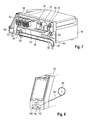
- FIG. 1 a cooking appliance for preparing food is shown, which is designed as a tabletop device.
- the maximum height h of the cooking appliance measured from the surface of the table on which it is placed, is 400 mm, in particular only a maximum of 350 mm, based on the closed state of the appliance.
- the cooking appliance comprises two crucibles 10, 12, which are upwardly open, internally one-piece containers (see FIG. 2 ).
- the crucibles 10, 12 can be opened or closed by preferably pivotable covers 14, 16.
- each crucible 10, 12 heating elements, not shown, are provided via which the bottom of the crucible can be electrically heated to cook in the crucible 10, 12 introduced food or to boil water.
- the crucibles are designed as a cuboid.
- Each crucible 10, 12 has a bottom, a front edge 18 (front), an opposite rear edge 20 (rear) and a first side edge 22 and an opposite side edge 24 (sides).
- the side edges 24 of the two crucibles 10, 12 face each other.
- Crucible 10, 12 and cover 14, 16 are pivotally mounted on an on-table frame 26, which is preferably carried out simultaneously as a housing of the cooking appliance.
- the on-table frame 26 is T-shaped in plan view of the cooking appliance, with a between the adjacent crucibles 10, 12 and the covers 14, 16 extending central web 28 and connected to the central web 28 transverse web 30.
- the transverse web 30 extends along the rear edges 20 of both crucibles 10, 12 so to speak from the left outside of the cooking appliance to the opposite right outside of the cooking appliance.
- Middle web 28 and crosspiece 30 are formed as a merging into each other hollow body.
- At least the transverse web 30 of the T is designed so that the frame simultaneously forms the self-supporting outer housing. This is true for all other embodiments.
- the central web 28 can also be designed accordingly or the frame can be clad here once again, since the frame in this section contains large-volume built-in parts that require large installation openings in the frame for installation.
- the two crucibles 10, 12 are, as in FIG. 2 can be seen, pivotally mounted on the frame, more precisely on the central web 28, by the center web 28 from opposite sides of pivot axes 32 (see FIGS. 1 and 7 ) protrude into the bottom of the crucible.
- the pivot axes 32 simultaneously serve as a sewer and have a fixed central bearing axis 34 and a bearing axis surrounding the axis of rotation 36, bearing and rotation axes 34 and 36 are designed as tubes. Between the bearing axis 34 and the axis of rotation 36 results in an annular gap 38, which is designed as a drainage channel.
- the pivot axis 32 is disposed very close to the front edge 10 and is relatively far below near the crucible bottom.
- Each crucible 10, 12 has in the region of its crucible bottom or the lower end of the front crucible wall, in the front central region an optionally closable outlet 40 (see FIG. 2 ), which is in the open state with the flow channel 38 in fluid communication.
- each crucible 10, 12 In the region of the outlet 40, the inside of the front wall of each crucible 10, 12 is provided with a pouring spout 42, which allows a complete pouring of the crucible contents with completely tilted crucible 10, 12.
- bearing is provided at some points between the bearing axis 34 and the rotation axis 36, so that the rotation axis 36 can rotate about the bearing axis 34.
- the axis of rotation 36 has in the region of the central web 28 (see FIG. 7 ) an outlet which communicates with another portion of the outlet channel 38 ', which extends along the bottom of the central web 28 to the back 44 of the cooking appliance and ends via an L-shaped outlet nozzle 46 down. At the outlet nozzle 46 is to be coupled from the bottom of a drain hose.
- the lid 14, 16 are pivotally mounted on the on-table frame 26, namely (see FIG. 2 ) via pivot axes 48, which emanate from the central web 28 and in this embodiment, free in the respective lid 14, 16 ends.
- the pivot axis 48 which is also in FIG. 7 can be seen optionally can also be designed as a feed for fresh water, by also here between an example fixed and a pivotable part an inlet channel 50 is formed.
- the cooking device is extremely compact, yet has very large crucibles and can be placed on a standard table in a kitchen checkout, without protruding over the table sideways or forward.
- the depth of the cooking appliance is preferably less than 850 mm.
- depths of less than 800 mm can be realized.
- the large crucible volume combined with compactness and a large tilt angle of the crucible 10, 12 of up to 60 ° or even more is achieved mainly by the particular embodiment of the on-table frame 26.
- the on-table frame is designed frame-free, that is, there is no supporting portion of the frame on the outside and the front of each crucible available.
- the crucible are completely pivoted and extend to the bottom of the cooking appliance.
- the central web 28 ends vertically approximately flush with the top of the lid 14, 16, so that the highest point of the cooking appliance in the region of the rear end of the lid 14, 16.
- the central web 28 projects upwards in relation to the upper side of the covers 14, 16 in order to form a splash guard.
- the embodiment according to the FIGS. 3 and 4 is substantially the same as the previous one, but the display 52 is arranged differently. With regard to all other features, however, the previous embodiments according to the Figures 1 and 2 to get expelled. In addition to the display 52, there is a further difference between these embodiments in that the transverse web 30 protrudes laterally somewhat opposite the crucibles 10, 12 and a holder 56 for supporting the swivel axis 48 is present at the second end of the swiveling axis 48.
- each crucible 10, 12 rests on the top or on a shoulder of the transverse web 30 when the respective crucible 10, 12 is not tipped.
- a support surface on the central web 28 may be present.
- the pivotal movement of the crucible 10, 12 and also the associated lid 14, 16 is preferably carried out purely mechanically.
- Corresponding handles 60 on the lid 14, 16 or on the crucible 10, 12 are easily feasible.
- the mechanical pivoting or tilting movement can generally by gas springs 62, which in FIG. 1 only symbolically indicated, are supported.
- the embodiment according to FIG. 5 is different from the previous one in that the transverse web 30 extends below the rear edge 20 of the crucibles 10, 12, so that it is even hidden from above.
- the edge 14 seen from above, the crosspiece 30 overlap only partially. This can increase the inner crucible volume.
- the cover storage is of importance, here the cover 14, 16 should be stored as far back and up to swing away enough and to make room for the tilting of the crucible.
- the electrical components preferably all electrical components, but in particular all electronic components 70 are housed inside the frame 26.
- the electronic components 70 are provided in the region of the rear wall.
- a transformer 72 is housed in the crossbar 30.
- electrical including electronic components may be provided inside the central web 28.
- Electrical components 74 such as relays or on-off switches are in FIG. 7 shown.
- FIG. 7 also that both the water, sewage and electrical wiring inside the frame 26 is realized.
- the back 44 From the back 44 (see FIG. 6 ) all energy connections are made.
- the back has a niche 80 drawn in the direction of the front, in which the fresh water connection 82, the electrical connection 84 and the waste water connection end with the connection 46 and are completely accommodated.
- the niche 80 is so deep that when the cables and hoses are connected, they do not protrude backwards relative to the rear wall 44, so that the rear wall can actually be pushed against a wall.
- FIG. 7 shows the electrical lead 90 which extends from the terminal 84 and extends to the display 52 and the on-off switch (electrical component 74 on the front).
- the fresh water connection 82 leads via a not completely shown line to the channel 50.
- a partition wall 92 (see FIG. 7 ) is provided between the electrical components and the electrical wiring and the water-carrying parts, so that the interior space in the central web 28 is divided into two spaces.
- FIG. 8 is another way to optimize the cooking appliance, shown, which can also be combined with all other features shown the other cooking appliances.
- the cooking appliance has integrated into the center bar 26 an extendable hand shower.
- the hand shower comprises a shower head 94 and a hose 96 extending from the shower head, which ends in a roll-up mechanism 98, which is housed in the central web 26 and is coupled to the fresh water connection 82.
- the shower head 94 (also in FIG. 3 shown) is received in a holder 100, the shape of which is adapted to the shower head 94, that the shower head has a defined orientation when the shower is retracted. In this orientation, the outlet 102 is located on the shower head 94 horizontally or facing down.
- the hose guide from the shower head 94 to the retractor 98 is directed obliquely upward. This results in an obliquely upward directed, defined fresh water channel.
- FIG. 10 is a further embodiment of the invention with respect to the arrangement and placement of the electrical and electronic components shown within the frame.
- the frame in the present case is the same housing and consists of several merging, rectangular in cross-section, tubular sections, which form a "T", wherein the interior of the "T" -shaped frame a large Chamber forms.
- the frame is closed to the environment, so has no Zu Kunststoff- or exhaust air slots.
- the frame forms a closed cooling space in itself.
- all the electronic components 70 are accommodated in the interior of the frame.
- FIG. 9 This cooling device is shown explicitly for the first time. It is an electrically driven cooling unit in the form of a cooling fan 110, which is housed in a lateral leg of the "T".
- the cooling fan 110 is located in the vicinity of the electrical component that is located inside the frame 26, which is the hottest in operation.
- this component which has the highest cooling requirement, is a solid state relay, abbreviated SSR component.
- the cooling fan 110 is coupled to an air guide element 112 in the form of a sheet, more precisely fastened to it, which conveys the sucked air to a plurality of immediately adjacent relays 114.
- the relays 114 are mounted on a common component carrier 116. Preferably, they lie directly against him.
- the component carrier is made of a metal, here light metal in the form of aluminum.
- On the front of the component carrier carries the relay 114, from the back are several molded cooling fins 118 from. These cooling fins 118 extend to or close to contact with a wall 120 to form a cooling channel 122 which is subdivided by the fins 118 into subchannels.
- the wall 120 may also form the wall of the frame 26.
- the air guide element 112 deflects the air from the cooling channel 122 so that it flows in the opposite direction in a further, adjacent cooling channel 124 from the end of a leg of the "T" back toward the central web, preferably on the wall of the housing 26 along.
- one or more further air guide elements 112 " are provided, which preferably direct the air along the arrow A along one side of the frame in the region of the central web and lead along the arrow B into the other leg of the" T ".
- the inflowing warm air cools down in these areas and can specifically flow along the cooling channels, which are delimited by components and air guide elements, back to the cooling fan 110 as intake air.
- the illustrated active cooling device is designed without a filter and therefore maintenance-free.
- the transverse web of the L-shaped or T-shaped frame running along the rear edge of the crucible can contain all or some of the electronic components (except for the display and the externally operated switches).
- the illustrated housing of all electronic components (except for the display and the switch to be operated from outside) in the frame can also be used in normal stationary devices in which the frame extends to the bottom.
Landscapes
- Engineering & Computer Science (AREA)
- Food Science & Technology (AREA)
- Cookers (AREA)
- Commercial Cooking Devices (AREA)
- Baking, Grill, Roasting (AREA)
Abstract
Description
- Die Erfindung betrifft ein Gargerät zum Zubereiten von Speisen, mit wenigstens einem kippbar gelagerten, beheizbaren Tiegel, einem vorzugsweise schwenkbaren Deckel zum Öffnen und Schließen des Tiegels sowie einem Gestell, das den Tiegel trägt, wobei der Tiegel einen Boden und einen vorderen, einen hinteren sowie seitliche Ränder hat.
- Gargeräte mit Tiegel sind äußerst universell einsetzbar. Mit ihnen ist es möglich, im Tiegel zu braten, zu kochen, zu frittieren, aufzuwärmen und dergleichen. Die bisherigen Gargeräte mit Garbehältern, wie Tiegel, sind fest mit einem tragenden Gestell verbunden, das entweder bis zum Boden reicht und oftmals durch Rollen verfahrbar ist, oder an einer Wand aufgehängt werden kann. Das hauptsächlich aus Rohren gebildete Gestell ist meist mit einer Blechverkleidung, die das Gehäuse bildet, versehen. Der Tiegel kippt mit dem vorderen Rand zum Entleeren zum Beispiel bei flüssigen Speisen um etwa 60° bis 90° nach unten, um die Speisen aus dem Tiegel in einen Behälter zu überführen.
- Die Erfindung hat es sich zum Ziel gesetzt, ein kompakt aufgebautes Gargerät mit Tiegel, z.B. in Form eines Tisch-Gargeräts, auszubilden.
- Dies wird bei einem Gargerät der eingangs genannten Art dadurch erreicht, dass im Gestell elektronische Bauteile untergebracht sind. Das Gestell ist das tragende Teil des Gargeräts, welches das Gewicht des oder der Tiegel bis in den Fixiergrund, also den Boden, eine Wand oder, bei einem Auf-Tisch-Gerät, in den Tisch einleitet, wobei in diesem Fall natürlich auch Füße oder einstellbare Füße vorgesehen sein können. Bei den bisherigen Gargeräten waren die elektronischen Bauteile außerhalb des Gestells, zwischen diesem und dem Gehäuse untergebracht, um die Zugänglichkeit für die Montage sicherzustellen.
- Die elektronischen Bauteile sind beispielsweise Leiterplatten, die im Gestell selbst platzsparend und sicher untergebracht werden können. Elektrische Bauteile wie Schütze, Trafos, ect., die ein großes Volumen und Gewicht aufweisen, sind ebenfalls im Gestell unterbringbar. Elektronische Bauteile sind eine Untergruppe von elektrischen Bauteilen.
- Das Gestell kann durch zusammengesetzte Hohlkörper gebildet sein, beispielsweise durch vorgefertigte, miteinander verschweißte Rohre oder gekantete und miteinander verbundene, z.B. verschweißte Blechteile.
- Wenn das Gestell durch einfeststehendes, selbsttragendes Gehäuse des Gargeräts gebildet wird, ist darüber hinaus keine weitere Verkleidung (Einhausung) mehr notwendig. Damit verschmelzen sozusagen Verkleidung und Gestell ineinander, was für eine Minimierung der Bauteile sorgt. Darüber hinaus ist damit die Verkleidung insgesamt sehr stabil und robust, denn sie wird durch das Gestell gebildet. Temperaturbeständige, kratzfeste großvolumige aufgesetzte zusätzliche Verkleidungsschalen und dergleichen können damit zumindest teilweiseüberflüssig werden.
- Die bevorzugte Ausführungsform sieht vor, dass sämtliche elektronischen Bauteile ausgenommen von außen sichtbare Displays und von außen bedienbare Schalter innerhalb des Gestells angeordnet sind.
- Das erfindungsgemäße Gargerät hat eine aktive Kühleinrichtung für die elektronischen/elektrischen Bauteile, mit wenigstens einer im Inneren des Gestells untergebrachten, elektrisch angetriebenen Kühleinheit. Diese Kühleinheit ist insbesondere ein Kühllüfter. Über diese Kühleinrichtung werden die Bauteile gezielt gekühlt. Darüber hinaus wird die warme Luft im Inneren des Gestells verteilt und kann somit über eine größere Oberfläche gekühlt werden. Diese Idee ist insbesondere bei Auf-Tisch-Geräten sehr vorteilhaft, denn diese sind extrem kompakt.
- Die bevorzugte Ausführungsform sieht vor, dass die aktive Kühleinrichtung filterlos ausgeführt ist, das heißt, es ist kein Staub- oder Fettfilter vorhanden, der ausgetauscht werden müsste.
- Eine weitere Verbesserung wird dadurch erreicht, dass das Gestell einen zur Umgebung geschlossenen Kühlraum bildet. Im Gestell selbst sind also keine Schlitze für Zuluft oder Abluft vorhanden, die einen gezielten Luftaustausch mit der Umgebung herbeiführen und für einen Transport von kühler Umgebungsluft und Abtransport von heißer Luft sorgen würden. Natürlich können im Bereich von beispielsweise Befestigungsöffnungen noch geringfügige Schlitze vorhanden sein, so dass kein hermetisch abgeschlossener Raum im Inneren des Gestells gebildet ist, separate Kühlluftöffnungen sind jedoch, wie gesagt, nicht vorhanden.
- Im Gestell sind Luftleitelemente möglich, die die Luftzirkulation beeinflussen. Damit wird heiße Luft aus den besonders warmen elektronischen oder elektrischen Bauteilen in Abschnitte im Inneren des Gestells geführt, in denen weniger Wärme entsteht.
- Eine Ausführungsform der Erfindung sieht vor, dass ein gegenüber dem Gestell als separates Teil ausgebildeter Komponententräger aus Metall, vorzugsweise Leichtmetall wie Aluminium, im Inneren des Gestells vorgesehen ist. An einer Seite trägt der Komponententräger ein oder mehrere elektrische oder elektronische Bauteile. Ein solches Bauteil ist insbesondere ein Solid State Relais, welches zum Schalten von großen Strömen in den Heizsystemen von Gargeräten verwendet wird. Solche Relais produzieren eine starke Abwärme, sind aber auf der anderen Seite zuverlässig unter einer Temperatur von 90 °C zu halten. Der Komponententräger hat zu diesem Zweck Kühlrippen.
- Zwischen dem Komponententräger und der Innenseite des Gestells kann ein Kühlkanal gebildet sein, der durch die Rippen in Teilkanäle untergliedert wird. Diese Ausführungsform schafft auf einfache Weise kühlluftführende Kanäle und grenzt den Kühlluftstrom genau ein.
- Durch die vorliegende Erfindung wird der gesamte Innenraum des Gestells verwendet, um eine permanente Luftzirkulation zu erzeugen, die einen Wärmestau an den temperaturempfindlichen elektronischen oder elektrischen Bauteilen vermeidet. Es treten keine Wärmestaus auf. Die sogenannte Umluftkühlung, die erzeugt wird, sorgt dafür, dass an den Solid State Relais Temperaturen von 60 °C bis 85 °C an der Oberfläche herrschen. In den übrigen Abschnitten des Gestells erhöhen sich die Temperaturen auf etwas über 40 °C, was die wirksame Wärmeabfuhr durch die vorliegende Erfindung unterstreicht.
- Dadurch, dass kein Luftaustausch mit der Umgebung stattfindet, wird auch keine verschmutzte Luft angesaugt, die zu einer abnehmenden Kühlwirkung im Inneren des Gestells führen könnte. Auch ist kein Aufwand für Pflege und Wartung (z.B. durch Reinigung oder Filterwechsel) nötig. Die Gefahr des Eintritts von Dampf Aerosolen oder Wasser aufgrund Undichtigkeiten von Filtern wird ausgeschaltet.
- Die vorliegende Erfindung betrifft insbesondere ein sogenanntes Auf-Tisch-Gargerät, welches als Gestell ein Auf-Tisch-Gestell aufweist.
- Ein Auf-Tisch-Gestell im Sinne der Erfindung ist lediglich so hoch, dass das gesamte Gargerät insgesamt eine maximale Höhe vom Fuß des Gestells bis zur Oberkante, die durch den Deckel oder durch das gegebenenfalls über den Deckel überstehende Gestell gebildet sein kann, von 400 mm, insbesondere von maximal nur 350 mm aufweist. Um die Tiefe des Gargeräts zu reduzieren und um gleichzeitig den Tiegel möglichst weit nach vorne zu platzieren, hat das erfindungsgemäße Gargerät ein Auf-Tisch-Gestell, das eine komplette Lücke im Bereich des vorderen Randes, das heißt der Vorderseite des Tiegels besitzt. Mit anderen Worten, im Bereich des vorderen Randes, das heißt vor dem Tiegel oder unter dem Tiegel im Bereich des vorderen Randes ist kein Gestell vorhanden.
- Die bevorzugte Ausführungsform sieht vor, dass das Gerät sogar an einem zum vorderen Rand angrenzenden seitlichen Rand, das heißt an einer Tiegel-Längsseite, zumindest im Übergangsbereich zum vorderen Rand ebenfalls gestellfrei ausgeführt ist, sodass zumindest der gesamte Eckbereich frei ist.
- Wichtig ist natürlich, dass der Schwerpunkt des ganzen Gargeräts immer innerhalb des Mehrecks liegt, das durch die Kontaktstellen des Gestells mit dem Tisch, auf dem es steht, umschrieben ist. Dann kann das Gargerät unabhängig von seinem Befüllgrad und vom Schwenkwinkel des Tiegels nicht kippen.
- Insbesondere ist auch längs des gesamten seitlichen Randes des Tiegels kein Auf-Tisch-Gestell vorhanden. Damit wird einerseits die Zugänglichkeit zum Tiegel verbessert, und andererseits wird zusätzlich der Schwenkwinkel für den Tiegel und dessen Volumen, bei minimaler Breite des Gargeräts, maximiert, denn auch seitlich ist kein Gestell unterhalb oder neben dem Tiegel vorhanden, was aber nur für eine der beiden Seitenflächen der Fall ist.
- Das Auf-Tisch-Gargerät ist in sich standfest, unabhängig vom Beladungszustand.
- Der einem Tiegel zugeordnete Gestellabschnitt ist in Draufsicht beispielsweise L-förmig und verläuft längs des hinteren und eines der beiden seitlichen Ränder. Zwischen dem "L" ist der Tiegel angeordnet. Das seitliche Bauvolumen wird durch das fehlende Gestell an einer Längsseite des Tiegels zusätzlich reduziert.
- Das erfindungsgemäße Gargerät kann zwar mit einem einzelnen Tiegel ausgestattet sein, bevorzugt sind jedoch zwei Tiegel nebeneinander angeordnet. Das Auf-Tisch-Gestell ist ein gemeinsames Auf-Tisch-Gestell und ist in Draufsicht T-förmig ausgebildet. Zwischen den Tiegeln verläuft ein Mittelsteg des Gestells. Ein Quersteg des "T" erstreckt sich längs der hinteren Ränder der beiden Tiegel. Beide Tiegel haben also an ihren jeweiligen äußeren Seitenrändern kein Gestell, sondern nur jeweils an dem dem anderen Tiegel zugewandten Seitenrand.
- Die Erfindung sieht insbesondere vor, dass der längs des hinteren Tiegelrandes verlaufende Quersteg des L-förmigen oder T-förmigen Gestells alle oder einige der elektronischen Bauteile (bis auf Display und die von außen zu bedienenden Schalter) enthält. Durch diese Idee ist es möglich, weniger oder keine elektronischen Bauteile in den Mittelsteg des L oder des T zu legen, womit dieser schmal ausgeführt werden kann.
- Beim Auf-Tisch-Gargerät mit Auf-Tisch-Gestell ist zumindest der Quersteg des L oder T so ausgeführt, dass das Gestell gleichzeitig das dadurch selbsttragende Außengehäuse bildet. Natürlich können für die Montage Öffnungen vorgesehen sein, die durch Blech- oder Kunststoffabdeckungen geschlossen werden.
- Wenn der Mittelsteg gegenüber der Oberseite der geschlossenen Deckel nach oben vorsteht, kann er zusätzlich auch als Spritzschutz zumindest in eingeschränktem Umfang dienen, womit verhindert wird, dass Speisen oder Garhilfsmedien wie Wasser oder Öl von einem Tiegel in den benachbarten Tiegel spritzen können.
- Die elektrischen Bauteile wie Schütze und Trafos sollten im Quersteg untergebracht sein, denn ihr Gewicht sorgt dafür, dass der Gesamtschwerpunkt des Gargeräts nach hinten und durch die Verteilung nach links bzw. rechts in eine stabile Mitte wandert.
- Eine weitere bevorzugte Ausführungsform in diesem Zusammenhang sieht vor, dass im Mittelsteg elektrische Bauteile und/oder flüssigkeitsführende Bauteile untergebracht sind. Sind sowohl elektrische Bauteile als auch flüssigkeitsführende Bauteile vorhanden, sollte eine Trennwand zwischen den Räumen innerhalb des Mittelstegs, in denen elektrische Bauteile untergebracht sind, und Räumen, in denen flüssigkeitsführende Bauteile untergebracht sind, vorhanden sein. Damit ist auch rein räumlich Strom von Wasser getrennt.
- Natürlich lässt sich diese Ausführungsform, die auf die Unterbringung der elektrischen Bauteile gerichtet ist, auch bei den zuvor erwähnten Ausführungsformen anwenden und mit ihnen kombinieren.
- Im Mittelsteg kann eine frei auskragende Schwenkachse für den zugeordneten Tiegel gelagert sein. Insbesondere bildet die Schwenkachse in ihrem Inneren einen von einem Tiegelboden ausgehenden Ablaufkanal, der längs des Mittelstegs in Richtung zum Quersteg verläuft. Für diese Ausführungsform ist es unnötig, am vorderen Ende des Tiegelbodens bzw. am unteren Ende der vorderen Tiegelwand einen nach unten abstehenden Ablaufhahn oder dergleichen vorzusehen, der sich erneut negativ auf den Schwenkwinkel auswirken würde. Vielmehr kann der Tiegelinhalt, zum Beispiel Wasser oder Reinigungsflüssigkeit mit Wasser, über die Schwenkachse entleert werden. Die Schwenkachse kann in diesem Zusammenhang entweder feststehend sein oder auch in Form eines Doppelrohres ausgeführt sein, wobei das innenstehende Rohr fest ist und das außenstehende Rohr den schwenkbaren Teil des Lagers bildet. Zwischen Innen- und Außenrohr ist dann ein Ringspalt vorhanden, der als Ablaufkanal dient.
- Die Kompaktheit wird ferner dadurch verbessert, dass der längs des hinteren Randes verlaufende Abschnitt des Auf-Tisch-Gestells teilweise oder ganz unterhalb des hinteren Randes des Tiegels verläuft. Das bedeutet, das Gestell verläuft, in Draufsicht gesehen, nicht angrenzend an den hinteren Rand des Tiegels, sondern zumindest teilweise, vorzugsweise vollständig unterhalb des Tiegels, wodurch die Bautiefe des Gargeräts bei großem Tiegelvolumen gering gehalten werden kann.
- Eine weitere Lösung zur Schaffung eines eine geringe Tiefe aufweisenden Gargeräts besteht darin, dass ein Gargerät nach der eingangs genannten Art im Bereich der Rückseite des Auf-Tisch-Gestells mit einer in Richtung Vorderseite eingezogenen Anschlussnische ausgestattet ist, in der zumindest ein Wasser-und/oder wenigstens ein Elektroanschluss endet. Unter "Wasseranschluss" fällt sowohl ein Frischwasseranschluss heiß und/oder kalt als auch ein Abwasseranschluss. Durch die Anschlussnische stehen die zwangsläufig notwendigen Kupplungsstücke an den Enden der Wasserschläuche oder Elektrokabel nicht mehr gegenüber dem Gargerät nach hinten gegenüber der Rückseite des Geräts vor. Auch werden die Schlauch- und Elektroanschlüsse nicht mehr permanent mechanisch belastet, weil ansonsten sie das am weitesten nach hinten vorstehende Teil des angeschlossenen Gargeräts bilden und oftmals permanent gegen die angrenzende Wand gedrückt werden.
- Im nicht verschwenkten Zustand sollte der Tiegel im Bereich seines hinteren Randes auf dem Auf-Tisch-Gestell aufliegen, sodass dieses eine Art Anschlag bildet. Durch das Aufliegen längs des Randes erhöht sich darüber hinaus auch die Stabilität des Geräts und vor allem des Tiegels beim Garen.
- Deckel und/oder Tiegel sollten mechanisch und/oder motorisch angetrieben schwenkbar sein. Es kann aber auch zusätzlich eine die Schwenkbewegung unterstützende Gasdruck- oder mechanische Feder vorhanden sein, um die notwendigen motorischen Kräfte zu reduzieren.
- Ein erfindungsgemäßes Gargerät ist darüber hinaus gemäß einer Ausführungsform mit einer ausziehbaren Handbrause versehen, die mit einem Schlaufen- oder Wickelmechanismus, vorzugsweise mit einem Aufrollmechanismus für den Schlauch ausgestattet ist. Der Aufrollmechanismus samt des Schlauchs ist im Auf-Tisch-Gestell untergebracht. Im eingezogenen Zustand der Handbrause sind deren Brausekopf, der außerhalb des Auf-Tisch-Geräts greifbar für den Benutzer liegt, und der Schlauch so gelagert, dass der durch Brausekopf und Schlauch definierte Kanal vom Auslass im Brausekopf bis zum Erreichen des Aufrollmechanismus schräg aufwärts verläuft. Dadurch wird verhindert, dass eventuelle Speisereste im Bereich des Brausekopfes zum Kontaminieren des im Schlauch stehenden Wassers führen. Bei der Erfindung verläuft der Schlauch zum Auslass im Brausekopf abwärts. Weitere Merkmale und Vorteile der Erfindung ergeben sich aus der nachfolgenden Beschreibung und aus den nachfolgenden Zeichnungen, auf die Bezug genommen wird. In den Zeichnungen zeigen:
-
Figur 1 eine perspektivische Draufsicht auf eine erste Ausführungsform des erfindungsgemäßen Gargeräts, -
Figur 2 das Gargerät vonFigur 1 mit hochgeschwenkten Deckeln und einem gekippten Tiegel, -
Figur 3 eine perspektivische Draufsicht auf eine zweite Ausführungsform des erfindungsgemäßen Gargeräts, -
Figur 4 eine perspektivische Seitenansicht des Gargeräts nachFigur 3 mit hochgeschwenkten Deckeln und einem gekippten Tiegel, -
Figur 5 eine perspektivische Ansicht einer dritten Ausführungsform des erfindungsgemäßen Gargeräts, bei dem ein Deckel zur Verbesserung der Übersichtlichkeit weggelassen ist, -
Figur 6 eine Rückansicht des Gargeräts nachFigur 3 mit aufgeschnittener Rückwand, -
Figur 7 eine Längsschnittansicht durch das Gargerät nachFigur 3 längs des Mittelstegs, -
Figur 8 eine Frontansicht des Mittelstegs eines erfindungsgemäßen Gargeräts, -
Figur 9 eine horizontale Schnittansicht durch ein erfindungsgemäßes Gargerät, das ähnlich zu dem inFigur 3 ist, und -
Figur 10 eine Detailansicht des Gestells des Gargeräts nachFigur 9 im Bereich von Solid State Relais. - In
Figur 1 ist ein Gargerät zum Zubereiten von Speisen dargestellt, welches als Tischgerät ausgeführt ist. Das bedeutet, die maximale Höhe h des Gargeräts, gemessen von der Oberfläche des Tisches, auf dem es aufgesetzt ist, beträgt 400 mm, insbesondere nur maximal 350 mm, bezogen auf den geschlossenen Zustand des Geräts. - Das Gargerät umfasst zwei Tiegel 10, 12, die nach oben offene, innenseitig einstückige Behälter darstellen (siehe
Figur 2 ). Die Tiegel 10, 12 können durch vorzugsweise schwenkbare Deckel 14, 16 geöffnet oder geschlossen werden. - Auf der Unterseite jedes Tiegels 10, 12 sind nicht gezeigte Heizelemente vorgesehen, über die der Tiegelboden elektrisch beheizt werden kann, um in den Tiegel 10, 12 eingebrachte Speisen zu garen oder auch Wasser zu kochen. Die Tiegel sind als Quader ausgebildet.
- Jeder Tiegel 10, 12 hat einen Boden, einen vorderen Rand 18 (Vorderseite), einen entgegengesetzten hinteren Rand 20 (Hinterseite) sowie einen ersten Seitenrand 22 und einen entgegengesetzten Seitenrand 24 (Seiten). Die Seitenränder 24 der beiden Tiegel 10, 12 sind einander zugewandt.
- Tiegel 10, 12 und Deckel 14, 16 sind an einem Auf-Tisch-Gestell 26 schwenkbar angebracht, welches vorzugsweise gleichzeitig als Gehäuse des Gargeräts ausgeführt ist.
- Das Auf-Tisch-Gestell 26 ist in Draufsicht auf das Gargerät T-förmig ausgebildet, mit einem zwischen den benachbarten Tiegeln 10, 12 und den Deckeln 14, 16 verlaufenden Mittelsteg 28 sowie einem mit dem Mittelsteg 28 verbundenen Quersteg 30. Der Quersteg 30 erstreckt sich längs der hinteren Ränder 20 beider Tiegel 10, 12 sozusagen von der linken Außenseite des Gargeräts bis zur entgegengesetzten rechten Außenseite des Gargeräts.
- Mittelsteg 28 und Quersteg 30 sind als ineinander übergehende Hohlkörper ausgebildet.
- Zumindest der Quersteg 30 des T ist so ausgeführt, dass das Gestell gleichzeitig das dadurch selbsttragende Außengehäuse bildet. Dies gilt im übrigen für alle Ausführungsformen.
- Der Mittelsteg 28 kann auch entsprechend ausgeführt sein oder das Gestell kann hier noch einmal verkleidet werden, da das Gestell in diesem Abschnitt großvolumige Einbauteile enthält, die große Einbauöffnungen im Gestell zur Montage erfordern.
- Die beiden Tiegel 10, 12 sind, wie in
Figur 2 zu sehen ist, schwenkbar am Gestell, genauer gesagt am Mittelsteg 28 gelagert, indem vom Mittelsteg 28 von gegenüberliegenden Seiten Schwenkachsen 32 (sieheFiguren 1 und7 ) in den Boden des Tiegels ragen. Die Schwenkachsen 32 dienen gleichzeitig als Abwasserkanal und haben eine feststehende mittige Lagerachse 34 sowie eine die Lagerachse umgebende Drehachse 36, wobei Lager- und Drehachse 34 bzw. 36 als Rohre ausgeführt sind. Zwischen der Lagerachse 34 und der Drehachse 36 ergibt sich ein Ringspalt 38, der als Ablaufkanal ausgeführt ist. - Die Schwenkachse 32 ist sehr nahe am vorderen Rand 10 angeordnet und liegt relativ weit unten nahe dem Tiegelboden. Jeder Tiegel 10, 12 hat im Bereich seines Tiegelbodens oder des unteren Endes der vorderen Tiegelwand, und zwar im vorderen mittigen Bereich einen wahlweise verschließbaren Auslass 40 (siehe
Figur 2 ), der in geöffnetem Zustand mit dem Ablaufkanal 38 in Strömungsverbindung steht. - Im Bereich des Auslasses 40 ist die Innenseite der vorderen Wand jedes Tiegels 10, 12 mit einer Ausgießrinne 42 versehen, die ein komplettes Ausgießen des Tiegelinhalts bei komplett hochgekipptem Tiegel 10, 12 ermöglicht.
- Zwischen Lagerachse 34 und Drehachse 36 sind an einigen Stellen natürlich Lager vorgesehen, sodass sich die Drehachse 36 um die Lagerachse 34 drehen kann.
- Die Drehachse 36 hat im Bereich des Mittelstegs 28 (siehe
Figur 7 ) einen Auslass, der mit einem weiteren Abschnitt des Auslasskanals 38' in Verbindung steht, welcher sich entlang des Bodens des Mittelstegs 28 bis zur Rückseite 44 des Gargeräts erstreckt und über einen L-förmigen Ablaufstutzen 46 nach unten endet. An den Ablaufstutzen 46 ist von der Unterseite aus ein Ablaufschlauch anzukoppeln. - Auch die Deckel 14, 16 sind schwenkbar am Auf-Tisch-Gestell 26 gelagert, und zwar (siehe
Figur 2 ) über Schwenkachsen 48, die vom Mittelsteg 28 ausgehen und bei dieser Ausführungsform frei im jeweiligen Deckel 14, 16 enden. - Die Schwenkachse 48, die auch in
Figur 7 zu sehen ist, kann optional auch als Zulauf für Frischwasser ausgeführt sein, indem auch hier zwischen einem beispielsweise feststehenden und einem schwenkbaren Teil ein Zulaufkanal 50 entsteht. - Das Gargerät baut extrem kompakt, hat dennoch sehr große Tiegel und ist auf einem normalen Tisch in einer Pröfiküche unterbringbar, ohne über den Tisch seitlich oder nach vorne vorzustehen. Die Tiefe des Gargeräts beträgt vorzugsweise weniger als 850 mm. Abhängig von der Ausführung und Positionierung des Bedienerdisplays 52, welches in
Figur 1 nach vorne absteht, können Tiefen von unter 800 mm realisiert werden. - Das große Tiegelvolumen kombiniert mit Kompaktheit und einem großen Kippwinkel der Tiegel 10, 12 von bis zu 60° oder auch mehr wird vor allem durch die besondere Ausführungsform des Auf-Tisch-Gestells 26 erreicht. Das Auf-Tisch-Gestell 26 mit seiner T-Form umrahmt jeden Tiegel 10, 12 nämlich nur in Draufsicht L-förmig und verläuft nur längs des hinteren Randes 20 und eines seitlichen Randes 24. Am vorderen Rand 18 sowie bei der gezeigten Ausführungsform sogar längs des gesamten seitlichen Randes 22 ist das Auf-Tisch-Gestell gestellfrei ausgeführt, das heißt, es ist kein tragender Abschnitt des Gestells an der Außenseite und der Vorderseite jedes Tiegels vorhanden. Damit kann, wie in
Figur 2 und für eine andere Ausführungsform inFigur 4 gut zu erkennen ist, der Tiegel komplett geschwenkt werden und sich bis zum unteren Ende des Gargerätes erstrecken. - Bei der in
Figur 1 dargestellten Ausführungsform endet der Mittelsteg 28 vertikal in etwa bündig mit der Oberseite des Deckels 14, 16, sodass die höchste Stelle des Gargerätes im Bereich des hinteren Endes der Deckel 14, 16 ist. Bei der Ausführungsform nachFigur 5 steht der Mittelsteg 28 gegenüber der Oberseite der Deckel 14, 16 nach oben vor, um einen Spritzschutz zu bilden. - Die Ausführungsform nach den
Figuren 3 und 4 entspricht im Wesentlichen der vorhergehenden, wobei das Display 52 jedoch anders angeordnet ist. Bezüglich sämtlicher anderer Merkmale kann jedoch auf die vorhergehenden Ausführungsformen nach denFiguren 1 und 2 verwiesen werden. Neben dem Display 52 besteht noch ein weiterer Unterschied dieser Ausführungsformen darin, dass der Quersteg 30 seitlich etwas gegenüber den Tiegeln 10, 12 vorsteht und ein Halter 56 für die Lagerung der Schwenkachse 48 am zweiten Ende der Schwenkachse 48 vorhanden ist. - Bei sämtlichen Ausführungsformen liegt der hintere Rand 20 jedes Tiegels 10, 12 auf der Oberseite oder auf einem Absatz des Querstegs 30 auf, wenn der jeweilige Tiegel 10, 12 ungekippt ist. Zusätzlich kann auch noch eine Auflagefläche am Mittelsteg 28 vorhanden sein.
- Die Schwenkbewegung des Tiegels 10, 12 und auch des zugeordneten Deckels 14, 16 erfolgt vorzugsweise rein mechanisch. Entsprechende Griffe 60 am Deckel 14, 16 oder am Tiegel 10, 12 sind einfach verwirklichbar. Alternativ hierzu sind die beiden Tiegel 10, 12 auch motorisch kippbar.
- Die mechanische Schwenk- oder Kippbewegung kann generell durch Gasdruckfedern 62, die in
Figur 1 nur symbolisch angedeutet sind, unterstützt werden. - Die Ausführungsform nach
Figur 5 ist insofern unterschiedlich zu den vorherigen, als dass sich der Quersteg 30 unterhalb des hinteren Randes 20 der Tiegel 10, 12 erstreckt, sodass er von oben gesehen sogar verdeckt ist. Alternativ hierzu kann der Rand 14 von oben gesehen den Quersteg 30 auch nur teilweise überdecken. Damit lässt sich das innere Tiegelvolumen erhöhen. - Bei dieser Ausführungsform ist insbesondere die Deckellagerung von Bedeutung, hier sollten die Deckel 14, 16 möglichst weit hinten und oben gelagert werden, um ausreichend wegzuschwenken und Platz für das Kippen des Tiegels zu machen. In diesem Zusammenhang kann es sinnvoll sein, die Deckel 14, 16 etwas exzentrisch zu lagern, sodass die Achse 48 beim Hochschwenken selbst auch noch nach oben schwenkt.
- Um das Gargerät möglichst kompakt auszuführen und glatte Außenflächen zu erzeugen, ist zumindest ein Teil der elektrischen Bauteile, vorzugsweise sämtliche elektrischen Bauteile, insbesondere aber sind zumindest sämtliche elektronischen Bauteile 70 im Inneren des Gestells 26 untergebracht. In
Figur 6 ist zu sehen, dass die elektronischen Bauteile 70 im Bereich der Rückwand vorgesehen sind. - Auch ein Trafo 72 ist im Quersteg 30 untergebracht.
- Natürlich können auch elektrische, darunter elektronische Bauteile im Inneren des Mittelstegs 28 vorgesehen sein. Elektrische Bauteile 74 wie Relais oder Ein-Aus-Schalter sind in
Figur 7 dargestellt. - Gut zu erkennen ist im Schnitt nach
Figur 7 auch, dass sowohl die Wasser-, Abwasser- als auch elektrische Leitungsführung im Inneren des Gestells 26 realisiert ist. - Von der Rückseite 44 aus (siehe
Figur 6 ) erfolgen alle Energieanschlüsse. Hierzu hat die Rückseite eine in Richtung Vorderseite gezogene Anschlussnische 80, in der der Frischwasseranschluss 82, der elektrische Anschluss 84 sowie der Abwasseranschluss mit dem Stutzen 46 enden und vollständig untergebracht sind. - Die Nische 80 ist so tief, dass bei angeschlossenen Kabeln und Schläuchen diese nicht gegenüber der Rückwand 44 nach hinten vorstehen, sodass die Rückwand tatsächlich an eine Wand herangeschoben werden kann.
-
Figur 7 zeigt die elektrische Leitung 90, die vom Anschluss 84 ausgeht und bis zum Display 52 und zum Ein-Aus-Schalter (elektrisches Bauteil 74 an der Vorderseite) reicht. Der Frischwasseranschluss 82 führt über eine nicht komplett dargestellte Leitung zu dem Kanal 50. - Vorzugsweise ist eine Trennwand 92 (siehe
Figur 7 ) zwischen den elektrischen Bauteilen und der elektrischen Leitungsführung und den Wasser führenden Teilen vorgesehen, sodass der Innenraum im Mittelsteg 28 in zwei Räume untergliedert wird. - Diese wie auch die übrigen Merkmale der verschiedenen Ausführungsformen der Gargeräte können beliebig miteinander kombiniert werden.
- In
Figur 8 ist eine weitere Möglichkeit, das Gargerät zu optimieren, dargestellt, die ebenfalls mit sämtlichen übrigen gezeigten Merkmalen der anderen Gargeräte kombiniert werden kann. - Das Gargerät hat integriert in den Mittelsteg 26 eine ausziehbare Handbrause. Die Handbrause umfasst einen Brausekopf 94 sowie einen vom Brausekopf ausgehenden Schlauch 96, der in einem Aufrollmechanismus 98 endet, welcher im Mittelsteg 26 untergebracht ist und mit dem Frischwasseranschluss 82 gekoppelt ist.
- Der Brausekopf 94 (auch in
Figur 3 gezeigt) ist in einer Halterung 100 aufgenommen, deren Form so auf den Brausekopf 94 abgestimmt ist, dass der Brausekopf bei eingezogener Brause eine definierte Ausrichtung hat. In dieser Ausrichtung liegt der Auslass 102 am Brausekopf 94 waagerecht oder nach unten weisend. Die Schlauchführung vom Brausekopf 94 bis zum Aufrollmechanismus 98 ist schräg aufwärts gerichtet. Damit ergibt sich ein schräg aufwärts gerichteter, definierter Frischwasserkanal. - In
Figur 10 ist eine weitere Ausführungsform der Erfindung bezüglich der Anordnung und Unterbringung der elektrischen und elektronischen Bauteile innerhalb des Gestells dargestellt. - Wie auch bei den anderen Ausführungsformen ist das Gestell im vorliegenden Fall gleichzeitig das Gehäuse und besteht aus mehreren ineinander übergehenden, im Querschnitt rechteckigen, rohrförmigen Abschnitten, die sich zu einem "T" zusammensetzen, wobei der Innenraum des "T"-förmigen Gestells eine große Kammer bildet.
- Ebenfalls wie auch bei den übrigen Ausführungsformen ist das Gestell zur Umgebung hin geschlossen, hat also keine Zuluft- oder Abluftschlitze. Damit bildet das Gestell in sich einen geschlossenen Kühlraum.
- Wie auch bei den übrigen Ausführungsformen, die vorliegend schon erläutert worden sind, sind sämtliche elektronischen Bauteile 70, vorzugsweise sogar sämtliche elektrischen Bauteile im Inneren des Gestells untergebracht.
- Bei den übrigen Ausführungsformen ist es zwar nicht gezeigt, es gilt jedoch auch für diese, dass im Inneren des Gestells eine aktive Kühleinrichtung für die elektronischen und/oder elektrische Bauteile vorhanden ist. In
Figur 9 ist diese Kühleinrichtung erstmals explizit dargestellt. Es handelt sich um eine elektrisch angetriebene Kühleinheit in Form eines Kühllüfters 110, der in einem seitlichen Schenkel des "T" untergebracht ist. - Der Kühllüfter 110 ist in der Nähe desjenigen elektrischen Bauteils, das sich im Inneren des Gestells 26 befindet, angeordnet, welches im Betrieb am heißesten wird.
- In der dargestellten Ausführungsform ist dieses, den höchsten Kühlbedarf aufweisende Bauteil ein Solid States Relais, abgekürzt SSR-Bauteil.
- Der Kühllüfter 110 ist mit einem Luftleitelement 112 in Form eines Blechs gekoppelt, genauer gesagt an ihm befestigt, welches die angesaugte Luft zu mehreren, unmittelbar hintereinander angeordneten Relais 114 fördert.
- Wie in
Figur 10 zu erkennen ist, sind die Relais 114 auf einem gemeinsamen Komponententräger 116 befestigt. Vorzugsweise liegen sie unmittelbar an ihm an. - Der Komponententräger ist aus einem Metall, hier Leichtmetall in Form von Aluminium. Auf der Vorderseite trägt der Komponententräger die Relais 114, von der Rückseite stehen mehrere angeformte Kühlrippen 118 ab. Diese Kühlrippen 118 erstrecken sich bis nahe zu oder bis zum Kontakt an eine Wand 120, um einen Kühlkanal 122 zu bilden, der durch die Rippen 118 in Teilkanäle untergliedert ist.
- Die Wand 120 kann auch die Wand des Gestells 26 bilden.
- Ein am Ende des Kühlkanals 122 sitzendes, in
Figur 9 zu sehendes Luftleitelement 112' lenkt die Luft aus dem Kühlkanal 122 um, so dass sie in Gegenrichtung in einem weiteren, angrenzenden Kühlkanal 124 vom Ende eines Schenkels des "T" wieder zurück in Richtung Mittelsteg strömt, und zwar vorzugsweise an der Wand des Gehäuses 26 entlang. - Im Bereich des Mittelstegs ist ein oder sind mehrere weitere Luftleitelemente 112" vorgesehen, die die Luft längs des Pfeiles A vorzugsweise entlang einer Seite des Gestells im Bereich des Mittelstegs nach vorne lenken und längs des Pfeiles B in den anderen Schenkel des "T" führen.
- Die zuströmende warme Luft kühlt sich in diesen Bereichen ab und kann gezielt längs weiterer Kühlkanäle, die durch Bauteile und Luftleitelemente abgegrenzt sind, als Ansaugluft wieder zum Kühllüfter 110 strömen.
- Die dargestellte aktive Kühleinrichtung ist filterlos ausgeführt und daher wartungsfrei.
- Für alle Ausführungsformen gilt, dass der längs des hinteren Tiegelrandes verlaufende Quersteg des L-förmigen oder T-förmigen des Gestells alle oder einige der elektronischen Bauteile (bis auf Display und die von außen zu bedienenden Schaltern) enthalten kann.
- Die dargestellte Unterbringung sämtlicher elektronischer Bauteile (bis auf Display und die von außen zu bedienenden Schalter) im Gestell kann auch bei normalen Standgeräten angewandt werden, bei denen das Gestell bis zum Boden reicht.
Claims (15)
- Gargerät zum Zubereiten von Speisen, mit wenigstens einem kippbar gelagerten, beheizbaren Tiegel (10, 12), einem vorzugsweise schwenkbaren Deckel (14, 16) zum Öffnen und Schließen des Tiegels (10, 12) sowie einem Gestell (26), das den Tiegel (10, 12) trägt, wobei der Tiegel (10, 12) einen Boden und einen vorderen, einen hinteren sowie seitliche Ränder (18-24) hat, dadurch gekennzeichnet, dass im Gestell (26) elektronische Bauteile (70) untergebracht sind.
- Gargerät nach einem der vorhergehenden Ansprüche, dadurch gekennzeichnet, dass eine aktive Kühleinrichtung für die elektronischen oder elektrischen Bauteile (70) vorhanden ist, mit wenigstens einer im Inneren des Gestells (26) untergebrachten, elektrisch angetriebenen Kühleinheit, insbesondere mit einem Kühllüfter.
- Gargerät nach Anspruch 1 oder 2, dadurch gekennzeichnet, dass die aktive Kühleinrichtung filterlos ausgeführt ist.
- Gargerät nach einem der vorhergehenden Ansprüche, dadurch gekennzeichnet, dass das Gestell (26) einen zur Umgebung geschlossen Kühlraum bildet.
- Gargerät nach einem der vorhergehenden Ansprüche, dadurch gekennzeichnet, dass im Gestell (26) Luftleitelemente (112, 112', 112") untergebracht sind.
- Gargerät nach einem der vorhergehenden Ansprüche, dadurch gekennzeichnet, dass ein gegenüber dem Gestell (26) als separates Teil ausgebildeter Komponententräger (116) aus Metall im Inneren des Gestells (26) vorgesehen ist, an dessen einer Seite zumindest ein elektronisches oder elektrisches Bauteil, insbesondere zumindest ein Solid States Relais (114), sitzt und an dem von einer anderen Seite Kühlrippen (118) abstehen.
- Gargerät nach Anspruch 6, dadurch gekennzeichnet, dass zwischen dem Komponententräger (116) und der Innenseite des Gestells ein Kühlkanal (122) gebildet ist, der durch die Rippen in Teilkanäle untergliedert wird.
- Gargerät nach einem der vorhergehenden Ansprüche, dadurch gekennzeichnet, dass das Gestell ein Auf-Tisch-Gestell und das Gargerät ein Auf-Tisch-Gargerät ist.
- Gargerät nach Anspruch 8, dadurch gekennzeichnet, dass das Auf-Tisch-Gestell (26) am vorderen Rand (18) des Tiegels (10, 12) gestellfrei ausgeführt ist.
- Gargerät nach einem der vorhergehenden Ansprüche, dadurch gekennzeichnet, dass der einem Tiegel (10, 12) zugeordnete Gestellabschnitt in Draufsicht L-förmig ist und längs des hinteren und eines seitlichen Randes (20, 24) verläuft.
- Gargerät nach einem der vorhergehenden Ansprüche, dadurch gekennzeichnet, dass zwei nebeneinander angeordnete Tiegel (10, 12) vorhanden sind und dass das Auf-Tisch-Gestell.(26) in Draufsicht T-förmig ausgebildet ist, mit einem zwischen den Tiegeln (10, 12) verlaufenden Mittelsteg (28) und einem längs der hinteren Ränder verlaufenden Quersteg (30).
- Gargerät nach Anspruch 11, dadurch gekennzeichnet, dass im Quersteg (30) zumindest ein Transformator (72) untergebracht ist.
- Gargerät nach Anspruch 11 oder 12, dadurch gekennzeichnet, dass im Mittelsteg (28) elektrische Bauteile (74) und/oder flüssigkeitsführende Bauteile untergebracht sind
- Gargerät nach Anspruch 13, dadurch gekennzeichnet, dass eine Trennwand (92) zwischen Räumen innerhalb des Mittelstegs (28), in denen elektrische Bauteile (74) untergebracht sind, und Räumen, in denen flüssigkeitsführende Bauteile untergebracht sind, vorhanden ist.
- Gargerät nach einem der vorhergehenden Ansprüche, dadurch gekennzeichnet, dass das Gestell (26) durch zusammengesetzte Hohlkörper gebildet ist und/oder dass das Auf-Tisch-Gestell (26) das feststehende Gehäuse des Gargeräts bildet.
Applications Claiming Priority (1)
| Application Number | Priority Date | Filing Date | Title |
|---|---|---|---|
| DE102012015912.9A DE102012015912A1 (de) | 2012-08-10 | 2012-08-10 | Gargerät |
Publications (2)
| Publication Number | Publication Date |
|---|---|
| EP2695552A1 true EP2695552A1 (de) | 2014-02-12 |
| EP2695552B1 EP2695552B1 (de) | 2016-11-23 |
Family
ID=48979592
Family Applications (2)
| Application Number | Title | Priority Date | Filing Date |
|---|---|---|---|
| EP13179982.7A Active EP2695551B1 (de) | 2012-08-10 | 2013-08-09 | Gargerät |
| EP13179981.9A Active EP2695552B1 (de) | 2012-08-10 | 2013-08-09 | Gargerät |
Family Applications Before (1)
| Application Number | Title | Priority Date | Filing Date |
|---|---|---|---|
| EP13179982.7A Active EP2695551B1 (de) | 2012-08-10 | 2013-08-09 | Gargerät |
Country Status (3)
| Country | Link |
|---|---|
| EP (2) | EP2695551B1 (de) |
| DE (1) | DE102012015912A1 (de) |
| ES (1) | ES2657621T3 (de) |
Cited By (1)
| Publication number | Priority date | Publication date | Assignee | Title |
|---|---|---|---|---|
| DE102021103253A1 (de) | 2021-02-11 | 2022-08-11 | Rational Aktiengesellschaft | Gargerät, Garsystem und Verfahren zum Durchführen eines Garprozesses |
Families Citing this family (10)
| Publication number | Priority date | Publication date | Assignee | Title |
|---|---|---|---|---|
| DE102015010109A1 (de) * | 2015-08-04 | 2017-02-09 | Labetherm Limited Zweigniederlassung Deutschland | Kippbare Bratpfanne mit Installationskasten an der Tiegel-Rückwand |
| DE102017116030A1 (de) | 2017-07-17 | 2019-01-17 | Frima International Ag | Gargerät-Einheit sowie Gargerät-Untergestell |
| DE102017212433A1 (de) * | 2017-07-20 | 2019-01-24 | Gebr. Echtermann GmbH & Co. KG | Deckeldrehgelenk sowie Kochkesselanlage mit Deckeldrehgelenk |
| DE102018114678A1 (de) * | 2018-06-19 | 2019-12-19 | Rational International Ag | Gargerät mit einem Träger und einem Garkörper |
| DE102019124747A1 (de) * | 2019-09-13 | 2021-03-18 | Rational Wittenheim Sas | Gargerät-Baukastensystem, Gargerät sowie Trägergestell |
| DE102019125848A1 (de) * | 2019-09-25 | 2021-03-25 | Rational Wittenheim Sas | Gargerät-Baugruppe |
| DE102019127028B4 (de) * | 2019-10-08 | 2024-07-04 | Rational Wittenheim Sas | Gargerätetiegel und Verfahren zu seiner Herstellung |
| DE102019131512A1 (de) * | 2019-11-21 | 2021-05-27 | Rational Wittenheim Sas | Gargerät |
| EP3838074B1 (de) * | 2019-12-19 | 2025-07-16 | MKN Maschinenfabrik Kurt Neubauer GmbH & Co. KG | Gargerät, insbesondere druckgargerät |
| DE102024126639A1 (de) * | 2024-09-16 | 2026-03-19 | MKN Maschinenfabrik Kurt Neubauer GmbH & Co. KG | Gewerbliches Gargerät |
Citations (4)
| Publication number | Priority date | Publication date | Assignee | Title |
|---|---|---|---|---|
| US4173925A (en) * | 1977-05-23 | 1979-11-13 | Leon Joseph L | Variable tilt rotating pot cooker and mixer |
| EP1719952A2 (de) * | 2005-04-25 | 2006-11-08 | Frima Sa | Betriebszustandsanzeigeeinrichtung einer von mehreren Kochmodulen wie eine Kochwanne |
| JP2008284010A (ja) * | 2007-05-15 | 2008-11-27 | Tiger Vacuum Bottle Co Ltd | 電気炊飯器 |
| EP2583599A1 (de) * | 2011-10-19 | 2013-04-24 | MKN Maschinenfabrik Kurt Neubauer GmbH & Co. | Verfahren zum automatischen Befüllen eines Gargeräts sowie Gargerät hierfür |
Family Cites Families (7)
| Publication number | Priority date | Publication date | Assignee | Title |
|---|---|---|---|---|
| DE6914432U (de) * | 1969-04-09 | 1969-10-02 | Senkingwerk | Kippbratpfanne, auf saeule und konsole gelagert |
| CH665944A5 (de) * | 1984-10-19 | 1988-06-30 | Mauch Elro Werk | Kippbar gelagertes gefaess mit einer dessen innenraum begrenzenden wanne. |
| JP2000325230A (ja) * | 1999-05-18 | 2000-11-28 | Nihon Choriki | ガス回転釜 |
| DE10005003B4 (de) * | 2000-02-04 | 2004-09-02 | Juno Großküchen GmbH | Garsystem mit Rohrkonstruktion |
| FR2856574B1 (fr) * | 2003-06-30 | 2005-10-14 | Frima Sa | Agencement de modules de cuisson |
| JP2007285546A (ja) * | 2006-04-13 | 2007-11-01 | Nichiwa Denki Kk | 加熱調理機 |
| DE202011050616U1 (de) * | 2011-07-01 | 2011-10-14 | Rational Ag | Einheit aus Kipppfanne und Behälter |
-
2012
- 2012-08-10 DE DE102012015912.9A patent/DE102012015912A1/de not_active Withdrawn
-
2013
- 2013-08-09 ES ES13179982.7T patent/ES2657621T3/es active Active
- 2013-08-09 EP EP13179982.7A patent/EP2695551B1/de active Active
- 2013-08-09 EP EP13179981.9A patent/EP2695552B1/de active Active
Patent Citations (4)
| Publication number | Priority date | Publication date | Assignee | Title |
|---|---|---|---|---|
| US4173925A (en) * | 1977-05-23 | 1979-11-13 | Leon Joseph L | Variable tilt rotating pot cooker and mixer |
| EP1719952A2 (de) * | 2005-04-25 | 2006-11-08 | Frima Sa | Betriebszustandsanzeigeeinrichtung einer von mehreren Kochmodulen wie eine Kochwanne |
| JP2008284010A (ja) * | 2007-05-15 | 2008-11-27 | Tiger Vacuum Bottle Co Ltd | 電気炊飯器 |
| EP2583599A1 (de) * | 2011-10-19 | 2013-04-24 | MKN Maschinenfabrik Kurt Neubauer GmbH & Co. | Verfahren zum automatischen Befüllen eines Gargeräts sowie Gargerät hierfür |
Cited By (1)
| Publication number | Priority date | Publication date | Assignee | Title |
|---|---|---|---|---|
| DE102021103253A1 (de) | 2021-02-11 | 2022-08-11 | Rational Aktiengesellschaft | Gargerät, Garsystem und Verfahren zum Durchführen eines Garprozesses |
Also Published As
| Publication number | Publication date |
|---|---|
| DE102012015912A1 (de) | 2014-02-13 |
| EP2695551A1 (de) | 2014-02-12 |
| EP2695551B1 (de) | 2017-11-22 |
| ES2657621T3 (es) | 2018-03-06 |
| EP2695552B1 (de) | 2016-11-23 |
Similar Documents
| Publication | Publication Date | Title |
|---|---|---|
| EP2695552B1 (de) | Gargerät | |
| DE60130335T2 (de) | Ergonomische geschirrspülmaschine | |
| DE60013152T3 (de) | Kühl- und/oder gefriervorrichtung | |
| EP0135707A1 (de) | Elektrisch beheizte Friteuse | |
| DE581011C (de) | Geschirrwaschmaschine | |
| EP2473797A2 (de) | Kältegerät mit gemüsefach | |
| DE202016104283U1 (de) | Vorrichtung zum Filtern von Dünsten und Dämpfen vom Kochen | |
| DE202005001914U1 (de) | Gargefäß | |
| EP2131968A1 (de) | Fahrbares hochdruckreinigungsgerät | |
| CH632627A5 (de) | Mikrowellenofen. | |
| DE69216547T2 (de) | Gefriertruhe oder dergleichen, mit einem Gefrierabteil versehen mit einer Zwangsluftzirkulation | |
| DE102004023509B4 (de) | Geschirrspülmaschine | |
| DE20005770U1 (de) | Unterschrank für medizinische Geräte | |
| DE202018006311U1 (de) | Verbesserte Abzugshaube und Abzugshauben- und Herdanordnung | |
| DE102006044846A1 (de) | Kühlstation | |
| EP3162717B1 (de) | Schalenverschliessmaschine mit temperiervorrichtung | |
| DE1554464C3 (de) | ||
| DE4400671C1 (de) | Einbaugerät | |
| DE102011050350A1 (de) | Getränkedispenser | |
| DE10034151A1 (de) | Kühltheke mit Luftumwälzung | |
| EP3170438B1 (de) | Geschirrspülmaschine mit einer wärmepumpe | |
| DE29780453U1 (de) | Vorrichtung zum Halten von Lebensmitteln in kalter Umgebung und eine solche Vorrichtung umfassender Tisch | |
| DE2646380A1 (de) | Einrichtung zum lagern und verteilen von nahrungsmitteln | |
| DE102020212823A1 (de) | Einrichtung zur Behandlung von Wrasen | |
| EP4374752B1 (de) | Küchengerät |
Legal Events
| Date | Code | Title | Description |
|---|---|---|---|
| AK | Designated contracting states |
Kind code of ref document: A1 Designated state(s): AL AT BE BG CH CY CZ DE DK EE ES FI FR GB GR HR HU IE IS IT LI LT LU LV MC MK MT NL NO PL PT RO RS SE SI SK SM TR |
|
| AX | Request for extension of the european patent |
Extension state: BA ME |
|
| PUAI | Public reference made under article 153(3) epc to a published international application that has entered the european phase |
Free format text: ORIGINAL CODE: 0009012 |
|
| 17P | Request for examination filed |
Effective date: 20140811 |
|
| RBV | Designated contracting states (corrected) |
Designated state(s): AL AT BE BG CH CY CZ DE DK EE ES FI FR GB GR HR HU IE IS IT LI LT LU LV MC MK MT NL NO PL PT RO RS SE SI SK SM TR |
|
| 17Q | First examination report despatched |
Effective date: 20150505 |
|
| GRAP | Despatch of communication of intention to grant a patent |
Free format text: ORIGINAL CODE: EPIDOSNIGR1 |
|
| INTG | Intention to grant announced |
Effective date: 20160628 |
|
| GRAS | Grant fee paid |
Free format text: ORIGINAL CODE: EPIDOSNIGR3 |
|
| GRAA | (expected) grant |
Free format text: ORIGINAL CODE: 0009210 |
|
| AK | Designated contracting states |
Kind code of ref document: B1 Designated state(s): AL AT BE BG CH CY CZ DE DK EE ES FI FR GB GR HR HU IE IS IT LI LT LU LV MC MK MT NL NO PL PT RO RS SE SI SK SM TR |
|
| REG | Reference to a national code |
Ref country code: GB Ref legal event code: FG4D Free format text: NOT ENGLISH |
|
| REG | Reference to a national code |
Ref country code: CH Ref legal event code: EP Ref country code: CH Ref legal event code: NV Representative=s name: BUGNION S.A., CH |
|
| REG | Reference to a national code |
Ref country code: IE Ref legal event code: FG4D Free format text: LANGUAGE OF EP DOCUMENT: GERMAN |
|
| REG | Reference to a national code |
Ref country code: AT Ref legal event code: REF Ref document number: 847062 Country of ref document: AT Kind code of ref document: T Effective date: 20161215 |
|
| REG | Reference to a national code |
Ref country code: DE Ref legal event code: R096 Ref document number: 502013005463 Country of ref document: DE |
|
| PG25 | Lapsed in a contracting state [announced via postgrant information from national office to epo] |
Ref country code: LV Free format text: LAPSE BECAUSE OF FAILURE TO SUBMIT A TRANSLATION OF THE DESCRIPTION OR TO PAY THE FEE WITHIN THE PRESCRIBED TIME-LIMIT Effective date: 20161123 |
|
| REG | Reference to a national code |
Ref country code: LT Ref legal event code: MG4D |
|
| REG | Reference to a national code |
Ref country code: NL Ref legal event code: MP Effective date: 20161123 |
|
| PG25 | Lapsed in a contracting state [announced via postgrant information from national office to epo] |
Ref country code: SE Free format text: LAPSE BECAUSE OF FAILURE TO SUBMIT A TRANSLATION OF THE DESCRIPTION OR TO PAY THE FEE WITHIN THE PRESCRIBED TIME-LIMIT Effective date: 20161123 Ref country code: NL Free format text: LAPSE BECAUSE OF FAILURE TO SUBMIT A TRANSLATION OF THE DESCRIPTION OR TO PAY THE FEE WITHIN THE PRESCRIBED TIME-LIMIT Effective date: 20161123 Ref country code: NO Free format text: LAPSE BECAUSE OF FAILURE TO SUBMIT A TRANSLATION OF THE DESCRIPTION OR TO PAY THE FEE WITHIN THE PRESCRIBED TIME-LIMIT Effective date: 20170223 Ref country code: LT Free format text: LAPSE BECAUSE OF FAILURE TO SUBMIT A TRANSLATION OF THE DESCRIPTION OR TO PAY THE FEE WITHIN THE PRESCRIBED TIME-LIMIT Effective date: 20161123 Ref country code: GR Free format text: LAPSE BECAUSE OF FAILURE TO SUBMIT A TRANSLATION OF THE DESCRIPTION OR TO PAY THE FEE WITHIN THE PRESCRIBED TIME-LIMIT Effective date: 20170224 |
|
| PG25 | Lapsed in a contracting state [announced via postgrant information from national office to epo] |
Ref country code: PL Free format text: LAPSE BECAUSE OF FAILURE TO SUBMIT A TRANSLATION OF THE DESCRIPTION OR TO PAY THE FEE WITHIN THE PRESCRIBED TIME-LIMIT Effective date: 20161123 Ref country code: ES Free format text: LAPSE BECAUSE OF FAILURE TO SUBMIT A TRANSLATION OF THE DESCRIPTION OR TO PAY THE FEE WITHIN THE PRESCRIBED TIME-LIMIT Effective date: 20161123 Ref country code: PT Free format text: LAPSE BECAUSE OF FAILURE TO SUBMIT A TRANSLATION OF THE DESCRIPTION OR TO PAY THE FEE WITHIN THE PRESCRIBED TIME-LIMIT Effective date: 20170323 Ref country code: RS Free format text: LAPSE BECAUSE OF FAILURE TO SUBMIT A TRANSLATION OF THE DESCRIPTION OR TO PAY THE FEE WITHIN THE PRESCRIBED TIME-LIMIT Effective date: 20161123 Ref country code: FI Free format text: LAPSE BECAUSE OF FAILURE TO SUBMIT A TRANSLATION OF THE DESCRIPTION OR TO PAY THE FEE WITHIN THE PRESCRIBED TIME-LIMIT Effective date: 20161123 Ref country code: HR Free format text: LAPSE BECAUSE OF FAILURE TO SUBMIT A TRANSLATION OF THE DESCRIPTION OR TO PAY THE FEE WITHIN THE PRESCRIBED TIME-LIMIT Effective date: 20161123 |
|
| PG25 | Lapsed in a contracting state [announced via postgrant information from national office to epo] |
Ref country code: SK Free format text: LAPSE BECAUSE OF FAILURE TO SUBMIT A TRANSLATION OF THE DESCRIPTION OR TO PAY THE FEE WITHIN THE PRESCRIBED TIME-LIMIT Effective date: 20161123 Ref country code: DK Free format text: LAPSE BECAUSE OF FAILURE TO SUBMIT A TRANSLATION OF THE DESCRIPTION OR TO PAY THE FEE WITHIN THE PRESCRIBED TIME-LIMIT Effective date: 20161123 Ref country code: EE Free format text: LAPSE BECAUSE OF FAILURE TO SUBMIT A TRANSLATION OF THE DESCRIPTION OR TO PAY THE FEE WITHIN THE PRESCRIBED TIME-LIMIT Effective date: 20161123 Ref country code: CZ Free format text: LAPSE BECAUSE OF FAILURE TO SUBMIT A TRANSLATION OF THE DESCRIPTION OR TO PAY THE FEE WITHIN THE PRESCRIBED TIME-LIMIT Effective date: 20161123 Ref country code: RO Free format text: LAPSE BECAUSE OF FAILURE TO SUBMIT A TRANSLATION OF THE DESCRIPTION OR TO PAY THE FEE WITHIN THE PRESCRIBED TIME-LIMIT Effective date: 20161123 |
|
| REG | Reference to a national code |
Ref country code: FR Ref legal event code: PLFP Year of fee payment: 5 |
|
| REG | Reference to a national code |
Ref country code: DE Ref legal event code: R097 Ref document number: 502013005463 Country of ref document: DE |
|
| PG25 | Lapsed in a contracting state [announced via postgrant information from national office to epo] |
Ref country code: BG Free format text: LAPSE BECAUSE OF FAILURE TO SUBMIT A TRANSLATION OF THE DESCRIPTION OR TO PAY THE FEE WITHIN THE PRESCRIBED TIME-LIMIT Effective date: 20170223 Ref country code: SM Free format text: LAPSE BECAUSE OF FAILURE TO SUBMIT A TRANSLATION OF THE DESCRIPTION OR TO PAY THE FEE WITHIN THE PRESCRIBED TIME-LIMIT Effective date: 20161123 |
|
| PLBE | No opposition filed within time limit |
Free format text: ORIGINAL CODE: 0009261 |
|
| STAA | Information on the status of an ep patent application or granted ep patent |
Free format text: STATUS: NO OPPOSITION FILED WITHIN TIME LIMIT |
|
| 26N | No opposition filed |
Effective date: 20170824 |
|
| PG25 | Lapsed in a contracting state [announced via postgrant information from national office to epo] |
Ref country code: SI Free format text: LAPSE BECAUSE OF FAILURE TO SUBMIT A TRANSLATION OF THE DESCRIPTION OR TO PAY THE FEE WITHIN THE PRESCRIBED TIME-LIMIT Effective date: 20161123 |
|
| PG25 | Lapsed in a contracting state [announced via postgrant information from national office to epo] |
Ref country code: MC Free format text: LAPSE BECAUSE OF FAILURE TO SUBMIT A TRANSLATION OF THE DESCRIPTION OR TO PAY THE FEE WITHIN THE PRESCRIBED TIME-LIMIT Effective date: 20161123 |
|
| GBPC | Gb: european patent ceased through non-payment of renewal fee |
Effective date: 20170809 |
|
| REG | Reference to a national code |
Ref country code: IE Ref legal event code: MM4A |
|
| REG | Reference to a national code |
Ref country code: BE Ref legal event code: MM Effective date: 20170831 |
|
| PG25 | Lapsed in a contracting state [announced via postgrant information from national office to epo] |
Ref country code: LU Free format text: LAPSE BECAUSE OF NON-PAYMENT OF DUE FEES Effective date: 20170809 |
|
| PG25 | Lapsed in a contracting state [announced via postgrant information from national office to epo] |
Ref country code: IE Free format text: LAPSE BECAUSE OF NON-PAYMENT OF DUE FEES Effective date: 20170809 Ref country code: GB Free format text: LAPSE BECAUSE OF NON-PAYMENT OF DUE FEES Effective date: 20170809 |
|
| REG | Reference to a national code |
Ref country code: FR Ref legal event code: PLFP Year of fee payment: 6 |
|
| PG25 | Lapsed in a contracting state [announced via postgrant information from national office to epo] |
Ref country code: BE Free format text: LAPSE BECAUSE OF NON-PAYMENT OF DUE FEES Effective date: 20170831 |
|
| PG25 | Lapsed in a contracting state [announced via postgrant information from national office to epo] |
Ref country code: MT Free format text: LAPSE BECAUSE OF FAILURE TO SUBMIT A TRANSLATION OF THE DESCRIPTION OR TO PAY THE FEE WITHIN THE PRESCRIBED TIME-LIMIT Effective date: 20161123 |
|
| PG25 | Lapsed in a contracting state [announced via postgrant information from national office to epo] |
Ref country code: HU Free format text: LAPSE BECAUSE OF FAILURE TO SUBMIT A TRANSLATION OF THE DESCRIPTION OR TO PAY THE FEE WITHIN THE PRESCRIBED TIME-LIMIT; INVALID AB INITIO Effective date: 20130809 |
|
| REG | Reference to a national code |
Ref country code: AT Ref legal event code: MM01 Ref document number: 847062 Country of ref document: AT Kind code of ref document: T Effective date: 20180809 |
|
| PG25 | Lapsed in a contracting state [announced via postgrant information from national office to epo] |
Ref country code: CY Free format text: LAPSE BECAUSE OF NON-PAYMENT OF DUE FEES Effective date: 20161123 |
|
| PG25 | Lapsed in a contracting state [announced via postgrant information from national office to epo] |
Ref country code: MK Free format text: LAPSE BECAUSE OF FAILURE TO SUBMIT A TRANSLATION OF THE DESCRIPTION OR TO PAY THE FEE WITHIN THE PRESCRIBED TIME-LIMIT Effective date: 20161123 |
|
| PG25 | Lapsed in a contracting state [announced via postgrant information from national office to epo] |
Ref country code: AT Free format text: LAPSE BECAUSE OF NON-PAYMENT OF DUE FEES Effective date: 20180809 |
|
| PG25 | Lapsed in a contracting state [announced via postgrant information from national office to epo] |
Ref country code: TR Free format text: LAPSE BECAUSE OF FAILURE TO SUBMIT A TRANSLATION OF THE DESCRIPTION OR TO PAY THE FEE WITHIN THE PRESCRIBED TIME-LIMIT Effective date: 20161123 |
|
| PG25 | Lapsed in a contracting state [announced via postgrant information from national office to epo] |
Ref country code: AL Free format text: LAPSE BECAUSE OF FAILURE TO SUBMIT A TRANSLATION OF THE DESCRIPTION OR TO PAY THE FEE WITHIN THE PRESCRIBED TIME-LIMIT Effective date: 20161123 Ref country code: IS Free format text: LAPSE BECAUSE OF FAILURE TO SUBMIT A TRANSLATION OF THE DESCRIPTION OR TO PAY THE FEE WITHIN THE PRESCRIBED TIME-LIMIT Effective date: 20170323 |
|
| REG | Reference to a national code |
Ref country code: FR Ref legal event code: PLFP Year of fee payment: 10 |
|
| P01 | Opt-out of the competence of the unified patent court (upc) registered |
Effective date: 20230522 |
|
| REG | Reference to a national code |
Ref country code: DE Ref legal event code: R081 Ref document number: 502013005463 Country of ref document: DE Owner name: RATIONAL WITTENHEIM SAS, FR Free format text: FORMER OWNERS: FRIMA INTERNATIONAL AG, HEERBRUGG, CH; FRIMA-T SAS, WITTENHEIM, FR Ref country code: DE Ref legal event code: R081 Ref document number: 502013005463 Country of ref document: DE Owner name: RATIONAL INTERNATIONAL AG, CH Free format text: FORMER OWNERS: FRIMA INTERNATIONAL AG, HEERBRUGG, CH; FRIMA-T SAS, WITTENHEIM, FR |
|
| PGFP | Annual fee paid to national office [announced via postgrant information from national office to epo] |
Ref country code: DE Payment date: 20250819 Year of fee payment: 13 |
|
| PGFP | Annual fee paid to national office [announced via postgrant information from national office to epo] |
Ref country code: IT Payment date: 20250829 Year of fee payment: 13 |
|
| PGFP | Annual fee paid to national office [announced via postgrant information from national office to epo] |
Ref country code: FR Payment date: 20250821 Year of fee payment: 13 |
|
| PGFP | Annual fee paid to national office [announced via postgrant information from national office to epo] |
Ref country code: CH Payment date: 20250901 Year of fee payment: 13 |