EP1719952A2 - Betriebszustandsanzeigeeinrichtung einer von mehreren Kochmodulen wie eine Kochwanne - Google Patents
Betriebszustandsanzeigeeinrichtung einer von mehreren Kochmodulen wie eine Kochwanne Download PDFInfo
- Publication number
- EP1719952A2 EP1719952A2 EP06008243A EP06008243A EP1719952A2 EP 1719952 A2 EP1719952 A2 EP 1719952A2 EP 06008243 A EP06008243 A EP 06008243A EP 06008243 A EP06008243 A EP 06008243A EP 1719952 A2 EP1719952 A2 EP 1719952A2
- Authority
- EP
- European Patent Office
- Prior art keywords
- cooking
- display
- display system
- module
- modules
- Prior art date
- Legal status (The legal status is an assumption and is not a legal conclusion. Google has not performed a legal analysis and makes no representation as to the accuracy of the status listed.)
- Granted
Links
Images
Classifications
-
- F—MECHANICAL ENGINEERING; LIGHTING; HEATING; WEAPONS; BLASTING
- F24—HEATING; RANGES; VENTILATING
- F24C—DOMESTIC STOVES OR RANGES ; DETAILS OF DOMESTIC STOVES OR RANGES, OF GENERAL APPLICATION
- F24C7/00—Stoves or ranges heated by electric energy
- F24C7/08—Arrangement or mounting of control or safety devices
- F24C7/082—Arrangement or mounting of control or safety devices on ranges, e.g. control panels, illumination
Definitions
- the present invention relates to a system for displaying the operating status of one of several cooking modules, such as vats, of a range.
- a visual display system of a range which display system is disposed in a support column substantially at eye level of a user.
- a control panel is provided on the display system, through which the cooking parameters, the activation states, etc. can be set. individual cooking modules.
- the document DE 2 0310 602 U1 discloses a proven range comprising a column type support, on which two cooking modules are arranged on the left and right sides above pivoting arms.
- a control panel is integrated centrally between the two cooking modules arranged on the left and right sides of the column type support.
- the user can be aware of the respective operating state of the individual cooking modules only when he directly accesses the cooking space of the cooking module, in order to determine the corresponding operating state in the cooking module. This can be accompanied by an unfortunate influence of the atmosphere of the cooking space. While other known modular cooking systems use two display systems, it is often difficult for a user to be aware sufficiently quickly and correctly of the respective operating values of the various cooking modules, especially when the high workload the user leaves him little time to be aware of the operating status of the cooking module and evaluate it. Above all, the abundance of cooking values and cooking parameters for each of the cooking modules greatly distracts the user from the modular cooking systems known to his own task of monitoring and directing the cooking process. preparation of each individual cooking module. When the user intervenes too late, since he misinterpreted the displayed information state of a cooking module, the resulting cooking may suffer the consequences.
- the object of the invention is to create a system for displaying the operating status of one of several cooking modules, such as tanks, of a stove, with which the user understands and uses the cooking states. the current operation of one of the cooking modules in a simple and ergonomic manner and with which the user will be diverted as little as possible from his own activity.
- a system for displaying the operating status of one of several cooking modules, such as tanks, of a stove which display system comprises a display of the operating state, with which the information concerning the activity of the cooking module can be indicated, such as the set cooking program, the position of the cooking module lid, the activation status, the cooking values, such as temperature, pressure, humidity etc., pre-set cooking parameters and the like, a cooking module that can be selected from several cooking modules, and a correspondence display, which displays the cooking module selected, to which must correspond the information indicated in the display of the operating status.
- the operation status information of a single cooking module that is selected will always be displayed in the operating status display panel, while the information about the module (s) will be displayed. ) not selected (s) remain hidden until the one (s) selected (s).
- the display system according to the invention ensures that the user only learns the information of an individual cooking module. So, errors interpretation is excluded because the user only needs to focus on a cooking unit of a cooking module when evaluating the cooking conditions. A distraction caused by the operating values of other cooking modules is excluded according to the invention. Unexpectedly, it is proved that with the display system according to the invention, the frequent unpleasant intervention of the user in the cooking atmosphere on the cooking appliance can be avoided, since the display of Correspondence gives the user a sense of security when interpreting the operating state of the controlled cooking module, which is why this eliminates unnecessary subsequent checks in the cooking space.
- the correspondence display is visualized by a location indication which essentially indicates the position of the selected cooking module relative to the display system or with respect to a marked part of the range, as a column-type cooking module support or an unselected cooking module.
- symbols of the type pictograms which schematically reproduce, for example, the overall structure of the range showing the position of the cooking module, serve to draw attention to the selected cooking module.
- the correspondence display is visualized by a directional arrow, which is oriented substantially from the display system towards the current position of the selected cooking module, when observing the display system.
- the arrow display shows without figures and letters the exact correspondence of the operating states of the selected cooking module indicated in the operating status display, and the user can now focus exclusively on the combination of letters and numbers of operating status indications.
- the system according to the invention can be provided with an additional on-off display relating to the operating state of the cooking modules, which permanently indicates the activation state of one of the selected cooking modules, preferably all modules.
- the on-off display is configured in such a way that signals predefined by the visual display system, in particular color signals, correspond to the respective cooking modules, in order to permanently indicate preferably their current state. activation.
- the correspondence display is formed by an electronic display comprising a touch screen function, in contact with which the user can select the cooking module whose operating information must be displayed in the operating status display.
- the on-off display is realized in the electronic display of the correspondence display.
- the electronic display of the correspondence display comprises a control panel, in which only location information, such as directional arrows, can be viewed and distributed, depending on the number of cooking modules, in order to display the position of the selected cooking module, knowing that by correspondingly touching the control panel in the area of the location indication, it is possible to select the respective cooking module corresponding to the location indication to view its operating status values.
- location information such as directional arrows
- a cooker comprising two cooking modules, which are arranged on the right side and left side on a support column carrying the display system, two directional arrows in particular opposite in the correspondence display are displayed, which arrows are oriented to the right and to the left according to the selected cooking module.
- the correspondence display may include, for example, a left and right signal section having an editable color, a predefined hue, such as red, indicating for the left and / or right signal section the state of respective activation, in particular the on-off state, of the cooking module located on the left and / or on the right.
- a predefined hue such as red
- the display system comprises an acoustic signal transmitter, which is activated in a predefined operating state or a predefined modification of the operating state, such as the end of the cooking process of a cooking module, whose operating information is not indicated in the display of the operating state, by emitting an acoustic signal. Stimulated by the signal, the user checks the operating status of the selected cooking module according to the display of the operating status and determines that its operating state is normal, which furthermore pushes it to select the desired operating mode. other cooking modules to control them.
- the invention furthermore relates to a range comprising a support, in particular of the column type, at least two cooking modules arranged on the support, such as tanks, and a display system according to the invention.
- the cooking modules are movably arranged, in particular so as to be able to pivot on the support, and when the location of the correspondence display of the display device according to the invention is modified. , the corresponding location indications are also modified, in particular the direction of the directional arrow, in the correspondence display as a function of the modified position of the selected cooking module. In this way, the current position of the selected cooking module is permanently displayed, which is the reason why it avoids confusions of information of the cooking module.
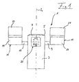
- Figure 1 illustrates a range 1 comprising a support of the column type 3, which is fixedly placed on the ground (not shown in more detail) by providing electrical connections and / or other connections.
- a heating plate 7 is arranged at optimum height ergonomically for the user.
- the cooker 1 generally comprises a shaft-type support structure, in which two branch-type pivot axes 9, 11 extend perpendicularly to the longitudinal axis L of the support 3.
- a module 13, 15 is disposed respectively left side and right side on the support 3.
- the cooking modules 13, 15 are pivotally housed, in order to spill cooking or cleaning liquids over a limiting ridge of the cooking module 13, 15.
- a corresponding drive unit is arranged in the support of the column type 3.
- the cooking modules 13, 15 respectively comprise a tank 17, 19, which can be closed by a movable cover 21, 23.
- a display system 25 according to the invention is integrated at the height of the pivot axis on the support of the column type 3, which system consists of several touch screen control panels and display units and is combined to a joystick, like a turning knob.
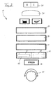
- Figure 2 is shown a detailed view of the display control panel of the display system 25 according to the invention.
- the display system 25 of the invention includes a plurality of visual display panels, which are combined with a control function, which is generally referred to as a touch screen.
- the rectangular top panel 31 is used to turn on and off a selected cooking module. We will come back later to the individual selection.
- the operating state of the cooking module is designated “0" when it is off and "I” when it is activated.
- the control panel 33 located below is used to select a memorized cooking function defined, the location and selection being made by touching the control panel.
- the two smaller pictograms represent displays according to which the selected cooking module is in roasting or steaming and / or boiling activity.
- Predefined cooking procedures can be set with the control panel bar 37, 39, 41 arranged below.
- baking procedures for roasting processes for example the rissolement of pieces of meat, fish, etc.
- steaming processes for example for braising or cooking boiled eggs or pasta, being provided in a left part of the bar of the control panel.
- Pictograms (not shown) can be used for visual representation of individual cooking programs.
- the display system according to the invention further comprises a correspondence display 43, which indicates, by an arrow lighting and extinguishing, to which cooking modules 13, 15 must correspond the operating values in the panels of display 33, 37, 39, 41 cited above.
- the correspondence display 43 may be provided with a color display (not shown), which may uniformly display one or more hues. For example, in a left section of panel 45, the bottom is of a red color, which makes it clear to the user that the left side cooking module 15 is in cooking activity. If the straight section of panel 45 of the correspondence display 43 is also red, the user must deduce that the right cooking module 13 is also in operation. In the case of another color, the user can deduce that the respective cooking module is stopped.
- the display system 25 is equipped with an acoustic signal emitter (not shown), which emits in particular an acoustic signal when a defined value of the operating state on the unselected cooking module is set or when the operating state of the cooking module unselected is changed.
- an acoustic signal emitter (not shown), which emits in particular an acoustic signal when a defined value of the operating state on the unselected cooking module is set or when the operating state of the cooking module unselected is changed.
- a touch screen function is integrated in the correspondence display 43, to easily select the respective cooking module 13, 15. By touching the respective panel section 45, 47, the left or right cooking module 13, 15 can be selected.
- a program selection push button 49 is arranged below the correspondence display 43, a button with which different cooking programs can be selected, which can be displayed for example in the display bars 37 to 41.
- an induction regulator 51 is provided below the switch 49.
Landscapes
- Engineering & Computer Science (AREA)
- Chemical & Material Sciences (AREA)
- Combustion & Propulsion (AREA)
- Mechanical Engineering (AREA)
- General Engineering & Computer Science (AREA)
- Electric Ovens (AREA)
- Induction Heating Cooking Devices (AREA)
- Electric Stoves And Ranges (AREA)
- Cookers (AREA)
- Indicating Measured Values (AREA)
Applications Claiming Priority (1)
| Application Number | Priority Date | Filing Date | Title |
|---|---|---|---|
| FR0504126A FR2884903B1 (fr) | 2005-04-25 | 2005-04-25 | Systeme d'affichage de l'etat de fonctionnement d'un parmi plusieurs modules de cuisson comme une cuve, d'une cuisiniere |
Publications (3)
| Publication Number | Publication Date |
|---|---|
| EP1719952A2 true EP1719952A2 (de) | 2006-11-08 |
| EP1719952A3 EP1719952A3 (de) | 2008-02-20 |
| EP1719952B1 EP1719952B1 (de) | 2018-01-17 |
Family
ID=35432260
Family Applications (1)
| Application Number | Title | Priority Date | Filing Date |
|---|---|---|---|
| EP06008243.5A Expired - Lifetime EP1719952B1 (de) | 2005-04-25 | 2006-04-21 | Gargerät mit mehreren Kochmodulen und eine Betriebszustandsanzeigeeinrichtung |
Country Status (2)
| Country | Link |
|---|---|
| EP (1) | EP1719952B1 (de) |
| FR (1) | FR2884903B1 (de) |
Cited By (8)
| Publication number | Priority date | Publication date | Assignee | Title |
|---|---|---|---|---|
| WO2009026877A3 (de) * | 2007-08-27 | 2010-01-21 | Rational Ag | Produkt- und sprachenunabhängige, graphische anzeige- und bedieneinrichtung eines gargeräts und gargerät hierfür |
| EP2211117A1 (de) | 2009-01-27 | 2010-07-28 | Rational AG | Verfahren zur Auswahl und Anordnung von Programm-Repräsentanten und Gargerät hierfür |
| EP2211115A2 (de) | 2009-01-27 | 2010-07-28 | Rational AG | Verfahren zur Anordnung von Programmen |
| EP2211114A2 (de) | 2009-01-27 | 2010-07-28 | Rational AG | Verfahren zur Anordnung von Programmen und Gargerät hierfür |
| EP2211116A1 (de) | 2009-01-27 | 2010-07-28 | Rational AG | Verfahren zur Visualisierung von Programmen und Gargerät hierfür |
| EP2261568A1 (de) * | 2009-06-12 | 2010-12-15 | Electrolux Home Products Corporation N.V. | Bedieneinrichtung für Küchengerät |
| EP2583600A1 (de) | 2011-10-19 | 2013-04-24 | MKN Maschinenfabrik Kurt Neubauer GmbH & Co. | Gargerät mit mehreren Garräumen und Verfahren zur Steuerung eines solchen Gerätes |
| EP2695552A1 (de) * | 2012-08-10 | 2014-02-12 | Frima-T Sas | Gargerät |
Citations (2)
| Publication number | Priority date | Publication date | Assignee | Title |
|---|---|---|---|---|
| EP1254623A2 (de) | 2001-04-30 | 2002-11-06 | Rational AG | Garmodulsystem |
| DE10127594A1 (de) | 2001-05-30 | 2002-12-05 | Ego Elektro Geraetebau Gmbh | Berührungsschalteranordnung für ein Elektrogerät |
Family Cites Families (9)
| Publication number | Priority date | Publication date | Assignee | Title |
|---|---|---|---|---|
| US4454501A (en) * | 1980-07-25 | 1984-06-12 | Roper Corporation | Prompting control |
| FR2522785A1 (fr) * | 1982-03-05 | 1983-09-09 | Scholtes Ets Eugen | Tableau de commande d'appareil de cuisson menager a programmation electronique |
| ATE344426T1 (de) * | 1998-10-01 | 2006-11-15 | Aeg Hausgeraete Gmbh | Kochfeld mit integrierter zeitsteuerung |
| US6255630B1 (en) * | 1999-09-01 | 2001-07-03 | Maytag Corporation | Program control and display system for a cooking appliance |
| JP4474573B2 (ja) * | 2000-07-14 | 2010-06-09 | パロマ工業株式会社 | フライヤー |
| DE20203117U1 (de) * | 2002-02-22 | 2002-05-23 | Wiesheu Gmbh, 71563 Affalterbach | Vorrichtung zur Wärmebehandlung von Lebensmitteln |
| FR2856574B1 (fr) * | 2003-06-30 | 2005-10-14 | Frima Sa | Agencement de modules de cuisson |
| DE202004018719U1 (de) * | 2004-01-07 | 2005-04-21 | Rational Ag | Bedienelement für ein Gargerät |
| DE102005032088A1 (de) * | 2005-07-08 | 2007-01-18 | BSH Bosch und Siemens Hausgeräte GmbH | Hausgerät, insbesondere Gargerät mit berührungsempfindlichem Stellstreifen |
-
2005
- 2005-04-25 FR FR0504126A patent/FR2884903B1/fr not_active Expired - Lifetime
-
2006
- 2006-04-21 EP EP06008243.5A patent/EP1719952B1/de not_active Expired - Lifetime
Patent Citations (2)
| Publication number | Priority date | Publication date | Assignee | Title |
|---|---|---|---|---|
| EP1254623A2 (de) | 2001-04-30 | 2002-11-06 | Rational AG | Garmodulsystem |
| DE10127594A1 (de) | 2001-05-30 | 2002-12-05 | Ego Elektro Geraetebau Gmbh | Berührungsschalteranordnung für ein Elektrogerät |
Cited By (16)
| Publication number | Priority date | Publication date | Assignee | Title |
|---|---|---|---|---|
| WO2009026877A3 (de) * | 2007-08-27 | 2010-01-21 | Rational Ag | Produkt- und sprachenunabhängige, graphische anzeige- und bedieneinrichtung eines gargeräts und gargerät hierfür |
| EP2211114A3 (de) * | 2009-01-27 | 2011-12-07 | Rational AG | Verfahren zur Anordnung von Programmen und Gargerät hierfür |
| EP2211117A1 (de) | 2009-01-27 | 2010-07-28 | Rational AG | Verfahren zur Auswahl und Anordnung von Programm-Repräsentanten und Gargerät hierfür |
| EP2211115A2 (de) | 2009-01-27 | 2010-07-28 | Rational AG | Verfahren zur Anordnung von Programmen |
| EP2211114A2 (de) | 2009-01-27 | 2010-07-28 | Rational AG | Verfahren zur Anordnung von Programmen und Gargerät hierfür |
| EP2211116A1 (de) | 2009-01-27 | 2010-07-28 | Rational AG | Verfahren zur Visualisierung von Programmen und Gargerät hierfür |
| DE102009006224A1 (de) | 2009-01-27 | 2010-07-29 | Rational Ag | Verfahren zur Auswahl und Anordnung von Programmen, Gargerät hierfür und Küchennetzwerk hiermit |
| DE102009006182A1 (de) | 2009-01-27 | 2010-07-29 | Rational Ag | Verfahren zur Auswahl und Anordnung von Programmen, Gargerät hierfür und Küchennetzwerk hiermit |
| EP2211115A3 (de) * | 2009-01-27 | 2011-12-07 | Rational AG | Verfahren zur Anordnung von Programmen |
| WO2010142542A3 (en) * | 2009-06-12 | 2011-03-31 | Electrolux Home Products Corporation N.V. | Control device for kitchen appliance |
| EP2261568A1 (de) * | 2009-06-12 | 2010-12-15 | Electrolux Home Products Corporation N.V. | Bedieneinrichtung für Küchengerät |
| CN102803854A (zh) * | 2009-06-12 | 2012-11-28 | 伊莱克斯家用产品股份有限公司 | 用于厨房用具的控制装置 |
| AU2010257658B2 (en) * | 2009-06-12 | 2015-03-05 | Electrolux Home Products Corporation N.V. | Control device for kitchen appliance |
| CN102803854B (zh) * | 2009-06-12 | 2015-09-02 | 伊莱克斯家用产品股份有限公司 | 用于厨房用具的控制装置 |
| EP2583600A1 (de) | 2011-10-19 | 2013-04-24 | MKN Maschinenfabrik Kurt Neubauer GmbH & Co. | Gargerät mit mehreren Garräumen und Verfahren zur Steuerung eines solchen Gerätes |
| EP2695552A1 (de) * | 2012-08-10 | 2014-02-12 | Frima-T Sas | Gargerät |
Also Published As
| Publication number | Publication date |
|---|---|
| EP1719952A3 (de) | 2008-02-20 |
| FR2884903A1 (fr) | 2006-10-27 |
| FR2884903B1 (fr) | 2007-10-05 |
| EP1719952B1 (de) | 2018-01-17 |
Similar Documents
| Publication | Publication Date | Title |
|---|---|---|
| RU2387361C2 (ru) | Панель управления автомата для приготовления горячих напитков и автомат, содержащий такую панель управления | |
| US9750089B2 (en) | Cooking device with a predetermined parameter, program and/or mode of operation | |
| US10260754B2 (en) | Advanced electronic control display | |
| EP1719952B1 (de) | Gargerät mit mehreren Kochmodulen und eine Betriebszustandsanzeigeeinrichtung | |
| US20080218486A1 (en) | Contextual Touch Panel | |
| FR2993431A1 (fr) | Machine agricole a systeme perfectionne d'affichage de parametres fonctionnels | |
| JP2009288451A (ja) | 商品情報表示システム | |
| US20170295997A1 (en) | Capacitive touch faceplate for a blender | |
| JP2017006550A (ja) | 調理器の表示装置 | |
| JP2003262345A (ja) | 加熱調理器 | |
| US7008022B2 (en) | Lever arm with tactile contour | |
| JP2018132200A (ja) | コンロおよび調理支援システム | |
| EP3273834B1 (de) | Mit einer verbesserten anzeige ausgestattete vorrichtung zur verwaltung des kochens | |
| JP6110733B2 (ja) | 加熱調理装置 | |
| JP2007060917A (ja) | 調理用食品 | |
| EP2291623A1 (de) | Waage mit interaktiver schnittstelle | |
| JP4879564B2 (ja) | 加熱調理器 | |
| JP3116243U (ja) | 調理用食品 | |
| WO2001015011B1 (en) | Methods and devices for selecting data files | |
| JP2006126379A (ja) | 多機能画像表示装置 | |
| EP2402660B1 (de) | Vorrichtung zur Steuerung eines Haushaltsgeräts | |
| JP2025184227A (ja) | 炊飯器 | |
| KR101312133B1 (ko) | 온도표시용 집게 | |
| JP2019000286A (ja) | 調理器の表示装置 | |
| JPH1114066A (ja) | 加熱調理器 |
Legal Events
| Date | Code | Title | Description |
|---|---|---|---|
| PUAI | Public reference made under article 153(3) epc to a published international application that has entered the european phase |
Free format text: ORIGINAL CODE: 0009012 |
|
| AK | Designated contracting states |
Kind code of ref document: A2 Designated state(s): AT BE BG CH CY CZ DE DK EE ES FI FR GB GR HU IE IS IT LI LT LU LV MC NL PL PT RO SE SI SK TR |
|
| AX | Request for extension of the european patent |
Extension state: AL BA HR MK YU |
|
| PUAL | Search report despatched |
Free format text: ORIGINAL CODE: 0009013 |
|
| AK | Designated contracting states |
Kind code of ref document: A3 Designated state(s): AT BE BG CH CY CZ DE DK EE ES FI FR GB GR HU IE IS IT LI LT LU LV MC NL PL PT RO SE SI SK TR |
|
| AX | Request for extension of the european patent |
Extension state: AL BA HR MK YU |
|
| 17P | Request for examination filed |
Effective date: 20080325 |
|
| AKX | Designation fees paid |
Designated state(s): DE FR GB IT |
|
| 17Q | First examination report despatched |
Effective date: 20090526 |
|
| RAP1 | Party data changed (applicant data changed or rights of an application transferred) |
Owner name: RATIONAL AG Owner name: FRIMA T SAS |
|
| RAP1 | Party data changed (applicant data changed or rights of an application transferred) |
Owner name: FRIMA INTERNATIONAL AG Owner name: RATIONAL AG |
|
| GRAP | Despatch of communication of intention to grant a patent |
Free format text: ORIGINAL CODE: EPIDOSNIGR1 |
|
| INTG | Intention to grant announced |
Effective date: 20170920 |
|
| GRAS | Grant fee paid |
Free format text: ORIGINAL CODE: EPIDOSNIGR3 |
|
| GRAA | (expected) grant |
Free format text: ORIGINAL CODE: 0009210 |
|
| AK | Designated contracting states |
Kind code of ref document: B1 Designated state(s): DE FR GB IT |
|
| REG | Reference to a national code |
Ref country code: GB Ref legal event code: FG4D Free format text: NOT ENGLISH |
|
| REG | Reference to a national code |
Ref country code: DE Ref legal event code: R096 Ref document number: 602006054562 Country of ref document: DE |
|
| REG | Reference to a national code |
Ref country code: FR Ref legal event code: PLFP Year of fee payment: 13 |
|
| REG | Reference to a national code |
Ref country code: DE Ref legal event code: R097 Ref document number: 602006054562 Country of ref document: DE |
|
| PLBE | No opposition filed within time limit |
Free format text: ORIGINAL CODE: 0009261 |
|
| STAA | Information on the status of an ep patent application or granted ep patent |
Free format text: STATUS: NO OPPOSITION FILED WITHIN TIME LIMIT |
|
| 26N | No opposition filed |
Effective date: 20181018 |
|
| GBPC | Gb: european patent ceased through non-payment of renewal fee |
Effective date: 20180421 |
|
| PG25 | Lapsed in a contracting state [announced via postgrant information from national office to epo] |
Ref country code: GB Free format text: LAPSE BECAUSE OF NON-PAYMENT OF DUE FEES Effective date: 20180421 |
|
| P01 | Opt-out of the competence of the unified patent court (upc) registered |
Effective date: 20230619 |
|
| REG | Reference to a national code |
Ref country code: DE Ref legal event code: R084 Ref document number: 602006054562 Country of ref document: DE |
|
| REG | Reference to a national code |
Ref country code: DE Ref legal event code: R081 Ref document number: 602006054562 Country of ref document: DE Owner name: RATIONAL INTERNATIONAL AG, CH Free format text: FORMER OWNERS: FRIMA INTERNATIONAL AG, HEERBRUGG, CH; RATIONAL AG, 86899 LANDSBERG, DE Ref country code: DE Ref legal event code: R081 Ref document number: 602006054562 Country of ref document: DE Owner name: RATIONAL AG, DE Free format text: FORMER OWNERS: FRIMA INTERNATIONAL AG, HEERBRUGG, CH; RATIONAL AG, 86899 LANDSBERG, DE |
|
| PGFP | Annual fee paid to national office [announced via postgrant information from national office to epo] |
Ref country code: DE Payment date: 20250417 Year of fee payment: 20 |
|
| PGFP | Annual fee paid to national office [announced via postgrant information from national office to epo] |
Ref country code: IT Payment date: 20250430 Year of fee payment: 20 |
|
| PGFP | Annual fee paid to national office [announced via postgrant information from national office to epo] |
Ref country code: FR Payment date: 20250424 Year of fee payment: 20 |
|
| REG | Reference to a national code |
Ref country code: DE Ref legal event code: R071 Ref document number: 602006054562 Country of ref document: DE |