EP2693274B1 - Conductive member - Google Patents
Conductive member Download PDFInfo
- Publication number
- EP2693274B1 EP2693274B1 EP12765709.6A EP12765709A EP2693274B1 EP 2693274 B1 EP2693274 B1 EP 2693274B1 EP 12765709 A EP12765709 A EP 12765709A EP 2693274 B1 EP2693274 B1 EP 2693274B1
- Authority
- EP
- European Patent Office
- Prior art keywords
- conductive
- conductive layer
- epichlorohydrin rubber
- charging roller
- evaluation
- Prior art date
- Legal status (The legal status is an assumption and is not a legal conclusion. Google has not performed a legal analysis and makes no representation as to the accuracy of the status listed.)
- Active
Links
Images

Classifications
-
- G—PHYSICS
- G03—PHOTOGRAPHY; CINEMATOGRAPHY; ANALOGOUS TECHNIQUES USING WAVES OTHER THAN OPTICAL WAVES; ELECTROGRAPHY; HOLOGRAPHY
- G03G—ELECTROGRAPHY; ELECTROPHOTOGRAPHY; MAGNETOGRAPHY
- G03G15/00—Apparatus for electrographic processes using a charge pattern
- G03G15/02—Apparatus for electrographic processes using a charge pattern for laying down a uniform charge, e.g. for sensitising; Corona discharge devices
- G03G15/0208—Apparatus for electrographic processes using a charge pattern for laying down a uniform charge, e.g. for sensitising; Corona discharge devices by contact, friction or induction, e.g. liquid charging apparatus
- G03G15/0216—Apparatus for electrographic processes using a charge pattern for laying down a uniform charge, e.g. for sensitising; Corona discharge devices by contact, friction or induction, e.g. liquid charging apparatus by bringing a charging member into contact with the member to be charged, e.g. roller, brush chargers
- G03G15/0233—Structure, details of the charging member, e.g. chemical composition, surface properties
-
- B—PERFORMING OPERATIONS; TRANSPORTING
- B32—LAYERED PRODUCTS
- B32B—LAYERED PRODUCTS, i.e. PRODUCTS BUILT-UP OF STRATA OF FLAT OR NON-FLAT, e.g. CELLULAR OR HONEYCOMB, FORM
- B32B1/00—Layered products having a non-planar shape
- B32B1/08—Tubular products
-
- B—PERFORMING OPERATIONS; TRANSPORTING
- B32—LAYERED PRODUCTS
- B32B—LAYERED PRODUCTS, i.e. PRODUCTS BUILT-UP OF STRATA OF FLAT OR NON-FLAT, e.g. CELLULAR OR HONEYCOMB, FORM
- B32B15/00—Layered products comprising a layer of metal
- B32B15/04—Layered products comprising a layer of metal comprising metal as the main or only constituent of a layer, which is next to another layer of the same or of a different material
- B32B15/06—Layered products comprising a layer of metal comprising metal as the main or only constituent of a layer, which is next to another layer of the same or of a different material of natural rubber or synthetic rubber
-
- B—PERFORMING OPERATIONS; TRANSPORTING
- B32—LAYERED PRODUCTS
- B32B—LAYERED PRODUCTS, i.e. PRODUCTS BUILT-UP OF STRATA OF FLAT OR NON-FLAT, e.g. CELLULAR OR HONEYCOMB, FORM
- B32B15/00—Layered products comprising a layer of metal
- B32B15/18—Layered products comprising a layer of metal comprising iron or steel
-
- B—PERFORMING OPERATIONS; TRANSPORTING
- B32—LAYERED PRODUCTS
- B32B—LAYERED PRODUCTS, i.e. PRODUCTS BUILT-UP OF STRATA OF FLAT OR NON-FLAT, e.g. CELLULAR OR HONEYCOMB, FORM
- B32B25/00—Layered products comprising a layer of natural or synthetic rubber
- B32B25/02—Layered products comprising a layer of natural or synthetic rubber with fibres or particles being present as additives in the layer
-
- B—PERFORMING OPERATIONS; TRANSPORTING
- B32—LAYERED PRODUCTS
- B32B—LAYERED PRODUCTS, i.e. PRODUCTS BUILT-UP OF STRATA OF FLAT OR NON-FLAT, e.g. CELLULAR OR HONEYCOMB, FORM
- B32B25/00—Layered products comprising a layer of natural or synthetic rubber
- B32B25/14—Layered products comprising a layer of natural or synthetic rubber comprising synthetic rubber copolymers
-
- C—CHEMISTRY; METALLURGY
- C08—ORGANIC MACROMOLECULAR COMPOUNDS; THEIR PREPARATION OR CHEMICAL WORKING-UP; COMPOSITIONS BASED THEREON
- C08G—MACROMOLECULAR COMPOUNDS OBTAINED OTHERWISE THAN BY REACTIONS ONLY INVOLVING UNSATURATED CARBON-TO-CARBON BONDS
- C08G65/00—Macromolecular compounds obtained by reactions forming an ether link in the main chain of the macromolecule
- C08G65/02—Macromolecular compounds obtained by reactions forming an ether link in the main chain of the macromolecule from cyclic ethers by opening of the heterocyclic ring
- C08G65/32—Polymers modified by chemical after-treatment
- C08G65/329—Polymers modified by chemical after-treatment with organic compounds
- C08G65/333—Polymers modified by chemical after-treatment with organic compounds containing nitrogen
- C08G65/33303—Polymers modified by chemical after-treatment with organic compounds containing nitrogen containing amino group
-
- C—CHEMISTRY; METALLURGY
- C08—ORGANIC MACROMOLECULAR COMPOUNDS; THEIR PREPARATION OR CHEMICAL WORKING-UP; COMPOSITIONS BASED THEREON
- C08L—COMPOSITIONS OF MACROMOLECULAR COMPOUNDS
- C08L71/00—Compositions of polyethers obtained by reactions forming an ether link in the main chain; Compositions of derivatives of such polymers
- C08L71/02—Polyalkylene oxides
- C08L71/03—Polyepihalohydrins
-
- G—PHYSICS
- G03—PHOTOGRAPHY; CINEMATOGRAPHY; ANALOGOUS TECHNIQUES USING WAVES OTHER THAN OPTICAL WAVES; ELECTROGRAPHY; HOLOGRAPHY
- G03G—ELECTROGRAPHY; ELECTROPHOTOGRAPHY; MAGNETOGRAPHY
- G03G15/00—Apparatus for electrographic processes using a charge pattern
- G03G15/06—Apparatus for electrographic processes using a charge pattern for developing
- G03G15/08—Apparatus for electrographic processes using a charge pattern for developing using a solid developer, e.g. powder developer
- G03G15/0806—Apparatus for electrographic processes using a charge pattern for developing using a solid developer, e.g. powder developer on a donor element, e.g. belt, roller
- G03G15/0808—Apparatus for electrographic processes using a charge pattern for developing using a solid developer, e.g. powder developer on a donor element, e.g. belt, roller characterised by the developer supplying means, e.g. structure of developer supply roller
-
- G—PHYSICS
- G03—PHOTOGRAPHY; CINEMATOGRAPHY; ANALOGOUS TECHNIQUES USING WAVES OTHER THAN OPTICAL WAVES; ELECTROGRAPHY; HOLOGRAPHY
- G03G—ELECTROGRAPHY; ELECTROPHOTOGRAPHY; MAGNETOGRAPHY
- G03G15/00—Apparatus for electrographic processes using a charge pattern
- G03G15/06—Apparatus for electrographic processes using a charge pattern for developing
- G03G15/08—Apparatus for electrographic processes using a charge pattern for developing using a solid developer, e.g. powder developer
- G03G15/0806—Apparatus for electrographic processes using a charge pattern for developing using a solid developer, e.g. powder developer on a donor element, e.g. belt, roller
- G03G15/0818—Apparatus for electrographic processes using a charge pattern for developing using a solid developer, e.g. powder developer on a donor element, e.g. belt, roller characterised by the structure of the donor member, e.g. surface properties
-
- G—PHYSICS
- G03—PHOTOGRAPHY; CINEMATOGRAPHY; ANALOGOUS TECHNIQUES USING WAVES OTHER THAN OPTICAL WAVES; ELECTROGRAPHY; HOLOGRAPHY
- G03G—ELECTROGRAPHY; ELECTROPHOTOGRAPHY; MAGNETOGRAPHY
- G03G15/00—Apparatus for electrographic processes using a charge pattern
- G03G15/14—Apparatus for electrographic processes using a charge pattern for transferring a pattern to a second base
- G03G15/16—Apparatus for electrographic processes using a charge pattern for transferring a pattern to a second base of a toner pattern, e.g. a powder pattern, e.g. magnetic transfer
- G03G15/1665—Apparatus for electrographic processes using a charge pattern for transferring a pattern to a second base of a toner pattern, e.g. a powder pattern, e.g. magnetic transfer by introducing the second base in the nip formed by the recording member and at least one transfer member, e.g. in combination with bias or heat
- G03G15/167—Apparatus for electrographic processes using a charge pattern for transferring a pattern to a second base of a toner pattern, e.g. a powder pattern, e.g. magnetic transfer by introducing the second base in the nip formed by the recording member and at least one transfer member, e.g. in combination with bias or heat at least one of the recording member or the transfer member being rotatable during the transfer
- G03G15/1685—Structure, details of the transfer member, e.g. chemical composition
-
- B—PERFORMING OPERATIONS; TRANSPORTING
- B32—LAYERED PRODUCTS
- B32B—LAYERED PRODUCTS, i.e. PRODUCTS BUILT-UP OF STRATA OF FLAT OR NON-FLAT, e.g. CELLULAR OR HONEYCOMB, FORM
- B32B2264/00—Composition or properties of particles which form a particulate layer or are present as additives
- B32B2264/10—Inorganic particles
- B32B2264/104—Oxysalt, e.g. carbonate, sulfate, phosphate or nitrate particles
-
- B—PERFORMING OPERATIONS; TRANSPORTING
- B32—LAYERED PRODUCTS
- B32B—LAYERED PRODUCTS, i.e. PRODUCTS BUILT-UP OF STRATA OF FLAT OR NON-FLAT, e.g. CELLULAR OR HONEYCOMB, FORM
- B32B2264/00—Composition or properties of particles which form a particulate layer or are present as additives
- B32B2264/10—Inorganic particles
- B32B2264/107—Ceramic
- B32B2264/108—Carbon, e.g. graphite particles
-
- B—PERFORMING OPERATIONS; TRANSPORTING
- B32—LAYERED PRODUCTS
- B32B—LAYERED PRODUCTS, i.e. PRODUCTS BUILT-UP OF STRATA OF FLAT OR NON-FLAT, e.g. CELLULAR OR HONEYCOMB, FORM
- B32B2307/00—Properties of the layers or laminate
- B32B2307/20—Properties of the layers or laminate having particular electrical or magnetic properties, e.g. piezoelectric
- B32B2307/202—Conductive
-
- B—PERFORMING OPERATIONS; TRANSPORTING
- B32—LAYERED PRODUCTS
- B32B—LAYERED PRODUCTS, i.e. PRODUCTS BUILT-UP OF STRATA OF FLAT OR NON-FLAT, e.g. CELLULAR OR HONEYCOMB, FORM
- B32B2457/00—Electrical equipment
-
- Y—GENERAL TAGGING OF NEW TECHNOLOGICAL DEVELOPMENTS; GENERAL TAGGING OF CROSS-SECTIONAL TECHNOLOGIES SPANNING OVER SEVERAL SECTIONS OF THE IPC; TECHNICAL SUBJECTS COVERED BY FORMER USPC CROSS-REFERENCE ART COLLECTIONS [XRACs] AND DIGESTS
- Y10—TECHNICAL SUBJECTS COVERED BY FORMER USPC
- Y10T—TECHNICAL SUBJECTS COVERED BY FORMER US CLASSIFICATION
- Y10T428/00—Stock material or miscellaneous articles
- Y10T428/31504—Composite [nonstructural laminate]
- Y10T428/31855—Of addition polymer from unsaturated monomers
Definitions
- the present invention relates to a conductive member to be used in an electrophotographic image-forming apparatus.
- a conductive member including a conductive layer obtained by adding an ionic conductive agent to a polar polymer such as a hydrin rubber to adjust its electrical resistance value has been proposed as such a conductive member that unevenness in its electrical resistance value has been alleviated.
- the ionic conductive agent when used, the ionic conductive agent may be unevenly distributed (localized) in the conductive layer owing to long-term use of the member. Possible causes for the foregoing are as described below.
- the time period for which a DC voltage is applied to the conductive member at the time of its use is long.
- an ion exchange group of the ionic conductive agent undergoes ionic dissociation, and hence an anion and a cation move in the conductive layer to be unevenly distributed.
- the uneven distribution of the ion exchange group in the conductive layer increases the electrical resistance value of the conductive member.
- the long-term application of the DC potential to the conductive member and the repeated application of the stress to the conductive layer prompt the bleedout of a low-molecular weight component in the conductive member toward the surface of the conductive layer.
- the bleedout of the low-molecular weight component toward the surface of the conductive layer leads to the contamination of the surface of a photosensitive member.
- Patent Literature 1 a specific quaternary ammonium salt capable of reducing the electrical resistance value even when added in a small amount is used as an ionic conductive agent.
- Patent Literature 2 the bleeding and blooming of an ionic conductive agent are suppressed by using a quaternary ammonium salt having an OH group.
- the present invention is directed to providing a conductive member whose electrical resistance value hardly changes even after its long-term use.
- a conductive member including: a conductive support; and a conductive layer, in which the conductive layer contains a modified epichlorohydrin rubber having a unit represented by the following formula (1) and an anion.
- R1, R2, and R3 each independently represent hydrogen or a saturated hydrocarbon group having 1 to 18 carbon atoms.
- a process cartridge which is attachably/detachably mounted to a main body of an electrophotographic apparatus, the process cartridge including the above-mentioned conductive member as at least one member selected from a charging member and a developing member.
- an electrophotographic apparatus including the above-mentioned conductive member as at least one member selected from a charging member and a developing member.
- FIG. 1 is a schematic construction view of a conductive member according to the present invention.
- the outer periphery of a conductive support 11 is provided with a conductive layer 12.
- the conductive layer 12 may have a multilayer structure including two or more layers.
- the conductive member according to the present invention can be used as a charging member (charging roller), a developing member (developing roller), a transferring member (transfer roller), an antistatic member, or a conveying member such as a sheet-feeding roller in an electrophotographic image-forming apparatus.
- the conductive member is suitable for a conductive member to be stationarily energized such as a charging blade or a transferring pad.
- the present invention is described by way of a charging roller, a developing roller, or the like as a representative example of the conductive member.
- the conductive support has conductivity for feeding the surface of a charging roller through the support.
- the conductive support is, for example, a column obtained by plating the surface of a carbon steel alloy with nickel having a thickness of about 5 ⁇ m.
- Metals such as iron, aluminum, titanium, copper, and nickel, alloys containing these metals such as stainless steel, duralumin, brass, and bronze, and composite materials obtained by hardening carbon black or carbon fibers with plastic can be given as examples of any other material for constituting the conductive support.
- a known material that is rigid and shows conductivity can be used.
- the shape can be a cylindrical shape whose central portion has been hollowed out as well as the columnar shape.
- the conductive layer contains a modified epichlorohydrin rubber having a unit represented by the following formula (1) and an anion.
- R1, R2, and R3 each independently represent hydrogen or a saturated hydrocarbon group having 1 to 18 carbon atoms.
- An epichlorohydrin rubber which is a raw material for the modified epichlorohydrin rubber according to the present invention, is a general term for rubbers each having a unit derived from epichlorohydrin represented by the following formula (2).
- the epichlorohydrin rubber examples include a homopolymer formed of the unit represented by the formula (2) alone, an epichlorohydrin-alkylene oxide copolymer formed of the unit represented by the formula (2) and an alkylene oxide unit represented by the following formula (3), and further, an epichlorohydrin-alkylene oxide-allyl glycidyl ether terpolymer having a unit derived from allyl glycidyl ether represented by the following formula (4) in addition to the units represented by the formula (2) and the formula (3).
- n an integer of 1 to 3.
- the terpolymer having the units represented by the formula (2), the formula (3), and the formula (4) is suitably used as the modified epichlorohydrin rubber according to the present invention because its vulcanization rate and vulcanization density can be easily adjusted by virtue of the presence of a double bond portion in the unit derived from allyl glycidyl ether.
- the electrical resistance value of the epichlorohydrin rubber having the units represented by the formula (2) to the formula (4) and the extent of the variation of the electrical resistance value caused by a temperature/humidity environment can be controlled depending on the molar ratio of each unit.
- the molar ratios of the unit derived from epichlorohydrin, the unit represented by the formula (3), and the unit derived from allyl glycidyl ether are, for example, 19 mol% or more and 75 mol% or less, 24 mol% or more and 80 mol% or less, and 1 mol% or more and 15 mol% or less, respectively.
- More preferred molar ratios of the unit derived from epichlorohydrin, the unit represented by the formula (3), and the unit derived from allyl glycidyl ether are 19 mol% or more and 45 mol% or less, 50 mol% or more and 80 mol% or less, and 1 mol% or more and 10 mol% or less, respectively.
- the electrical resistance value can be reduced and the variation of the electrical resistance value caused by the temperature/humidity environment can be suppressed.
- the modified epichlorohydrin rubber according to the present invention is such that at least one unit of the units derived from epichlorohydrin in the epichlorohydrin rubber is the unit represented by the formula (1). That is, the modified epichlorohydrin rubber according to the present invention has a quaternary ammonium ion chemically bonded in a molecule thereof.
- a conductive layer expresses its ionic conductivity as a result of the movement of an anion, which is a carrier molecule present in the conductive layer, in the conductive layer.
- the quaternary ammonium ion as a cation is chemically bonded to the modified epichlorohydrin rubber as a binder for the conductive layer, and hence excessive movement of an anion as a carrier ion in the conductive layer is suppressed.
- the exudation (bleeding) of an ionic conductive component from the inside of the conductive layer toward its surface is suppressed.
- R1, R2, and R3 each independently represent hydrogen or a saturated hydrocarbon group having 1 or more and 18 or less carbon atoms, particularly preferably a saturated hydrocarbon group having 1 or more and 8 or less carbon atoms.
- the number of carbon atoms of the saturated hydrocarbon group is excessively large, the ion exchange ability of an amine compound per unit mass reduces owing to an increase in its molecular weight in association with an increase in number of carbon atoms. As a result, conductivity required for the conductive layer is hardly obtained.
- the modified epichlorohydrin rubber having the unit represented by the formula (1) can be obtained by dechlorinating a chlorine atom in an alkylene chloride site in a unit of an unmodified epichlorohydrin rubber through a nucleophilic substitution reaction with the amine compound. That is, a quaternary ammonium group having ionic conductivity is introduced into an epichlorohydrin rubber having excellent electrical characteristics and excellent dynamical characteristics by means of a polymer reaction, the rubber being incorporated as a binder polymer into the elastic layer of a charging member.
- an ionic conductive member having rubber elasticity can be obtained also by: polymerizing a copolymer formed of an ionic conductive monomer having an ion exchange group, and a monomer having a diene-based or crosslinkable functional group and having a glass transition temperature of 0°C or less; and crosslinking the resultant copolymer.
- a polymer of the ionic conductive monomer having an ion exchange group because the monomer generally has low polymerizability. As a result, dynamical characteristics required for a charging roller are not sufficiently obtained.
- a method for substitution with the amine compound is not particularly limited as long as the nucleophilic substitution reaction between the chlorine atom of the alkylene chloride portion which the epichlorohydrin rubber has and the amine compound progresses.
- an approach involving dissolving the epichlorohydrin rubber in an organic solvent such as dimethylformamide (DMF) by means of a solution reaction and adding the amine compound to the solution, or an approach involving adding the amine compound at the rubber kneading stage of the epichlorohydrin rubber may be employed.
- the chlorine atom of the alkylene chloride portion of the unit derived from epichlorohydrin may be substituted with a primary amine by utilizing, for example, the Delepine reaction or the Gabriel reaction.
- a vulcanization accelerator When the amine compound is added at the time of the rubber kneading, simultaneous addition of a vulcanization accelerator with the amine compound causes a reaction between the amine compound and the vulcanization accelerator, which may inhibit the nucleophilic substitution reaction with the chlorine atom of the alkylene chloride portion of the unit derived from epichlorohydrin. Accordingly, the substitution of the amine compound is preferably performed before vulcanization.
- any one of the amine compounds i.e., a primary amine, a secondary amine, and a tertiary amine can be used as the amine compound.
- an amine compound formed of a tertiary amine is preferably used because good conductivity is obtained.
- the unreacted amine compound When an unreacted amine compound that has not reacted with the chlorine atom of the alkylene chloride portion of the epichlorohydrin rubber remains in the conductive layer, there is a possibility that the compound bleeds toward the surface of the conductive layer over time. Accordingly, after the substitution reaction, the unreacted amine compound is preferably removed from the modified epichlorohydrin rubber by being vaporized through heating. Therefore, the boiling point of the amine compound is preferably 200°C or less because the removal by heating is facilitated, and is more preferably 160°C or less.
- R1, R2, and R3 in the amine compound each desirably represent a saturated hydrocarbon group having 1 or more and 18 or less carbon atoms, more preferably 1 or more and 8 or less carbon atoms.
- the anion in the conductive layer functions as a carrier molecule that moves in the conductive layer to cause the conductive layer to express its ionic conductivity.
- the kind of the anion is not particularly limited, and examples thereof include a chlorine ion, a perchlorate ion, and a bis(trifluoromethanesulfonyl)imide ion.
- the following formula (5) represents the structure of the bis(trifluoromethanesulfonyl)imide ion.
- a method of introducing a desired anion into the conductive layer is, for example, a method involving causing the desired anion to react as a counter anion with the quaternary ammonium ion which the modified epichlorohydrin rubber according to the present invention has. That is, the modified epichlorohydrin rubber obtained by introducing a quaternary ammonium base, which is formed of the desired counter anion to be incorporated into the conductive layer and the quaternary ammonium ion, into an epichlorohydrin rubber is incorporated into the conductive layer.
- the quaternary ammonium salt undergoes ionic dissociation in the conductive layer to free the counter anion, and hence the desired anion can be caused to exist in the conductive layer.
- a quaternary ammonium base having a chlorine ion as a counter ion is introduced into the epichlorohydrin rubber.
- the quaternary ammonium base undergoes ionic dissociation to free the chlorine ion as the counter ion, and hence the chlorine ion as an anion can be caused to exist in the conductive layer.
- a method of causing a perchlorate ion or the bis(trifluoromethanesulfonyl)imide ion represented by the formula (5) to exist in the conductive layer is, for example, a method involving using, as a binder in the conductive layer, a modified epichlorohydrin rubber modified with a quaternary ammonium base into which the desired anion has been introduced as a counter ion.
- the modified epichlorohydrin rubber modified with the quaternary ammonium base into which the desired anion has been introduced as a counter ion can be prepared by the following method.
- a modified epichlorohydrin rubber into which a quaternary ammonium base having a chlorine ion as a counter ion has been introduced is prepared.
- the chlorine ion of the quaternary ammonium base of the modified epichlorohydrin rubber is transformed into the desired anion by utilizing an ion exchange reaction.
- the modified epichlorohydrin rubber modified with a quaternary ammonium base into which the desired anion has been introduced as a counter ion can be obtained.
- the presence and quantitative determination of the anion as a carrier molecule in the conductive layer can be verified by the extraction of the anion by means of an ion exchange reaction.
- the modified epichlorohydrin rubber is stirred in hydrochloric acid or a dilute aqueous solution of sodium hydroxide.
- the anion in the modified epichlorohydrin rubber is extracted in the aqueous solution.
- the aqueous solution after the extraction is dried and then the extract is recovered. After that, the extract is subjected to mass spectrometry with a time-of-flight mass spectrometer (TOF-MS).
- TOF-MS time-of-flight mass spectrometer
- the anion can be analyzed in the TOF-MS measurement without being decomposed. Further, the identification and quantitative determination of the anion as a carrier molecule are additionally facilitated by performing the elemental analysis of the extract on the basis of inductively coupled plasma (ICP) emission spectrometry and combining the result of the analysis with the result of the mass spectrometry.
- ICP inductively coupled plasma
- a method of forming the conductive layer is, for example, a method involving molding a rubber composition serving as a raw material for the conductive layer by a known method such as extrusion molding, injection molding, or compression molding.
- the conductive layer may be directly formed on the conductive support, or may be formed by covering the top of the conductive support with the conductive layer molded into a tube shape in advance. It should be noted that the shape of the conductive layer is also preferably put in order by polishing its surface after the formation of the conductive layer.
- FIG. 2 is an explanatory diagram of the step of forming the conductive layer on the periphery of the conductive support by extrusion molding with a crosshead.
- the conductive supports 11 sequentially taken out of a conductive support-holding container are conveyed vertically downward without any gap by multiple pairs of conveying rollers 23 for conveying the conductive supports 11 to be introduced into a crosshead 22.
- an unvulcanized rubber composition is supplied by an extruder 21 from a direction vertical to the conveying direction of the conductive supports 11 toward the crosshead 22, and is then extruded as a covering layer covering the periphery of each of the conductive supports 11 from the crosshead 22. After that, the covering layer is cut by a cutting remover 25 to be segmented for each conductive support.
- an unvulcanized rubber roller 26 is obtained.
- the conductive layer is preferably formed into the following crown shape. Its central portion is the thickest and the layer tapers toward each of both of its end portions in order that adhesiveness between a charging roller and an electrophotographic photosensitive member may be secured.
- the charging roller that has been generally used is brought into abutment with the electrophotographic photosensitive member by applying a predetermined pressing force to each of both end portions of the support. That is, the pressing force at the central portion is small and a larger force is applied to a position as the position approaches each of both the end portions. Accordingly, no problem arises when the straightness of the charging roller is sufficient, but density unevenness may occur in images corresponding to the central portion and both the end portions when the straightness is not sufficient.
- the crown shape is formed for preventing the unevenness.
- the outer diameter runout of the charging roller is preferably as small as possible in order that an abutting nip width at the time of the rotation of the roller may be uniform.
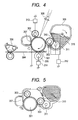
- FIG. 4 is a schematic view of an electrophotographic apparatus using the conductive member according to the present invention as a charging roller.
- the electrophotographic apparatus is constructed of members such as: a charging roller 302 for charging an electrophotographic photosensitive member 301; a latent image-forming apparatus 308 for performing exposure; a developing apparatus 303 for developing a latent image into a toner image; a transferring apparatus 305 for transferring the toner image onto a transfer material 304; a cleaning apparatus 307 for recovering transfer residual toner on the electrophotographic photosensitive member; and a fixing apparatus 306 for fixing the toner image.
- the electrophotographic photosensitive member 301 is of a rotating drum type having a photosensitive layer on a conductive base body.
- the electrophotographic photosensitive member 301 is rotationally driven in the direction indicated by an arrow at a predetermined peripheral speed (process speed).
- the charging roller 302 is placed so as to be brought into contact with the electrophotographic photosensitive member 301 by being pressed against the member with a predetermined force.
- the charging roller 302 rotates in accordance with the rotation of the electrophotographic photosensitive member 301, and charges the electrophotographic photosensitive member 301 to a predetermined potential through the application of a predetermined DC voltage from a power source 313 for charging.
- the electrophotographic photosensitive member 301 that has been uniformly charged is irradiated with light 308 corresponding to image information. Thus, an electrostatic latent image is formed.
- a developer 315 in a developer container 309 is supplied to the surface of the developing roller 303 placed so as to be brought into contact with the electrophotographic photosensitive member 301 by a developer-supplying roller 311. After that, a layer of the developer charged so as to be of the same polarity as that of the charged potential of the electrophotographic photosensitive member is formed on the surface of the developing roller 303 by a developer amount-regulating member 310.
- the electrostatic latent image formed on the electrophotographic photosensitive member is developed with the developer by reversal development.
- the transferring apparatus 305 has a contact-type transfer roller. The apparatus transfers the toner image from the electrophotographic photosensitive member 301 to the transfer material 304 such as plain paper.
- the transfer material 304 is conveyed by a sheet-feeding system having a conveying member.
- the cleaning apparatus 307 has a blade-type cleaning member and a recovery container, and mechanically scrapes off and recovers the transfer residual toner remaining on the electrophotographic photosensitive member 301 after the transfer.
- the cleaning apparatus 307 can be omitted by adopting such a simultaneous-with-development cleaning mode that the transfer residual toner is recovered in the developing apparatus 303.
- the fixing apparatus 306 is constructed of a member such as a heated roll. The apparatus fixes the transferred toner image on the transfer material 304 and then discharges the resultant to the outside of the apparatus.
- Reference numerals 312 and 314 each represent a DC power source.
- FIG. 5 is a schematic sectional view of a process cartridge obtained by applying the conductive member according to the present invention to the charging roller 302.
- the process cartridge according to the present invention is such that the electrophotographic photosensitive member 301, the charging roller 302, the developing apparatus 303, the cleaning apparatus 307, and the like are integrated, and is attachably/detachably mounted to the main body of the electrophotographic apparatus.
- EP/EO/AGE epichlorohydrin-ethylene oxide-allyl glycidyl ether
- DMF N,N-dimethylformamide
- Zinc oxide (trade name: Zinc Oxide Type 2, manufactured by Seido Chemical Industry Co., Ltd.) 5 Calcium carbonate (trade name: Silver W, manufactured by SHIRAISHI CALCIUM KAISHA, LTD.) 35 Carbon black (trade name: Seast SO, manufactured by TOKAI CARBON CO., LTD.) 8 Processing aid; stearic acid 2 Plasticizer; adipate (trade name: POLYCIZER W305ELS, manufactured by DIC) 10 Vulcanizing agent; sulfur 0.5 Crosslinking aid; dipentamethylenethiuram tetrasulfide (trade name: NOCCELER TRA, manufactured by Ouchi Shinko Chemical Industrial Co., Ltd.) 2
- a mandrel made of stainless steel having a diameter of 6 mm and a length of 258 mm was prepared and its surface was plated with nickel having a thickness of about 5 ⁇ m.
- a conductive support was obtained.
- the outer peripheral portion of the conductive support was covered with the unvulcanized rubber composition No. 1 by using the apparatus illustrated in FIG. 2 .
- the unvulcanized rubber composition of the outer peripheral portion of the conductive support was cured by being heated in a hot-air oven at a temperature of 160°C for 1 hour to be turned into a rubber layer. After that, both end portions of the rubber layer were cut.
- a conductive roller No. 1 including a rubber layer having a width of 232 mm was obtained.
- the conductive layer of the conductive roller No. 1 was ground with a wide grinder so that its central outer diameter was 8.5 mm.
- a charging roller No. 1 was obtained.
- the charging roller No. 1 was subjected to Evaluations 1 to 4 to be described below.
- the conductive layer of the charging roller No. 1 was trimmed off and then dissolved in hydrochloric acid. Thus, an anion in the conductive layer was extracted.
- the extract was recovered by evaporating water from hydrochloric acid after the extraction and was then subjected to mass spectrometry with a time-of-flight mass spectrometer (trade name: PHI TRIFT IV, manufactured by ULVAC-PHI, Inc.). Thus, the main anion species in the conductive layer was identified.
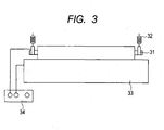
- FIG. 3 illustrates a schematic view of an electrical resistance-measuring apparatus used in this evaluation.
- the charging roller No. 1 is rotatably held by bearings 31 attached to both ends thereof and is brought into press contact with a columnar drum 33 made of aluminum having an outer diameter of 30 mm by springs 32 attached to the bearings 31 at an indentation pressure of 450 gf on each side.
- the columnar drum 33 was rotationally driven at a rotational frequency of 33 rpm to cause the charging roller No. 1 to rotate in accordance with the rotation.
- a voltage was applied from an external DC power supply 34 (trade name: Model 610E; manufactured by TReK) to the charging roller No. 1 through the drum 33 according to a constant current control mode for 305 seconds so that a DC current of 50 pA flowed.
- output voltages at an initial stage (5 seconds after a lapse of 2 seconds from the application) and after a lapse of 300 seconds (5 seconds after a lapse of 300 seconds) were measured at a sampling frequency of 100 Hz.
- the average of the output voltages at the initial stage was represented by Va (V)
- the average of the output voltages after a lapse of 300 seconds was represented by Vb (V)
- the initial voltage Va and a voltage change ratio Vb/Va were measured.
- the Va was 25.2 (V) and hence the charging roller showed good conductivity.
- the Vb/Va was 1.14 and hence the charging roller was found to show nearly no change in its electrical resistance value.
- a DC current of 300 pA was flowed through the charging roller No. 1 with the electrical resistance-measuring apparatus of Evaluation 1 for 100 minutes.
- the charging roller No. 1 was incorporated as a charging roller into a laser printer (trade name: LBP5400, manufactured by Canon Inc.) and then 1 halftone image was output.
- the halftone image was visually observed and evaluated by criteria shown in Table 2 below.
- Table 2 Rank Evaluation criterion A No image failure ascribable to the charging roller is observed.
- B An image failure ascribable to the charging roller was observed to some extent but is at a slight level.
- C An image failure ascribable to the charging roller was observed.
- the charging roller No. 1 was placed on a polyethylene terephthalate (PET) sheet under an environment having a temperature of 40°C and a humidity of 95%RH. A load of 550 gf was applied to the exposed portion of the mandrel at each of both ends of the charging roller No. 1 to press the surface of the conductive layer of the charging roller No. 1 against the PET sheet. After the state had been maintained for 1 week, the charging roller No. 1 was removed from the PET sheet and then the portion of the surface of the PET sheet against which the charging roller No. 1 had been pressed was observed with an optical microscope. A situation where a product bleeding from the conductive layer of the charging roller No. 1 adhered was observed and evaluated on the basis of criteria shown in Table 3 below. Table 3 Rank Evaluation criterion A No bleeding product is observed in the abutting portion. B Slight clouding is observed in part of the abutting portion. C A bleeding product is observed in the entire surface of the abutting portion.
- PTT polyethylene terephthalate
- Modified epichlorohydrin rubbers No. 2 to No. 12 were synthesized in the same manner as in the modified epichlorohydrin rubber No. 1 according to Example 1 except that the epichlorohydrin rubber as a raw material, the kind of amine used in the modification, and the addition amount of the amine were changed as shown in Table 4. It should be noted that an alphabetical letter for the kind of epichlorohydrin rubber as a raw material in Table 4 represents a material shown in Table 5.
- unvulcanized rubber compositions No. 2 to No. 12 were prepared in the same manner as in Example 1 except that the resultant modified epichlorohydrin rubbers No. 2 to No. 12 were used, and then charging rollers No. 2 to No. 12 were produced with the compositions.
- Modified epichlorohydrin rubbers No. 14 to No. 44 were synthesized in the same manner as in the modified epichlorohydrin rubber No. 1 according to Example 1 except that the epichlorohydrin rubber as a raw material, the kind of amine used in the modification, and the addition amount of the amine were changed as shown in Table 6.
- unvulcanized rubber compositions No. 14 to No. 44 were prepared in the same manner as in Example 1 except that the resultant modified epichlorohydrin rubbers No. 14 to No. 44 were used, and then charging rollers No. 14 to No. 44 were produced with the compositions. Those charging rollers were subjected to Evaluations 1 to 3 of Example 1. Table 6 Example Modified epichlorohydrin rubber No.
- a mandrel made of stainless steel having an outer diameter of 6 mm and a length of 258 mm was prepared and its surface was plated with nickel having a thickness of about 5 ⁇ m.
- the mandrel was set in the center of a tubular die having an inner diameter of 8.5 mm, and then the unvulcanized rubber composition No. 45 was placed between the conductive support and the die.
- the resultant was heated with a steam vulcanizer in water vapor having a temperature of 160°C for 40 minutes.
- the unvulcanized rubber composition No. 45 was subjected to primary vulcanization.
- the vulcanized product was heated in an electric oven having a temperature of 150°C for 1 hour to be turned into a rubber layer.
- Modified epichlorohydrin rubbers No. 46 and No. 47 were synthesized in the same manner as in Example 45 except that the epichlorohydrin rubber A as a raw material in Example 45 was changed to the epichlorohydrin rubber B or the epichlorohydrin rubber C shown in Table 5.
- unvulcanized rubber compositions No. 46 and No. 47 were prepared in the same manner as in Example 1 except that the resultant modified epichlorohydrin rubbers No. 46 and No. 47 were used, and then charging rollers No. 46 and No. 47 were produced with the compositions. Those charging rollers were subjected to Evaluations 1 to 3 of Example 1.
- Example 1 After the completion of the reaction, methanol was added to the reaction liquid to precipitate the reaction product. Thus, a modified epichlorohydrin rubber No. 48 was obtained.
- an unvulcanized rubber composition No. 48 was prepared in the same manner as in Example 1 except that the resultant modified epichlorohydrin rubber No. 48 was used, and then a charging roller No. 48 was produced with the composition. The charging roller was subjected to Evaluations 1 to 3 of Example 1.
- An unvulcanized rubber composition No. 50 containing a bis(trifluoromethanesulfonyl)imide ion (TFSI - ) was prepared in the same manner as in Example 49 except that 29 g of lithium bis(trifluoromethanesulfonyl)imide were used instead of lithium perchlorate of Example 49, and then a charging roller No. 50 was produced with the composition.
- the charging roller was subjected to Evaluations 1 to 3 of Example 1.
- Table 8 Material Part(s) by mass Epichlorohydrin rubber J as raw material 100
- Zinc oxide (trade name: Zinc Oxide Type 2, manufactured by Seido Chemical Industry Co., Ltd.) 5 Calcium carbonate (trade name: Silver W, manufactured by SHIRAISHI CALCIUM KAISHA, LTD.) 35 Carbon black (trade name: Seast SO, manufactured by TOKAI CARBON CO., LTD.) 8 Processing aid; stearic acid 2 Plasticizer; adipate (trade name: POLYCIZER W305ELS, manufactured by DIC) 10 Vulcanizing agent; sulfur 0.5 Crosslinking aid; dipentamethylenethiuram tetrasulfide (trade name: NOCCELER TRA, manufactured by Ouchi Shinko Chemical Industrial Co., Ltd.) 2 Tetraethylammonium chloride 3
- An unvulcanized rubber composition No. C-2 was obtained in the same manner as in Comparative Example 1 except that tetraethylammonium chloride was not compounded in Comparative Example 1.
- a charging roller No. C-2 was produced in the same manner as in Example 1 except that the unvulcanized rubber composition No. C-2 was used. The charging roller was subjected to Evaluations 1 to 3 of Example 1.
- An unvulcanized rubber composition No. C-3 was obtained in the same manner as in Comparative Example 2 except that 18 g of triethylamine were added upon mixing with the open roll in Comparative Example 2.
- a charging roller No. C-3 was produced in the same manner as in Example 1 except that the unvulcanized rubber composition No. C-3 was used.
- the charging roller was subjected to Evaluations 1 to 3 of Example 1.
- Table 9-1 and Table 9-2 show the results of the evaluations of the charging rollers No. 1 to No. 50 according to Examples 1 to 50.
- Table 9-3 shows the results of the evaluations of the charging rollers No. C-1 to No. C-3 according to Comparative Examples 1 to 3.
- Table 9-1 Example Charging roller No.
- the charging roller No. C-1 according to Comparative Example 1 had a Vb/Va of 3.52, i.e., its resistance increased owing to energization, though the roller had a Va of 35.2 (V) and hence showed good conductivity.
- V Va
- an image failure that seemed to be ascribable to the change of the electrical resistance value of the charging roller occurred in Evaluation 2.
- an exuding product was observed in its entire surface.
- a primer layer was baked on the peripheral surface of a mandrel made of stainless steel having a diameter of 6 mm and a length of 279 mm on which a primer had been baked.
- a conductive roller No. 51 was produced in the same manner as in the conductive roller No. 1 according to Example 1 by using the resultant as a conductive support and by using the unvulcanized rubber composition No. 13 except that the thickness of the rubber layer was changed to 3 mm and the width of the rubber layer was changed to 235 mm.
- the conductive roller No. 51 was subjected to Evaluations 1 and 2, and Evaluation 5 to be described below.
- the conductive roller No. 51 was incorporated as a developing roller for a laser printer (trade name: LBP5400, manufactured by Canon Inc.), and then 1 cyan solid image and 1 halftone image were output. Those images are defined as an evaluation image group a. Next, the conductive roller No. 51 was taken out of the laser printer, and then a DC current of 400 pA was flowed through the conductive roller No. 51 with the electrical resistance-measuring apparatus used in Evaluation 1 for 120 minutes. The conductive roller No. 51 was incorporated as the developing roller for the laser printer (trade name: LBP5400, manufactured by Canon Inc.) again, and then 1 cyan solid image and 1 halftone image were output. Those images are defined as an evaluation image group b. The evaluation image group a and the evaluation image group b were visually observed and evaluated by the following criteria.
- Conductive rollers No. 52 to No. 54 and No. C-4 were produced in the same manner as in Example 51 by changing the polymer to be used in the unvulcanized rubber composition and the amine to those shown in Table 10, and then the rollers were subjected to Evaluations 1 and 2, and Evaluation 5.
- Table 11 shows the results.
- Table 10 Unvulcanized rubber composition No. Epichlorohydrin rubber as raw material Amine Kind Actual addition amount (g)
- Example 51 J Triethylamine 8.1
- Example 52 E Dimethylhexylamine 10.3
- Example 53 Dimethylamine 4.7
- Example 54 Dimethylhexylamine 10.3 Comparative Example 4 C-4 J - - Table 11
Landscapes
- Physics & Mathematics (AREA)
- Chemical & Material Sciences (AREA)
- General Physics & Mathematics (AREA)
- Engineering & Computer Science (AREA)
- Health & Medical Sciences (AREA)
- Chemical Kinetics & Catalysis (AREA)
- Medicinal Chemistry (AREA)
- Polymers & Plastics (AREA)
- Organic Chemistry (AREA)
- Plasma & Fusion (AREA)
- Mechanical Engineering (AREA)
- General Chemical & Material Sciences (AREA)
- Electrostatic Charge, Transfer And Separation In Electrography (AREA)
- Dry Development In Electrophotography (AREA)
- Electrophotography Configuration And Component (AREA)
- Compositions Of Macromolecular Compounds (AREA)
- Rolls And Other Rotary Bodies (AREA)
- Polyethers (AREA)
Applications Claiming Priority (2)
| Application Number | Priority Date | Filing Date | Title |
|---|---|---|---|
| JP2011072404 | 2011-03-29 | ||
| PCT/JP2012/001915 WO2012132315A1 (ja) | 2011-03-29 | 2012-03-21 | 導電性部材 |
Publications (3)
| Publication Number | Publication Date |
|---|---|
| EP2693274A1 EP2693274A1 (en) | 2014-02-05 |
| EP2693274A4 EP2693274A4 (en) | 2014-09-03 |
| EP2693274B1 true EP2693274B1 (en) | 2015-03-04 |
Family
ID=46930103
Family Applications (1)
| Application Number | Title | Priority Date | Filing Date |
|---|---|---|---|
| EP12765709.6A Active EP2693274B1 (en) | 2011-03-29 | 2012-03-21 | Conductive member |
Country Status (7)
| Country | Link |
|---|---|
| US (3) | US20120251171A1 (enExample) |
| EP (1) | EP2693274B1 (enExample) |
| JP (2) | JP6000580B2 (enExample) |
| KR (1) | KR101587705B1 (enExample) |
| CN (2) | CN105259741B (enExample) |
| DE (1) | DE202012013607U1 (enExample) |
| WO (1) | WO2012132315A1 (enExample) |
Families Citing this family (49)
| Publication number | Priority date | Publication date | Assignee | Title |
|---|---|---|---|---|
| JP5875416B2 (ja) | 2011-03-22 | 2016-03-02 | キヤノン株式会社 | 電子写真用導電性部材 |
| JP5893432B2 (ja) | 2011-03-30 | 2016-03-23 | キヤノン株式会社 | イオン導電性樹脂、および電子写真用導電性部材 |
| CN104011600B (zh) | 2011-12-14 | 2016-02-24 | 佳能株式会社 | 电子照相用构件、处理盒和电子照相设备 |
| JP5972150B2 (ja) | 2011-12-19 | 2016-08-17 | キヤノン株式会社 | 電子写真用導電性部材、プロセスカートリッジおよび電子写真画像形成装置 |
| CN104011602B (zh) | 2011-12-22 | 2016-08-17 | 佳能株式会社 | 导电性构件、处理盒和电子照相设备 |
| JP5693441B2 (ja) * | 2011-12-26 | 2015-04-01 | キヤノン株式会社 | 電子写真用導電性部材、プロセスカートリッジおよび電子写真装置 |
| JP6587418B2 (ja) * | 2014-05-15 | 2019-10-09 | キヤノン株式会社 | 電子写真用部材、プロセスカートリッジ及び電子写真装置 |
| US20150331346A1 (en) * | 2014-05-16 | 2015-11-19 | Canon Kabushiki Kaisha | Electrophotographic member, process cartridge, and electrophotographic apparatus |
| JP6346494B2 (ja) * | 2014-05-16 | 2018-06-20 | キヤノン株式会社 | 電子写真用部材、プロセスカートリッジおよび電子写真装置 |
| JP2016028268A (ja) * | 2014-07-09 | 2016-02-25 | キヤノン株式会社 | 電子写真感光体、電子写真感光体の製造方法、プロセスカートリッジおよび電子写真装置 |
| JP6333132B2 (ja) * | 2014-09-08 | 2018-05-30 | 明成化学工業株式会社 | ポリアルキレンオキサイド |
| CN106687869B (zh) | 2014-09-10 | 2019-04-16 | 佳能株式会社 | 电子照相用导电性构件和季铵盐 |
| JP6706101B2 (ja) | 2015-03-27 | 2020-06-03 | キヤノン株式会社 | 電子写真用の導電性部材、プロセスカートリッジおよび電子写真装置 |
| US9740133B2 (en) | 2015-09-30 | 2017-08-22 | Canon Kabushiki Kaisha | Charging member, process cartridge and electrophotographic image forming apparatus |
| JP6590652B2 (ja) * | 2015-11-16 | 2019-10-16 | キヤノン株式会社 | 現像部材、その製造方法、プロセスカートリッジおよび電子写真画像形成装置 |
| US10678158B2 (en) | 2016-09-26 | 2020-06-09 | Canon Kabushiki Kaisha | Electro-conductive member for electrophotography, process cartridge, and electrophotographic image forming apparatus |
| JP6976774B2 (ja) | 2016-09-27 | 2021-12-08 | キヤノン株式会社 | 電子写真用導電性部材、プロセスカートリッジおよび電子写真画像形成装置 |
| US10416588B2 (en) | 2016-10-31 | 2019-09-17 | Canon Kabushiki Kaisha | Charging member, process cartridge, electrophotographic image forming apparatus, and method for manufacturing charging member |
| JP2019012101A (ja) * | 2017-06-29 | 2019-01-24 | 富士ゼロックス株式会社 | 導電性部材、帯電装置、転写装置、プロセスカートリッジ、及び画像形成装置 |
| JP2019012100A (ja) * | 2017-06-29 | 2019-01-24 | 富士ゼロックス株式会社 | 導電性部材、帯電装置、転写装置、プロセスカートリッジ、及び画像形成装置 |
| JP6922477B2 (ja) * | 2017-06-29 | 2021-08-18 | 富士フイルムビジネスイノベーション株式会社 | 画像形成装置 |
| JP6918688B2 (ja) * | 2017-11-30 | 2021-08-11 | 住友理工株式会社 | 電子写真機器用帯電部材 |
| WO2019203238A1 (ja) | 2018-04-18 | 2019-10-24 | キヤノン株式会社 | 導電性部材及びその製造方法、プロセスカートリッジ並びに電子写真画像形成装置 |
| WO2019203227A1 (ja) | 2018-04-18 | 2019-10-24 | キヤノン株式会社 | 導電性部材、プロセスカートリッジ、および画像形成装置 |
| CN112005173B (zh) | 2018-04-18 | 2023-03-24 | 佳能株式会社 | 导电性构件、处理盒和图像形成设备 |
| CN111989622B (zh) | 2018-04-18 | 2022-11-11 | 佳能株式会社 | 显影构件、处理盒和电子照相设备 |
| JP7336289B2 (ja) | 2018-07-31 | 2023-08-31 | キヤノン株式会社 | 電子写真用部材、電子写真プロセスカートリッジ及び電子写真画像形成装置 |
| JP7114409B2 (ja) | 2018-08-31 | 2022-08-08 | キヤノン株式会社 | 現像ローラ、電子写真プロセスカートリッジおよび電子写真画像形成装置 |
| JP7446878B2 (ja) | 2019-03-29 | 2024-03-11 | キヤノン株式会社 | 導電性部材、電子写真用プロセスカートリッジ、及び電子写真画像形成装置 |
| US11169454B2 (en) | 2019-03-29 | 2021-11-09 | Canon Kabushiki Kaisha | Electrophotographic electro-conductive member, process cartridge, and electrophotographic image forming apparatus |
| CN114556230B (zh) | 2019-10-18 | 2024-03-08 | 佳能株式会社 | 电子照相用导电性构件、处理盒和电子照相图像形成装置 |
| JP7321884B2 (ja) | 2019-10-18 | 2023-08-07 | キヤノン株式会社 | 電子写真装置、プロセスカートリッジ及びカートリッジセット |
| JP7401255B2 (ja) | 2019-10-18 | 2023-12-19 | キヤノン株式会社 | 電子写真装置、プロセスカートリッジ、及びカートリッジセット |
| JP7669134B2 (ja) | 2019-10-18 | 2025-04-28 | キヤノン株式会社 | 導電性部材、プロセスカートリッジ並びに電子写真画像形成装置 |
| CN114556231B (zh) | 2019-10-18 | 2023-06-27 | 佳能株式会社 | 导电性构件、其制造方法、处理盒以及电子照相图像形成设备 |
| JP7337650B2 (ja) | 2019-10-18 | 2023-09-04 | キヤノン株式会社 | プロセスカートリッジおよび電子写真装置 |
| WO2021075441A1 (ja) | 2019-10-18 | 2021-04-22 | キヤノン株式会社 | 導電性部材、プロセスカートリッジ及び電子写真画像形成装置 |
| US11112719B2 (en) | 2019-10-18 | 2021-09-07 | Canon Kabushiki Kaisha | Process cartridge and electrophotographic apparatus capable of suppressing lateral running while maintaining satisfactory potential function |
| JP7330851B2 (ja) | 2019-10-18 | 2023-08-22 | キヤノン株式会社 | 電子写真装置、プロセスカートリッジ、及びカートリッジセット |
| JP7336351B2 (ja) | 2019-10-18 | 2023-08-31 | キヤノン株式会社 | 電子写真装置、プロセスカートリッジ、及びカートリッジセット |
| JP7337649B2 (ja) | 2019-10-18 | 2023-09-04 | キヤノン株式会社 | プロセスカートリッジ及び電子写真装置 |
| JP7401256B2 (ja) | 2019-10-18 | 2023-12-19 | キヤノン株式会社 | 電子写真装置、プロセスカートリッジ及びカートリッジセット |
| JP7337652B2 (ja) | 2019-10-18 | 2023-09-04 | キヤノン株式会社 | プロセスカートリッジ及びそれを用いた電子写真装置 |
| JP7404026B2 (ja) | 2019-10-18 | 2023-12-25 | キヤノン株式会社 | 電子写真装置、プロセスカートリッジ、及びカートリッジセット |
| JP7330852B2 (ja) | 2019-10-18 | 2023-08-22 | キヤノン株式会社 | 電子写真装置、プロセスカートリッジ、及びカートリッジセット |
| JP7337651B2 (ja) | 2019-10-18 | 2023-09-04 | キヤノン株式会社 | プロセスカートリッジ及び電子写真装置 |
| JP2023157527A (ja) | 2022-04-15 | 2023-10-26 | キヤノン株式会社 | 電子写真用ローラ、プロセスカートリッジ及び電子写真画像形成装置 |
| JP2025030521A (ja) | 2023-08-23 | 2025-03-07 | キヤノン株式会社 | 電子写真ローラ、現像装置、電子写真画像形成装置及びプロセスカートリッジ |
| JP2025030522A (ja) | 2023-08-23 | 2025-03-07 | キヤノン株式会社 | 電子写真ローラ、現像装置、電子写真画像形成装置及びプロセスカートリッジ |
Citations (5)
| Publication number | Priority date | Publication date | Assignee | Title |
|---|---|---|---|---|
| US3625684A (en) | 1968-04-29 | 1971-12-07 | Agfa Gevaert Nv | Electroconductive layers for use in electrographic and electrophotographic recording elements |
| EP1069482A2 (en) | 1999-07-12 | 2001-01-17 | Canon Kabushiki Kaisha | Conductive roller, process cartridge and image forming apparatus |
| US20110052262A1 (en) | 2009-08-28 | 2011-03-03 | Fuji Xerox Co., Ltd. | Composition for conductive roller, conductive roller, charging unit, image forming apparatus, process cartridge, and method of manufacturing conductive roller |
| JP2011072404A (ja) | 2009-09-29 | 2011-04-14 | Fujifilm Corp | 放射線撮影システム |
| WO2011081152A1 (ja) | 2009-12-29 | 2011-07-07 | 日本ゼオン株式会社 | ポリエーテルゴム、ゴム組成物、ゴム架橋物、および導電性部材 |
Family Cites Families (44)
| Publication number | Priority date | Publication date | Assignee | Title |
|---|---|---|---|---|
| US3320317A (en) * | 1963-07-09 | 1967-05-16 | Dow Chemical Co | Quaternary ammonium adducts of polyepichlorohydrin |
| JPS46284Y1 (enExample) | 1966-10-28 | 1971-01-07 | ||
| US3640765A (en) | 1969-08-06 | 1972-02-08 | Rca Corp | Selective deposition of metal |
| US3640766A (en) * | 1970-01-07 | 1972-02-08 | Nalco Chemical Co | Electrophotographic-recording member and process of producing the same |
| CA1140332A (en) * | 1978-12-29 | 1983-02-01 | Harold E. Bigelow | Electroconductive coated paper |
| JPS647118A (en) * | 1987-06-30 | 1989-01-11 | Fuji Kiko Kk | Shift lever device |
| EP0458273B1 (en) * | 1990-05-21 | 1997-08-13 | Canon Kabushiki Kaisha | Charging device, image forming apparatus with same and a process unit detachable mountable to the image forming apparatus |
| JP3449726B2 (ja) * | 1995-07-11 | 2003-09-22 | 日本ゼオン株式会社 | 導電性ゴム組成物及びその製造方法 |
| JP3593763B2 (ja) * | 1995-09-04 | 2004-11-24 | Jsr株式会社 | ゴム組成物 |
| JP3913306B2 (ja) | 1997-01-21 | 2007-05-09 | キヤノン株式会社 | 太陽電池モジュール |
| JP2000017118A (ja) * | 1998-07-02 | 2000-01-18 | Jsr Corp | 導電性ゴム組成物および導電ロール |
| JP4365996B2 (ja) * | 1999-07-12 | 2009-11-18 | キヤノン株式会社 | 導電性ローラ、プロセスカートリッジおよび画像形成装置 |
| JP4332266B2 (ja) * | 1999-09-24 | 2009-09-16 | キヤノン株式会社 | 帯電部材、電子写真装置及びプロセスカートリッジ |
| EP1089132B1 (en) | 1999-09-30 | 2008-10-08 | Canon Kabushiki Kaisha | Method of producing a conducting member for an image forming apparatus |
| JP3796400B2 (ja) * | 1999-09-30 | 2006-07-12 | キヤノン株式会社 | 導電部材、プロセスカートリッジ及び画像形成装置 |
| JP2001273815A (ja) | 2000-01-19 | 2001-10-05 | Tokai Rubber Ind Ltd | 導電性材料 |
| CN100412131C (zh) * | 2001-01-17 | 2008-08-20 | 住友橡胶工业株式会社 | 导电性橡胶组合物、导电性聚合物的组合物、导电性硫化橡胶、导电性橡胶辊筒及导电性橡胶带 |
| JP2002226711A (ja) * | 2001-02-01 | 2002-08-14 | Sumitomo Rubber Ind Ltd | 導電性ポリマー組成物、導電性加硫ゴム、並びに導電性ゴムローラ及び導電性ゴムベルト |
| JP4193193B2 (ja) * | 2001-10-16 | 2008-12-10 | シンジーテック株式会社 | 導電性ロール |
| JP2003221474A (ja) * | 2001-11-08 | 2003-08-05 | Canon Inc | 導電性部材 |
| JP3994757B2 (ja) * | 2002-03-01 | 2007-10-24 | ダイソー株式会社 | 加硫用ゴム組成物およびその加硫物 |
| JP2004170845A (ja) | 2002-11-22 | 2004-06-17 | Sumitomo Rubber Ind Ltd | 導電性ゴムローラ |
| JP3935445B2 (ja) * | 2003-02-26 | 2007-06-20 | 日本カーリット株式会社 | 導電性材料 |
| US7054579B2 (en) * | 2003-06-30 | 2006-05-30 | Canon Kabushiki Kaisha | Charging member, process cartridge, and electrophotographic apparatus |
| JP4596888B2 (ja) | 2003-11-07 | 2010-12-15 | キヤノン株式会社 | 弾性ローラの製造方法 |
| US7534846B2 (en) * | 2004-08-24 | 2009-05-19 | Bridgestone Corporation | Onium-modified polymer and method for manufacturing same |
| JP4877453B2 (ja) * | 2005-02-24 | 2012-02-15 | 日本ゼオン株式会社 | エピハロヒドリンゴムの製造方法 |
| JP5073241B2 (ja) * | 2005-08-08 | 2012-11-14 | 住友ゴム工業株式会社 | 半導電性ロール |
| US20070041752A1 (en) | 2005-08-08 | 2007-02-22 | Yoshihisa Mizumoto | Semiconductive roller |
| JP3829877B2 (ja) | 2006-02-22 | 2006-10-04 | 東海ゴム工業株式会社 | 帯電部材 |
| JP2007316602A (ja) * | 2006-04-28 | 2007-12-06 | Sharp Corp | 帯電ローラ、プロセスカートリッジおよび画像形成装置 |
| CN100580574C (zh) * | 2006-04-28 | 2010-01-13 | 夏普株式会社 | 带电辊、处理墨盒及图像形成装置 |
| JP5021354B2 (ja) | 2006-04-28 | 2012-09-05 | 住友ゴム工業株式会社 | ゴム部材および該ゴム部材からなる現像ローラ |
| JP4887103B2 (ja) | 2006-08-31 | 2012-02-29 | キヤノン化成株式会社 | 導電性ローラの評価方法 |
| JP5147510B2 (ja) | 2007-04-27 | 2013-02-20 | キヤノン株式会社 | 電子写真用ローラ部材の製造方法 |
| JP4630887B2 (ja) * | 2007-05-31 | 2011-02-09 | 住友ゴム工業株式会社 | 画像形成部材の再生方法 |
| JP2009156970A (ja) * | 2007-12-25 | 2009-07-16 | Fuji Xerox Co Ltd | 帯電部材清掃部材、帯電部材清掃部材の製造方法、帯電装置、プロセスカートリッジ及び画像形成装置 |
| JP4653204B2 (ja) | 2008-09-16 | 2011-03-16 | 住友ゴム工業株式会社 | 導電性ロール |
| WO2012001881A1 (ja) | 2010-06-30 | 2012-01-05 | キヤノン株式会社 | 導電部材、プロセスカートリッジおよび電子写真画像形成装置 |
| KR101454128B1 (ko) | 2010-07-13 | 2014-10-22 | 캐논 가부시끼가이샤 | 전자 사진용 도전성 부재, 프로세스 카트리지 및 전자 사진 장치 |
| CN103003756B (zh) | 2010-07-20 | 2015-06-10 | 佳能株式会社 | 导电性构件、处理盒和电子照相设备 |
| JP5875416B2 (ja) | 2011-03-22 | 2016-03-02 | キヤノン株式会社 | 電子写真用導電性部材 |
| JP5893432B2 (ja) | 2011-03-30 | 2016-03-23 | キヤノン株式会社 | イオン導電性樹脂、および電子写真用導電性部材 |
| EP2696245B1 (en) | 2011-04-01 | 2015-08-19 | Canon Kabushiki Kaisha | Conductive member, process cartridge, and electrophotographic device |
-
2012
- 2012-03-12 JP JP2012054495A patent/JP6000580B2/ja active Active
- 2012-03-21 CN CN201510752250.5A patent/CN105259741B/zh active Active
- 2012-03-21 DE DE202012013607.0U patent/DE202012013607U1/de not_active Expired - Lifetime
- 2012-03-21 KR KR1020137027619A patent/KR101587705B1/ko active Active
- 2012-03-21 WO PCT/JP2012/001915 patent/WO2012132315A1/ja not_active Ceased
- 2012-03-21 EP EP12765709.6A patent/EP2693274B1/en active Active
- 2012-03-21 CN CN201280016672.0A patent/CN103492956B/zh active Active
- 2012-06-14 US US13/523,763 patent/US20120251171A1/en not_active Abandoned
-
2015
- 2015-11-03 US US14/931,791 patent/US9811021B2/en active Active
-
2016
- 2016-02-22 JP JP2016031345A patent/JP6072326B2/ja active Active
-
2017
- 2017-10-02 US US15/722,464 patent/US10996581B2/en active Active
Patent Citations (5)
| Publication number | Priority date | Publication date | Assignee | Title |
|---|---|---|---|---|
| US3625684A (en) | 1968-04-29 | 1971-12-07 | Agfa Gevaert Nv | Electroconductive layers for use in electrographic and electrophotographic recording elements |
| EP1069482A2 (en) | 1999-07-12 | 2001-01-17 | Canon Kabushiki Kaisha | Conductive roller, process cartridge and image forming apparatus |
| US20110052262A1 (en) | 2009-08-28 | 2011-03-03 | Fuji Xerox Co., Ltd. | Composition for conductive roller, conductive roller, charging unit, image forming apparatus, process cartridge, and method of manufacturing conductive roller |
| JP2011072404A (ja) | 2009-09-29 | 2011-04-14 | Fujifilm Corp | 放射線撮影システム |
| WO2011081152A1 (ja) | 2009-12-29 | 2011-07-07 | 日本ゼオン株式会社 | ポリエーテルゴム、ゴム組成物、ゴム架橋物、および導電性部材 |
Also Published As
| Publication number | Publication date |
|---|---|
| JP6072326B2 (ja) | 2017-02-01 |
| JP6000580B2 (ja) | 2016-09-28 |
| WO2012132315A1 (ja) | 2012-10-04 |
| CN103492956B (zh) | 2015-12-23 |
| EP2693274A4 (en) | 2014-09-03 |
| KR101587705B1 (ko) | 2016-01-21 |
| CN105259741A (zh) | 2016-01-20 |
| DE202012013607U1 (de) | 2018-05-30 |
| JP2012215848A (ja) | 2012-11-08 |
| US20160054674A1 (en) | 2016-02-25 |
| EP2693274A1 (en) | 2014-02-05 |
| US20120251171A1 (en) | 2012-10-04 |
| KR20140003605A (ko) | 2014-01-09 |
| JP2016139145A (ja) | 2016-08-04 |
| US20180039201A1 (en) | 2018-02-08 |
| CN103492956A (zh) | 2014-01-01 |
| US10996581B2 (en) | 2021-05-04 |
| CN105259741B (zh) | 2017-11-07 |
| US9811021B2 (en) | 2017-11-07 |
Similar Documents
| Publication | Publication Date | Title |
|---|---|---|
| EP2693274B1 (en) | Conductive member | |
| EP2696246B1 (en) | Conductive member for electrophotography, electrophotographic device, and process cartridge | |
| US9977353B2 (en) | Electrophotographic member, process cartridge and electrophotographic image forming apparatus | |
| US9599913B2 (en) | Electrophotographic member, process cartridge and electrophotographic apparatus | |
| US8852743B2 (en) | Electro-conductive member for electrophotography, process cartridge, and electrophotographic apparatus | |
| US9086643B2 (en) | Ionic electro-conductive resin and electro-conductive member for electrophotography | |
| US8715830B2 (en) | Electrically conducting member, process cartridge, and electrophotographic apparatus | |
| JP5875416B2 (ja) | 電子写真用導電性部材 | |
| JP5882724B2 (ja) | 導電部材、プロセスカートリッジ及び電子写真装置 | |
| US20130251403A1 (en) | Charging member, process cartridge, and electrophotographic apparatus | |
| JP5570324B2 (ja) | 電子写真用導電性弾性部材及び電子写真装置 | |
| JP2008107622A (ja) | 導電性ローラ及び導電性ローラの製造方法 | |
| JP2009128758A (ja) | 導電性ローラ |
Legal Events
| Date | Code | Title | Description |
|---|---|---|---|
| REG | Reference to a national code |
Ref country code: DE Ref legal event code: R138 Ref document number: 202012013607 Country of ref document: DE Free format text: GERMAN DOCUMENT NUMBER IS 602012005713 |
|
| PUAI | Public reference made under article 153(3) epc to a published international application that has entered the european phase |
Free format text: ORIGINAL CODE: 0009012 |
|
| 17P | Request for examination filed |
Effective date: 20131029 |
|
| AK | Designated contracting states |
Kind code of ref document: A1 Designated state(s): AL AT BE BG CH CY CZ DE DK EE ES FI FR GB GR HR HU IE IS IT LI LT LU LV MC MK MT NL NO PL PT RO RS SE SI SK SM TR |
|
| DAX | Request for extension of the european patent (deleted) | ||
| A4 | Supplementary search report drawn up and despatched |
Effective date: 20140806 |
|
| RIC1 | Information provided on ipc code assigned before grant |
Ipc: C08L 71/03 20060101ALI20140731BHEP Ipc: G03G 15/02 20060101AFI20140731BHEP Ipc: G03G 15/00 20060101ALI20140731BHEP Ipc: C08G 65/18 20060101ALI20140731BHEP Ipc: G03G 15/16 20060101ALI20140731BHEP Ipc: C08G 65/333 20060101ALI20140731BHEP Ipc: G03G 15/08 20060101ALI20140731BHEP |
|
| GRAP | Despatch of communication of intention to grant a patent |
Free format text: ORIGINAL CODE: EPIDOSNIGR1 |
|
| INTG | Intention to grant announced |
Effective date: 20140909 |
|
| RIC1 | Information provided on ipc code assigned before grant |
Ipc: C08L 71/03 20060101ALI20140829BHEP Ipc: G03G 15/02 20060101AFI20140829BHEP Ipc: G03G 15/16 20060101ALI20140829BHEP Ipc: C08G 65/333 20060101ALI20140829BHEP Ipc: G03G 15/00 20060101ALI20140829BHEP Ipc: G03G 15/08 20060101ALI20140829BHEP Ipc: C08G 65/18 20060101ALI20140829BHEP |
|
| GRAS | Grant fee paid |
Free format text: ORIGINAL CODE: EPIDOSNIGR3 |
|
| GRAA | (expected) grant |
Free format text: ORIGINAL CODE: 0009210 |
|
| AK | Designated contracting states |
Kind code of ref document: B1 Designated state(s): AL AT BE BG CH CY CZ DE DK EE ES FI FR GB GR HR HU IE IS IT LI LT LU LV MC MK MT NL NO PL PT RO RS SE SI SK SM TR |
|
| REG | Reference to a national code |
Ref country code: GB Ref legal event code: FG4D |
|
| REG | Reference to a national code |
Ref country code: CH Ref legal event code: EP |
|
| REG | Reference to a national code |
Ref country code: IE Ref legal event code: FG4D Ref country code: FR Ref legal event code: PLFP Year of fee payment: 4 |
|
| REG | Reference to a national code |
Ref country code: AT Ref legal event code: REF Ref document number: 714368 Country of ref document: AT Kind code of ref document: T Effective date: 20150415 |
|
| REG | Reference to a national code |
Ref country code: DE Ref legal event code: R096 Ref document number: 602012005713 Country of ref document: DE Effective date: 20150416 |
|
| REG | Reference to a national code |
Ref country code: AT Ref legal event code: MK05 Ref document number: 714368 Country of ref document: AT Kind code of ref document: T Effective date: 20150304 Ref country code: NL Ref legal event code: VDEP Effective date: 20150304 |
|
| PG25 | Lapsed in a contracting state [announced via postgrant information from national office to epo] |
Ref country code: FI Free format text: LAPSE BECAUSE OF FAILURE TO SUBMIT A TRANSLATION OF THE DESCRIPTION OR TO PAY THE FEE WITHIN THE PRESCRIBED TIME-LIMIT Effective date: 20150304 Ref country code: HR Free format text: LAPSE BECAUSE OF FAILURE TO SUBMIT A TRANSLATION OF THE DESCRIPTION OR TO PAY THE FEE WITHIN THE PRESCRIBED TIME-LIMIT Effective date: 20150304 Ref country code: NO Free format text: LAPSE BECAUSE OF FAILURE TO SUBMIT A TRANSLATION OF THE DESCRIPTION OR TO PAY THE FEE WITHIN THE PRESCRIBED TIME-LIMIT Effective date: 20150604 Ref country code: SE Free format text: LAPSE BECAUSE OF FAILURE TO SUBMIT A TRANSLATION OF THE DESCRIPTION OR TO PAY THE FEE WITHIN THE PRESCRIBED TIME-LIMIT Effective date: 20150304 Ref country code: LT Free format text: LAPSE BECAUSE OF FAILURE TO SUBMIT A TRANSLATION OF THE DESCRIPTION OR TO PAY THE FEE WITHIN THE PRESCRIBED TIME-LIMIT Effective date: 20150304 Ref country code: ES Free format text: LAPSE BECAUSE OF FAILURE TO SUBMIT A TRANSLATION OF THE DESCRIPTION OR TO PAY THE FEE WITHIN THE PRESCRIBED TIME-LIMIT Effective date: 20150304 |
|
| REG | Reference to a national code |
Ref country code: LT Ref legal event code: MG4D |
|
| PG25 | Lapsed in a contracting state [announced via postgrant information from national office to epo] |
Ref country code: RS Free format text: LAPSE BECAUSE OF FAILURE TO SUBMIT A TRANSLATION OF THE DESCRIPTION OR TO PAY THE FEE WITHIN THE PRESCRIBED TIME-LIMIT Effective date: 20150304 Ref country code: AT Free format text: LAPSE BECAUSE OF FAILURE TO SUBMIT A TRANSLATION OF THE DESCRIPTION OR TO PAY THE FEE WITHIN THE PRESCRIBED TIME-LIMIT Effective date: 20150304 Ref country code: GR Free format text: LAPSE BECAUSE OF FAILURE TO SUBMIT A TRANSLATION OF THE DESCRIPTION OR TO PAY THE FEE WITHIN THE PRESCRIBED TIME-LIMIT Effective date: 20150605 Ref country code: LV Free format text: LAPSE BECAUSE OF FAILURE TO SUBMIT A TRANSLATION OF THE DESCRIPTION OR TO PAY THE FEE WITHIN THE PRESCRIBED TIME-LIMIT Effective date: 20150304 |
|
| PG25 | Lapsed in a contracting state [announced via postgrant information from national office to epo] |
Ref country code: NL Free format text: LAPSE BECAUSE OF FAILURE TO SUBMIT A TRANSLATION OF THE DESCRIPTION OR TO PAY THE FEE WITHIN THE PRESCRIBED TIME-LIMIT Effective date: 20150304 |
|
| PG25 | Lapsed in a contracting state [announced via postgrant information from national office to epo] |
Ref country code: SK Free format text: LAPSE BECAUSE OF FAILURE TO SUBMIT A TRANSLATION OF THE DESCRIPTION OR TO PAY THE FEE WITHIN THE PRESCRIBED TIME-LIMIT Effective date: 20150304 Ref country code: CZ Free format text: LAPSE BECAUSE OF FAILURE TO SUBMIT A TRANSLATION OF THE DESCRIPTION OR TO PAY THE FEE WITHIN THE PRESCRIBED TIME-LIMIT Effective date: 20150304 Ref country code: PT Free format text: LAPSE BECAUSE OF FAILURE TO SUBMIT A TRANSLATION OF THE DESCRIPTION OR TO PAY THE FEE WITHIN THE PRESCRIBED TIME-LIMIT Effective date: 20150706 Ref country code: EE Free format text: LAPSE BECAUSE OF FAILURE TO SUBMIT A TRANSLATION OF THE DESCRIPTION OR TO PAY THE FEE WITHIN THE PRESCRIBED TIME-LIMIT Effective date: 20150304 Ref country code: RO Free format text: LAPSE BECAUSE OF FAILURE TO SUBMIT A TRANSLATION OF THE DESCRIPTION OR TO PAY THE FEE WITHIN THE PRESCRIBED TIME-LIMIT Effective date: 20150304 |
|
| REG | Reference to a national code |
Ref country code: CH Ref legal event code: PL |
|
| PG25 | Lapsed in a contracting state [announced via postgrant information from national office to epo] |
Ref country code: PL Free format text: LAPSE BECAUSE OF FAILURE TO SUBMIT A TRANSLATION OF THE DESCRIPTION OR TO PAY THE FEE WITHIN THE PRESCRIBED TIME-LIMIT Effective date: 20150304 Ref country code: IS Free format text: LAPSE BECAUSE OF FAILURE TO SUBMIT A TRANSLATION OF THE DESCRIPTION OR TO PAY THE FEE WITHIN THE PRESCRIBED TIME-LIMIT Effective date: 20150704 |
|
| REG | Reference to a national code |
Ref country code: DE Ref legal event code: R026 Ref document number: 602012005713 Country of ref document: DE |
|
| PLBI | Opposition filed |
Free format text: ORIGINAL CODE: 0009260 |
|
| PG25 | Lapsed in a contracting state [announced via postgrant information from national office to epo] |
Ref country code: IT Free format text: LAPSE BECAUSE OF FAILURE TO SUBMIT A TRANSLATION OF THE DESCRIPTION OR TO PAY THE FEE WITHIN THE PRESCRIBED TIME-LIMIT Effective date: 20150304 |
|
| PLAX | Notice of opposition and request to file observation + time limit sent |
Free format text: ORIGINAL CODE: EPIDOSNOBS2 |
|
| 26 | Opposition filed |
Opponent name: KRAUS & WEISERT PATENTANWAELTE PARTGMBB Effective date: 20151202 |
|
| REG | Reference to a national code |
Ref country code: IE Ref legal event code: MM4A |
|
| PG25 | Lapsed in a contracting state [announced via postgrant information from national office to epo] |
Ref country code: MC Free format text: LAPSE BECAUSE OF FAILURE TO SUBMIT A TRANSLATION OF THE DESCRIPTION OR TO PAY THE FEE WITHIN THE PRESCRIBED TIME-LIMIT Effective date: 20150304 Ref country code: DK Free format text: LAPSE BECAUSE OF FAILURE TO SUBMIT A TRANSLATION OF THE DESCRIPTION OR TO PAY THE FEE WITHIN THE PRESCRIBED TIME-LIMIT Effective date: 20150304 Ref country code: CH Free format text: LAPSE BECAUSE OF NON-PAYMENT OF DUE FEES Effective date: 20150331 Ref country code: LI Free format text: LAPSE BECAUSE OF NON-PAYMENT OF DUE FEES Effective date: 20150331 Ref country code: IE Free format text: LAPSE BECAUSE OF NON-PAYMENT OF DUE FEES Effective date: 20150321 |
|
| PG25 | Lapsed in a contracting state [announced via postgrant information from national office to epo] |
Ref country code: SI Free format text: LAPSE BECAUSE OF FAILURE TO SUBMIT A TRANSLATION OF THE DESCRIPTION OR TO PAY THE FEE WITHIN THE PRESCRIBED TIME-LIMIT Effective date: 20150304 |
|
| REG | Reference to a national code |
Ref country code: FR Ref legal event code: PLFP Year of fee payment: 5 |
|
| PLAF | Information modified related to communication of a notice of opposition and request to file observations + time limit |
Free format text: ORIGINAL CODE: EPIDOSCOBS2 |
|
| PLBB | Reply of patent proprietor to notice(s) of opposition received |
Free format text: ORIGINAL CODE: EPIDOSNOBS3 |
|
| PG25 | Lapsed in a contracting state [announced via postgrant information from national office to epo] |
Ref country code: BE Free format text: LAPSE BECAUSE OF FAILURE TO SUBMIT A TRANSLATION OF THE DESCRIPTION OR TO PAY THE FEE WITHIN THE PRESCRIBED TIME-LIMIT Effective date: 20150304 |
|
| PG25 | Lapsed in a contracting state [announced via postgrant information from national office to epo] |
Ref country code: MT Free format text: LAPSE BECAUSE OF FAILURE TO SUBMIT A TRANSLATION OF THE DESCRIPTION OR TO PAY THE FEE WITHIN THE PRESCRIBED TIME-LIMIT Effective date: 20150304 |
|
| REG | Reference to a national code |
Ref country code: FR Ref legal event code: PLFP Year of fee payment: 6 |
|
| PG25 | Lapsed in a contracting state [announced via postgrant information from national office to epo] |
Ref country code: BG Free format text: LAPSE BECAUSE OF FAILURE TO SUBMIT A TRANSLATION OF THE DESCRIPTION OR TO PAY THE FEE WITHIN THE PRESCRIBED TIME-LIMIT Effective date: 20150304 Ref country code: HU Free format text: LAPSE BECAUSE OF FAILURE TO SUBMIT A TRANSLATION OF THE DESCRIPTION OR TO PAY THE FEE WITHIN THE PRESCRIBED TIME-LIMIT; INVALID AB INITIO Effective date: 20120321 Ref country code: SM Free format text: LAPSE BECAUSE OF FAILURE TO SUBMIT A TRANSLATION OF THE DESCRIPTION OR TO PAY THE FEE WITHIN THE PRESCRIBED TIME-LIMIT Effective date: 20150304 |
|
| PG25 | Lapsed in a contracting state [announced via postgrant information from national office to epo] |
Ref country code: CY Free format text: LAPSE BECAUSE OF FAILURE TO SUBMIT A TRANSLATION OF THE DESCRIPTION OR TO PAY THE FEE WITHIN THE PRESCRIBED TIME-LIMIT Effective date: 20150304 |
|
| PG25 | Lapsed in a contracting state [announced via postgrant information from national office to epo] |
Ref country code: TR Free format text: LAPSE BECAUSE OF FAILURE TO SUBMIT A TRANSLATION OF THE DESCRIPTION OR TO PAY THE FEE WITHIN THE PRESCRIBED TIME-LIMIT Effective date: 20150304 |
|
| PG25 | Lapsed in a contracting state [announced via postgrant information from national office to epo] |
Ref country code: LU Free format text: LAPSE BECAUSE OF NON-PAYMENT OF DUE FEES Effective date: 20150321 |
|
| APBM | Appeal reference recorded |
Free format text: ORIGINAL CODE: EPIDOSNREFNO |
|
| APBP | Date of receipt of notice of appeal recorded |
Free format text: ORIGINAL CODE: EPIDOSNNOA2O |
|
| APAH | Appeal reference modified |
Free format text: ORIGINAL CODE: EPIDOSCREFNO |
|
| APBQ | Date of receipt of statement of grounds of appeal recorded |
Free format text: ORIGINAL CODE: EPIDOSNNOA3O |
|
| REG | Reference to a national code |
Ref country code: FR Ref legal event code: PLFP Year of fee payment: 7 |
|
| PG25 | Lapsed in a contracting state [announced via postgrant information from national office to epo] |
Ref country code: MK Free format text: LAPSE BECAUSE OF FAILURE TO SUBMIT A TRANSLATION OF THE DESCRIPTION OR TO PAY THE FEE WITHIN THE PRESCRIBED TIME-LIMIT Effective date: 20150304 |
|
| APAH | Appeal reference modified |
Free format text: ORIGINAL CODE: EPIDOSCREFNO |
|
| PG25 | Lapsed in a contracting state [announced via postgrant information from national office to epo] |
Ref country code: AL Free format text: LAPSE BECAUSE OF FAILURE TO SUBMIT A TRANSLATION OF THE DESCRIPTION OR TO PAY THE FEE WITHIN THE PRESCRIBED TIME-LIMIT Effective date: 20150304 |
|
| APBU | Appeal procedure closed |
Free format text: ORIGINAL CODE: EPIDOSNNOA9O |
|
| PLCK | Communication despatched that opposition was rejected |
Free format text: ORIGINAL CODE: EPIDOSNREJ1 |
|
| REG | Reference to a national code |
Ref country code: DE Ref legal event code: R100 Ref document number: 602012005713 Country of ref document: DE |
|
| PLBN | Opposition rejected |
Free format text: ORIGINAL CODE: 0009273 |
|
| 27O | Opposition rejected |
Effective date: 20201123 |
|
| PGFP | Annual fee paid to national office [announced via postgrant information from national office to epo] |
Ref country code: GB Payment date: 20260220 Year of fee payment: 15 |
|
| PGFP | Annual fee paid to national office [announced via postgrant information from national office to epo] |
Ref country code: DE Payment date: 20260219 Year of fee payment: 15 |
|
| PGFP | Annual fee paid to national office [announced via postgrant information from national office to epo] |
Ref country code: FR Payment date: 20260219 Year of fee payment: 15 |