EP2672354A1 - Steuerungsvorrichtung für ein fahrzeug - Google Patents
Steuerungsvorrichtung für ein fahrzeug Download PDFInfo
- Publication number
- EP2672354A1 EP2672354A1 EP11857450.8A EP11857450A EP2672354A1 EP 2672354 A1 EP2672354 A1 EP 2672354A1 EP 11857450 A EP11857450 A EP 11857450A EP 2672354 A1 EP2672354 A1 EP 2672354A1
- Authority
- EP
- European Patent Office
- Prior art keywords
- vehicle
- remote control
- remote
- operations
- driver
- Prior art date
- Legal status (The legal status is an assumption and is not a legal conclusion. Google has not performed a legal analysis and makes no representation as to the accuracy of the status listed.)
- Granted
Links
- 238000001514 detection method Methods 0.000 description 37
- 238000010586 diagram Methods 0.000 description 10
- 238000000034 method Methods 0.000 description 10
- 238000011112 process operation Methods 0.000 description 6
- 230000001133 acceleration Effects 0.000 description 4
- 238000003384 imaging method Methods 0.000 description 3
- 230000005540 biological transmission Effects 0.000 description 2
- 230000002596 correlated effect Effects 0.000 description 1
- 230000000875 corresponding effect Effects 0.000 description 1
- 230000000694 effects Effects 0.000 description 1
- 239000004575 stone Substances 0.000 description 1
Images


Classifications
-
- G—PHYSICS
- G05—CONTROLLING; REGULATING
- G05D—SYSTEMS FOR CONTROLLING OR REGULATING NON-ELECTRIC VARIABLES
- G05D1/00—Control of position, course or altitude of land, water, air, or space vehicles, e.g. automatic pilot
- G05D1/0011—Control of position, course or altitude of land, water, air, or space vehicles, e.g. automatic pilot associated with a remote control arrangement
- G05D1/0033—Control of position, course or altitude of land, water, air, or space vehicles, e.g. automatic pilot associated with a remote control arrangement by having the operator tracking the vehicle either by direct line of sight or via one or more cameras located remotely from the vehicle
-
- B—PERFORMING OPERATIONS; TRANSPORTING
- B60—VEHICLES IN GENERAL
- B60T—VEHICLE BRAKE CONTROL SYSTEMS OR PARTS THEREOF; BRAKE CONTROL SYSTEMS OR PARTS THEREOF, IN GENERAL; ARRANGEMENT OF BRAKING ELEMENTS ON VEHICLES IN GENERAL; PORTABLE DEVICES FOR PREVENTING UNWANTED MOVEMENT OF VEHICLES; VEHICLE MODIFICATIONS TO FACILITATE COOLING OF BRAKES
- B60T7/00—Brake-action initiating means
- B60T7/12—Brake-action initiating means for automatic initiation; for initiation not subject to will of driver or passenger
-
- B60K35/80—
-
- B—PERFORMING OPERATIONS; TRANSPORTING
- B60—VEHICLES IN GENERAL
- B60W—CONJOINT CONTROL OF VEHICLE SUB-UNITS OF DIFFERENT TYPE OR DIFFERENT FUNCTION; CONTROL SYSTEMS SPECIALLY ADAPTED FOR HYBRID VEHICLES; ROAD VEHICLE DRIVE CONTROL SYSTEMS FOR PURPOSES NOT RELATED TO THE CONTROL OF A PARTICULAR SUB-UNIT
- B60W30/00—Purposes of road vehicle drive control systems not related to the control of a particular sub-unit, e.g. of systems using conjoint control of vehicle sub-units, or advanced driver assistance systems for ensuring comfort, stability and safety or drive control systems for propelling or retarding the vehicle
- B60W30/06—Automatic manoeuvring for parking
-
- B—PERFORMING OPERATIONS; TRANSPORTING
- B60—VEHICLES IN GENERAL
- B60W—CONJOINT CONTROL OF VEHICLE SUB-UNITS OF DIFFERENT TYPE OR DIFFERENT FUNCTION; CONTROL SYSTEMS SPECIALLY ADAPTED FOR HYBRID VEHICLES; ROAD VEHICLE DRIVE CONTROL SYSTEMS FOR PURPOSES NOT RELATED TO THE CONTROL OF A PARTICULAR SUB-UNIT
- B60W30/00—Purposes of road vehicle drive control systems not related to the control of a particular sub-unit, e.g. of systems using conjoint control of vehicle sub-units, or advanced driver assistance systems for ensuring comfort, stability and safety or drive control systems for propelling or retarding the vehicle
- B60W30/18—Propelling the vehicle
-
- B—PERFORMING OPERATIONS; TRANSPORTING
- B62—LAND VEHICLES FOR TRAVELLING OTHERWISE THAN ON RAILS
- B62D—MOTOR VEHICLES; TRAILERS
- B62D15/00—Steering not otherwise provided for
- B62D15/02—Steering position indicators ; Steering position determination; Steering aids
- B62D15/027—Parking aids, e.g. instruction means
- B62D15/0285—Parking performed automatically
-
- G—PHYSICS
- G05—CONTROLLING; REGULATING
- G05D—SYSTEMS FOR CONTROLLING OR REGULATING NON-ELECTRIC VARIABLES
- G05D1/00—Control of position, course or altitude of land, water, air, or space vehicles, e.g. automatic pilot
- G05D1/0011—Control of position, course or altitude of land, water, air, or space vehicles, e.g. automatic pilot associated with a remote control arrangement
- G05D1/0022—Control of position, course or altitude of land, water, air, or space vehicles, e.g. automatic pilot associated with a remote control arrangement characterised by the communication link
-
- G—PHYSICS
- G05—CONTROLLING; REGULATING
- G05D—SYSTEMS FOR CONTROLLING OR REGULATING NON-ELECTRIC VARIABLES
- G05D1/00—Control of position, course or altitude of land, water, air, or space vehicles, e.g. automatic pilot
- G05D1/0011—Control of position, course or altitude of land, water, air, or space vehicles, e.g. automatic pilot associated with a remote control arrangement
- G05D1/0044—Control of position, course or altitude of land, water, air, or space vehicles, e.g. automatic pilot associated with a remote control arrangement by providing the operator with a computer generated representation of the environment of the vehicle, e.g. virtual reality, maps
-
- G—PHYSICS
- G08—SIGNALLING
- G08C—TRANSMISSION SYSTEMS FOR MEASURED VALUES, CONTROL OR SIMILAR SIGNALS
- G08C17/00—Arrangements for transmitting signals characterised by the use of a wireless electrical link
- G08C17/02—Arrangements for transmitting signals characterised by the use of a wireless electrical link using a radio link
-
- G—PHYSICS
- G08—SIGNALLING
- G08C—TRANSMISSION SYSTEMS FOR MEASURED VALUES, CONTROL OR SIMILAR SIGNALS
- G08C23/00—Non-electrical signal transmission systems, e.g. optical systems
- G08C23/04—Non-electrical signal transmission systems, e.g. optical systems using light waves, e.g. infrared
-
- B60K2360/55—
Definitions
- the present invention relates to a vehicle control apparatus which performs a remote operation of a vehicle by using a wireless terminal.
- Patent Literature 1 discloses a vehicle control apparatus which makes a vehicle enter or leave a narrow parking lot through a vehicle remote operation using a remote control.
- a vehicle can be steered, driven, braked, and the like in a remote operation manner by using a remote control, and thereby the vehicle can be made to enter a parking lot, or the vehicle in the parking lot can be made to leave the parking lot by a driver operating the remote control.
- Patent Literature 1 Japanese Unexamined Patent Application Publication No. 2008-033438
- an object of the present invention is to provide a vehicle control apparatus capable of preventing a remote operation of a vehicle which is not intended by a driver.
- a vehicle control apparatus related to the present invention controls a vehicle through direct operations of the vehicle performed from inside of the vehicle and remote operations of the vehicle performed from a wireless terminal, and prioritizes the direct operations from inside of the vehicle when at least some of the direct operations from inside of the vehicle and at least some of the remote operations from the wireless terminal come into conflict.
- direct operations from inside of the vehicle are basically performed by a driver, whereas remote operations from the wireless terminal can be performed by persons other than the driver. Therefore, in a case where these operations come into conflict, the direct operations from inside of the vehicle are prioritized, and thereby it is possible to prevent a remote operation of the vehicle which is not intended by the driver.
- the stopping and deceleration operations from inside of the vehicle are preferably prioritized.
- the stopping and deceleration operations from inside of the vehicle are prioritized, and thereby it is possible to prevent a remote operation of the vehicle which is not intended by the driver.
- the direct operations from inside of the vehicle are preferably prioritized.
- the direct operations from inside of the vehicle are prioritized, and thereby it is possible to prevent a remote operation of the vehicle which is not intended by the driver.
- a vehicle control apparatus related to the present invention controls a vehicle through direct operations of the vehicle performed from inside of the vehicle and remote operations of the vehicle performed from a wireless terminal, and cancels at least some of the remote operations from the wireless terminal while a driver's seat is being taken.
- the present embodiment is to apply a vehicle control apparatus related to the present invention to a vehicle control apparatus which has a function of making a vehicle enter a parking lot through a remote operation using a remote control.
- a vehicle control apparatus related to the present invention to a vehicle control apparatus which has a function of making a vehicle enter a parking lot through a remote operation using a remote control.
- the same or corresponding part is given the same reference numeral throughout the overall drawings.
- Fig. 1 is a schematic diagram illustrating a vehicle control apparatus related to an embodiment. As shown in Fig. 1 , a vehicle control apparatus 1 of the present embodiment is mounted in a vehicle 2, performs a variety of control on the vehicle 2, and enables a remote operation from outside of the vehicle by using a remote control 3.
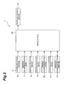
- Fig. 2 is a schematic configuration diagram of the vehicle control apparatus.
- the vehicle control apparatus 1 includes a communication device 6, a rear/front circumstances detection device 7, an obstacle detection device 8, a stop position setting device 9, a vehicle course calculation device 10, an operation detection device 11, a vehicle state detection device 12, a vehicle ECU 15 (ECU: Electronic Control Unit), and a traveling control device 18.
- a communication device 6 a rear/front circumstances detection device 7, an obstacle detection device 8, a stop position setting device 9, a vehicle course calculation device 10, an operation detection device 11, a vehicle state detection device 12, a vehicle ECU 15 (ECU: Electronic Control Unit), and a traveling control device 18.
- ECU Electronic Control Unit
- the communication device 6 communicates with the remote control 3 by using communication means such as infrared communication. Specifically, the communication device 6 acquires driving operation information for performing a remote operation of the vehicle 2, position information indicating a current position of the remote control 3, or the like, from the remote control 3. In addition, the communication device 6 transmits the information acquired from the remote control 3 to the vehicle ECU 15.
- communication means such as infrared communication. Specifically, the communication device 6 acquires driving operation information for performing a remote operation of the vehicle 2, position information indicating a current position of the remote control 3, or the like, from the remote control 3. In addition, the communication device 6 transmits the information acquired from the remote control 3 to the vehicle ECU 15.
- the rear/front circumstances detection device 7 detects rear and front circumstances of the vehicle 2, and notifies a driver or the like of the detected circumstances. Specifically, the rear/front circumstances detection device 7 images a rear side and a front side of the vehicle 2 by using imaging means (not shown) such as cameras mounted on the rear part and the front part of the vehicle 2. In addition, the rear/front circumstances detection device 7 displays the captured images on a display (not shown) mounted inside the vehicle.
- the obstacle detection device 8 detects an obstacle present around the vehicle 2, and notifies a driver or the like of the detected obstacle. Specifically, the obstacle detection device 8 detects obstacles present around the vehicle 2, such as a curb stone, a wall, and a parked vehicle by using sensing means (not shown) such as a millimeter-wave radar or a laser radar, imaging means (not shown) such as a camera, a global positioning system (GPS) (not shown), and the like. Detected information includes the size, the kind and a position of an obstacle, and the like. The size, the kind and the position of an obstacle can be obtained using a well-known technique.
- the size or the kind of an obstacle may be obtained through pattern matching of a captured image obtained by the imaging means, and a position of an obstacle may be obtained by the sensing means measuring a distance or by the GPS acquiring position information.
- the obstacle detection device 8 transmits information of the detected obstacle to the vehicle ECU 15. Further, the obstacle detection device 8 overlaps and displays a model of the detected obstacle on the rear and front captured images of the vehicle 2 which are displayed on the display.
- the stop position setting device 9 sets a stop position (a position where entering of the vehicle into the parking lot is completed) where the vehicle 2 stops in order to perform a remote operation using the remote control 3. Specifically, the stop position setting device 9 sets a stop position of the vehicle 2 on a displayed screen of the display by the driver operating a pointing device such as a touch panel or an operation button. In addition, the stop position setting device 9 transmits the set stop position to the vehicle ECU 15.
- the vehicle course calculation device 10 calculates a course along which the vehicle 2 travels through a remote operation using the remote control 3. Specifically, the vehicle course calculation device 10 calculates a course of the vehicle 2 from the current position of the vehicle 2 acquired from the GPS or the like to the stop position set by the stop position setting device 9. In this calculation of a course, the vehicle course calculation device 10 makes it a condition that the vehicle does not collide with the obstacle detected by the obstacle detection device 8. Further, the vehicle course calculation device 10 calculates a traveling plan in which forward movement, backward movement, acceleration, deceleration, constant speed traveling, steering, and the like are combined, such that the vehicle 2 travels along the calculated course. In addition, the vehicle course calculation device 10 transmits the calculated course and traveling plan of the vehicle 2 to the vehicle ECU 15.
- the operation detection device 11 detects various operations from inside of the vehicle. Specifically, the operation detection device 11 detects driving operations which are performed inside the vehicle by the driver, such as an acceleration operation (a start operation, an acceleration operation, or the like), a braking operation (a deceleration operation, a stopping operation, or the like), a steering operation, and a shift operation. In addition, the operation detection device 11 transmits information of the detected driving operation to the vehicle ECU 15. For this reason, the vehicle ECU 15 acquires the driving operation information transmitted from the operation detection device 11 and thereby can recognize whether or not there is a driving operation from inside of the vehicle by the driver, and content of the driving operation performed from inside of the vehicle by the driver.
- driving operations which are performed inside the vehicle by the driver
- driving operations which are performed inside the vehicle by the driver
- the operation detection device 11 transmits information of the detected driving operation to the vehicle ECU 15. For this reason, the vehicle ECU 15 acquires the driving operation information transmitted from the operation detection device 11 and thereby can recognize whether or not there is a driving operation
- the vehicle state detection device 12 detects various states of the vehicle 2. Specifically, the vehicle state detection device 12 includes an opening and closing sensor detecting opening and closing of doors of the vehicle 2, a seating sensor detecting whether or not a driver's seat is being taken, and the like. In addition, the vehicle state detection device 12 transmits the vehicle state information detected by the sensor to the vehicle ECU 15. In other words, when the opening and closing sensor which is one of the vehicle state detection device 12 detects a closed state or an open state of the door, the detected information is transmitted to the vehicle ECU 15. Further, when the seating sensor which is one of the vehicle state detection device 12 detects that the driver takes the driver's seat, the detected information is transmitted to the vehicle ECU 15.
- the vehicle ECU 15 is a control unit which performs traveling control of the vehicle 2 on the basis of a driving operation (direct operation) from inside of the vehicle by the driver and a driving operation (remote operation) from the remote control 3. Specifically, the vehicle ECU 15 performs traveling control of the vehicle 2 through a remote operation using the remote control 3 on the basis of the information which is acquired by the communication device 6 and is transmitted from the remote control 3, the obstacle information detected by the obstacle detection device 8, the stop position information set by the stop position setting device 9, the course and traveling plan of the vehicle 2 calculated by the vehicle course calculation device 10, the driving operation information detected by the operation detection device 11, and the vehicle state information detected by the vehicle state detection device 12. In addition, detailed content processed by the vehicle ECU 15 will be described later.
- the traveling control device 18 performs specific traveling control of the vehicle 2 on the basis of the traveling control by the vehicle ECU 15. Specifically, the traveling control device 18 includes a driving force control unit which controls the magnitude of a driving force, a braking force control unit which controls the magnitude of a braking force, a steering control unit which controls a steering angle, and the like.
- Fig. 3 is a schematic configuration diagram of the remote control which performs a remote operation of the vehicle.
- the remote control 3 includes an input device 21, a position detecting device 22, and a communication device 25.
- the input device 21 allows an operator of the remote control 3 to perform a remote operation of the vehicle 2.
- the input device 21 is constituted by a remote operation button such as a keypad displayed on a touch panel type display or a push button.
- the input device 21 is correlated with a driving operation function for driving the vehicle 2 through a remote operation.
- the input device 21 has a driving operation function of moving the vehicle 2 according to a course and a traveling plan calculated by the vehicle course calculation device 10 of the vehicle control apparatus 1, and respective driving operation functions of performing forward movement, backward movement, acceleration, deceleration, constant speed traveling, emergency stopping, and steering of the vehicle 2.
- the input device 21 transmits the operation information to the communication device 25.
- the position detecting device 22 detects a position of the remote control 3. Specifically, the position detecting device 22 detects a position of the remote control 3 by acquiring position information from GPS, by acquiring a relative position with the vehicle 2 through communication with the vehicle control apparatus 1, or the like. In addition, the position detecting device 22 transmits the acquired position information of the remote control 3 to the communication device 25. Thereby, the operator can perform a driving operation of the vehicle 2 from the remote control 3 by operating the input device 21.
- the communication device 25 communicates with the remote control 3 by using communication means such as infrared communication. Specifically, the communication device 25 transmits operation information which is operated in the input device 21 to the communication device 6 of the vehicle control apparatus 1 and also transmits position information of the remote control 3 detected by the position detecting device 22 to the communication device 6 of the vehicle control apparatus 1.
- Fig. 4 is a diagram illustrating a state in which a vehicle is made to enter a parking lot through a remote operation using the remote control.
- Fig. 5 is a diagram illustrating a display example of a display installed inside the vehicle.
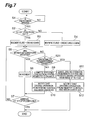
- Fig. 6 is a flowchart illustrating a process operation of the vehicle control apparatus.
- a case is considered in which the vehicle 2 is moved backward and enters a parking lot which is narrow to an extent in which doors of the vehicle cannot be opened.
- the vehicle 2 is made to enter the parking lot through a remote operation using the remote control 3.
- the vehicle 2 is stopped in front of a parking lot which the vehicle is desired to enter. Then, as shown in Fig. 5 , on the display installed inside the vehicle, models of obstacles which are present around the vehicle 2 and are detected by the obstacle detection device 8 are displayed so as to overlap a captured image of the rear side of the vehicle 2, obtained by the rear/front circumstances detection device 7.
- the reference sign A indicates a wall surrounding the parking lot
- the reference sign B indicates models of obstacles detected by the obstacle detection device 8.
- the vehicle ECU 15 determines whether or not the vehicle is remotely operated using the remote control 3 (step S1). This determination is performed based on whether or not the driver selects a remote operation using the remote control 3 through the display, the operation button, or the like installed in the vehicle 2.
- step S2 If it is determined that the vehicle is remotely operated using the remote control 3 in step S 1, the vehicle ECU 15 determines whether or not a stop position of the vehicle 2 is set (step S2).
- a stop position of the vehicle 2 In a case where the vehicle 2 is moved backward along a simple linear course, a stop position of the vehicle 2 can be obtained when a course of the vehicle 2 is calculated by the vehicle course calculation device 10. For this reason, in this case, a stop position of the vehicle 2 is not particularly and necessarily set in step S2. On the other hand, in a case where the vehicle 2 cannot be moved backward along a simple linear course, a course of the vehicle 2 cannot be calculated by the vehicle course calculation device 10 unless a stop position of the vehicle 2 is set. For this reason, in this case, a stop position of the vehicle 2 is required to be set in step S2.
- step S2 whether or not a stop position of the vehicle 2 is set is determined based on whether or not the vehicle 2 can be moved backward along a simple linear course. In addition, this determination may be performed based on an operation by the driver or may be performed based on calculation by the vehicle ECU 15.
- step S2 YES
- the vehicle ECU 15 sets a stop position of the vehicle 2 using the stop position setting device 9, and calculates a course and a traveling plan of the vehicle 2 using the vehicle course calculation device 10 (step S3).
- the setting of a stop position may be performed, for example, as shown in Fig. 5 , by displaying a captured image of the rear side of the vehicle 2 on the touch panel type display and the driver touching a stop position with the finger.
- the vehicle ECU 15 displays the course calculated in step S3 on the display, and when the driver checks the course displayed on the display, the vehicle ECU 15 decides the checked course as a course along which the vehicle 2 is moved through a remote operation using the remote control 3.
- step S2 if it is determined that a stop position of the vehicle 2 is not set in step S2 (step S2: NO), the vehicle ECU 15 omits setting of a stop position by the driver and calculates a course and a traveling plan of the vehicle 2 (step S4). In addition, a course of the vehicle 2 is set to a simple linear shape in step S4. Further, the vehicle ECU 15 displays the linear course calculated in step S4 on the display, and when the driver checks the linear course displayed on the display, the vehicle ECU 15 decides the checked linear course as a course along which the vehicle 2 is moved through a remote operation using the remote control 3.
- the vehicle ECU 15 determines whether or not movement conditions of the remote operation are satisfied (step S5).
- the movement conditions of the remote operation are conditions for determining whether or not a remote operation of the vehicle 2 using the remote control 3 is allowable, and may include, for example, the following eleven items.
- Movement condition 1 A stop position being set. Specifically, if it is determined that a stop position of the vehicle 2 is set in step S2 (step S2: YES), the movement condition is that this stop position is correctly set. In addition, if it is determined that a stop position of the vehicle 2 is not set in step S2 (step S2: NO), the movement condition 1 is excluded.
- Movement condition 2 A course along which the vehicle 2 is moved through a remote operation using the remote control 3 being checked by a driver. Specifically, the movement condition is that the course calculated in step S3 or step S4 is checked by the driver. In addition, the checking performed by the driver may be determined, for example, by displaying a keypad for checking on the touch panel type display and based on whether or not this keypad is touched.
- Movement condition 3 The remote control 3 being operated from outside of the vehicle. Specifically, the movement condition is that a position of the remote control 3 which is specified by position information transmitted from the remote control 3 is outside of the vehicle. In addition, transmission of position information from the remote control 3 to the vehicle control apparatus 1 may be performed in the event of the vehicle control apparatus 1 requesting the remote control 3 to transmit position information, or may be performed periodically by the remote control 3 regardless of a transmission request from the vehicle control apparatus 1.
- Movement condition 4 No person taking a driver's seat. Specifically, the movement condition is that the seating sensor of the vehicle state detection device 12 does not detect that a person takes a driver's seat.
- Movement condition 5 No driving operation being performed from inside of the vehicle. Specifically, the movement condition is that the operation detection device 11 detects no driving operation.
- Movement condition 6 A door of the vehicle 2 not being open. Specifically, the movement condition is that the opening and closing sensor of the vehicle state detection device 12 detects a closed state of the door.
- Movement condition 7 Electric waves of the remote control 3 arriving at the vehicle 2. Specifically, the movement condition is that communication between the communication device 25 of the remote control 3 and the communication device 6 of the vehicle control apparatus 1 is normally performed.
- Movement condition 8 No obstacle such as a person being present in a course along which the vehicle 2 is moved through a remote operation using the remote control 3. Specifically, the movement condition is that the obstacle detection device 8 detects no obstacle in the course decided in step S3 or step S4.
- Movement condition 9 Movement of the vehicle 2 being observed from an operator of the remote control 3. Specifically, the movement condition is that the obstacle detection device 8 detects no obstacle between a position of the remote control 3 specified by position information transmitted from the remote control 3 and the course decided in step S3 or step S4.
- Movement condition 10 An operator of the remote control 3 being a person who maintains a driver's license. Specifically, the movement condition is that a fingerprint registration device is mounted in the remote control 3, a fingerprint of a person maintaining a driver's license is registered, and this registered fingerprint matches a detected fmgerprint. In addition, this movement condition may be realized by mounting child lock in the remote control 3 and canceling the child lock.
- Movement condition 11 In a case where a stop position is not set, an operator of the remote control 3 standing on the front side of a movement direction of the vehicle 2. Specifically, in a case where a stop position of the vehicle 2 is not set (step S2: NO, and step S4), since the operator of the remote control 3 moves and stops the vehicle 2 through a remote operation using the remote control 3, the operator of the remote control 3 is required to reliably check a movement of the vehicle 2. Therefore, in this case, the movement condition is that a position of the remote control 3 specified by position information transmitted from the remote control 3 is the front side of a movement direction of the vehicle 2.
- step S5 YES
- the vehicle ECU 15 moves the vehicle 2 according to the course and traveling plan decided in step S3 or step S4 while the remote operation button of the remote control 3 is pushed (step S6). At this time, when the remote operation button of the remote control 3 is released, the vehicle ECU 15 decelerates and stops the vehicle 2.
- the vehicle ECU 15 determines whether or not the vehicle 2 arrives at the stop position (step S7). Specifically, it is determined that the vehicle 2 arrives at the stop position when the vehicle 2 which is moved through a remote operation using the remote control 3 arrives at the stop position set in step S3. On the other hand, it is determined that the vehicle 2 does not arrive at the stop position when the vehicle 2 which is moved through a remote operation using the remote control 3 does not arrive at the stop position set in step S3.
- step S7: NO if it is determined that the vehicle 2 does not arrive at the stop position in step S7 (step S7: NO), the vehicle ECU 15 returns to step S5 and repeatedly performs the above-described processes again. On the other hand, if it is determined that the vehicle 2 arrives at the stop position in step S7 (step S7: YES), the vehicle ECU 15 finishes the process.
- step S8 determines whether or not a driving operation from inside of the vehicle is performed (step S8). Specifically, in step S8, the determination is performed based on whether or not the movement condition 5 among the respective movement conditions in step S5 is satisfied.
- determination targets in step S8 are not necessarily all driving operations but may be some driving operations. For example, only a braking operation which is a deceleration operation or a stopping operation may be a determination target.
- step S8 if it is determined that a driving operation from inside of the vehicle is not performed in step S8 (step S8: NO), the vehicle ECU 15 cancels a driving operation from the remote control 3 (step S9). Further, since the movement condition 4 is that a person does not take a driver's seat in step S5, a driving operation from the remote control 3 is canceled in step S9, while the driver's seat is not being taken. Furthermore, a notification that a driving operation from the remote control 3 has been canceled is sent (step S10). In addition, the notification in step S10 may be performed, for example, using a sound announcement from a speaker mounted inside the vehicle, or a video announcement from the display mounted inside the vehicle.
- step S7 the vehicle ECU 15 returns to step S5 and repeatedly performs the above-described processes until the vehicle 2 arrives at the stop position (step S7), and finishes the process when the vehicle 2 arrives at the stop position.
- step S8 YES
- the vehicle ECU 15 cancels the driving operation from the remote control 3 and preferentially executes the driving operation from inside of the vehicle (step S11).
- step S11 a driving operation from inside of the vehicle and a driving operation from the remote control 3 come into conflict
- the driving operation from inside of the vehicle is prioritized.
- a notification that traveling control from the remote control 3 has been canceled is sent (step S12). Further, the notification in step S12 may be performed in the same manner as the notification in step S10.
- the vehicle ECU 15 finishes the process without performing a driving operation using the remote control 3.
- the driving operation from inside of the vehicle is prioritized, and thereby it is possible to prevent a remote operation of the vehicle 2 which is not intended by a driver.
- step S8 and step S11 the operation from inside of the vehicle is prioritized through the processes in step S8 and step S11, and thus it is possible to prevent a remote operation of the vehicle 2 which is not intended by a driver.
- a driving operation from the remote control 3 is canceled while the driver's seat is being taken, and thus it is possible to prevent a remote operation of the vehicle which is not intended by a driver.
- the second embodiment is basically the same as the first embodiment, and only some of the process operations by the vehicle ECU 15 are different. For this reason, hereinafter, only a part different from the first embodiment will be described, and description of the same part as the first embodiment will be omitted.
- Fig. 7 is a flowchart illustrating a process operation performed by the vehicle control apparatus in the second embodiment. As shown in Fig. 7 , the vehicle ECU 15 sequentially performs step S1 to step S7 in the same manner as in the first embodiment.
- step S21 the vehicle ECU 15 determines whether or not the same type of operation is performed at inside of the vehicle and the remote control 3 (step S21). Specifically, in step S21, the type of driving operation from inside of the vehicle, detected by the operation detection device 11 is compared with the type of driving operation from the remote control 3, acquired via the communication device 6, and if the types are the same, it is determined that the same type of operation is performed at inside of the vehicle and the remote control 3, and if the types are different, it is determined that the same type of operation is not performed at inside of the vehicle and the remote control 3.
- step S21 determines that the same type of operation is not performed at inside of the vehicle and the remote control 3 in step S21 (step S21: NO)
- the vehicle ECU 15 proceeds to step S9, and performs the same processes as in the first embodiment therefrom.
- step S21 YES
- the vehicle ECU 15 proceeds to step S11, and performs the same processes as in the first embodiment therefrom.
- a driving operation from inside of the vehicle is prioritized through the processes in step S21 and step S11, and thus it is possible to prevent a remote operation of the vehicle 2 which is not intended by a driver.
- the present invention is not limited to the above-described embodiments.
- the driving operations from the remote control 3 may be prioritized in a case where driving operations other than stopping and deceleration operations are performed from inside of the vehicle, and driving operations of the stopping and deceleration operations are performed from the remote control 3.
- the present invention is applicable to a vehicle control apparatus which performs traveling control of a vehicle through a remote operation.
- Vehicle Control Apparatus 1 Vehicle Control Apparatus, 2 Vehicle, 3 Remote Control (Wireless Terminal), 6 Communication Device, 7 Rear/Front Circumstances Detection Device, 8 Obstacle Detection Device, 9 Stop Position Setting Device, 10 Vehicle Course Calculation Device, 11 Operation Detection Device, 12 Vehicle State Detection Device, 15 Vehicle ECU, 18 Traveling Control Device, 21 Input Device, 22 Position Detecting Device, 25 Communication Device
Applications Claiming Priority (1)
| Application Number | Priority Date | Filing Date | Title |
|---|---|---|---|
| PCT/JP2011/051924 WO2012104964A1 (ja) | 2011-01-31 | 2011-01-31 | 車両制御装置 |
Publications (3)
| Publication Number | Publication Date |
|---|---|
| EP2672354A1 true EP2672354A1 (de) | 2013-12-11 |
| EP2672354A4 EP2672354A4 (de) | 2017-08-09 |
| EP2672354B1 EP2672354B1 (de) | 2020-03-04 |
Family
ID=46602212
Family Applications (1)
| Application Number | Title | Priority Date | Filing Date |
|---|---|---|---|
| EP11857450.8A Active EP2672354B1 (de) | 2011-01-31 | 2011-01-31 | Steuerungsvorrichtung für ein fahrzeug |
Country Status (6)
| Country | Link |
|---|---|
| US (1) | US8958929B2 (de) |
| EP (1) | EP2672354B1 (de) |
| JP (1) | JP5704178B2 (de) |
| KR (1) | KR101532855B1 (de) |
| CN (1) | CN103348296B (de) |
| WO (1) | WO2012104964A1 (de) |
Cited By (6)
| Publication number | Priority date | Publication date | Assignee | Title |
|---|---|---|---|---|
| EP3182239A4 (de) * | 2014-09-22 | 2017-09-06 | Mitsubishi Heavy Industries, Ltd. | Fahrzeugbetriebsvorrichtung und fahrzeug |
| WO2018077647A1 (de) * | 2016-10-26 | 2018-05-03 | Volkswagen Aktiengesellschaft | Verfahren sowie system zur externen steuerung eines autonomen fahrzeugs |
| WO2018137841A1 (en) * | 2017-01-30 | 2018-08-02 | Jaguar Land Rover Limited | Controlling movement of a vehicle |
| CN110832566A (zh) * | 2017-06-30 | 2020-02-21 | 株式会社电装 | 控制装置 |
| WO2020048718A1 (de) * | 2018-09-06 | 2020-03-12 | Volkswagen Aktiengesellschaft | Konzept zum überwachen und planen einer bewegung eines fortbewegungsmittels |
| EP3526092A4 (de) * | 2016-10-14 | 2020-06-17 | LG Electronics Inc. -1- | Auf einem fahrzeug montierte fahrzeugsteuerungsvorrichtung und verfahren zur steuerung des fahrzeugs |
Families Citing this family (25)
| Publication number | Priority date | Publication date | Assignee | Title |
|---|---|---|---|---|
| DE102011112371A1 (de) * | 2011-09-02 | 2013-03-07 | Audi Ag | Vorrichtung zur Einstellung wenigstens eines Betriebsparameters wenigstens eines Fahrzeugsystems eines Kraftfahrzeugs |
| WO2014162753A1 (ja) * | 2013-04-04 | 2014-10-09 | トヨタ自動車株式会社 | 駐車支援装置及び退出支援装置 |
| DE102013012394A1 (de) * | 2013-07-26 | 2015-01-29 | Daimler Ag | Verfahren und Vorrichtung zur Fernsteuerung einer Funktion eines Fahrzeugs |
| JP6314849B2 (ja) * | 2015-01-15 | 2018-04-25 | トヨタ自動車株式会社 | 車両制御装置 |
| US9340197B1 (en) * | 2015-01-23 | 2016-05-17 | Robert Bosch Gmbh | Vehicle and method of controlling |
| US11046335B2 (en) * | 2015-02-06 | 2021-06-29 | Cattron North America, Inc. | Devices, systems, and methods related to tracking location of operator control units for locomotives |
| US10023210B2 (en) * | 2015-02-06 | 2018-07-17 | Laird Technologies, Inc. | Devices, systems, and methods related to tracking location of operator control units for locomotives |
| US11926353B2 (en) | 2015-02-06 | 2024-03-12 | Cattron North America, Inc. | Devices, systems, and methods related to tracking location of operator control units for locomotives |
| DE102015204361A1 (de) | 2015-03-11 | 2016-09-15 | Robert Bosch Gmbh | Verfahren und Vorrichtung zum Erzeugen einer Zugriffsmöglichkeit auf einen Fahrzeuginnenraum |
| US9646430B2 (en) * | 2015-06-15 | 2017-05-09 | Deere & Company | Vehicle operation management system with automatic sequence detection |
| JP6237725B2 (ja) * | 2015-07-27 | 2017-11-29 | トヨタ自動車株式会社 | 乗員情報取得装置及び車両制御システム |
| WO2018037945A1 (ja) * | 2016-08-22 | 2018-03-01 | ソニーモバイルコミュニケーションズ株式会社 | 車両、および制御方法 |
| JP6870270B2 (ja) * | 2016-10-14 | 2021-05-12 | 日産自動車株式会社 | 無人運転システムの遠隔操作方法と遠隔操作装置 |
| GB2559171B (en) | 2017-01-30 | 2020-06-03 | Jaguar Land Rover Ltd | Apparatus and method for controlling movement of a vehicle |
| GB2588034B (en) * | 2017-01-30 | 2021-07-14 | Jaguar Land Rover Ltd | Controlling movement of a vehicle |
| KR102287314B1 (ko) * | 2017-03-13 | 2021-08-09 | 현대자동차주식회사 | 운전자 지원 장치 및 그 동작 방법 |
| KR102304849B1 (ko) * | 2017-03-16 | 2021-09-27 | 현대자동차주식회사 | 차량의 원격 자동 주차 시스템 및 그의 제어방법 |
| WO2019008745A1 (ja) * | 2017-07-07 | 2019-01-10 | 三菱電機株式会社 | 自動駐車支援装置および自動駐車支援方法 |
| EP3459827B1 (de) * | 2017-09-25 | 2022-07-27 | Volvo Car Corporation | Verfahren und system zum automatisierten parken eines fahrzeugs |
| JP7165616B2 (ja) * | 2019-03-29 | 2022-11-04 | 本田技研工業株式会社 | 車両制御システム |
| JP7184695B2 (ja) | 2019-03-29 | 2022-12-06 | 本田技研工業株式会社 | 車両制御システム |
| JP7123845B2 (ja) | 2019-03-29 | 2022-08-23 | 本田技研工業株式会社 | 車両制御システム |
| JP7269069B2 (ja) | 2019-03-29 | 2023-05-08 | 本田技研工業株式会社 | 車両制御システム |
| JP7075909B2 (ja) * | 2019-03-29 | 2022-05-26 | 本田技研工業株式会社 | 車両制御システム |
| JP7372599B2 (ja) * | 2020-09-15 | 2023-11-01 | トヨタ自動車株式会社 | 車両制御装置 |
Family Cites Families (54)
| Publication number | Priority date | Publication date | Assignee | Title |
|---|---|---|---|---|
| US3819932A (en) * | 1972-03-22 | 1974-06-25 | Gen Signal Corp | Multi-computer automatic vehicle control system |
| US4093161A (en) * | 1977-04-25 | 1978-06-06 | General Signal Corporation | Control system with improved communication for centralized control of vehicles |
| JPS63301172A (ja) | 1987-05-29 | 1988-12-08 | Kubota Ltd | 遠隔操縦式作業車の走行制御装置 |
| US4931930A (en) * | 1988-04-19 | 1990-06-05 | Industrial Technology Research Institute | Automatic parking device for automobile |
| US7092894B1 (en) * | 1994-09-01 | 2006-08-15 | Harris Corporation | Cost reactive scheduler and method |
| JPH1083219A (ja) * | 1996-09-09 | 1998-03-31 | Yanmar Agricult Equip Co Ltd | 自走車両の制御モード切換装置 |
| JPH1093219A (ja) | 1996-09-17 | 1998-04-10 | Toshiba Corp | 高周波集積回路およびその製造方法 |
| US7366595B1 (en) * | 1999-06-25 | 2008-04-29 | Seiko Epson Corporation | Vehicle drive assist system |
| JP3508665B2 (ja) * | 1999-12-24 | 2004-03-22 | 株式会社豊田自動織機 | 操舵支援装置 |
| EP1148461B1 (de) * | 2000-04-05 | 2004-09-22 | Matsushita Electric Industrial Co., Ltd. | System und Verfahren zur Fahrerunterstützung |
| JP2002036991A (ja) * | 2000-07-27 | 2002-02-06 | Honda Motor Co Ltd | 駐車支援装置 |
| US20040139238A1 (en) * | 2000-12-27 | 2004-07-15 | Luhrs Peter A. | Programmable switching system |
| US7131614B2 (en) * | 2003-05-22 | 2006-11-07 | General Electric Company | Locomotive control system and method |
| JP3692082B2 (ja) * | 2002-01-23 | 2005-09-07 | トヨタ自動車株式会社 | 駐車支援装置 |
| JP4342146B2 (ja) * | 2002-04-08 | 2009-10-14 | アイシン精機株式会社 | 駐車補助装置 |
| US7792089B2 (en) * | 2002-07-31 | 2010-09-07 | Cattron-Theimeg, Inc. | System and method for wireless remote control of locomotives |
| JP4234374B2 (ja) * | 2002-08-21 | 2009-03-04 | 三菱自動車工業株式会社 | 駐車支援装置 |
| DE10250021A1 (de) * | 2002-10-25 | 2004-05-13 | Donnelly Hohe Gmbh & Co. Kg | Verfahren zum Betrieb eines Darstellungssystems in einem Fahrzeug zum Auffinden eines Parkplatzes |
| DE10251558A1 (de) * | 2002-11-06 | 2004-05-19 | Bayerische Motoren Werke Ag | Verfahren zur Ermittlung von Geometriedaten für Einparkvorgänge von Fahrzeugen |
| CA2453754A1 (en) * | 2002-12-20 | 2004-06-20 | Cattron Intellectual Property Corporation | Remote control system for a locomotive |
| JP3931857B2 (ja) * | 2003-07-23 | 2007-06-20 | トヨタ自動車株式会社 | 駐車支援装置及び後退支援装置 |
| JP4052198B2 (ja) * | 2003-07-25 | 2008-02-27 | 株式会社デンソー | 車両誘導装置、および経路判定プログラム |
| JP3809431B2 (ja) * | 2003-08-28 | 2006-08-16 | トヨタ自動車株式会社 | 駐車支援装置 |
| JP3883529B2 (ja) * | 2003-08-28 | 2007-02-21 | アイシン精機株式会社 | 車両後退支援装置 |
| DE10351894A1 (de) * | 2003-11-06 | 2005-06-09 | Robert Bosch Gmbh | Verfahren zur Ermittlung einer Parklücke |
| JP2005229831A (ja) | 2004-02-17 | 2005-09-02 | Iseki & Co Ltd | 農作業機 |
| DE102004012604B4 (de) * | 2004-03-12 | 2006-10-12 | Donnelly Hohe Gmbh & Co. Kg | Verfahren zum Betrieb eines Darstellungssystems in einem Fahrzeug zum Anfahren eines Parkplatzes |
| JP4466200B2 (ja) * | 2004-04-19 | 2010-05-26 | 株式会社豊田自動織機 | 駐車支援装置 |
| JP2005313710A (ja) * | 2004-04-27 | 2005-11-10 | Toyota Motor Corp | 駐車支援装置 |
| JP4239941B2 (ja) | 2004-09-22 | 2009-03-18 | トヨタ自動車株式会社 | 遠隔操作制御装置および遠隔操作制御方法 |
| JP4507884B2 (ja) * | 2005-01-11 | 2010-07-21 | トヨタ自動車株式会社 | 遠隔制御システム及び遠隔制御装置を備える車両 |
| JP2006347334A (ja) | 2005-06-15 | 2006-12-28 | Toyota Motor Corp | 遠隔操作装置 |
| JP2007099261A (ja) * | 2005-09-12 | 2007-04-19 | Aisin Aw Co Ltd | 駐車支援方法及び駐車支援装置 |
| US20070158128A1 (en) * | 2006-01-11 | 2007-07-12 | International Business Machines Corporation | Controlling driver behavior and motor vehicle restriction control |
| US8630757B2 (en) * | 2006-03-20 | 2014-01-14 | General Electric Company | System and method for optimizing parameters of multiple rail vehicles operating over multiple intersecting railroad networks |
| JP4432929B2 (ja) * | 2006-04-25 | 2010-03-17 | トヨタ自動車株式会社 | 駐車支援装置及び駐車支援方法 |
| JP2008033438A (ja) | 2006-07-26 | 2008-02-14 | Toyota Motor Corp | 車両遠隔操作システム |
| US8229607B2 (en) * | 2006-12-01 | 2012-07-24 | General Electric Company | System and method for determining a mismatch between a model for a powered system and the actual behavior of the powered system |
| JP4268199B2 (ja) * | 2007-05-14 | 2009-05-27 | 富士通テン株式会社 | 始動制御装置および始動制御方法 |
| KR101081863B1 (ko) * | 2007-12-09 | 2011-11-14 | 봉래 박 | 협소 공간 차량 저속 이동 구현 장치 및 구현 방법 |
| KR101188588B1 (ko) * | 2008-03-27 | 2012-10-08 | 주식회사 만도 | 모노큘러 모션 스테레오 기반의 주차 공간 검출 장치 및방법 |
| DE102008024964A1 (de) * | 2008-05-23 | 2009-11-26 | Valeo Schalter Und Sensoren Gmbh | Verfahren zum Betrieb eines Fahrassistenzsystems beim Einparken eines Fahrzeugs in eine Parklücke |
| US8417415B2 (en) * | 2008-07-02 | 2013-04-09 | Michael Phelan | Driver authentication system and method for monitoring and controlling vehicle usage |
| US8340870B2 (en) * | 2008-09-16 | 2012-12-25 | Honda Motor Co., Ltd. | Vehicle maneuver assistance device |
| US20100152972A1 (en) * | 2008-12-15 | 2010-06-17 | Joe Charles Attard | Parallel park assist |
| TWI338646B (en) * | 2008-12-18 | 2011-03-11 | Univ Nat Pingtung Sci & Tech | Parking assisting system |
| JP5067377B2 (ja) | 2009-02-10 | 2012-11-07 | 株式会社デンソー | 駐車支援システム、車載駐車支援装置 |
| US20100280711A1 (en) * | 2009-04-29 | 2010-11-04 | Gm Global Technology Operations, Inc. | System and method of using a portable device to recognize a frequent driver |
| US8543257B2 (en) * | 2010-02-16 | 2013-09-24 | Toyota Jidosha Kabushiki Kaisha | Vehicle remote operation system and on-board device |
| JP5605617B2 (ja) * | 2010-05-26 | 2014-10-15 | アイシン精機株式会社 | 駐車支援装置 |
| JP2012066689A (ja) * | 2010-09-24 | 2012-04-05 | Fujitsu Ten Ltd | 車両制御システム、車両制御方法、及び、エンジン制御装置 |
| JP5472248B2 (ja) * | 2011-09-27 | 2014-04-16 | 株式会社デンソー | 隊列走行装置 |
| US20140143839A1 (en) * | 2011-11-16 | 2014-05-22 | Flextronics Ap, Llc. | On board vehicle remote control module |
| US9096234B2 (en) * | 2012-11-20 | 2015-08-04 | General Motors Llc | Method and system for in-vehicle function control |
-
2011
- 2011-01-31 JP JP2012555591A patent/JP5704178B2/ja active Active
- 2011-01-31 EP EP11857450.8A patent/EP2672354B1/de active Active
- 2011-01-31 CN CN201180066514.1A patent/CN103348296B/zh active Active
- 2011-01-31 WO PCT/JP2011/051924 patent/WO2012104964A1/ja active Application Filing
- 2011-01-31 US US13/982,529 patent/US8958929B2/en active Active
- 2011-01-31 KR KR1020137022062A patent/KR101532855B1/ko active IP Right Grant
Non-Patent Citations (1)
| Title |
|---|
| See references of WO2012104964A1 * |
Cited By (10)
| Publication number | Priority date | Publication date | Assignee | Title |
|---|---|---|---|---|
| EP3182239A4 (de) * | 2014-09-22 | 2017-09-06 | Mitsubishi Heavy Industries, Ltd. | Fahrzeugbetriebsvorrichtung und fahrzeug |
| US10942512B2 (en) | 2014-09-22 | 2021-03-09 | Mitsubishi Heavy Industries Engineering, Ltd. | Vehicle operating device, and vehicle |
| EP3526092A4 (de) * | 2016-10-14 | 2020-06-17 | LG Electronics Inc. -1- | Auf einem fahrzeug montierte fahrzeugsteuerungsvorrichtung und verfahren zur steuerung des fahrzeugs |
| WO2018077647A1 (de) * | 2016-10-26 | 2018-05-03 | Volkswagen Aktiengesellschaft | Verfahren sowie system zur externen steuerung eines autonomen fahrzeugs |
| WO2018137841A1 (en) * | 2017-01-30 | 2018-08-02 | Jaguar Land Rover Limited | Controlling movement of a vehicle |
| CN110290985A (zh) * | 2017-01-30 | 2019-09-27 | 捷豹路虎有限公司 | 控制车辆的运动 |
| US11415979B2 (en) | 2017-01-30 | 2022-08-16 | Jaguar Land Rover Limited | Controlling movement of a vehicle |
| CN110832566A (zh) * | 2017-06-30 | 2020-02-21 | 株式会社电装 | 控制装置 |
| WO2020048718A1 (de) * | 2018-09-06 | 2020-03-12 | Volkswagen Aktiengesellschaft | Konzept zum überwachen und planen einer bewegung eines fortbewegungsmittels |
| US11934188B2 (en) | 2018-09-06 | 2024-03-19 | Volkswagen Aktiengesellschaft | Monitoring and planning a movement of a transportation device |
Also Published As
| Publication number | Publication date |
|---|---|
| WO2012104964A1 (ja) | 2012-08-09 |
| KR20130131427A (ko) | 2013-12-03 |
| KR101532855B1 (ko) | 2015-06-30 |
| CN103348296A (zh) | 2013-10-09 |
| JP5704178B2 (ja) | 2015-04-22 |
| CN103348296B (zh) | 2015-11-25 |
| JPWO2012104964A1 (ja) | 2014-07-03 |
| US8958929B2 (en) | 2015-02-17 |
| EP2672354A4 (de) | 2017-08-09 |
| EP2672354B1 (de) | 2020-03-04 |
| US20130311004A1 (en) | 2013-11-21 |
Similar Documents
| Publication | Publication Date | Title |
|---|---|---|
| US8958929B2 (en) | Vehicle control apparatus | |
| EP2746139B1 (de) | Vorrichtung für den Fernbetrieb von Fahrzeugen | |
| US11891052B2 (en) | Parking control method and parking control device | |
| US10768616B2 (en) | Parking control method and parking control device | |
| EP2560150A1 (de) | Fahrzeugfernsteuerungssystem und bordinterne vorrichtung dafür | |
| KR101992089B1 (ko) | 장해물 판정 방법, 주차 지원 방법, 출고 지원 방법 및 장해물 판정 장치 | |
| EP3693230B1 (de) | Parksteuerungsverfahren und parksteuerungsvorrichtung | |
| WO2019030923A1 (ja) | 駐車制御方法及び駐車制御装置 | |
| JP6503285B2 (ja) | 運転制御装置、運転制御方法及びプログラム | |
| WO2018163459A1 (ja) | 搭乗者支援装置、方法及びプログラム | |
| US10847033B2 (en) | Method and obstacle assistance device for automatically activating an obstacle detection device of a motor vehicle | |
| CN111746508B (zh) | 车辆控制系统 | |
| US11348346B2 (en) | Control apparatus | |
| US10633026B2 (en) | Vehicle system and vehicle controller for controlling vehicle | |
| JP2021162959A (ja) | 収容領域管理装置 | |
| JP2018172061A (ja) | 車両制御システム、及び車両制御システムの制御方法 | |
| CN113195853B (zh) | 车辆控制方法、车辆控制装置以及车辆控制系统 | |
| CN111976594B (zh) | 用于控制无人车的方法和装置 | |
| US20220219687A1 (en) | Method for Detecting a Potential Collision by a Vehicle with a Living Thing, and Car Park Management System | |
| CN115484571A (zh) | 一种用于控制用户发起的车辆操作指令的方法和系统 | |
| CN114842630A (zh) | 信息通知系统和信息通知方法 | |
| CN114792280A (zh) | 信息通知系统以及信息通知方法 | |
| JP2016062163A (ja) | 車両停止システム |
Legal Events
| Date | Code | Title | Description |
|---|---|---|---|
| PUAI | Public reference made under article 153(3) epc to a published international application that has entered the european phase |
Free format text: ORIGINAL CODE: 0009012 |
|
| 17P | Request for examination filed |
Effective date: 20130807 |
|
| AK | Designated contracting states |
Kind code of ref document: A1 Designated state(s): AL AT BE BG CH CY CZ DE DK EE ES FI FR GB GR HR HU IE IS IT LI LT LU LV MC MK MT NL NO PL PT RO RS SE SI SK SM TR |
|
| DAX | Request for extension of the european patent (deleted) | ||
| RA4 | Supplementary search report drawn up and despatched (corrected) |
Effective date: 20170710 |
|
| RIC1 | Information provided on ipc code assigned before grant |
Ipc: B62D 15/02 20060101ALI20170704BHEP Ipc: B60W 30/06 20060101ALI20170704BHEP Ipc: G05D 1/00 20060101AFI20170704BHEP Ipc: H04Q 9/00 20060101ALI20170704BHEP Ipc: B60R 21/00 20060101ALI20170704BHEP |
|
| REG | Reference to a national code |
Ref country code: DE Ref legal event code: R079 Ref document number: 602011065437 Country of ref document: DE Free format text: PREVIOUS MAIN CLASS: G05D0001000000 Ipc: G08C0017020000 |
|
| RIC1 | Information provided on ipc code assigned before grant |
Ipc: B62D 15/02 20060101ALI20191015BHEP Ipc: B60W 30/18 20120101ALI20191015BHEP Ipc: G08C 17/02 20060101AFI20191015BHEP Ipc: G05D 1/00 20060101ALI20191015BHEP Ipc: B60W 30/06 20060101ALI20191015BHEP Ipc: G08C 23/04 20060101ALI20191015BHEP |
|
| GRAP | Despatch of communication of intention to grant a patent |
Free format text: ORIGINAL CODE: EPIDOSNIGR1 |
|
| STAA | Information on the status of an ep patent application or granted ep patent |
Free format text: STATUS: GRANT OF PATENT IS INTENDED |
|
| INTG | Intention to grant announced |
Effective date: 20191205 |
|
| GRAS | Grant fee paid |
Free format text: ORIGINAL CODE: EPIDOSNIGR3 |
|
| GRAA | (expected) grant |
Free format text: ORIGINAL CODE: 0009210 |
|
| STAA | Information on the status of an ep patent application or granted ep patent |
Free format text: STATUS: THE PATENT HAS BEEN GRANTED |
|
| AK | Designated contracting states |
Kind code of ref document: B1 Designated state(s): AL AT BE BG CH CY CZ DE DK EE ES FI FR GB GR HR HU IE IS IT LI LT LU LV MC MK MT NL NO PL PT RO RS SE SI SK SM TR |
|
| REG | Reference to a national code |
Ref country code: GB Ref legal event code: FG4D |
|
| REG | Reference to a national code |
Ref country code: CH Ref legal event code: EP |
|
| REG | Reference to a national code |
Ref country code: AT Ref legal event code: REF Ref document number: 1241269 Country of ref document: AT Kind code of ref document: T Effective date: 20200315 |
|
| REG | Reference to a national code |
Ref country code: DE Ref legal event code: R096 Ref document number: 602011065437 Country of ref document: DE |
|
| REG | Reference to a national code |
Ref country code: IE Ref legal event code: FG4D |
|
| PG25 | Lapsed in a contracting state [announced via postgrant information from national office to epo] |
Ref country code: RS Free format text: LAPSE BECAUSE OF FAILURE TO SUBMIT A TRANSLATION OF THE DESCRIPTION OR TO PAY THE FEE WITHIN THE PRESCRIBED TIME-LIMIT Effective date: 20200304 Ref country code: NO Free format text: LAPSE BECAUSE OF FAILURE TO SUBMIT A TRANSLATION OF THE DESCRIPTION OR TO PAY THE FEE WITHIN THE PRESCRIBED TIME-LIMIT Effective date: 20200604 Ref country code: FI Free format text: LAPSE BECAUSE OF FAILURE TO SUBMIT A TRANSLATION OF THE DESCRIPTION OR TO PAY THE FEE WITHIN THE PRESCRIBED TIME-LIMIT Effective date: 20200304 |
|
| REG | Reference to a national code |
Ref country code: NL Ref legal event code: MP Effective date: 20200304 |
|
| PG25 | Lapsed in a contracting state [announced via postgrant information from national office to epo] |
Ref country code: SE Free format text: LAPSE BECAUSE OF FAILURE TO SUBMIT A TRANSLATION OF THE DESCRIPTION OR TO PAY THE FEE WITHIN THE PRESCRIBED TIME-LIMIT Effective date: 20200304 Ref country code: LV Free format text: LAPSE BECAUSE OF FAILURE TO SUBMIT A TRANSLATION OF THE DESCRIPTION OR TO PAY THE FEE WITHIN THE PRESCRIBED TIME-LIMIT Effective date: 20200304 Ref country code: HR Free format text: LAPSE BECAUSE OF FAILURE TO SUBMIT A TRANSLATION OF THE DESCRIPTION OR TO PAY THE FEE WITHIN THE PRESCRIBED TIME-LIMIT Effective date: 20200304 Ref country code: BG Free format text: LAPSE BECAUSE OF FAILURE TO SUBMIT A TRANSLATION OF THE DESCRIPTION OR TO PAY THE FEE WITHIN THE PRESCRIBED TIME-LIMIT Effective date: 20200604 Ref country code: GR Free format text: LAPSE BECAUSE OF FAILURE TO SUBMIT A TRANSLATION OF THE DESCRIPTION OR TO PAY THE FEE WITHIN THE PRESCRIBED TIME-LIMIT Effective date: 20200605 |
|
| REG | Reference to a national code |
Ref country code: LT Ref legal event code: MG4D |
|
| PG25 | Lapsed in a contracting state [announced via postgrant information from national office to epo] |
Ref country code: NL Free format text: LAPSE BECAUSE OF FAILURE TO SUBMIT A TRANSLATION OF THE DESCRIPTION OR TO PAY THE FEE WITHIN THE PRESCRIBED TIME-LIMIT Effective date: 20200304 |
|
| PG25 | Lapsed in a contracting state [announced via postgrant information from national office to epo] |
Ref country code: IS Free format text: LAPSE BECAUSE OF FAILURE TO SUBMIT A TRANSLATION OF THE DESCRIPTION OR TO PAY THE FEE WITHIN THE PRESCRIBED TIME-LIMIT Effective date: 20200704 Ref country code: SM Free format text: LAPSE BECAUSE OF FAILURE TO SUBMIT A TRANSLATION OF THE DESCRIPTION OR TO PAY THE FEE WITHIN THE PRESCRIBED TIME-LIMIT Effective date: 20200304 Ref country code: EE Free format text: LAPSE BECAUSE OF FAILURE TO SUBMIT A TRANSLATION OF THE DESCRIPTION OR TO PAY THE FEE WITHIN THE PRESCRIBED TIME-LIMIT Effective date: 20200304 Ref country code: SK Free format text: LAPSE BECAUSE OF FAILURE TO SUBMIT A TRANSLATION OF THE DESCRIPTION OR TO PAY THE FEE WITHIN THE PRESCRIBED TIME-LIMIT Effective date: 20200304 Ref country code: LT Free format text: LAPSE BECAUSE OF FAILURE TO SUBMIT A TRANSLATION OF THE DESCRIPTION OR TO PAY THE FEE WITHIN THE PRESCRIBED TIME-LIMIT Effective date: 20200304 Ref country code: RO Free format text: LAPSE BECAUSE OF FAILURE TO SUBMIT A TRANSLATION OF THE DESCRIPTION OR TO PAY THE FEE WITHIN THE PRESCRIBED TIME-LIMIT Effective date: 20200304 Ref country code: CZ Free format text: LAPSE BECAUSE OF FAILURE TO SUBMIT A TRANSLATION OF THE DESCRIPTION OR TO PAY THE FEE WITHIN THE PRESCRIBED TIME-LIMIT Effective date: 20200304 Ref country code: ES Free format text: LAPSE BECAUSE OF FAILURE TO SUBMIT A TRANSLATION OF THE DESCRIPTION OR TO PAY THE FEE WITHIN THE PRESCRIBED TIME-LIMIT Effective date: 20200304 Ref country code: PT Free format text: LAPSE BECAUSE OF FAILURE TO SUBMIT A TRANSLATION OF THE DESCRIPTION OR TO PAY THE FEE WITHIN THE PRESCRIBED TIME-LIMIT Effective date: 20200729 |
|
| REG | Reference to a national code |
Ref country code: AT Ref legal event code: MK05 Ref document number: 1241269 Country of ref document: AT Kind code of ref document: T Effective date: 20200304 |
|
| REG | Reference to a national code |
Ref country code: DE Ref legal event code: R097 Ref document number: 602011065437 Country of ref document: DE |
|
| PLBE | No opposition filed within time limit |
Free format text: ORIGINAL CODE: 0009261 |
|
| STAA | Information on the status of an ep patent application or granted ep patent |
Free format text: STATUS: NO OPPOSITION FILED WITHIN TIME LIMIT |
|
| PG25 | Lapsed in a contracting state [announced via postgrant information from national office to epo] |
Ref country code: AT Free format text: LAPSE BECAUSE OF FAILURE TO SUBMIT A TRANSLATION OF THE DESCRIPTION OR TO PAY THE FEE WITHIN THE PRESCRIBED TIME-LIMIT Effective date: 20200304 Ref country code: IT Free format text: LAPSE BECAUSE OF FAILURE TO SUBMIT A TRANSLATION OF THE DESCRIPTION OR TO PAY THE FEE WITHIN THE PRESCRIBED TIME-LIMIT Effective date: 20200304 Ref country code: DK Free format text: LAPSE BECAUSE OF FAILURE TO SUBMIT A TRANSLATION OF THE DESCRIPTION OR TO PAY THE FEE WITHIN THE PRESCRIBED TIME-LIMIT Effective date: 20200304 |
|
| 26N | No opposition filed |
Effective date: 20201207 |
|
| PG25 | Lapsed in a contracting state [announced via postgrant information from national office to epo] |
Ref country code: PL Free format text: LAPSE BECAUSE OF FAILURE TO SUBMIT A TRANSLATION OF THE DESCRIPTION OR TO PAY THE FEE WITHIN THE PRESCRIBED TIME-LIMIT Effective date: 20200304 Ref country code: SI Free format text: LAPSE BECAUSE OF FAILURE TO SUBMIT A TRANSLATION OF THE DESCRIPTION OR TO PAY THE FEE WITHIN THE PRESCRIBED TIME-LIMIT Effective date: 20200304 |
|
| PG25 | Lapsed in a contracting state [announced via postgrant information from national office to epo] |
Ref country code: MC Free format text: LAPSE BECAUSE OF FAILURE TO SUBMIT A TRANSLATION OF THE DESCRIPTION OR TO PAY THE FEE WITHIN THE PRESCRIBED TIME-LIMIT Effective date: 20200304 |
|
| REG | Reference to a national code |
Ref country code: CH Ref legal event code: PL |
|
| PG25 | Lapsed in a contracting state [announced via postgrant information from national office to epo] |
Ref country code: LU Free format text: LAPSE BECAUSE OF NON-PAYMENT OF DUE FEES Effective date: 20210131 |
|
| REG | Reference to a national code |
Ref country code: BE Ref legal event code: MM Effective date: 20210131 |
|
| REG | Reference to a national code |
Ref country code: DE Ref legal event code: R084 Ref document number: 602011065437 Country of ref document: DE |
|
| PG25 | Lapsed in a contracting state [announced via postgrant information from national office to epo] |
Ref country code: LI Free format text: LAPSE BECAUSE OF NON-PAYMENT OF DUE FEES Effective date: 20210131 Ref country code: CH Free format text: LAPSE BECAUSE OF NON-PAYMENT OF DUE FEES Effective date: 20210131 |
|
| PG25 | Lapsed in a contracting state [announced via postgrant information from national office to epo] |
Ref country code: IE Free format text: LAPSE BECAUSE OF NON-PAYMENT OF DUE FEES Effective date: 20210131 |
|
| REG | Reference to a national code |
Ref country code: GB Ref legal event code: 746 Effective date: 20210107 |
|
| PG25 | Lapsed in a contracting state [announced via postgrant information from national office to epo] |
Ref country code: BE Free format text: LAPSE BECAUSE OF NON-PAYMENT OF DUE FEES Effective date: 20210131 |
|
| PG25 | Lapsed in a contracting state [announced via postgrant information from national office to epo] |
Ref country code: HU Free format text: LAPSE BECAUSE OF FAILURE TO SUBMIT A TRANSLATION OF THE DESCRIPTION OR TO PAY THE FEE WITHIN THE PRESCRIBED TIME-LIMIT; INVALID AB INITIO Effective date: 20110131 Ref country code: CY Free format text: LAPSE BECAUSE OF FAILURE TO SUBMIT A TRANSLATION OF THE DESCRIPTION OR TO PAY THE FEE WITHIN THE PRESCRIBED TIME-LIMIT Effective date: 20200304 |
|
| PGFP | Annual fee paid to national office [announced via postgrant information from national office to epo] |
Ref country code: DE Payment date: 20221207 Year of fee payment: 13 |
|
| P01 | Opt-out of the competence of the unified patent court (upc) registered |
Effective date: 20230427 |
|
| PGFP | Annual fee paid to national office [announced via postgrant information from national office to epo] |
Ref country code: GB Payment date: 20231207 Year of fee payment: 14 |
|
| PGFP | Annual fee paid to national office [announced via postgrant information from national office to epo] |
Ref country code: FR Payment date: 20231212 Year of fee payment: 14 |