WO2012104964A1 - 車両制御装置 - Google Patents
車両制御装置 Download PDFInfo
- Publication number
- WO2012104964A1 WO2012104964A1 PCT/JP2011/051924 JP2011051924W WO2012104964A1 WO 2012104964 A1 WO2012104964 A1 WO 2012104964A1 JP 2011051924 W JP2011051924 W JP 2011051924W WO 2012104964 A1 WO2012104964 A1 WO 2012104964A1
- Authority
- WO
- WIPO (PCT)
- Prior art keywords
- vehicle
- remote
- remote controller
- driver
- stop position
- Prior art date
Links
- 238000001514 detection method Methods 0.000 description 41
- 238000004891 communication Methods 0.000 description 23
- 238000010586 diagram Methods 0.000 description 8
- 238000000034 method Methods 0.000 description 5
- 230000001133 acceleration Effects 0.000 description 3
- 230000005540 biological transmission Effects 0.000 description 3
- 238000003384 imaging method Methods 0.000 description 3
- 238000012790 confirmation Methods 0.000 description 2
- 230000001143 conditioned effect Effects 0.000 description 1
- 230000001960 triggered effect Effects 0.000 description 1
Images


Classifications
-
- G—PHYSICS
- G05—CONTROLLING; REGULATING
- G05D—SYSTEMS FOR CONTROLLING OR REGULATING NON-ELECTRIC VARIABLES
- G05D1/00—Control of position, course or altitude of land, water, air, or space vehicles, e.g. automatic pilot
- G05D1/0011—Control of position, course or altitude of land, water, air, or space vehicles, e.g. automatic pilot associated with a remote control arrangement
- G05D1/0033—Control of position, course or altitude of land, water, air, or space vehicles, e.g. automatic pilot associated with a remote control arrangement by having the operator tracking the vehicle either by direct line of sight or via one or more cameras located remotely from the vehicle
-
- B—PERFORMING OPERATIONS; TRANSPORTING
- B60—VEHICLES IN GENERAL
- B60T—VEHICLE BRAKE CONTROL SYSTEMS OR PARTS THEREOF; BRAKE CONTROL SYSTEMS OR PARTS THEREOF, IN GENERAL; ARRANGEMENT OF BRAKING ELEMENTS ON VEHICLES IN GENERAL; PORTABLE DEVICES FOR PREVENTING UNWANTED MOVEMENT OF VEHICLES; VEHICLE MODIFICATIONS TO FACILITATE COOLING OF BRAKES
- B60T7/00—Brake-action initiating means
- B60T7/12—Brake-action initiating means for automatic initiation; for initiation not subject to will of driver or passenger
-
- B60K35/80—
-
- B—PERFORMING OPERATIONS; TRANSPORTING
- B60—VEHICLES IN GENERAL
- B60W—CONJOINT CONTROL OF VEHICLE SUB-UNITS OF DIFFERENT TYPE OR DIFFERENT FUNCTION; CONTROL SYSTEMS SPECIALLY ADAPTED FOR HYBRID VEHICLES; ROAD VEHICLE DRIVE CONTROL SYSTEMS FOR PURPOSES NOT RELATED TO THE CONTROL OF A PARTICULAR SUB-UNIT
- B60W30/00—Purposes of road vehicle drive control systems not related to the control of a particular sub-unit, e.g. of systems using conjoint control of vehicle sub-units, or advanced driver assistance systems for ensuring comfort, stability and safety or drive control systems for propelling or retarding the vehicle
- B60W30/06—Automatic manoeuvring for parking
-
- B—PERFORMING OPERATIONS; TRANSPORTING
- B60—VEHICLES IN GENERAL
- B60W—CONJOINT CONTROL OF VEHICLE SUB-UNITS OF DIFFERENT TYPE OR DIFFERENT FUNCTION; CONTROL SYSTEMS SPECIALLY ADAPTED FOR HYBRID VEHICLES; ROAD VEHICLE DRIVE CONTROL SYSTEMS FOR PURPOSES NOT RELATED TO THE CONTROL OF A PARTICULAR SUB-UNIT
- B60W30/00—Purposes of road vehicle drive control systems not related to the control of a particular sub-unit, e.g. of systems using conjoint control of vehicle sub-units, or advanced driver assistance systems for ensuring comfort, stability and safety or drive control systems for propelling or retarding the vehicle
- B60W30/18—Propelling the vehicle
-
- B—PERFORMING OPERATIONS; TRANSPORTING
- B62—LAND VEHICLES FOR TRAVELLING OTHERWISE THAN ON RAILS
- B62D—MOTOR VEHICLES; TRAILERS
- B62D15/00—Steering not otherwise provided for
- B62D15/02—Steering position indicators ; Steering position determination; Steering aids
- B62D15/027—Parking aids, e.g. instruction means
- B62D15/0285—Parking performed automatically
-
- G—PHYSICS
- G05—CONTROLLING; REGULATING
- G05D—SYSTEMS FOR CONTROLLING OR REGULATING NON-ELECTRIC VARIABLES
- G05D1/00—Control of position, course or altitude of land, water, air, or space vehicles, e.g. automatic pilot
- G05D1/0011—Control of position, course or altitude of land, water, air, or space vehicles, e.g. automatic pilot associated with a remote control arrangement
- G05D1/0022—Control of position, course or altitude of land, water, air, or space vehicles, e.g. automatic pilot associated with a remote control arrangement characterised by the communication link
-
- G—PHYSICS
- G05—CONTROLLING; REGULATING
- G05D—SYSTEMS FOR CONTROLLING OR REGULATING NON-ELECTRIC VARIABLES
- G05D1/00—Control of position, course or altitude of land, water, air, or space vehicles, e.g. automatic pilot
- G05D1/0011—Control of position, course or altitude of land, water, air, or space vehicles, e.g. automatic pilot associated with a remote control arrangement
- G05D1/0044—Control of position, course or altitude of land, water, air, or space vehicles, e.g. automatic pilot associated with a remote control arrangement by providing the operator with a computer generated representation of the environment of the vehicle, e.g. virtual reality, maps
-
- G—PHYSICS
- G08—SIGNALLING
- G08C—TRANSMISSION SYSTEMS FOR MEASURED VALUES, CONTROL OR SIMILAR SIGNALS
- G08C17/00—Arrangements for transmitting signals characterised by the use of a wireless electrical link
- G08C17/02—Arrangements for transmitting signals characterised by the use of a wireless electrical link using a radio link
-
- G—PHYSICS
- G08—SIGNALLING
- G08C—TRANSMISSION SYSTEMS FOR MEASURED VALUES, CONTROL OR SIMILAR SIGNALS
- G08C23/00—Non-electrical signal transmission systems, e.g. optical systems
- G08C23/04—Non-electrical signal transmission systems, e.g. optical systems using light waves, e.g. infrared
-
- B60K2360/55—
Definitions
- the present invention relates to a vehicle control device that remotely controls a vehicle using a wireless terminal.
- Patent Document 1 discloses a vehicle control device that allows a vehicle to enter and exit a narrow parking lot by remote operation of the vehicle using a remote controller.
- This vehicle control device can remotely control the steering, driving, braking, etc. of the vehicle with a remote controller, and the driver can enter the parking lot or enter the parking lot by operating the remote controller. It is possible to leave a running vehicle.
- an object of the present invention is to provide a vehicle control device that can prevent remote operation of a vehicle unintended by a driver.
- a vehicle control device is a vehicle control device that controls a vehicle by direct operation of the vehicle performed from inside the vehicle and remote operation of the vehicle performed from a wireless terminal, and at least a part of the direct operation from within the vehicle and the wireless terminal If at least part of the remote operation from the vehicle competes, direct operation from the vehicle is prioritized.
- remote operation from the wireless terminal can also be performed by a person other than the driver.
- direct operation from within the vehicle By prioritizing direct operation from within the vehicle, remote operation of the vehicle unintended by the driver can be prevented.
- the stopping and deceleration operation from the inside of the vehicle competes with the driving operation from the wireless terminal, it is preferable to give priority to the stopping and deceleration operation from the inside of the vehicle.
- priority can be given to the stopping and deceleration operation from the inside of the vehicle, thereby preventing remote operation of the vehicle not intended by the driver.
- the vehicle control device is a vehicle control device that controls a vehicle by direct operation of the vehicle from the inside of the vehicle and remote operation of the vehicle from the wireless terminal, and the wireless terminal while the driver's seat is in the seated state Cancel at least part of the remote control from.
- Drawing 1 is a mimetic diagram showing the vehicle control device concerning an embodiment. As shown in FIG. 1, a vehicle control device 1 according to this embodiment is mounted on a vehicle 2 and performs various controls of the vehicle 2, and can be remotely operated from the outside by a remote controller 3.
- FIG. 2 is a schematic configuration diagram of the vehicle control device.
- the vehicle control device 1 includes a communication device 6, a rear / front situation detection device 7, an obstacle detection device 8, a stop position setting device 9, a vehicle trajectory calculation device 10, and an operation detection.
- a device 11, a vehicle state detection device 12, a vehicle ECU 15 (ECU: Electronic Control Unit), and a travel control device 18 are provided.
- the communication device 6 communicates with the remote controller 3 using communication means such as infrared communication. More specifically, the communication device 6 acquires driving operation information for remotely operating the vehicle 2, position information indicating the current position of the remote controller 3, and the like from the remote controller 3. Then, the communication device 6 transmits information acquired from the remote controller 3 to the vehicle ECU 15.
- communication means such as infrared communication. More specifically, the communication device 6 acquires driving operation information for remotely operating the vehicle 2, position information indicating the current position of the remote controller 3, and the like from the remote controller 3. Then, the communication device 6 transmits information acquired from the remote controller 3 to the vehicle ECU 15.
- the rear / front situation detector 7 detects the situation behind and forward of the vehicle 2 and notifies the driver of the detected situation. More specifically, the rear / front situation detection device 7 images the rear and front of the vehicle 2 by imaging means (not shown) such as a camera mounted on the rear and front of the vehicle 2. The rear / front situation detection device 7 displays the captured image on a display (not shown) mounted in the vehicle.
- the obstacle detection device 8 detects an obstacle existing around the vehicle 2 and notifies the detected obstacle to a driver or the like.
- the obstacle detection device 8 includes sensing means (not shown) such as millimeter wave radar and laser radar, imaging means (not shown) such as a camera, GPS (Global Positioning System) (not shown), and the like. Used to detect obstacles such as curbs, walls, and parked vehicles existing around the vehicle 2.
- the information to be detected includes the size, type, and position of the obstacle.
- the size, type, position, and the like of the obstacle can be obtained using a known technique.
- the size and type of the obstacle can be obtained by pattern matching of the captured image taken by the imaging means, and the position of the obstacle can be obtained by ranging by the sensing means or acquisition of position information by GPS. .
- the obstacle detection device 8 transmits information on the detected obstacle to the vehicle ECU 15.
- the obstacle detection device 8 superimposes and displays the detected obstacle model on the captured images of the rear and front of the vehicle 2 displayed on the display.
- the stop position setting device 9 is for setting a stop position (parking warehousing completion position) at which the vehicle 2 is stopped in order to perform a remote operation with the remote controller 3. More specifically, the stop position setting device 9 sets the stop position of the vehicle 2 on the display screen when the driver operates a pointing device such as a touch panel or operation buttons. Then, the stop position setting device 9 transmits the set stop position to the vehicle ECU 15.
- the vehicle trajectory calculation device 10 calculates a trajectory for causing the vehicle 2 to travel by remote control with the remote controller 3. More specifically, the vehicle trajectory calculation device 10 calculates the trajectory of the vehicle 2 from the current position of the vehicle 2 acquired from GPS or the like to the stop position set by the stop position setting device 9. In calculating the trajectory, the vehicle trajectory calculation device 10 is conditioned on not colliding with the obstacle detected by the obstacle detection device 8. The vehicle trajectory calculation device 10 calculates a travel plan that combines forward, reverse, acceleration, deceleration, constant speed travel, steering, and the like so that the vehicle 2 travels on the calculated trajectory. The vehicle trajectory calculation apparatus 10 transmits the calculated trajectory and travel plan of the vehicle 2 to the vehicle ECU 15.
- the operation detection device 11 detects various operations from inside the vehicle. Specifically, the operation detection device 11 detects driving operations performed by the driver in the vehicle, such as an accelerator operation (start operation, acceleration operation, etc.), a brake operation (deceleration operation, stop operation, etc.), a steering operation, and a shift operation. To do. And the operation detection apparatus 11 transmits the information of this detected driving operation to vehicle ECU15. For this reason, the vehicle ECU 15 acquires the driving operation information transmitted from the operation detecting device 11, thereby recognizing the presence or absence of the driving operation from the vehicle by the driver and the content of the driving operation performed by the driver from the vehicle. Can do.
- driving operations performed by the driver in the vehicle such as an accelerator operation (start operation, acceleration operation, etc.), a brake operation (deceleration operation, stop operation, etc.), a steering operation, and a shift operation. To do. And the operation detection apparatus 11 transmits the information of this detected driving operation to vehicle ECU15. For this reason, the vehicle ECU 15 acquires the driving operation information transmitted
- the vehicle state detection device 12 detects various states of the vehicle 2. More specifically, the vehicle state detection device 12 includes an opening / closing sensor that detects opening / closing of the door of the vehicle 2, a seating sensor that detects whether a driver's seat is seated, or the like. Then, the vehicle state detection device 12 transmits the vehicle state information detected by these sensors to the vehicle ECU 15. That is, when the opening / closing sensor, which is one of the vehicle state detection devices 12, detects the closed state or the open state of the door, the detected information is transmitted to the vehicle ECU 15. In addition, when a seating sensor that is one of the vehicle state detection devices 12 detects that the driver is seated in the driver's seat, the seating sensor transmits the detected information to the vehicle ECU 15.
- the vehicle ECU 15 is a control unit that performs traveling control of the vehicle 2 based on the driving operation (direct operation) from the inside of the vehicle by the driver and the driving operation (remote operation) from the remote controller 3. Specifically, the vehicle ECU 15 transmits information from the remote control 3 acquired by the communication device 6, information on the obstacle detected by the obstacle detection device 8, information on the stop position set by the stop position setting device 9, vehicle Based on the track and travel plan of the vehicle 2 calculated by the track calculation device 10, the driving operation information detected by the operation detection device 11, the vehicle state information detected by the vehicle state detection device 12, etc. Travel control of the vehicle 2 is performed. The detailed processing contents of the vehicle ECU 15 will be described later.
- the traveling control device 18 performs specific traveling control of the vehicle 2 based on the traveling control by the vehicle ECU 15. Specifically, the travel control device 18 includes a driving force control unit that controls the magnitude of the driving force, a braking force control unit that controls the magnitude of the braking force, a steering control unit that controls the steering angle, and the like.
- FIG. 3 is a schematic configuration diagram of a remote controller that remotely controls the vehicle. As shown in FIG. 3, the remote controller 3 includes an input device 21, a position detection device 22, and a communication device 25.
- the input device 21 is used by the operator of the remote controller 3 to remotely operate the vehicle 2. More specifically, the input device 21 includes remote operation buttons such as a keypad and push buttons displayed on a touch panel display.
- the input device 21 is associated with a driving operation function for driving the vehicle 2 by remote control. That is, the input device 21 includes a driving operation function for moving the vehicle 2 in accordance with the track and travel plan calculated by the vehicle track calculation device 10 of the vehicle control device 1, and the vehicle 2 moving forward, backward, acceleration, deceleration, constant speed. Each driving operation function for running, emergency stop, and steering is provided.
- the input device 21 transmits the operation information to the communication device 25 when the remote operation button is operated by the operator.
- the position detection device 22 detects the position of the remote controller 3. More specifically, the position detection device 22 detects the position of the remote controller 3 by acquiring position information from the GPS or by acquiring a relative position to the vehicle 2 through communication with the vehicle control device 1. . Then, the position detection device 22 transmits the acquired position information of the remote control 3 to the communication device 25. Thus, the operator can drive the vehicle 2 from the remote controller 3 by operating the input device 21.
- the communication device 25 communicates with the remote controller 3 using communication means such as infrared communication. More specifically, the communication device 25 transmits the operation information operated by the input device 21 to the communication device 6 of the vehicle control device 1, and the position information of the remote controller 3 detected by the position detection device 22 is transmitted to the vehicle control device. 1 to the communication device 6.
- communication means such as infrared communication. More specifically, the communication device 25 transmits the operation information operated by the input device 21 to the communication device 6 of the vehicle control device 1, and the position information of the remote controller 3 detected by the position detection device 22 is transmitted to the vehicle control device. 1 to the communication device 6.
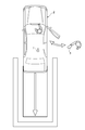
- FIG. 4 is a diagram illustrating a state in which the vehicle is stored in the parking lot by a remote operation with the remote controller.
- FIG. 5 is a diagram showing a display example of a display installed in the vehicle.
- FIG. 6 is a flowchart showing the processing operation of the vehicle control device.
- the vehicle 2 is moved backward into a narrow parking lot where the door cannot be opened as shown in FIG.
- the driver cannot leave the vehicle 2. Therefore, as will be described in detail below, the vehicle 2 is stored in the parking lot by remote control using the remote controller 3.
- the vehicle ECU 15 determines whether or not to remotely operate the vehicle with the remote controller 3 (step S1). This determination is made based on whether or not the driver has selected a remote operation by the remote controller 3 using a display or operation buttons installed in the vehicle 2.
- step S2 If it is determined in step S1 that the vehicle is remotely controlled by the remote controller 3, the vehicle ECU 15 determines whether or not to set the stop position of the vehicle 2 (step S2).
- the determination as to whether or not to set the stop position of the vehicle 2 will be described in detail.
- the stop position of the vehicle 2 can be obtained by calculating the track of the vehicle 2 by the vehicle track calculation device 10. For this reason, in this case, it is not necessary to set the stop position of the vehicle 2 in step S2.
- the vehicle track calculation device 10 cannot calculate the track of the vehicle 2 unless the stop position of the vehicle 2 is set. For this reason, in this case, it is necessary to set the stop position of the vehicle 2 in step S2.
- step S2 it is determined whether or not the stop position of the vehicle 2 is set based on whether or not the vehicle 2 can be moved backward on a simple straight track. This determination may be made based on the operation of the driver, or may be made by calculation by the vehicle ECU 15.
- step S2 If it is determined in step S2 that the stop position of the vehicle 2 is set (step S2: YES), the vehicle ECU 15 sets the stop position of the vehicle 2 by the stop position setting device 9, and the vehicle trajectory calculation device 10 sets the stop position of the vehicle 2.
- a track and a travel plan are calculated (step S3).
- the stop position can be set by displaying a captured image behind the vehicle 2 on a touch panel display, and the driver touching the stop position with a finger. Then, the vehicle ECU 15 displays the trajectory calculated in step S3 on the display, and when the driver confirms the trajectory displayed on the display, the vehicle ECU 15 moves the vehicle 2 on the confirmed trajectory by remote control using the remote controller 3. Determine as orbit.
- step S2 determines whether the stop position of the vehicle 2 is not set (step S2: NO)
- the vehicle ECU 15 omits the setting of the stop position by the driver and calculates the track and the travel plan of the vehicle 2 (step S2). S4).
- step S4 the trajectory of the vehicle 2 is a simple straight line.
- the vehicle ECU 15 displays the linear trajectory calculated in step S4 on the display, and when the driver confirms the linear trajectory displayed on the display, the vehicle ECU 15 transmits the confirmed linear trajectory to the remote controller 3. This is determined as a trajectory for moving the vehicle 2 by remote control.
- the vehicle ECU 15 determines whether or not the remote operation movement condition is satisfied (step S5).
- the remote operation movement condition is a condition for determining whether or not the remote control of the vehicle 2 by the remote controller 3 may be permitted, and includes the following 11 items, for example.
- Moving condition 1 Stop position is set. More specifically, when it is determined in step S2 that the stop position of the vehicle 2 is set (step S2: YES), the movement condition is that the stop position is set correctly. If it is determined in step S2 that the stop position of the vehicle 2 is not set (step S2: NO), the moving condition 1 is excluded.
- [Movement condition 2 The track on which the vehicle 2 is moved by remote control of the remote controller 3 is confirmed by the driver. More specifically, the movement condition is that the trajectory calculated in step S3 or step S4 is confirmed by the driver.
- the confirmation by the driver can be determined, for example, by displaying a confirmation keypad on the touch panel display and touching the keypad.
- Travel condition 3 The remote control 3 is being operated from outside the vehicle. More specifically, the movement condition is that the position of the remote controller 3 specified by the position information transmitted from the remote controller 3 is outside the vehicle.
- the transmission of the position information from the remote control 3 to the vehicle control device 1 may be triggered by a transmission request from the vehicle control device 1 to the remote control 3, and the remote control 3 is independent of the transmission request from the vehicle control device 1. May be done regularly.
- Travel condition 4 No people are sitting in the driver's seat. More specifically, the movement condition is that the seating sensor of the vehicle state detection device 12 does not detect the seating of the driver's seat.
- Travel condition 5 No driving operation from inside the vehicle. More specifically, the movement condition is that the operation detection device 11 does not detect a driving operation.
- Travel condition 6 Vehicle 2 door is not open. More specifically, the movement condition is that the opening / closing sensor of the vehicle state detection device 12 detects the closed state of the door.
- Travel condition 7 Radio waves from the remote control 3 reach the vehicle 2. More specifically, the movement condition is that communication between the communication device 25 of the remote controller 3 and the communication device 6 of the vehicle control device 1 is normal.
- Moving condition 8 There is no obstacle such as a person in the trajectory in which the vehicle 2 is moved by remote control of the remote controller 3. More specifically, the movement condition is that the obstacle detection device 8 does not detect an obstacle in the trajectory determined in step S3 or step S4.
- Moving condition 9 The movement of the vehicle 2 can be seen from the operator of the remote controller 3. More specifically, the obstacle detection device 8 detects an obstacle between the position of the remote controller 3 specified from the position information transmitted from the remote controller 3 and the trajectory determined in step S3 or step S4. It is assumed that the movement condition is not.
- [Movement condition 10 The operator of the remote controller 3 is a person who holds a driver's license. More specifically, a fingerprint registration device is mounted on the remote controller 3 and a fingerprint of a person holding a driver's license is registered, and the fact that the registered fingerprint matches the fingerprint detected by the fingerprint registration device is moved. Condition. This movement condition may be realized by mounting a child lock on the remote controller 3 and releasing the child lock.
- Moving condition 11 When the stop position is not set, the operator of the remote controller 3 is standing in front of the moving direction of the vehicle 2. More specifically, when the stop position of the vehicle 2 is not set (step S2: NO, step S4), the operator of the remote controller 3 moves and stops the vehicle 2 by remote operation with the remote controller 3, so that the remote controller 3 The operator needs to confirm the movement of the vehicle 2 with certainty. Therefore, in this case, the moving condition is that the position of the remote controller 3 specified from the position information transmitted from the remote controller 3 is in front of the vehicle 2 in the traveling direction.
- step S5 If it is determined in step S5 that the movement condition is satisfied (step S5: YES), the vehicle ECU 15 determines the vehicle 2 in step S3 or step S4 while the remote control button of the remote controller 3 is being pressed. It moves according to the track and the travel plan (step S6). At this time, when the remote control button of the remote controller 3 is released, the vehicle ECU 15 decelerates the vehicle 2 to stop.
- the vehicle ECU 15 determines whether or not the vehicle 2 has reached the stop position (step S7). More specifically, if the vehicle 2 to be moved by remote control of the remote controller 3 has reached the stop position set in step S3, it is determined that the vehicle 2 has reached the stop position. On the other hand, if the vehicle 2 to be moved by remote control of the remote controller 3 has not reached the stop position set in step S3, it is determined that the vehicle 2 has not reached the stop position.
- step S7: NO vehicle ECU15 will return to step S5 and will repeat the process mentioned above again.
- step S7: YES vehicle ECU15 will complete
- step S8 determines whether or not a driving operation is being performed from within the vehicle (step S8). Specifically, in step S8, the determination is made based on whether or not the movement condition 5 among the movement conditions in step S5 can be satisfied. Note that the determination target in step S8 need not be all driving operations, but may be only a part of the driving operations. For example, only a brake operation that is a deceleration operation or a stop operation may be determined.
- step S8 When it is determined in step S8 that the driving operation from the inside of the vehicle is not performed (step S8: NO), the vehicle ECU 15 cancels the driving operation from the remote controller 3 (step S9). Note that, since the movement condition 4 is that no person is sitting in the driver's seat in step S5, the driving operation from the remote controller 3 is canceled in step S9 while the driver's seat is not in the seated state. Then, it is notified that the driving operation from the remote controller 3 has been canceled (step S10). Note that the notification in step S10 can be performed by, for example, an audio announcement from a speaker mounted in the vehicle, a video announcement from a display mounted in the vehicle, or the like.
- step S7 the vehicle ECU 15 returns to step S5 until the vehicle 2 reaches the stop position, repeats the above-described processing (step S7), and ends the process when the vehicle 2 reaches the stop position.
- step S8 when it is determined in step S8 that the driving operation from the inside of the vehicle is performed (step S8: YES), the vehicle ECU 15 cancels the driving operation from the remote controller 3 and preferentially executes the driving operation from the inside of the vehicle. (Step S11). Thereby, when the driving operation from the vehicle competes with the driving operation from the remote controller 3, the driving operation from the vehicle is given priority. Then, it is notified that the traveling control from the remote controller 3 has been canceled (step S12). Note that the notification in step S12 can be performed in the same manner as the notification in step S10.
- the driving operation from the inside of the vehicle and the driving operation from the remote control 3 compete, the driving operation from the inside of the vehicle is prioritized, so that the vehicle 2 that is not intended by the driver. Remote operation can be prevented.
- step S8 and step S11 the operation from the inside of the vehicle is prioritized by the processing of step S8 and step S11, so that remote operation of the vehicle 2 unintended by the driver can be prevented.
- the second embodiment is basically the same as the first embodiment, but only a part of the processing operation of the vehicle ECU 15 is different. For this reason, below, only the part different from 1st Embodiment is demonstrated, and description is abbreviate
- FIG. 7 is a flowchart showing the processing operation of the vehicle control device in the second embodiment. As shown in FIG. 7, the vehicle ECU 15 sequentially performs step S1 to step S7 as in the first embodiment.
- step S5 determines whether or not the same type of operation is performed in the vehicle and the remote controller 3 (step S21). More specifically, in step S21, the type of driving operation detected from the inside of the vehicle detected by the operation detection device 11 is compared with the type of driving operation from the remote control 3 acquired via the communication device 6, and the type is the same. If so, it is determined that the same type of operation is being performed in the vehicle and the remote control 3, and if the type is different, it is determined that the same type of operation is not being performed in the vehicle and the remote control 3.
- step S21 If it is determined in step S21 that the same type of operation has not been performed in the vehicle and the remote controller 3 (step S21: NO), the vehicle ECU 15 proceeds to step S9, and thereafter performs the same processing as in the first embodiment. Do.
- step S21 if it is determined in step S21 that the same type of operation is being performed in the vehicle and the remote controller 3 (step S21: YES), the vehicle ECU 15 proceeds to step S11, and thereafter performs the same processing as in the first embodiment. Do.
- the driving operation from the vehicle is prioritized by the processing in step S21 and step S11. 2 remote operation can be prevented.
- the present invention is not limited to the above embodiment.
- the driving operation from the inside of the vehicle and the driving operation from the remote control 3 compete, the driving operation from the remote control 3 is canceled and the driving operation from the inside of the vehicle is given priority.
- the driving operation from the remote controller 3 may be canceled and the driving operation from the inside of the vehicle may be prioritized only when the driving operations of the parts compete.
- the driving operation from the inside of a vehicle and the driving operation from the remote control 3 competed, it demonstrated as giving priority to the driving operation from the inside of a vehicle, but driving operations other than a stop and deceleration operation from the inside of a vehicle are carried out.
- the driving operation from the remote controller 3 may be prioritized.
- the present invention can be used as a vehicle control device that performs vehicle travel control by remote control.
- SYMBOLS 1 ... Vehicle control apparatus, 2 ... Vehicle, 3 ... Remote control (wireless terminal), 6 ... Communication apparatus, 7 ... Back / front condition detection apparatus, 8 ... Obstacle detection apparatus, 9 ... Stop position setting apparatus, 10 ... Vehicle track Calculation device, 11 ... operation detection device, 12 ... vehicle state detection device, 15 ... vehicle ECU, 18 ... travel control device, 21 ... input device, 22 ... position detection device, 25 ... communication device.
Abstract
Description
[第1の実施形態]
図1は、実施形態に係る車両制御装置を示した模式図である。図1に示すように、本実施形態の車両制御装置1は、車両2に搭載されて車両2の各種制御を行うものであり、リモコン3による車外からの遠隔操作が可能となっている。
[第2の実施形態]
次に、第2の実施形態について説明する。第2の実施形態は、基本的に第1の実施形態と同様であるが、車両ECU15の処理動作の一部のみ相違する。このため、以下では、第1の実施形態と相違する部分のみ説明し、第1の実施形態と同じ部分は説明を省略する。
Claims (4)
- 車内から行う車両の直接操作及び無線端末から行う前記車両の遠隔操作により前記車両の制御を行う車両制御装置であって、
前記車内からの直接操作の少なくとも一部と前記無線端末からの遠隔操作の少なくとも一部とが競合する場合は、前記車内からの直接操作を優先させる、車両制御装置。 - 前記車内からの停車及び減速操作と前記無線端末からの運転操作とが競合する場合は、前記車内からの停車及び減速操作を優先させる、請求項1に記載の車両制御装置。
- 前記車内からの直接操作と前記無線端末からの遠隔操作との間で同種の操作が競合する場合は、前記車内からの直接操作を優先させる、請求項1に記載の車両制御装置。
- 前記車内から行う前記車両の直接操作及び前記無線端末から行う前記車両の遠隔操作により前記車両の制御を行う車両制御装置であって、
運転席が着座状態にある間は、前記無線端末からの遠隔操作の少なくとも一部を取り消す、車両制御装置。
Priority Applications (6)
| Application Number | Priority Date | Filing Date | Title |
|---|---|---|---|
| EP11857450.8A EP2672354B1 (en) | 2011-01-31 | 2011-01-31 | Vehicle control apparatus |
| CN201180066514.1A CN103348296B (zh) | 2011-01-31 | 2011-01-31 | 车辆控制装置 |
| PCT/JP2011/051924 WO2012104964A1 (ja) | 2011-01-31 | 2011-01-31 | 車両制御装置 |
| JP2012555591A JP5704178B2 (ja) | 2011-01-31 | 2011-01-31 | 車両制御装置 |
| US13/982,529 US8958929B2 (en) | 2011-01-31 | 2011-01-31 | Vehicle control apparatus |
| KR1020137022062A KR101532855B1 (ko) | 2011-01-31 | 2011-01-31 | 차량 제어 장치 |
Applications Claiming Priority (1)
| Application Number | Priority Date | Filing Date | Title |
|---|---|---|---|
| PCT/JP2011/051924 WO2012104964A1 (ja) | 2011-01-31 | 2011-01-31 | 車両制御装置 |
Publications (1)
| Publication Number | Publication Date |
|---|---|
| WO2012104964A1 true WO2012104964A1 (ja) | 2012-08-09 |
Family
ID=46602212
Family Applications (1)
| Application Number | Title | Priority Date | Filing Date |
|---|---|---|---|
| PCT/JP2011/051924 WO2012104964A1 (ja) | 2011-01-31 | 2011-01-31 | 車両制御装置 |
Country Status (6)
| Country | Link |
|---|---|
| US (1) | US8958929B2 (ja) |
| EP (1) | EP2672354B1 (ja) |
| JP (1) | JP5704178B2 (ja) |
| KR (1) | KR101532855B1 (ja) |
| CN (1) | CN103348296B (ja) |
| WO (1) | WO2012104964A1 (ja) |
Cited By (8)
| Publication number | Priority date | Publication date | Assignee | Title |
|---|---|---|---|---|
| WO2014162753A1 (ja) * | 2013-04-04 | 2014-10-09 | トヨタ自動車株式会社 | 駐車支援装置及び退出支援装置 |
| JP2016538780A (ja) * | 2013-07-26 | 2016-12-08 | ダイムラー・アクチェンゲゼルシャフトDaimler AG | 車両の機能を遠隔制御する方法及び装置 |
| JP2018063615A (ja) * | 2016-10-14 | 2018-04-19 | 日産自動車株式会社 | 無人運転システムの遠隔操作方法と遠隔操作装置 |
| WO2019003690A1 (ja) * | 2017-06-30 | 2019-01-03 | 株式会社デンソー | 制御装置 |
| WO2019008745A1 (ja) * | 2017-07-07 | 2019-01-10 | 三菱電機株式会社 | 自動駐車支援装置および自動駐車支援方法 |
| JP2020164080A (ja) * | 2019-03-29 | 2020-10-08 | 本田技研工業株式会社 | 車両制御システム |
| JP2022002104A (ja) * | 2016-08-22 | 2022-01-06 | ソニーグループ株式会社 | 情報処理装置 |
| DE102021123599A1 (de) | 2020-09-15 | 2022-03-17 | Toyota Jidosha Kabushiki Kaisha | Fahrzeugsteuerungsvorrichtung |
Families Citing this family (23)
| Publication number | Priority date | Publication date | Assignee | Title |
|---|---|---|---|---|
| DE102011112371A1 (de) * | 2011-09-02 | 2013-03-07 | Audi Ag | Vorrichtung zur Einstellung wenigstens eines Betriebsparameters wenigstens eines Fahrzeugsystems eines Kraftfahrzeugs |
| JP5848422B1 (ja) | 2014-09-22 | 2016-01-27 | 三菱重工業株式会社 | 車両操作装置、及び車両 |
| JP6314849B2 (ja) * | 2015-01-15 | 2018-04-25 | トヨタ自動車株式会社 | 車両制御装置 |
| US9340197B1 (en) * | 2015-01-23 | 2016-05-17 | Robert Bosch Gmbh | Vehicle and method of controlling |
| US11046335B2 (en) * | 2015-02-06 | 2021-06-29 | Cattron North America, Inc. | Devices, systems, and methods related to tracking location of operator control units for locomotives |
| US10023210B2 (en) * | 2015-02-06 | 2018-07-17 | Laird Technologies, Inc. | Devices, systems, and methods related to tracking location of operator control units for locomotives |
| US11926353B2 (en) | 2015-02-06 | 2024-03-12 | Cattron North America, Inc. | Devices, systems, and methods related to tracking location of operator control units for locomotives |
| DE102015204361A1 (de) | 2015-03-11 | 2016-09-15 | Robert Bosch Gmbh | Verfahren und Vorrichtung zum Erzeugen einer Zugriffsmöglichkeit auf einen Fahrzeuginnenraum |
| US9646430B2 (en) * | 2015-06-15 | 2017-05-09 | Deere & Company | Vehicle operation management system with automatic sequence detection |
| JP6237725B2 (ja) * | 2015-07-27 | 2017-11-29 | トヨタ自動車株式会社 | 乗員情報取得装置及び車両制御システム |
| KR101861700B1 (ko) * | 2016-10-14 | 2018-05-28 | 엘지전자 주식회사 | 차량에 구비된 차량 제어 장치 및 차량의 제어방법 |
| DE102016221106A1 (de) * | 2016-10-26 | 2018-04-26 | Volkswagen Aktiengesellschaft | Verfahren sowie System zur externen Steuerung eines autonomen Fahrzeugs |
| GB2559172B (en) * | 2017-01-30 | 2021-01-13 | Jaguar Land Rover Ltd | Controlling movement of a vehicle |
| GB2559171B (en) | 2017-01-30 | 2020-06-03 | Jaguar Land Rover Ltd | Apparatus and method for controlling movement of a vehicle |
| GB2588034B (en) * | 2017-01-30 | 2021-07-14 | Jaguar Land Rover Ltd | Controlling movement of a vehicle |
| KR102287314B1 (ko) * | 2017-03-13 | 2021-08-09 | 현대자동차주식회사 | 운전자 지원 장치 및 그 동작 방법 |
| KR102304849B1 (ko) * | 2017-03-16 | 2021-09-27 | 현대자동차주식회사 | 차량의 원격 자동 주차 시스템 및 그의 제어방법 |
| EP3459827B1 (en) * | 2017-09-25 | 2022-07-27 | Volvo Car Corporation | Method and system for automated parking of a vehicle |
| DE102018215186A1 (de) | 2018-09-06 | 2020-03-12 | Volkswagen Aktiengesellschaft | Konzept zum Überwachen und Planen einer Bewegung eines Fortbewegungsmittels |
| JP7165616B2 (ja) * | 2019-03-29 | 2022-11-04 | 本田技研工業株式会社 | 車両制御システム |
| JP7184695B2 (ja) | 2019-03-29 | 2022-12-06 | 本田技研工業株式会社 | 車両制御システム |
| JP7269069B2 (ja) | 2019-03-29 | 2023-05-08 | 本田技研工業株式会社 | 車両制御システム |
| JP7075909B2 (ja) * | 2019-03-29 | 2022-05-26 | 本田技研工業株式会社 | 車両制御システム |
Citations (5)
| Publication number | Priority date | Publication date | Assignee | Title |
|---|---|---|---|---|
| JPS63301172A (ja) * | 1987-05-29 | 1988-12-08 | Kubota Ltd | 遠隔操縦式作業車の走行制御装置 |
| JP2005229831A (ja) * | 2004-02-17 | 2005-09-02 | Iseki & Co Ltd | 農作業機 |
| JP2006092130A (ja) * | 2004-09-22 | 2006-04-06 | Toyota Motor Corp | 遠隔操作制御装置および遠隔操作制御方法 |
| JP2006193919A (ja) * | 2005-01-11 | 2006-07-27 | Toyota Motor Corp | 遠隔制御システム及び遠隔制御装置を備える車両 |
| JP2008033438A (ja) | 2006-07-26 | 2008-02-14 | Toyota Motor Corp | 車両遠隔操作システム |
Family Cites Families (49)
| Publication number | Priority date | Publication date | Assignee | Title |
|---|---|---|---|---|
| US3819932A (en) * | 1972-03-22 | 1974-06-25 | Gen Signal Corp | Multi-computer automatic vehicle control system |
| US4093161A (en) * | 1977-04-25 | 1978-06-06 | General Signal Corporation | Control system with improved communication for centralized control of vehicles |
| US4931930A (en) * | 1988-04-19 | 1990-06-05 | Industrial Technology Research Institute | Automatic parking device for automobile |
| US7092894B1 (en) * | 1994-09-01 | 2006-08-15 | Harris Corporation | Cost reactive scheduler and method |
| JPH1083219A (ja) * | 1996-09-09 | 1998-03-31 | Yanmar Agricult Equip Co Ltd | 自走車両の制御モード切換装置 |
| JPH1093219A (ja) | 1996-09-17 | 1998-04-10 | Toshiba Corp | 高周波集積回路およびその製造方法 |
| US7366595B1 (en) * | 1999-06-25 | 2008-04-29 | Seiko Epson Corporation | Vehicle drive assist system |
| JP3508665B2 (ja) * | 1999-12-24 | 2004-03-22 | 株式会社豊田自動織機 | 操舵支援装置 |
| EP1148461B1 (en) * | 2000-04-05 | 2004-09-22 | Matsushita Electric Industrial Co., Ltd. | Driving operation assisting method and system |
| JP2002036991A (ja) * | 2000-07-27 | 2002-02-06 | Honda Motor Co Ltd | 駐車支援装置 |
| US20040139238A1 (en) * | 2000-12-27 | 2004-07-15 | Luhrs Peter A. | Programmable switching system |
| US7131614B2 (en) * | 2003-05-22 | 2006-11-07 | General Electric Company | Locomotive control system and method |
| JP3692082B2 (ja) * | 2002-01-23 | 2005-09-07 | トヨタ自動車株式会社 | 駐車支援装置 |
| JP4342146B2 (ja) * | 2002-04-08 | 2009-10-14 | アイシン精機株式会社 | 駐車補助装置 |
| US7792089B2 (en) * | 2002-07-31 | 2010-09-07 | Cattron-Theimeg, Inc. | System and method for wireless remote control of locomotives |
| JP4234374B2 (ja) * | 2002-08-21 | 2009-03-04 | 三菱自動車工業株式会社 | 駐車支援装置 |
| DE10250021A1 (de) * | 2002-10-25 | 2004-05-13 | Donnelly Hohe Gmbh & Co. Kg | Verfahren zum Betrieb eines Darstellungssystems in einem Fahrzeug zum Auffinden eines Parkplatzes |
| DE10251558A1 (de) * | 2002-11-06 | 2004-05-19 | Bayerische Motoren Werke Ag | Verfahren zur Ermittlung von Geometriedaten für Einparkvorgänge von Fahrzeugen |
| CA2453754A1 (en) * | 2002-12-20 | 2004-06-20 | Cattron Intellectual Property Corporation | Remote control system for a locomotive |
| JP3931857B2 (ja) * | 2003-07-23 | 2007-06-20 | トヨタ自動車株式会社 | 駐車支援装置及び後退支援装置 |
| JP4052198B2 (ja) * | 2003-07-25 | 2008-02-27 | 株式会社デンソー | 車両誘導装置、および経路判定プログラム |
| JP3809431B2 (ja) * | 2003-08-28 | 2006-08-16 | トヨタ自動車株式会社 | 駐車支援装置 |
| JP3883529B2 (ja) * | 2003-08-28 | 2007-02-21 | アイシン精機株式会社 | 車両後退支援装置 |
| DE10351894A1 (de) * | 2003-11-06 | 2005-06-09 | Robert Bosch Gmbh | Verfahren zur Ermittlung einer Parklücke |
| DE102004012604B4 (de) * | 2004-03-12 | 2006-10-12 | Donnelly Hohe Gmbh & Co. Kg | Verfahren zum Betrieb eines Darstellungssystems in einem Fahrzeug zum Anfahren eines Parkplatzes |
| JP4466200B2 (ja) * | 2004-04-19 | 2010-05-26 | 株式会社豊田自動織機 | 駐車支援装置 |
| JP2005313710A (ja) * | 2004-04-27 | 2005-11-10 | Toyota Motor Corp | 駐車支援装置 |
| JP2006347334A (ja) | 2005-06-15 | 2006-12-28 | Toyota Motor Corp | 遠隔操作装置 |
| JP2007099261A (ja) * | 2005-09-12 | 2007-04-19 | Aisin Aw Co Ltd | 駐車支援方法及び駐車支援装置 |
| US20070158128A1 (en) * | 2006-01-11 | 2007-07-12 | International Business Machines Corporation | Controlling driver behavior and motor vehicle restriction control |
| US8630757B2 (en) * | 2006-03-20 | 2014-01-14 | General Electric Company | System and method for optimizing parameters of multiple rail vehicles operating over multiple intersecting railroad networks |
| JP4432929B2 (ja) * | 2006-04-25 | 2010-03-17 | トヨタ自動車株式会社 | 駐車支援装置及び駐車支援方法 |
| US8229607B2 (en) * | 2006-12-01 | 2012-07-24 | General Electric Company | System and method for determining a mismatch between a model for a powered system and the actual behavior of the powered system |
| JP4268199B2 (ja) * | 2007-05-14 | 2009-05-27 | 富士通テン株式会社 | 始動制御装置および始動制御方法 |
| KR101081863B1 (ko) * | 2007-12-09 | 2011-11-14 | 봉래 박 | 협소 공간 차량 저속 이동 구현 장치 및 구현 방법 |
| KR101188588B1 (ko) * | 2008-03-27 | 2012-10-08 | 주식회사 만도 | 모노큘러 모션 스테레오 기반의 주차 공간 검출 장치 및방법 |
| DE102008024964A1 (de) * | 2008-05-23 | 2009-11-26 | Valeo Schalter Und Sensoren Gmbh | Verfahren zum Betrieb eines Fahrassistenzsystems beim Einparken eines Fahrzeugs in eine Parklücke |
| US8417415B2 (en) * | 2008-07-02 | 2013-04-09 | Michael Phelan | Driver authentication system and method for monitoring and controlling vehicle usage |
| US8340870B2 (en) * | 2008-09-16 | 2012-12-25 | Honda Motor Co., Ltd. | Vehicle maneuver assistance device |
| US20100152972A1 (en) * | 2008-12-15 | 2010-06-17 | Joe Charles Attard | Parallel park assist |
| TWI338646B (en) * | 2008-12-18 | 2011-03-11 | Univ Nat Pingtung Sci & Tech | Parking assisting system |
| JP5067377B2 (ja) | 2009-02-10 | 2012-11-07 | 株式会社デンソー | 駐車支援システム、車載駐車支援装置 |
| US20100280711A1 (en) * | 2009-04-29 | 2010-11-04 | Gm Global Technology Operations, Inc. | System and method of using a portable device to recognize a frequent driver |
| US8543257B2 (en) * | 2010-02-16 | 2013-09-24 | Toyota Jidosha Kabushiki Kaisha | Vehicle remote operation system and on-board device |
| JP5605617B2 (ja) * | 2010-05-26 | 2014-10-15 | アイシン精機株式会社 | 駐車支援装置 |
| JP2012066689A (ja) * | 2010-09-24 | 2012-04-05 | Fujitsu Ten Ltd | 車両制御システム、車両制御方法、及び、エンジン制御装置 |
| JP5472248B2 (ja) * | 2011-09-27 | 2014-04-16 | 株式会社デンソー | 隊列走行装置 |
| US20140143839A1 (en) * | 2011-11-16 | 2014-05-22 | Flextronics Ap, Llc. | On board vehicle remote control module |
| US9096234B2 (en) * | 2012-11-20 | 2015-08-04 | General Motors Llc | Method and system for in-vehicle function control |
-
2011
- 2011-01-31 JP JP2012555591A patent/JP5704178B2/ja active Active
- 2011-01-31 EP EP11857450.8A patent/EP2672354B1/en active Active
- 2011-01-31 CN CN201180066514.1A patent/CN103348296B/zh active Active
- 2011-01-31 WO PCT/JP2011/051924 patent/WO2012104964A1/ja active Application Filing
- 2011-01-31 US US13/982,529 patent/US8958929B2/en active Active
- 2011-01-31 KR KR1020137022062A patent/KR101532855B1/ko active IP Right Grant
Patent Citations (5)
| Publication number | Priority date | Publication date | Assignee | Title |
|---|---|---|---|---|
| JPS63301172A (ja) * | 1987-05-29 | 1988-12-08 | Kubota Ltd | 遠隔操縦式作業車の走行制御装置 |
| JP2005229831A (ja) * | 2004-02-17 | 2005-09-02 | Iseki & Co Ltd | 農作業機 |
| JP2006092130A (ja) * | 2004-09-22 | 2006-04-06 | Toyota Motor Corp | 遠隔操作制御装置および遠隔操作制御方法 |
| JP2006193919A (ja) * | 2005-01-11 | 2006-07-27 | Toyota Motor Corp | 遠隔制御システム及び遠隔制御装置を備える車両 |
| JP2008033438A (ja) | 2006-07-26 | 2008-02-14 | Toyota Motor Corp | 車両遠隔操作システム |
Non-Patent Citations (1)
| Title |
|---|
| See also references of EP2672354A4 |
Cited By (13)
| Publication number | Priority date | Publication date | Assignee | Title |
|---|---|---|---|---|
| WO2014162753A1 (ja) * | 2013-04-04 | 2014-10-09 | トヨタ自動車株式会社 | 駐車支援装置及び退出支援装置 |
| JP2016538780A (ja) * | 2013-07-26 | 2016-12-08 | ダイムラー・アクチェンゲゼルシャフトDaimler AG | 車両の機能を遠隔制御する方法及び装置 |
| JP2022002104A (ja) * | 2016-08-22 | 2022-01-06 | ソニーグループ株式会社 | 情報処理装置 |
| JP7182341B2 (ja) | 2016-08-22 | 2022-12-02 | ソニーグループ株式会社 | 情報処理装置 |
| JP2018063615A (ja) * | 2016-10-14 | 2018-04-19 | 日産自動車株式会社 | 無人運転システムの遠隔操作方法と遠隔操作装置 |
| WO2019003690A1 (ja) * | 2017-06-30 | 2019-01-03 | 株式会社デンソー | 制御装置 |
| JP2019012386A (ja) * | 2017-06-30 | 2019-01-24 | 株式会社デンソー | 制御装置 |
| JPWO2019008745A1 (ja) * | 2017-07-07 | 2019-11-07 | 三菱電機株式会社 | 自動駐車支援装置および自動駐車支援方法 |
| WO2019008745A1 (ja) * | 2017-07-07 | 2019-01-10 | 三菱電機株式会社 | 自動駐車支援装置および自動駐車支援方法 |
| JP2020164080A (ja) * | 2019-03-29 | 2020-10-08 | 本田技研工業株式会社 | 車両制御システム |
| JP7123845B2 (ja) | 2019-03-29 | 2022-08-23 | 本田技研工業株式会社 | 車両制御システム |
| DE102021123599A1 (de) | 2020-09-15 | 2022-03-17 | Toyota Jidosha Kabushiki Kaisha | Fahrzeugsteuerungsvorrichtung |
| US20220083050A1 (en) * | 2020-09-15 | 2022-03-17 | Toyota Jidosha Kabushiki Kaisha | Vehicle control device |
Also Published As
| Publication number | Publication date |
|---|---|
| KR20130131427A (ko) | 2013-12-03 |
| KR101532855B1 (ko) | 2015-06-30 |
| CN103348296A (zh) | 2013-10-09 |
| JP5704178B2 (ja) | 2015-04-22 |
| CN103348296B (zh) | 2015-11-25 |
| JPWO2012104964A1 (ja) | 2014-07-03 |
| EP2672354A1 (en) | 2013-12-11 |
| US8958929B2 (en) | 2015-02-17 |
| EP2672354A4 (en) | 2017-08-09 |
| EP2672354B1 (en) | 2020-03-04 |
| US20130311004A1 (en) | 2013-11-21 |
Similar Documents
| Publication | Publication Date | Title |
|---|---|---|
| JP5704178B2 (ja) | 車両制御装置 | |
| EP2746139B1 (en) | Vehicle remote operation device | |
| JP5249430B2 (ja) | 車両遠隔操作システム及び車載機 | |
| US6564123B2 (en) | Process and device for moving a motor vehicle into a target position | |
| JP6828825B2 (ja) | 駐車制御方法及び駐車制御装置 | |
| JP5790696B2 (ja) | 車両遠隔操作システム及び車載機 | |
| JP5471462B2 (ja) | 自動駐車装置 | |
| US10787168B2 (en) | Automated parking device and automated parking method | |
| CN110481497B (zh) | 车辆防盗装置 | |
| JP5692292B2 (ja) | 自動操縦手段を備える車両 | |
| EP3693230B1 (en) | Parking control method and parking control device | |
| US11524706B2 (en) | Vehicle control system for a first and second automated driving mode | |
| WO2011132309A1 (ja) | 駐車支援装置 | |
| CN112124091B (zh) | 驻车辅助系统 | |
| US20200398824A1 (en) | Parking assist system | |
| CN111746508A (zh) | 车辆控制系统 | |
| CN111746513A (zh) | 车辆控制装置、车辆控制方法及存储介质 | |
| US11385638B2 (en) | Method for operating a safety system for a motor vehicle and safety system | |
| US10633026B2 (en) | Vehicle system and vehicle controller for controlling vehicle |
Legal Events
| Date | Code | Title | Description |
|---|---|---|---|
| 121 | Ep: the epo has been informed by wipo that ep was designated in this application |
Ref document number: 11857450 Country of ref document: EP Kind code of ref document: A1 |
|
| ENP | Entry into the national phase |
Ref document number: 2012555591 Country of ref document: JP Kind code of ref document: A |
|
| WWE | Wipo information: entry into national phase |
Ref document number: 13982529 Country of ref document: US |
|
| NENP | Non-entry into the national phase |
Ref country code: DE |
|
| WWE | Wipo information: entry into national phase |
Ref document number: 2011857450 Country of ref document: EP |
|
| ENP | Entry into the national phase |
Ref document number: 20137022062 Country of ref document: KR Kind code of ref document: A |