EP2657025B1 - Blattfördervorrichtung - Google Patents
Blattfördervorrichtung Download PDFInfo
- Publication number
- EP2657025B1 EP2657025B1 EP13002145.4A EP13002145A EP2657025B1 EP 2657025 B1 EP2657025 B1 EP 2657025B1 EP 13002145 A EP13002145 A EP 13002145A EP 2657025 B1 EP2657025 B1 EP 2657025B1
- Authority
- EP
- European Patent Office
- Prior art keywords
- sheet
- cylinder
- conveyance
- conveyance unit
- unit
- Prior art date
- Legal status (The legal status is an assumption and is not a legal conclusion. Google has not performed a legal analysis and makes no representation as to the accuracy of the status listed.)
- Active
Links
Images


Classifications
-
- B—PERFORMING OPERATIONS; TRANSPORTING
- B65—CONVEYING; PACKING; STORING; HANDLING THIN OR FILAMENTARY MATERIAL
- B65H—HANDLING THIN OR FILAMENTARY MATERIAL, e.g. SHEETS, WEBS, CABLES
- B65H5/00—Feeding articles separated from piles; Feeding articles to machines
- B65H5/06—Feeding articles separated from piles; Feeding articles to machines by rollers or balls, e.g. between rollers
-
- B—PERFORMING OPERATIONS; TRANSPORTING
- B41—PRINTING; LINING MACHINES; TYPEWRITERS; STAMPS
- B41F—PRINTING MACHINES OR PRESSES
- B41F21/00—Devices for conveying sheets through printing apparatus or machines
- B41F21/10—Combinations of transfer drums and grippers
- B41F21/106—Combinations of transfer drums and grippers for reversing sheets, e.g. for perfecting machine
-
- B—PERFORMING OPERATIONS; TRANSPORTING
- B41—PRINTING; LINING MACHINES; TYPEWRITERS; STAMPS
- B41J—TYPEWRITERS; SELECTIVE PRINTING MECHANISMS, i.e. MECHANISMS PRINTING OTHERWISE THAN FROM A FORME; CORRECTION OF TYPOGRAPHICAL ERRORS
- B41J13/00—Devices or arrangements of selective printing mechanisms, e.g. ink-jet printers or thermal printers, specially adapted for supporting or handling copy material in short lengths, e.g. sheets
- B41J13/10—Sheet holders, retainers, movable guides, or stationary guides
- B41J13/22—Clamps or grippers
- B41J13/223—Clamps or grippers on rotatable drums
-
- B—PERFORMING OPERATIONS; TRANSPORTING
- B41—PRINTING; LINING MACHINES; TYPEWRITERS; STAMPS
- B41J—TYPEWRITERS; SELECTIVE PRINTING MECHANISMS, i.e. MECHANISMS PRINTING OTHERWISE THAN FROM A FORME; CORRECTION OF TYPOGRAPHICAL ERRORS
- B41J3/00—Typewriters or selective printing or marking mechanisms characterised by the purpose for which they are constructed
- B41J3/60—Typewriters or selective printing or marking mechanisms characterised by the purpose for which they are constructed for printing on both faces of the printing material
-
- B—PERFORMING OPERATIONS; TRANSPORTING
- B65—CONVEYING; PACKING; STORING; HANDLING THIN OR FILAMENTARY MATERIAL
- B65H—HANDLING THIN OR FILAMENTARY MATERIAL, e.g. SHEETS, WEBS, CABLES
- B65H5/00—Feeding articles separated from piles; Feeding articles to machines
- B65H5/08—Feeding articles separated from piles; Feeding articles to machines by grippers, e.g. suction grippers
- B65H5/10—Reciprocating or oscillating grippers, e.g. suction or gripper tables
-
- B—PERFORMING OPERATIONS; TRANSPORTING
- B65—CONVEYING; PACKING; STORING; HANDLING THIN OR FILAMENTARY MATERIAL
- B65H—HANDLING THIN OR FILAMENTARY MATERIAL, e.g. SHEETS, WEBS, CABLES
- B65H5/00—Feeding articles separated from piles; Feeding articles to machines
- B65H5/08—Feeding articles separated from piles; Feeding articles to machines by grippers, e.g. suction grippers
- B65H5/12—Revolving grippers, e.g. mounted on arms, frames or cylinders
-
- B—PERFORMING OPERATIONS; TRANSPORTING
- B65—CONVEYING; PACKING; STORING; HANDLING THIN OR FILAMENTARY MATERIAL
- B65H—HANDLING THIN OR FILAMENTARY MATERIAL, e.g. SHEETS, WEBS, CABLES
- B65H85/00—Recirculating articles, i.e. feeding each article to, and delivering it from, the same machine work-station more than once
-
- B—PERFORMING OPERATIONS; TRANSPORTING
- B41—PRINTING; LINING MACHINES; TYPEWRITERS; STAMPS
- B41P—INDEXING SCHEME RELATING TO PRINTING, LINING MACHINES, TYPEWRITERS, AND TO STAMPS
- B41P2213/00—Arrangements for actuating or driving printing presses; Auxiliary devices or processes
- B41P2213/70—Driving devices associated with particular installations or situations
-
- B—PERFORMING OPERATIONS; TRANSPORTING
- B65—CONVEYING; PACKING; STORING; HANDLING THIN OR FILAMENTARY MATERIAL
- B65H—HANDLING THIN OR FILAMENTARY MATERIAL, e.g. SHEETS, WEBS, CABLES
- B65H2301/00—Handling processes for sheets or webs
- B65H2301/10—Selective handling processes
- B65H2301/13—Relative to size or orientation of the material
- B65H2301/132—Relative to size or orientation of the material single face or double face
-
- B—PERFORMING OPERATIONS; TRANSPORTING
- B65—CONVEYING; PACKING; STORING; HANDLING THIN OR FILAMENTARY MATERIAL
- B65H—HANDLING THIN OR FILAMENTARY MATERIAL, e.g. SHEETS, WEBS, CABLES
- B65H2511/00—Dimensions; Position; Numbers; Identification; Occurrences
- B65H2511/10—Size; Dimensions
- B65H2511/11—Length
-
- B—PERFORMING OPERATIONS; TRANSPORTING
- B65—CONVEYING; PACKING; STORING; HANDLING THIN OR FILAMENTARY MATERIAL
- B65H—HANDLING THIN OR FILAMENTARY MATERIAL, e.g. SHEETS, WEBS, CABLES
- B65H2513/00—Dynamic entities; Timing aspects
- B65H2513/10—Speed
- B65H2513/11—Speed angular
-
- B—PERFORMING OPERATIONS; TRANSPORTING
- B65—CONVEYING; PACKING; STORING; HANDLING THIN OR FILAMENTARY MATERIAL
- B65H—HANDLING THIN OR FILAMENTARY MATERIAL, e.g. SHEETS, WEBS, CABLES
- B65H2557/00—Means for control not provided for in groups B65H2551/00 - B65H2555/00
- B65H2557/20—Calculating means; Controlling methods
- B65H2557/24—Calculating methods; Mathematic models
- B65H2557/242—Calculating methods; Mathematic models involving a particular data profile or curve
-
- B—PERFORMING OPERATIONS; TRANSPORTING
- B65—CONVEYING; PACKING; STORING; HANDLING THIN OR FILAMENTARY MATERIAL
- B65H—HANDLING THIN OR FILAMENTARY MATERIAL, e.g. SHEETS, WEBS, CABLES
- B65H2801/00—Application field
- B65H2801/03—Image reproduction devices
- B65H2801/15—Digital printing machines
Definitions
- the present invention relates to a sheet conveyance device which conveys a sheet.
- a sheet conveyance device which conveys a sheet
- a sheet conveyance device which includes a sheet reversing unit and is applied to a sheet-fed offset rotary printing press equipped with a reversing mechanism and capable of printing on one or both of the two surfaces of a sheet
- Japanese Patent Laid-Open No. 58-219058 discloses a sheet conveyance device including a reversing unit
- a sheet conveyance device including a reversing unit is interposed between first and second, adjacent printing units, and performs a selective reversing operation for a sheet conveyed by the sheet conveyance device to allow single-sided printing and double-sided printing on the sheet.
- the reversing unit includes a transfer cylinder (reference numeral 17) and impression cylinder (reference numeral 16).
- the trailing edge of a sheet conveyed while the leading edge of the sheet is gripped by the transfer cylinder is gripped by the impression cylinder to convey the sheet with its trailing edge leading, and turn it.
- US 2004/011229 A discloses a sheet conveyance device according to the features of the preamble of claim 1. >
- a sheet conveyance device According to an aspect of the present invention, even if the sheet size is changed, driving of the first conveyance unit (39) is controlled through the independent driving unit (254) based on the changed dimension of the sheet in the conveyance direction. With this operation, the trailing edge of the sheet with its size changed can be held by the third holder (31bt) of the third conveyance unit (31b) which swings at a predetermined period.
- the speed of the transport cylinder (39) is adjusted so that the third holder (31bt) of the third conveyance unit (31b) which swings at a predetermined period is opposed to the trailing edge of the sheet at the reception position.
- the speed of the transport cylinder (39) is adjusted so that the fourth holder (37a) of the fourth conveyance unit (37) is opposed to the first holder (39a) of the transport cylinder (39) after the sheet is held by the third holder (31bt). With this operation, the leading edge of the next new sheet can reliably be transferred from the fourth conveyance unit (37) to the first conveyance unit (39).
- the rotation speed of the transport cylinder (39) is controlled to be higher than the reference speed after the sheet is received from the fourth conveyance unit (37), and lower than the reference speed after the sheet is transferred from the transport cylinder (39) to the third conveyance unit (31b).
- the rotation speed of the transport cylinder (39) is controlled to be lower than the reference speed after the sheet is received from the fourth conveyance unit (37), and higher than the reference speed after the sheet is transferred from the transport cylinder (39) to the third conveyance unit (31b).
- the transport cylinder (39) when the sheet is transferred from the transport cylinder (39) to the third conveyance unit (31b), and when the sheet is received from the fourth conveyance unit (37), the transport cylinder (39) is rotated at the reference speed by the independent driving motor (254). This allows reliable reception and transfer of the sheet, regardless of the dimension of the sheet in the conveyance direction.
- the transport cylinder (39) is always rotated at a constant reference speed by the independent driving motor (254). This allows reliable reception and transfer of the sheet with the standard size.
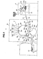
- a digital printing apparatus 1 (sheet processing apparatus) according to this embodiment includes a sheet feed device 2 (sheet supply device), a digital printing unit 3 (processing unit), and a sheet delivery device 4 (sheet discharge device), as shown in Fig. 1 .
- the sheet feed device 2 includes a pile board 21 on which a plurality of sheets S1 are stacked, and a sucker device 23 which conveys the top sheet S1 on the pile board 21 onto a feeder board FB.
- the sucker device 23 includes a pair of suction ports 23a and 23b, which are connected to a negative pressure source 25 via a continuous supply valve 26 and an intermittent supply valve 27.
- the continuous supply valve 26 and intermittent supply valve 27 enable/disable, at different timings, the suction operation of the suction ports 23a and 23b using a negative pressure from the negative pressure source 25.
- a swing arm shaft pregripper 31f is disposed on the distal end side of the feeder board FB in the sheet conveyance direction.
- the swing arm shaft pregripper 31f is swingably supported on a frame 3a of the digital printing unit 3, and includes a gripper device (not shown) which grips and holds the leading edge (front edge) of the sheet S1 as its one edge.
- a feed-side transfer cylinder 32 is opposed to the swing arm shaft pregripper 31f, and rotatably supported on the frame 3a.
- a gripper device 32a which holds the leading edge of the sheet S1, transferred by a gripper device of the swing arm shaft pregripper 31f, in a gripped state is provided on the feed-side transfer cylinder 32.
- the swing arm shaft pregripper 31f and feed-side transfer cylinder 32 constitute an upstream sheet conveyance device.
- the gripper device is formed by a plurality of grippers aligned in the cylinder axis direction with predetermined gaps between them.
- a printing cylinder 33 (second conveyance unit) serving as a downstream transport cylinder is disposed on the downstream side of the swing arm shaft pregripper 31f in the sheet conveyance direction to be in contact with the feed-side transfer cylinder 32.
- the printing cylinder 33 is rotatably supported on the frame 3a, and has a diameter three times that of the feed-side transfer cylinder 32.
- the printing cylinder 33 includes printing cylinder gripper devices 33a, 33b, and 33c (second holders) which hold the leading edge of the sheet S1 upon receiving it from the gripper device 32a of the feed-side transfer cylinder 32, and support surfaces 33d, 33e, and 33f which are provided in correspondence with the printing cylinder gripper devices 33a, 33b, and 33c, and support the sheet S1.
- the printing cylinder 33 is implemented by a triple-diameter cylinder provided with three pairs of printing cylinder gripper devices 33a, 33b, and 33c and support surfaces 33d, 33e, and 33f.
- the printing cylinder gripper devices 33a, 33b, and 33c are provided at positions 120° out of phase with each other in the circumferential direction.
- An inkjet nozzle portion 34 is opposed to the circumferential surface of the printing cylinder 33 on the downstream side of the contact portion of the printing cylinder 33 with the feed-side transfer cylinder 32 in the sheet conveyance direction.
- the inkjet nozzle portion 34 includes a plurality of inkjet nozzle heads 34a to 34d (to be referred to as ink heads hereinafter) which are juxtaposed in the sheet conveyance direction along the circumferential surface of the printing cylinder 33, and store inks of different colors.
- Each of the ink heads 34a to 34d is oriented in a direction perpendicular to the circumferential surface of the printing cylinder 33.
- the ink heads 34a to 34d are arranged in proximity to the printing cylinder 33 to have small gaps with the sheet S1 having its entire surface sucked by the support surfaces 33d, 33e, and 33f.
- the printing cylinder 33 and inkjet nozzle portion 34 constitute a sheet printing device.
- An ink drying lamp 35 is opposed to the printing cylinder 33 on the downstream side of a printing region 33K, printed by the inkjet nozzle portion 34 of the printing cylinder 33, in the sheet conveyance direction, and serves as a drying device which irradiates the sheet S1 with light such as infrared or ultraviolet rays to dry ink printed on the sheet S1. Note that drying includes applying thermal energy to the ink to evaporate the moisture of the ink, and curing the ink.
- the printing cylinder 33 is arranged on the downstream side of the inkjet nozzle portion 34 in the sheet conveyance direction to be in contact with a delivery-side transfer cylinder 36 rotatably supported on the frame 3a.
- the delivery-side transfer cylinder 36 has a gripper device 36a which holds the leading edge of the sheet S1, conveyed by the printing cylinder 33, upon receiving it from the printing cylinder gripper devices 33a, 33b, and 33c.
- a delivery-side transfer cylinder 37 (fourth conveyance unit) serving as an upstream transport cylinder is arranged on the downstream side of the contact portion of the delivery-side transfer cylinder 36 with the printing cylinder 33 in the sheet conveyance direction to be in contact with the delivery-side transfer cylinder 36.
- the delivery-side transfer cylinder 37 is rotatably supported on the frame 3a.
- the delivery-side transfer cylinder 37 has a gripper device 37a (upstream gripper device) which receives and holds the leading edge of the sheet S1 conveyed by the delivery-side transfer cylinder 36.
- a delivery cylinder 38 is arranged on the downstream side of the contact portion of the delivery-side transfer cylinder 37 with the delivery-side transfer cylinder 36 in the sheet conveyance direction to be in contact with the delivery-side transfer cylinder 37.
- the delivery cylinder 38 is rotatably supported on the frame 3a.
- the delivery cylinder 38 has a gripper device 38a (downstream gripper device) which receives and holds the leading edge of the sheet S1 conveyed by the delivery-side transfer cylinder 37.
- a belt conveyor-shaped delivery belt 40 which conveys the sheet S1 is disposed below the delivery cylinder 38.
- a pile board 41 which stacks sheets S1 having undergone a digital printing process by the digital printing unit 3 is provided on the leading edge side of the delivery belt 40 in the sheet conveyance direction.
- the delivery cylinder 38, delivery belt 40, and pile board 41 constitute the sheet delivery device 4. Also, the path of the sheet S1 conveyed by the delivery cylinder 38 and delivery belt 40 constitutes a sheet discharge path.
- a pre-reversal double-diameter cylinder 39 (first conveyance unit) serving as a transport cylinder is arranged on the downstream side of the contact portion of the delivery-side transfer cylinder 37 with the delivery cylinder 38 in the sheet conveyance direction to be in contact with the delivery-side transfer cylinder 37.
- the pre-reversal double-diameter cylinder 39 is rotatably supported on the frame 3a.
- the pre-reversal double-diameter cylinder 39 includes a gripper device 39a (first holder) which is implemented by a double-diameter cylinder with a diameter twice that of the delivery-side transfer cylinder 37, and receives and holds the leading edge of the sheet S1 conveyed by the delivery-side transfer cylinder 37.
- the pre-reversal double-diameter cylinder 39 also includes a circumferential surface 39c (support surface) which supports the entire surface of the sheet S1 with its leading edge held by the gripper device 39a.
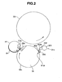
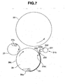
- a reversing swing arm shaft pregripper 31b (third conveyance unit) having a reversing gripper device 31bt (third holder) which receives and holds the trailing edge (rear edge) of the sheet S1 as its other edge is opposed to the pre-reversal double-diameter cylinder 39 on the downstream side of the contact portion of the pre-reversal double-diameter cylinder 39 with the delivery-side transfer cylinder 37 in the sheet conveyance direction, as shown in Fig. 2 .
- a plurality of swing arms 202 are fixed to a reversing swing arm shaft 201 with predetermined gaps between them in the cylinder axis direction.
- the reversing swing arm shaft 201 is pivotally supported on the frame 3a.
- a swing arm gripper 203 is pivotally attached to the distal end of each of the plurality of swing arms 202 through a gripper shaft 203a.
- a gripper pad 205 is provided at a position at which it is opposed to each swing arm gripper 203, and is attached to a gripper pad holding portion 204 fixed to the distal ends of the swing arms 202.
- a plurality of sets of swing arm grippers 203 and gripper pads 205 constitute the reversing gripper device 31bt which grips and holds the trailing edge of the sheet S1.
- the reversing gripper device 31bt, swing arms 202, reversing swing arm shaft 201, and gripper pad holding portion 204 constitute the reversing swing arm shaft pregripper 31b.
- the reversing swing arm shaft pregripper 31b is supported to be swingable between a reception position (a broken line in Fig. 1 ), at which it receives the sheet S1 from the pre-reversal double-diameter cylinder 39, and a transfer position (a solid line in Fig. 1 ), at which it transfers by a gripping change the sheet S1 onto the printing cylinder 33, by pivoting the pivotal reversing swing arm shaft 201.
- the reversing swing arm shaft pregripper 31b is opposed to the printing cylinder 33 on the downstream side of the contact portion of the printing cylinder 33 with the delivery-side transfer cylinder 36 in the rotation direction of the printing cylinder 33, and on the upstream side of the contact portion of the printing cylinder 33 with the feed-side transfer cylinder 32 in the rotation direction of the printing cylinder 33.
- a plurality of groove-shaped recessed portions 39b are formed in the circumferential surface 39c of the pre-reversal double-diameter cylinder 39, pivotally supported on the frame 3a, with gaps between them in the axial direction to extend circumferentially, as shown in Fig. 3 .
- the recessed portions 39b are opposed to the gripper device 37a of the delivery-side transfer cylinder 37, and the reversing gripper device 31bt of the reversing swing arm shaft pregripper 31b.
- the pre-reversal double-diameter cylinder 39 has a driving system independent of those of, for example, the printing cylinder 33, delivery-side transfer cylinder 37, and reversing swing arm shaft pregripper 31b, and is driven independently of the remaining cylinders by an independent driving motor 254 which independently drives it. Note that the pre-reversal double-diameter cylinder 39, reversing swing arm shaft pregripper 31b, and printing cylinder 33 constitute the sheet conveyance device.
- the operation of the gripper device 37a of the delivery-side transfer cylinder 37 is controlled so as to selectively transfer the sheet S1 to the gripper device 38a of the delivery cylinder 38, and the gripper device 39a of the pre-reversal double-diameter cylinder 39. Also, the operation of the gripper device 38a of the delivery cylinder 38 is controlled so as to selectively receive the leading edge of the sheet S1 conveyed by the delivery-side transfer cylinder 37.
- the delivery-side transfer cylinders 36 and 37, pre-reversal double-diameter cylinder 39, and reversing swing arm shaft pregripper 31b constitute a sheet reversing path used to turn and convey the sheet S1.
- the sheet reversing path is used to receive the sheet S1 from the printing cylinder 33, and turn and transfer the sheet S1 onto the printing cylinder 33.
- the gripper device 37a of the delivery-side transfer cylinder 37, and the gripper device 38a of the delivery cylinder 38 constitute a sheet conveyance path switching device which selectively switches the path of the sheet S1 between the sheet reversing path and the sheet discharge path.
- the digital printing apparatus 1 includes a control unit 251 having a CPU (Central Processing Unit) configuration which controls the overall printing operation, as shown in Fig. 4 .
- the control unit 251 is connected to a sheet size input unit 252 which receives the size of the sheet S1, a single-/double-sided printing mode input unit 253 (printing condition input unit) which selects a single- or double-sided printing mode, the independent driving motor 254 (independent driving unit) which independently drives the pre-reversal double-diameter cylinder 39, and a prime motor 255 (device driving unit) which drives the entire printing press.
- the prime motor 255 interlocks and drives the driving system for the printing press other than the pre-reversal double-diameter cylinder 39.
- the continuous supply valve 26 is actuated. With this operation, the suction ports 23a and 23b suck the sheet S1 on the pile board 21, and convey it onto the feeder board FB, as shown in Fig. 1 .
- the independent driving motor is controlled by the control unit 251 to stop the rotation of the pre-reversal double-diameter cylinder 39. This suppresses wasteful power consumption to allow energy saving.
- the continuous supply valve 26 opens every time the same number of sheets S1 as the numbers of printing cylinder gripper devices 33a, 33b, and 33c of the printing cylinder 33 are supplied during 360° rotation of the printing cylinder 33, that is, at each timing (period) at which the printing cylinder gripper devices 33a, 33b, and 33c in the printing cylinder 33, and the gripper device 32a of the feed-side transfer cylinder 32 are opposed to each other.
- a negative pressure is supplied from the negative pressure source 25 to the suction ports 23a and 23b to perform suction.
- the leading edge of the sheet S1 conveyed by the feeder board FB is held by the gripper device of the swing arm shaft pregripper 31f, and the sheet S1 is conveyed onto the feed-side transfer cylinder 32 upon a swing of the swing arm shaft pregripper 31f.
- the leading edge of the sheet S1 conveyed onto the feed-side transfer cylinder 32 is transferred by a gripping change to the gripper device 32a of the feed-side transfer cylinder 32.
- the leading edge of the sheet S1 conveyed with rotation of the feed-side transfer cylinder 32 is transferred by a gripping change from the gripper device 32a of the feed-side transfer cylinder 32 to one of the printing cylinder gripper devices 33a, 33b, and 33c of the printing cylinder 33, and the sheet S1 is conveyed with rotation of the printing cylinder 33.
- a suction force acts on suction holes 33g on the downstream side in the rotation direction from a suction start position 33i, so the entire surface of the sheet S1 is sucked to and brought into tight contact with the support surfaces 33d, 33e, and 33f as the sheet S1 passes through the suction start position 33i.
- a digital printing process is performed on the obverse surface of the sheet S1 conveyed by the printing cylinder 33 by discharging minute drops of ink from the ink heads 34a to 34d of the inkjet nozzle portion 34.
- the sheet S1 is in tight contact with the support surface of the printing cylinder 33, and is therefore conveyed while minute intervals with the ink heads 34a to 34d are maintained. Ink discharged while these minute intervals are maintained can be adhered to the sheet S1 with high accuracy, thereby allowing high-quality printing.
- the ink on the sheet S1 printed by the inkjet nozzle portion 34 dries with light emitted by the ink drying lamp 35 when the sheet S1 passes between the printing cylinder 33 and the ink drying lamp 35.
- the sheet S1 is then conveyed onto the delivery-side transfer cylinder 36.
- the leading edge of the sheet S1 is transferred by a gripping change from the printing cylinder gripper devices 33a to 33c of the printing cylinder 33 to the gripper device 36a of the delivery-side transfer cylinder 36, as shown in Fig. 5A .
- the leading edge of the sheet S1 passes through a suction end position 33j, so no suction force acts from the suction holes 33g. This makes it possible to easily peel the sheet S1 off the support surfaces 33d, 33e, and 33f to allow a smooth gripping change.
- the leading edge of the sheet S1 held by the gripper device 36a of the delivery-side transfer cylinder 36 is transferred by a gripping change from the gripper device 36a of the delivery-side transfer cylinder 36 to the gripper device 37a of the delivery-side transfer cylinder 37 in the contact portion between the delivery-side transfer cylinders 36 and 37, as shown in Fig. 5B .
- the gripper device 37a of the delivery-side transfer cylinder 37 cancels holding of the leading edge of the sheet S1
- the gripper device 38a of the delivery cylinder 38 grips and holds the leading edge of the sheet S1 at the same time.
- the sheet S1 printed on its one surface is transferred from the delivery-side transfer cylinder 37 onto the delivery cylinder 38, and conveyed.
- Holding, by the gripper device 38a, of the sheet S1 transferred onto the delivery cylinder 38 is canceled at the timing at which the gripper device 38a of the delivery cylinder 38 is positioned above the delivery belt 40, and is placed on the delivery belt 40.
- the sheet S1 placed on the delivery belt 40 is conveyed as the delivery belt 40 travels, and the sheet S1 having undergone a digital printing process on its obverse surface is discharged onto the pile board 41 of the sheet delivery device 4.
- the pre-reversal double-diameter cylinder 39 is kept stopped without rotation, and the delivery-side transfer cylinder 37 and reversing swing arm shaft pregripper 31b provided on the upstream and downstream sides of the pre-reversal double-diameter cylinder 39 operate, but the recessed portions 39b in the pre-reversal double-diameter cylinder 39 are opposed to the gripper device 37a of the delivery-side transfer cylinder 37, and the reversing gripper device 31bt of the reversing swing arm shaft pregripper 31b, so the gripper devices 37a and 31bt do not interfere with the pre-reversal double-diameter cylinder 39.
- the control unit 251 actuates the intermittent supply valve 27 to make the suction ports 23a and 23b suck and convey the sheet S1 on the pile board 21 onto the feeder board FB.
- the intermittent supply valve 27 is controlled at the timing at which the sheets S1 are alternately supplied so as to open, close, open, close,..., at the timing of continuous supply, that is, the timing at which the printing cylinder gripper devices 33a, 33b, and 33c of the printing cylinder 33, and the gripper device 32a of the feed-side transfer cylinder 32 are opposed to each other.
- This period is twice that of continuous supply.
- supply of the sheets S1 so that the printing cylinder gripper devices 33a, 33b, and 33c of the printing cylinder 33 alternately grip the sheets S1 will be referred to as intermittent sheet feed hereinafter, and the period at which the intermittent supply valve 27 opens/closes in intermittent sheet feed will be referred to as a second period hereinafter.
- the sucker device 23 conveys the sheets S1 onto the feeder board FB at the second period.
- the sheet S1 fed onto the feeder board FB by the sucker device 23 is transferred onto the printing cylinder 33 through the swing arm shaft pregripper 31f and feed-side transfer cylinder 32 in the same way as in the single-sided printing mode.
- the printing cylinder gripper devices 33a to 33c of the printing cylinder 33 receive the sheet S1 alternately conveyed from the feed-side transfer cylinder 32.
- the sheet S1 transferred onto the printing cylinder 33 is conveyed to the inkjet nozzle portion 34, and obverse surface printing is performed on one surface (obverse surface).
- the control unit 251 prints on the sheet S1 alternately held by the printing cylinder gripper devices 33a to 33c of the printing cylinder 33, based on a phase signal from the rotary encoder 84.
- the ink heads 34a to 34d of the inkjet nozzle portion 34 are controlled so as not to print on the support surfaces 33d to 33f corresponding to the printing cylinder gripper devices 33a to 33c which do not hold the sheet S1.
- control unit 251 controls the conveyance path switching device 82 so that the sheet S1 printed on its obverse surface by the inkjet nozzle portion 34 is transferred onto the pre-reversal double-diameter cylinder 39 without transferring it from the delivery-side transfer cylinder 37 onto the delivery cylinder 38.
- the grippers of the gripper device 37a of the delivery-side transfer cylinder 37 are kept closed without opening to maintain the state in which the gripper device 37a holds the leading edge of the sheet S1.
- the grippers of the gripper device 38a of the delivery cylinder 38 are kept open without closing.
- the leading edge of the sheet S1 conveyed by the delivery-side transfer cylinder 37 is held by closing the grippers of the gripper device 39a of the pre-reversal double-diameter cylinder 39 in the contact portion between the delivery-side transfer cylinder 37 and the pre-reversal double-diameter cylinder 39. At the same time, holding of the leading edge of the sheet S1 is canceled by opening the grippers of the gripper device 37a of the delivery-side transfer cylinder 37. With this operation, the leading edge of the sheet S1 is transferred by a gripping change from the gripper device 37a of the delivery-side transfer cylinder 37 to the gripper device 39a of the pre-reversal double-diameter cylinder 39, as shown in Fig. 5C .
- the gripper device 37a of the delivery-side transfer cylinder 37 passes through the grooves of the recessed portions 39b to prevent the circumferential surface of the pre-reversal double-diameter cylinder 39 from suffering damage.
- the sheet S1 conveyed with rotation of the pre-reversal double-diameter cylinder 39 is conveyed with rotation of the pre-reversal double-diameter cylinder 39, as shown in Fig. 5D .
- the reversing swing arm shaft pregripper 31b swings from a transfer position (solid line) to a reception position (broken line) to make the reversing gripper device 31bt of the reversing swing arm shaft pregripper 31b hold the trailing edge of the sheet S1, and holding of the leading edge of the sheet S1 by the gripper device 39a of the pre-reversal double-diameter cylinder 39 is canceled at the same time.
- the sheet S1 is transferred by a gripping change from the pre-reversal double-diameter cylinder 39 to the reversing swing arm shaft pregripper 31b.
- the reversing gripper device 31bt of the reversing swing arm shaft pregripper 31b passes through the grooves of the recessed portions 39b to prevent the circumferential surface of the pre-reversal double-diameter cylinder 39 from suffering damage.
- the pre-reversal double-diameter cylinder 39 receives the sheet S1 from the delivery-side transfer cylinder 37, and transfers it to the reversing swing arm shaft pregripper 31b (driving control of the pre-reversal double-diameter cylinder 39) will be described in detail. If the dimension in the conveyance direction, which is input to the sheet size input unit 252, is a standard size (middle-sized paper), the control unit 251 controls the independent driving motor 254 to rotate the pre-reversal double-diameter cylinder 39 at a reference speed.
- the reference speed means the rotation speed at which the pre-reversal double-diameter cylinder 39 rotates at a peripheral speed equal to those of the printing cylinder 33 and delivery-side transfer cylinder 37.
- the pre-reversal double-diameter cylinder 39 rotates at the reference speed with no difference in peripheral speed between the printing cylinder 33 and the delivery-side transfer cylinder 37.
- Fig. 6 shows the rotation speed of the pre-reversal double-diameter cylinder 39 when the digital printing apparatus 1 operates at a steady speed, that is, the printing cylinder 33 and delivery-side transfer cylinder 37 rotate at a constant speed.
- Fig. 6 shows the time or the phase of the digital printing apparatus 1 on the abscissa, and the rotation speed of the pre-reversal double-diameter cylinder 39 on the ordinate.
- t0 is the reception timing at which the leading edge of the sheet S1 is transferred by a gripping change from the delivery-side transfer cylinder 37 to the pre-reversal double-diameter cylinder 39
- t1 is the first adjustment start timing of the rotation speed of the pre-reversal double-diameter cylinder 39
- t2 is the first adjustment end timing of the rotation speed of the pre-reversal double-diameter cylinder 39
- t3 is the transfer timing at which the trailing edge of the sheet S1 is transferred by a gripping change from the pre-reversal double-diameter cylinder 39 to the reversing swing arm shaft pregripper 31b.
- t4 is the second adjustment start timing of the rotation speed of the pre-reversal double-diameter cylinder 39
- t5 is the second adjustment end timing of the rotation speed of the pre-reversal double-diameter cylinder 39
- t6 is the reception timing at which the leading edge of the sheet S1 is transferred by a gripping change from the delivery-side transfer cylinder 37 to the pre-reversal double-diameter cylinder 39 again.
- timings t0 to t6 indicate the times or the phases of the digital printing apparatus 1, and reception timings t6 and t0 are identical when the timing is represented as a phase. Also, the interval from first adjustment start timing t1 to first adjustment end timing t2 is defined as a first speed adjustment region, and that from second adjustment start timing t4 to second adjustment end timing t5 is defined as a second speed adjustment region.
- the pre-reversal double-diameter cylinder 39 is rotated by the independent driving motor 254 at a constant speed v0 (reference speed) with no change in speed from reception timing t0 to reception timing t6, as indicated by bold lines in Fig. 6 .
- the pre-reversal double-diameter cylinder 39 must be rotated at a peripheral speed equal to those of the printing cylinder 33 and delivery-side transfer cylinder 37.
- the printing cylinder 33 and delivery-side transfer cylinder 37 are driven by the prime motor 255, while the pre-reversal double-diameter cylinder 39 is rotated at a constant speed v0 by the independent driving motor 254.
- the pre-reversal double-diameter cylinder 39 is rotated by the independent driving motor 254 at a peripheral speed which is equal to those of the printing cylinder 33 and delivery-side transfer cylinder 37 and different from the reference speed.
- the gripper device 37a of the delivery-side transfer cylinder 37, and the gripper device 39a of the pre-reversal double-diameter cylinder 39 are opposed to each other, so the leading edge of a sheet S1 with the standard size is transferred by a gripping change, and the sheet S1 is wound around the circumferential surface 39c of the pre-reversal double-diameter cylinder 39 and conveyed, as shown in Fig. 2 .
- the reversing gripper device 31bt of the reversing swing arm shaft pregripper 31b grips the trailing edge of the sheet S1
- the gripper device 39a of the pre-reversal double-diameter cylinder 39 cancels holding of the leading edge of the sheet S1
- the sheet S1 is transferred by a gripping change from the pre-reversal double-diameter cylinder 39 to the reversing swing arm shaft pregripper 31b.
- the reversing swing arm shaft pregripper 31b then swings from the reception position to the transfer position, and transfers the turned sheet S1 onto the printing cylinder 33, as shown in Fig. 8 .
- control unit 251 controls the pre-reversal double-diameter cylinder 39 to simply rotate at the reference speed through the independent driving motor 254, so no change in speed with respect to the reference speed occurs.
- control unit 251 rotates the pre-reversal double-diameter cylinder 39 at a reference speed (speed v0) equal to that in the case of the sheet S1 with the standard size (middle-sized paper), as indicated by solid lines in Fig. 6 .
- the speed of the pre-reversal double-diameter cylinder 39 is controlled to gradually increase with respect to the reference speed from first adjustment start timing t1, and return to the reference speed at first adjustment end timing t2. Then, in the second speed adjustment region, the speed of the pre-reversal double-diameter cylinder 39 is controlled to gradually decrease with respect to the reference speed from second adjustment start timing t4, and return to the reference speed at second adjustment end timing t5.
- control unit 251 rotates the pre-reversal double-diameter cylinder 39 at the reference speed (speed v0) in the interval from reception timing t0 to first adjustment start timing t1, that from first adjustment end timing t2 to second adjustment start timing t4, and that from second adjustment end timing t5 to reception timing t6.
- the pre-reversal double-diameter cylinder 39 receives the sheet S1a from the delivery-side transfer cylinder 37 and transfers it to the reversing swing arm shaft pregripper 31b while rotating at the reference speed. This allows a reliable gripping change of the sheet S1a.
- the gripper device 39a of the pre-reversal double-diameter cylinder 39 is set at a position, indicated by a broken line in Fig. 8 , at transfer timing t3 as the pre-reversal double-diameter cylinder 39 rotates while its rotation speed is kept at the constant speed v0 (reference speed).
- the trailing edge of the sheet S1a has not yet reached the reversing gripper device 31bt of the reversing swing arm shaft pregripper 31b set at the reception position, and therefore cannot be gripped by the reversing gripper device 31bt.
- the pre-reversal double-diameter cylinder 39 in the first speed adjustment region, is accelerated from the reference speed to advance the phase of the pre-reversal double-diameter cylinder 39 more than that of the digital printing apparatus 1, thereby setting the gripper device 39a of the pre-reversal double-diameter cylinder 39 at a position, indicated by a solid line in Fig. 8 , at transfer timing t3.
- the trailing edge of the sheet S1a is opposed to the reversing gripper device 31bt of the reversing swing arm shaft pregripper 31b set at the reception position.
- the trailing edge of the sheet S1a is gripped by the reversing gripper device 31bt of the reversing swing arm shaft pregripper 31b, and holding of the leading edge of the sheet S1a is canceled by the gripper device 39a of the pre-reversal double-diameter cylinder 39 at the same time.
- the sheet S1a is transferred by a gripping change from the pre-reversal double-diameter cylinder 39 to the reversing swing arm shaft pregripper 31b.
- the reversing swing arm shaft pregripper 31b then swings from the reception position to the transfer position, and transfers the turned sheet S1a onto the printing cylinder 33, as shown in Fig. 5E .
- the control unit 251 rotates the pre-reversal double-diameter cylinder 39 at the speed v0 (reference speed). Then, in the second speed adjustment region, the pre-reversal double-diameter cylinder 39 is decelerated from the reference speed to retard the phase of the pre-reversal double-diameter cylinder 39, which has advanced more than that of the digital printing apparatus 1.
- the gripper device 39a of the pre-reversal double-diameter cylinder 39 is opposed to the gripper device 37a of the delivery-side transfer cylinder 37, as shown in Fig. 2 .
- the leading edge of the sheet S1a is transferred by a gripping change from the gripper device 37a of the delivery-side transfer cylinder 37 to the gripper device 39a of the pre-reversal double-diameter cylinder 39.
- control unit 251 increases/decreases the rotation speed of the pre-reversal double-diameter cylinder 39 to control (adjust) the phase of the pre-reversal double-diameter cylinder 39 relative to that of the digital printing apparatus 1 in the first and second speed adjustment regions, that do not influence reception timing t0, transfer timing t3, and reception timing t6 at which a gripping change of the sheet S1a (maximum-sized paper) is done.
- the leading edge of the sheet S1a can reliably be transferred by a gripping change from the delivery-side transfer cylinder 37 to the pre-reversal double-diameter cylinder 39 by increasing/decreasing the rotation speed of the pre-reversal double-diameter cylinder 39.
- the trailing edge of the sheet S1a can reliably be transferred by a gripping change from the pre-reversal double-diameter cylinder 39 to the reversing swing arm shaft pregripper 31b.
- the control unit 251 rotates the pre-reversal double-diameter cylinder 39 at a reference speed (speed v0) equal to that in the case of the sheet S1 with the standard size (middle-sized paper), as indicated by broken lines in Fig. 6 .
- the speed of the pre-reversal double-diameter cylinder 39 is controlled to gradually decrease with respect to the reference speed from first adjustment start timing t1, and return to the reference speed at first adjustment end timing t2. Then, in the second speed adjustment region, the speed of the pre-reversal double-diameter cylinder 39 is controlled to gradually increase with respect to the reference speed from second adjustment start timing t4, and return to the reference speed at second adjustment end timing t5.
- control unit 251 rotates the pre-reversal double-diameter cylinder 39 at the reference speed (speed v0) in the interval from reception timing t0 to first adjustment start timing t1, that from first adjustment end timing t2 to second adjustment start timing t4, and that from second adjustment end timing t5 to reception timing t6.
- the pre-reversal double-diameter cylinder 39 performs reception and transfer operations while rotating at the reference speed, thus allowing a reliable gripping change of the sheet S1b.
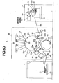
- the gripper device 39a of the pre-reversal double-diameter cylinder 39 is set at a position, indicated by a broken line in Fig. 9 , at transfer timing t3 as the pre-reversal double-diameter cylinder 39 rotates while its rotation speed is kept at the constant speed v0 (reference speed).
- the trailing edge of the sheet S1b has already passed through the reversing gripper device 31bt of the reversing swing arm shaft pregripper 31b set at the reception position, and therefore cannot be gripped by the swing arm gripper 203.
- the pre-reversal double-diameter cylinder 39 in the first speed adjustment region, is decelerated from the reference speed to retard the phase of the pre-reversal double-diameter cylinder 39 more than that of the digital printing apparatus 1, thereby setting the gripper device 39a of the pre-reversal double-diameter cylinder 39 at a position, indicated by a solid line in Fig. 9 , at transfer timing t3.
- the trailing edge of the sheet S1b is opposed to the reversing gripper device 31bt of the reversing swing arm shaft pregripper 31b set at the reception position.
- the trailing edge of the sheet S1b is gripped by the reversing gripper device 31bt of the reversing swing arm shaft pregripper 31b, and holding of the leading edge of the sheet S1b is canceled by the gripper device 39a of the pre-reversal double-diameter cylinder 39 at the same time.
- the sheet S1b is transferred by a gripping change from the pre-reversal double-diameter cylinder 39 to the reversing swing arm shaft pregripper 31b.
- the reversing swing arm shaft pregripper 31b then swings from the reception position to the transfer position, and transfers the turned sheet S1b onto the printing cylinder 33, as shown in Fig. 5E .
- the control unit 251 rotates the pre-reversal double-diameter cylinder 39 at the speed v0 (reference speed). Then, in the second speed adjustment region, the pre-reversal double-diameter cylinder 39 is accelerated from the reference speed to advance the phase of the pre-reversal double-diameter cylinder 39, which has retarded more than that of the digital printing apparatus 1.
- the gripper device 39a of the pre-reversal double-diameter cylinder 39 is opposed to the gripper device 37a of the delivery-side transfer cylinder 37, as shown in Fig. 2 .
- the leading edge of the sheet S1b is transferred by a gripping change from the gripper device 37a of the delivery-side transfer cylinder 37 to the gripper device 39a of the pre-reversal double-diameter cylinder 39.
- control unit 251 increases/decreases the rotation speed of the pre-reversal double-diameter cylinder 39 to control (adjust) the phase of the pre-reversal double-diameter cylinder 39 relative to that of the digital printing apparatus 1 in the first and second speed adjustment regions, that do not influence reception timing t0, transfer timing t3, and reception timing t6 at which a gripping change of the sheet S1b (minimum-sized paper) is done.
- the leading edge of the sheet S1b can reliably be transferred by a gripping change from the delivery-side transfer cylinder 37 to the pre-reversal double-diameter cylinder 39 by increasing/decreasing the rotation speed of the pre-reversal double-diameter cylinder 39.
- the trailing edge of the sheet S1b can reliably be transferred by a gripping change from the pre-reversal double-diameter cylinder 39 to the reversing swing arm shaft pregripper 31b.
- the sheet S1 (sheet S1, S1a, or S1b) with its trailing edge leading is conveyed onto the printing cylinder 33.
- the trailing edge of the turned sheet S1 is transferred by a gripping change from the reversing gripper device 31bt of the reversing swing arm shaft pregripper 31b to one of the gripper devices 33a to 33c.
- the gripper devices 33a to 33c of the printing cylinder 33 alternately hold a new sheet S1 conveyed from the feed-side transfer cylinder 32.
- the reversing swing arm shaft pregripper 31b is positioned at the transfer position at the timing at which it is opposed to the printing cylinder gripper devices 33a to 33c which hold no new sheet S1, and the trailing edge of the sheet S1 is transferred from the reversing gripper device 31bt to the printing cylinder gripper devices 33a to 33c.
- the trailing edge of the turned sheet S1 transferred from the reversing gripper device 31bt of the reversing swing arm shaft pregripper 31b is held and conveyed by the gripper devices 33a to 33c of the printing cylinder 33 while the surface (the obverse surface having undergone a digital printing process) of the sheet S1, which has already undergone a digital printing process by the inkjet nozzle portion 34, is in contact with the support surfaces 33d, 33e, and 33f of the printing cylinder 33, and the surface (the reverse surface having undergone no digital printing process) of the sheet S1, which has not yet undergone a digital printing process, is exposed.
- the inkjet nozzle portion 34 performs a digital printing process on the reverse surface of the sheet S1 conveyed in tight contact with the circumferential surface of the printing cylinder 33 in a turned state.
- the control unit 251 controls the inkjet nozzle heads 34a to 34d of the inkjet nozzle portion 34 to perform reverse printing on the turned sheet S1 transferred from the reversing gripper device 31bt of the reversing swing arm shaft pregripper 31b, and perform obverse printing on the new sheet S1 alternately held by the printing cylinder gripper devices 33a to 33c of the printing cylinder 33. With this operation, the inkjet nozzle heads 34a to 34d alternately perform obverse printing and reverse printing in correspondence with the new sheet S1 and turned sheet S1 alternately held by the printing cylinder 33.
- the sheet S1 having undergone reverse printing on its reverse surface is discharged from the delivery belt 40 onto the pile board 41 sequentially through the delivery-side transfer cylinders 36 and 37, and delivery cylinder 38, as in the single-sided printing mode.
- the independent driving motor 254 is controlled to increase/decrease (adjust) the rotation speed of the pre-reversal double-diameter cylinder 39 based on the dimension in the sheet conveyance direction. It is therefore possible to reliably receive the leading edge of the sheet S1 from the delivery-side transfer cylinder 37 to the pre-reversal double-diameter cylinder 39, and transfer the trailing edge of the sheet S1 from the pre-reversal double-diameter cylinder 39 to the reversing swing arm shaft pregripper 31b. This obviates the need for mechanical adjustment that accompanies a change in sheet size to relieve the operator's burden. This also obviates the need for a preparatory operation to improve the productivity.
- the sheet S1 is sequentially transferred to the feed-side transfer cylinder 32, printing cylinder 33, delivery-side transfer cylinders 36 and 37, pre-reversal double-diameter cylinder 39, and reversing swing arm shaft pregripper 31b by a gripping change by the gripper devices.
- This makes it possible to obtain high registration accuracy and high obverse/reverse registration accuracy of the obverse and reverse surfaces of the sheet S1 in the conveyance direction or widthwise direction of the sheet S1, thus improving the printing quality of the sheet S1.
- the second embodiment is the same as the first embodiment except for the configuration of the control block of the digital printing apparatus 1. Only a control block of a digital printing apparatus 200 according to the second embodiment will be described below.
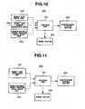
- the digital printing apparatus 200 includes a control unit 351 having a CPU configuration which controls the overall printing operation, as shown in Fig. 10 .
- the control unit 351 is connected to a sheet size input unit 252 which receives the sheet size as standard information, a sheet size error detection unit 255 which includes a photoelectric sensor arranged near a printing cylinder 33, a single-/double-sided printing mode input unit 253 which selects a single- or double-sided printing mode, an independent driving motor 254, and a prime motor 255.
- the sheet size error detection unit 255 detects an error of the sheet size, that is, the dimension in the conveyance direction, which is actually printed for standard data input via the sheet size input unit 252.
- the control unit 351 receives signals output from the sheet size input unit 252, sheet size error detection unit 255, and single-/double-sided printing mode input unit 253 to control the independent driving motor 254. Differences from the first embodiment lie in that the sheet size input unit 252 receives the sheet size as standard information, and the sheet size error detection unit 255 is provided.
- the control unit 351 recognizes the sheet S1 as one of a sheet S1 with a standard size (middle-sized paper), a sheet S1a (maximum-sized paper) with a large dimension in the conveyance direction, and a sheet S1b (minimum-sized paper) with a small dimension in the conveyance direction, based on the standard information (middle-sized paper, maximum-sized paper, or minimum-sized paper) of the sheet S1 input to the sheet size input unit 252.
- the sheet size error detection unit 255 detects errors of the sheet sizes (sheet conveyance direction) for three types of standard information for the first sheet S1 (middle-sized paper), sheet S1a (maximum-sized paper), or sheet S1b (minimum-sized paper) supplied for each lot, and sends these errors to the control unit 351.
- the control unit 351 adds/subtracts one (error data corresponding to input standard information) of three types of error data input from the sheet size error detection unit 255 to/from standard information (one of middle-sized paper, maximum-sized paper, and minimum-sized paper), and determines the actual size of the sheet.
- the control unit 351 controls driving of the independent driving motor 254 to increase/decrease the rotation speed of a pre-reversal double-diameter cylinder 39 based on the obtained actual size of the sheet.
- the leading edge of the sheet S1a from a delivery-side transfer cylinder 37 can reliably be received by a gripping change by the pre-reversal double-diameter cylinder 39, regardless of the sheet size. Also, the trailing edge of the sheet S1a can reliably be transferred by a gripping change from the pre-reversal double-diameter cylinder 39 to a reversing swing arm shaft pregripper 31b.
- the sheet size error detection unit 255 may detect only error information for the sent standard information and output it to the control unit 351.
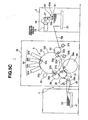
- the digital printing apparatus 300 includes a control unit 451 having a CPU configuration which controls the overall printing operation, as shown in Fig. 11 .
- the control unit 451 is connected to a sheet size detection unit 257 arranged near a printing cylinder 33, a single-/double-sided printing mode input unit 253 which selects a single- or double-sided printing mode, an independent driving motor 254, and a prime motor 255.
- the sheet size detection unit 257 detects the dimension in the conveyance direction (size). A difference from the first embodiment lies in that the sheet size detection unit 257 is provided in place of the sheet size input unit 257.
- the sheet size detection unit 257 detects the dimension, in the conveyance direction, of a sheet S1 conveyed by a pre-reversal double-diameter cylinder 39, and outputs it to the control unit 451.
- the control unit 451 recognizes the dimension of each sheet S1 in the conveyance direction based on the output from the sheet size detection unit 257.
- the control unit 451 controls the independent driving motor 254 to increase/decrease the rotation speed of the pre-reversal double-diameter cylinder 39 based on the measurement data of the sheet S1 detected by the sheet size detection unit 257, that is, the actual size of the sheet S1.
- the leading edge of the sheet S1 from a delivery-side transfer cylinder 37 can reliably be received by a gripping change by the pre-reversal double-diameter cylinder 39, regardless of the sheet size. Also, the trailing edge of the sheet S1 can reliably be transferred by a gripping change from the pre-reversal double-diameter cylinder 39 to a reversing swing arm shaft pregripper 31b.
- a sheet conveyance device is applied to the digital printing apparatus 1 (sheet processing apparatus) in the above-mentioned embodiment, the present invention is not limited to this.
- the sheet conveyance device according to the present invention may also be applied to, for example, an offset print process apparatus, inspection process apparatus, foil transfer process apparatus, and embossing process apparatus as other sheet processing apparatuses.
- the rotation speed of the pre-reversal double-diameter cylinder 39 is increased/decreased when sheets S1a and S1b with sizes in the sheet conveyance direction, which are larger and smaller than the standard size, are conveyed.
- the present invention is not limited to this, and assuming that a sheet S1a with a maximum dimension in the conveyance direction has a standard size, the rotation speed of the pre-reversal double-diameter cylinder 39 may be adjusted when a sheet with a dimension in the sheet conveyance direction, which is smaller than the standard size, is conveyed.
- the rotation speed of the pre-reversal double-diameter cylinder 39 may be adjusted when a sheet with a dimension in the sheet conveyance direction, which is larger than the standard size, is conveyed.
- the printing cylinder 33 implemented by a triple-diameter cylinder is used in the above-mentioned embodiments, the present invention is not limited to this, and a printing cylinder implemented by a double-, quadrupole- or sextuple-diameter cylinder may be used.
Claims (4)
- Bogenfordervorrichtung umfassend:eine erste Fördereinheit (39), die einen ersten Halter (39a) umfasst, der eine Kante eines Bogens (S1, S1a, S1b) hält, und den Bogen, der von dem ersten Halter gehalten wird, fördert;eine zweite Fördereinheit (33), die einen zweiten Halter (33a bis 33c) umfasst, der die eine Kante des Bogens hält, und den Bogen, der von dem zweiten Halter gehalten wird, fördert;eine dritte Fördereinheit (31 b), wobei die dritte Fördereinheit einen dritten Halter (31bt) umfasst, der die andere Kante des Bogens hält, der von der ersten Fördereinheit (39) gefördert wird, und den Bogen, der von dem dritten Halter gehalten wird, fördert;eine unabhängige Antriebseinheit (254), die die erste Fördereinheit unabhängig antreibt;eine Vorrichtungs-Antriebseinheit (255), die die gesamte Vorrichtung einschließlich der zweiten Fördereinheit und der dritten Fördereinheit antreibt; undeine Steuereinheit (251), die die unabhängige Antriebseinheit (254) steuert, um eine Geschwindigkeit anzupassen, bei der die dritte Fördereinheit den Bogen basierend auf einer Abmessung des Bogens in eine Förderrichtung fördert,wobei die erste Fördereinheit einen drehbar gelagerten Transportzylinder umfasst, unddie unabhängige Antriebseinheit einen unabhängigen Antriebsmotor umfasst, der den Transportzylinder unabhängig von einem Vorrichtungs-Antriebssystem antreibt,dadurch gekennzeichnet, dassdie dritte Fördereinheit (31b) gelagert ist, um zwischen einer Aufnahmeposition, an der die dritte Fördereinheit den Bogen von der ersten Fördereinheit (39) empfängt, und einer Übertragungsposition, an der die dritte Fördereinheit den Bogen zu der zweiten Fördereinheit (33) überträgt, schwingbar vorgesehen zu sein, und über ein weiter Umfasseneiner vierten Fördereinheit (37), die an einer stromaufwärts gelegenen Seite des Transportzylinders (39) in einer Bogenförderrichtung angeordnet ist, einen vierten Halter (37a) umfasst, der eine Kante des Bogens hält, und den Bogen, der von dem vierten Halter gehalten wird, zu dem ersten Halter (39a) des Transportzylinders (39) überträgt,wobei die Steuereinheit (251) den unabhängigen Antriebsmotor steuert, um eine Drehgeschwindigkeit des Transportzylinders in Übereinstimmung mit der Abmessung des Bogens in der Förderrichtung anzupassen, so dassdie andere Kante des Bogens, der von dem Transportzylinder (39) gefördert wird, dem dritten Halter (31 bt) gegenüberliegt, wenn die dritte Fördereinheit (31 b) an der Bogenaufnahmeposition festgelegt ist, undder vierte Halter der vierten Fördereinheit dem ersten Halter der ersten Fördereinheit gegenüberliegt, nachdem der Bogen auf den dritten Halter übertragen worden ist.
- Vorrichtung gemäß Anspruch 1, bei der,
wenn die Abmessung des Bogens in der Förderrichtung größer als eine Standardgröße ist, die Steuereinheit (251) ausgelegt ist, um den unabhängigen Antriebsmotor derart zu steuern, um die Drehgeschwindigkeit des Transportzylinders höher als eine Referenzgeschwindigkeit einzustellen, nachdem der Bogen von der vierten Fördereinheit aufgenommen worden ist, und dann die Drehgeschwindigkeit des Transportzylinders geringer als die Referenzgeschwindigkeit einzustellen, nachdem der Bogen von dem Transportzylinder auf die dritte Fördereinheit übertragen worden ist, und
wenn die Abmessung des Bogens in der Förderrichtung kleiner als die Standardgröße ist, die Steuereinheit (251) ausgelegt ist, um den unabhängigen Antriebsmotor derart zu steuern, um die Drehgeschwindigkeit des Transportzylinder niedriger als die Referenzgeschwindigkeit einzustellen, nachdem der Bogen von der vierten Fördereinheit aufgenommen worden ist, und dann die Drehgeschwindigkeit des Transportzylinders höher einzustellen, als die Referenzgeschwindigkeit, nachdem der Bogen von dem Transportzylinder auf die dritte Fördereinheit übertragen worden ist. - Vorrichtung gemäß Anspruch 1, bei der die Steuereinheit (251) ausgelegt ist, um den unabhängigen Antriebsmotor (254) derart zu steuern, um die Drehgeschwindigkeit des Transportzylinders (39) auf eine Referenzgeschwindigkeit einzustellen, wenn der Bogen von dem Transportzylinder (39) auf die dritte Fördereinheit (31b) übertragen wird, und der Bogen von der vierten Fördereinheit (37) auf den Transportzylinder (39) übertragen wird.
- Vorrichtung gemäß Anspruch 1, bei der, wenn die Abmessung des Bogens in der Förderrichtung eine Standardgröße ist, die Steuervorrichtung (251) ausgelegt ist, um den unabhängigen Antriebsmotor (254) derart zu steuern, um den Transportzylinder (39) bei einer Referenzgeschwindigkeit zu drehen.
Applications Claiming Priority (1)
| Application Number | Priority Date | Filing Date | Title |
|---|---|---|---|
| JP2012099556 | 2012-04-25 |
Publications (2)
| Publication Number | Publication Date |
|---|---|
| EP2657025A1 EP2657025A1 (de) | 2013-10-30 |
| EP2657025B1 true EP2657025B1 (de) | 2015-08-19 |
Family
ID=48190678
Family Applications (1)
| Application Number | Title | Priority Date | Filing Date |
|---|---|---|---|
| EP13002145.4A Active EP2657025B1 (de) | 2012-04-25 | 2013-04-24 | Blattfördervorrichtung |
Country Status (4)
| Country | Link |
|---|---|
| US (1) | US9422126B2 (de) |
| EP (1) | EP2657025B1 (de) |
| JP (1) | JP6030979B2 (de) |
| CN (1) | CN103373054B (de) |
Families Citing this family (9)
| Publication number | Priority date | Publication date | Assignee | Title |
|---|---|---|---|---|
| JP6245748B2 (ja) * | 2014-02-12 | 2017-12-13 | 株式会社小森コーポレーション | フレキシブル電子デバイス製造装置 |
| CN107567385B (zh) * | 2015-04-30 | 2020-12-01 | 柯尼格及包尔公开股份有限公司 | 用于依次加工单张纸状基材的方法和机器结构 |
| WO2016181914A1 (ja) * | 2015-05-11 | 2016-11-17 | コニカミノルタ株式会社 | インクジェット記録装置 |
| DE102016207398B3 (de) * | 2015-09-09 | 2016-08-18 | Koenig & Bauer Ag | Maschinenanordnung zum sequentiellen Bearbeiten mehrerer bogenförmiger jeweils eine Vorderseite und eine Rückseite aufweisender Substrate |
| US9446612B1 (en) * | 2015-12-11 | 2016-09-20 | Xerox Corporation | Multiple-gripper architecture for multi-sheet-length digital printing |
| DE102016207397A1 (de) | 2016-04-29 | 2017-11-02 | Koenig & Bauer Ag | Vorrichtung zum Unterschuppen von Bogen |
| DE102016215792B4 (de) | 2016-08-23 | 2020-07-16 | Koenig & Bauer Ag | Maschinenanordnung zum sequentiellen Bearbeiten mehrerer bogenförmiger jeweils eine Vorderseite und eine Rückseite aufweisender Substrate |
| WO2018207260A1 (ja) * | 2017-05-09 | 2018-11-15 | 株式会社Fuji | 対基板作業機 |
| CN117125457B (zh) * | 2023-08-30 | 2024-01-23 | 江苏奕隆机电科技有限公司 | 带有视觉校验功能的电磁阀阀座输送系统 |
Family Cites Families (20)
| Publication number | Priority date | Publication date | Assignee | Title |
|---|---|---|---|---|
| IT1040008B (it) | 1975-07-24 | 1979-12-20 | Cigardi Omc Sa | Sistema e dispositivo per il rove sciamento sequenziale dei fogli su machine da stampa offset da foglio a piu colori |
| US4165689A (en) * | 1975-07-24 | 1979-08-28 | Officine Meccaniche Cigardi S.P.A. | Device for sequential overturning of sheets in multi-color offset printing machines |
| JPS58219058A (ja) | 1982-06-14 | 1983-12-20 | Komori Printing Mach Co Ltd | 反転機構付枚葉輪転印刷機 |
| DE4231257C2 (de) * | 1992-09-18 | 1998-02-26 | Heidelberger Druckmasch Ag | Bogenrotationsdruckmaschine |
| JP3600727B2 (ja) | 1997-03-28 | 2004-12-15 | 大日本スクリーン製造株式会社 | 印刷装置 |
| US6827018B1 (en) * | 1997-09-26 | 2004-12-07 | Heidelberger Druckmaschinen Ag | Device and method for driving a printing machine with multiple uncoupled motors |
| DE19742461C2 (de) * | 1997-09-26 | 2001-05-10 | Heidelberger Druckmasch Ag | Vorrichtung zum Antrieb einer Bogendruckmaschine mit Mehrmotorenantrieb |
| US6311613B1 (en) * | 1998-03-30 | 2001-11-06 | Tohoku Ricoh Co., Ltd. | Stencil printer |
| WO1999061957A1 (en) * | 1998-05-24 | 1999-12-02 | Indigo N.V. | Printing system |
| US6912952B1 (en) * | 1998-05-24 | 2005-07-05 | Hewlett-Packard Indigo B.V. | Duplex printing system |
| JP2002033641A (ja) | 2000-07-17 | 2002-01-31 | Toyo Commun Equip Co Ltd | 二重モード圧電フィルタ及び圧電振動子 |
| DE10152843A1 (de) | 2000-11-29 | 2002-06-13 | Heidelberger Druckmasch Ag | Vorrichtung zur Anpassung der Lage bogenförmigen Material bei Bewegungsrichtungsumkehr |
| US6739252B2 (en) | 2001-07-30 | 2004-05-25 | Heidelberger Druckmaschinen Ag | Method and apparatus for reversing sheet material in sheet-processing machines |
| JP2003103753A (ja) * | 2001-10-01 | 2003-04-09 | Shinohara Tekkosho:Kk | サテライト型印刷機 |
| JP3624881B2 (ja) * | 2001-12-19 | 2005-03-02 | 株式会社篠原鉄工所 | サテライト型印刷機のシート反転装置 |
| US6952993B2 (en) * | 2003-12-02 | 2005-10-11 | Shinohara Machinery Co., Ltd. | Versatile satellite-type printing press |
| CN1846997A (zh) * | 2005-02-07 | 2006-10-18 | 海德堡印刷机械股份公司 | 用于输送页张通过印刷机械的装置 |
| US20080092760A1 (en) * | 2006-10-19 | 2008-04-24 | Heidelberger Druckmaschinen Ag | Device and Method for Driving a Reversing Gripper in a Sheet-Processing Machine, Reversing Drum and Printing Press |
| DE102009048689C5 (de) | 2008-11-04 | 2020-06-25 | Heidelberger Druckmaschinen Ag | Vorrichtung zum Umstülpen eines Bogens um eine Querachse während der Förderns zwischen zwei Druckwerken einer Druckmaschine |
| JP2013241265A (ja) * | 2012-04-25 | 2013-12-05 | Komori Corp | シート反転装置 |
-
2013
- 2013-03-25 JP JP2013061462A patent/JP6030979B2/ja active Active
- 2013-04-22 CN CN201310140329.3A patent/CN103373054B/zh active Active
- 2013-04-24 EP EP13002145.4A patent/EP2657025B1/de active Active
- 2013-04-24 US US13/869,906 patent/US9422126B2/en active Active
Also Published As
| Publication number | Publication date |
|---|---|
| CN103373054B (zh) | 2016-03-02 |
| JP6030979B2 (ja) | 2016-11-24 |
| CN103373054A (zh) | 2013-10-30 |
| EP2657025A1 (de) | 2013-10-30 |
| JP2013241266A (ja) | 2013-12-05 |
| US20130300057A1 (en) | 2013-11-14 |
| US9422126B2 (en) | 2016-08-23 |
Similar Documents
| Publication | Publication Date | Title |
|---|---|---|
| EP2657025B1 (de) | Blattfördervorrichtung | |
| EP2657035B1 (de) | Digitale Druckvorrichtung | |
| JP7387272B2 (ja) | シート状の基材を連続的に加工する方法および印刷機械構造物 | |
| JP6224919B2 (ja) | シート処理装置 | |
| JP6002622B2 (ja) | 搬送装置 | |
| EP2657036B1 (de) | Bogenwendevorrichtung | |
| EP2657024B1 (de) | Bogenverarbeitungsmaschine | |
| JP2013240997A (ja) | 搬送装置 | |
| US4015522A (en) | Multicolor sheet-fed printing press | |
| JP2014168962A (ja) | 印刷装置 | |
| JP2013248879A (ja) | シートデジタル印刷機 | |
| JP2013240989A (ja) | 液体転写装置 | |
| JP2013241277A (ja) | シート搬送装置 | |
| JP6133108B2 (ja) | シート供給装置 | |
| EP3466852B1 (de) | Drucker | |
| JP2002225228A (ja) | 揺動式紙押さえ装置 | |
| JP2013241275A (ja) | シート処理装置 | |
| JP2013241267A (ja) | 搬送装置 | |
| JP7198885B1 (ja) | 両面兼用印刷機における天地見当合わせシステム及び両面兼用印刷機における天地見当合わせプログラム並びに両面兼用印刷機における天地見当合わせ方法 | |
| JP2024013368A (ja) | シート処理装置 | |
| JP6104690B2 (ja) | 反転式シート処理装置 | |
| JP2013241276A (ja) | シートデジタル印刷機 | |
| JP6067464B2 (ja) | シート処理装置 | |
| JP2007069352A (ja) | 印刷装置 | |
| JP2003047897A (ja) | コータのロール着脱制御方法及び装置 |
Legal Events
| Date | Code | Title | Description |
|---|---|---|---|
| PUAI | Public reference made under article 153(3) epc to a published international application that has entered the european phase |
Free format text: ORIGINAL CODE: 0009012 |
|
| AK | Designated contracting states |
Kind code of ref document: A1 Designated state(s): AL AT BE BG CH CY CZ DE DK EE ES FI FR GB GR HR HU IE IS IT LI LT LU LV MC MK MT NL NO PL PT RO RS SE SI SK SM TR |
|
| AX | Request for extension of the european patent |
Extension state: BA ME |
|
| RIN1 | Information on inventor provided before grant (corrected) |
Inventor name: KONDO, HAYATO Inventor name: OGAWA, NAOKI Inventor name: SUZUKI, YASUHIRO |
|
| 17P | Request for examination filed |
Effective date: 20140407 |
|
| RBV | Designated contracting states (corrected) |
Designated state(s): AL AT BE BG CH CY CZ DE DK EE ES FI FR GB GR HR HU IE IS IT LI LT LU LV MC MK MT NL NO PL PT RO RS SE SI SK SM TR |
|
| GRAP | Despatch of communication of intention to grant a patent |
Free format text: ORIGINAL CODE: EPIDOSNIGR1 |
|
| INTG | Intention to grant announced |
Effective date: 20150309 |
|
| GRAS | Grant fee paid |
Free format text: ORIGINAL CODE: EPIDOSNIGR3 |
|
| GRAA | (expected) grant |
Free format text: ORIGINAL CODE: 0009210 |
|
| AK | Designated contracting states |
Kind code of ref document: B1 Designated state(s): AL AT BE BG CH CY CZ DE DK EE ES FI FR GB GR HR HU IE IS IT LI LT LU LV MC MK MT NL NO PL PT RO RS SE SI SK SM TR |
|
| REG | Reference to a national code |
Ref country code: GB Ref legal event code: FG4D |
|
| REG | Reference to a national code |
Ref country code: CH Ref legal event code: EP Ref country code: CH Ref legal event code: NV Representative=s name: LUCHS AND PARTNER PATENTANWAELTE, CH |
|
| REG | Reference to a national code |
Ref country code: IE Ref legal event code: FG4D |
|
| REG | Reference to a national code |
Ref country code: AT Ref legal event code: REF Ref document number: 743505 Country of ref document: AT Kind code of ref document: T Effective date: 20150915 |
|
| REG | Reference to a national code |
Ref country code: DE Ref legal event code: R096 Ref document number: 602013002659 Country of ref document: DE |
|
| REG | Reference to a national code |
Ref country code: AT Ref legal event code: MK05 Ref document number: 743505 Country of ref document: AT Kind code of ref document: T Effective date: 20150819 |
|
| REG | Reference to a national code |
Ref country code: LT Ref legal event code: MG4D |
|
| REG | Reference to a national code |
Ref country code: NL Ref legal event code: FP |
|
| PG25 | Lapsed in a contracting state [announced via postgrant information from national office to epo] |
Ref country code: FI Free format text: LAPSE BECAUSE OF FAILURE TO SUBMIT A TRANSLATION OF THE DESCRIPTION OR TO PAY THE FEE WITHIN THE PRESCRIBED TIME-LIMIT Effective date: 20150819 Ref country code: GR Free format text: LAPSE BECAUSE OF FAILURE TO SUBMIT A TRANSLATION OF THE DESCRIPTION OR TO PAY THE FEE WITHIN THE PRESCRIBED TIME-LIMIT Effective date: 20151120 Ref country code: NO Free format text: LAPSE BECAUSE OF FAILURE TO SUBMIT A TRANSLATION OF THE DESCRIPTION OR TO PAY THE FEE WITHIN THE PRESCRIBED TIME-LIMIT Effective date: 20151119 Ref country code: LT Free format text: LAPSE BECAUSE OF FAILURE TO SUBMIT A TRANSLATION OF THE DESCRIPTION OR TO PAY THE FEE WITHIN THE PRESCRIBED TIME-LIMIT Effective date: 20150819 Ref country code: LV Free format text: LAPSE BECAUSE OF FAILURE TO SUBMIT A TRANSLATION OF THE DESCRIPTION OR TO PAY THE FEE WITHIN THE PRESCRIBED TIME-LIMIT Effective date: 20150819 |
|
| PG25 | Lapsed in a contracting state [announced via postgrant information from national office to epo] |
Ref country code: SE Free format text: LAPSE BECAUSE OF FAILURE TO SUBMIT A TRANSLATION OF THE DESCRIPTION OR TO PAY THE FEE WITHIN THE PRESCRIBED TIME-LIMIT Effective date: 20150819 Ref country code: PL Free format text: LAPSE BECAUSE OF FAILURE TO SUBMIT A TRANSLATION OF THE DESCRIPTION OR TO PAY THE FEE WITHIN THE PRESCRIBED TIME-LIMIT Effective date: 20150819 Ref country code: PT Free format text: LAPSE BECAUSE OF FAILURE TO SUBMIT A TRANSLATION OF THE DESCRIPTION OR TO PAY THE FEE WITHIN THE PRESCRIBED TIME-LIMIT Effective date: 20151221 Ref country code: RS Free format text: LAPSE BECAUSE OF FAILURE TO SUBMIT A TRANSLATION OF THE DESCRIPTION OR TO PAY THE FEE WITHIN THE PRESCRIBED TIME-LIMIT Effective date: 20150819 Ref country code: AT Free format text: LAPSE BECAUSE OF FAILURE TO SUBMIT A TRANSLATION OF THE DESCRIPTION OR TO PAY THE FEE WITHIN THE PRESCRIBED TIME-LIMIT Effective date: 20150819 Ref country code: ES Free format text: LAPSE BECAUSE OF FAILURE TO SUBMIT A TRANSLATION OF THE DESCRIPTION OR TO PAY THE FEE WITHIN THE PRESCRIBED TIME-LIMIT Effective date: 20150819 Ref country code: IS Free format text: LAPSE BECAUSE OF FAILURE TO SUBMIT A TRANSLATION OF THE DESCRIPTION OR TO PAY THE FEE WITHIN THE PRESCRIBED TIME-LIMIT Effective date: 20151219 |
|
| PG25 | Lapsed in a contracting state [announced via postgrant information from national office to epo] |
Ref country code: EE Free format text: LAPSE BECAUSE OF FAILURE TO SUBMIT A TRANSLATION OF THE DESCRIPTION OR TO PAY THE FEE WITHIN THE PRESCRIBED TIME-LIMIT Effective date: 20150819 Ref country code: DK Free format text: LAPSE BECAUSE OF FAILURE TO SUBMIT A TRANSLATION OF THE DESCRIPTION OR TO PAY THE FEE WITHIN THE PRESCRIBED TIME-LIMIT Effective date: 20150819 Ref country code: SK Free format text: LAPSE BECAUSE OF FAILURE TO SUBMIT A TRANSLATION OF THE DESCRIPTION OR TO PAY THE FEE WITHIN THE PRESCRIBED TIME-LIMIT Effective date: 20150819 Ref country code: CZ Free format text: LAPSE BECAUSE OF FAILURE TO SUBMIT A TRANSLATION OF THE DESCRIPTION OR TO PAY THE FEE WITHIN THE PRESCRIBED TIME-LIMIT Effective date: 20150819 Ref country code: IT Free format text: LAPSE BECAUSE OF FAILURE TO SUBMIT A TRANSLATION OF THE DESCRIPTION OR TO PAY THE FEE WITHIN THE PRESCRIBED TIME-LIMIT Effective date: 20150819 |
|
| REG | Reference to a national code |
Ref country code: FR Ref legal event code: PLFP Year of fee payment: 4 |
|
| REG | Reference to a national code |
Ref country code: DE Ref legal event code: R097 Ref document number: 602013002659 Country of ref document: DE |
|
| PG25 | Lapsed in a contracting state [announced via postgrant information from national office to epo] |
Ref country code: RO Free format text: LAPSE BECAUSE OF FAILURE TO SUBMIT A TRANSLATION OF THE DESCRIPTION OR TO PAY THE FEE WITHIN THE PRESCRIBED TIME-LIMIT Effective date: 20150819 |
|
| PLBE | No opposition filed within time limit |
Free format text: ORIGINAL CODE: 0009261 |
|
| STAA | Information on the status of an ep patent application or granted ep patent |
Free format text: STATUS: NO OPPOSITION FILED WITHIN TIME LIMIT |
|
| 26N | No opposition filed |
Effective date: 20160520 |
|
| PG25 | Lapsed in a contracting state [announced via postgrant information from national office to epo] |
Ref country code: SI Free format text: LAPSE BECAUSE OF FAILURE TO SUBMIT A TRANSLATION OF THE DESCRIPTION OR TO PAY THE FEE WITHIN THE PRESCRIBED TIME-LIMIT Effective date: 20150819 Ref country code: BE Free format text: LAPSE BECAUSE OF NON-PAYMENT OF DUE FEES Effective date: 20160430 |
|
| PG25 | Lapsed in a contracting state [announced via postgrant information from national office to epo] |
Ref country code: LU Free format text: LAPSE BECAUSE OF FAILURE TO SUBMIT A TRANSLATION OF THE DESCRIPTION OR TO PAY THE FEE WITHIN THE PRESCRIBED TIME-LIMIT Effective date: 20160424 Ref country code: BE Free format text: LAPSE BECAUSE OF FAILURE TO SUBMIT A TRANSLATION OF THE DESCRIPTION OR TO PAY THE FEE WITHIN THE PRESCRIBED TIME-LIMIT Effective date: 20150819 |
|
| REG | Reference to a national code |
Ref country code: IE Ref legal event code: MM4A |
|
| REG | Reference to a national code |
Ref country code: FR Ref legal event code: PLFP Year of fee payment: 5 |
|
| PG25 | Lapsed in a contracting state [announced via postgrant information from national office to epo] |
Ref country code: IE Free format text: LAPSE BECAUSE OF NON-PAYMENT OF DUE FEES Effective date: 20160424 |
|
| REG | Reference to a national code |
Ref country code: FR Ref legal event code: PLFP Year of fee payment: 6 |
|
| PG25 | Lapsed in a contracting state [announced via postgrant information from national office to epo] |
Ref country code: HU Free format text: LAPSE BECAUSE OF FAILURE TO SUBMIT A TRANSLATION OF THE DESCRIPTION OR TO PAY THE FEE WITHIN THE PRESCRIBED TIME-LIMIT; INVALID AB INITIO Effective date: 20130424 Ref country code: SM Free format text: LAPSE BECAUSE OF FAILURE TO SUBMIT A TRANSLATION OF THE DESCRIPTION OR TO PAY THE FEE WITHIN THE PRESCRIBED TIME-LIMIT Effective date: 20150819 Ref country code: CY Free format text: LAPSE BECAUSE OF FAILURE TO SUBMIT A TRANSLATION OF THE DESCRIPTION OR TO PAY THE FEE WITHIN THE PRESCRIBED TIME-LIMIT Effective date: 20150819 |
|
| PG25 | Lapsed in a contracting state [announced via postgrant information from national office to epo] |
Ref country code: MK Free format text: LAPSE BECAUSE OF FAILURE TO SUBMIT A TRANSLATION OF THE DESCRIPTION OR TO PAY THE FEE WITHIN THE PRESCRIBED TIME-LIMIT Effective date: 20150819 Ref country code: HR Free format text: LAPSE BECAUSE OF FAILURE TO SUBMIT A TRANSLATION OF THE DESCRIPTION OR TO PAY THE FEE WITHIN THE PRESCRIBED TIME-LIMIT Effective date: 20150819 Ref country code: TR Free format text: LAPSE BECAUSE OF FAILURE TO SUBMIT A TRANSLATION OF THE DESCRIPTION OR TO PAY THE FEE WITHIN THE PRESCRIBED TIME-LIMIT Effective date: 20150819 Ref country code: MC Free format text: LAPSE BECAUSE OF FAILURE TO SUBMIT A TRANSLATION OF THE DESCRIPTION OR TO PAY THE FEE WITHIN THE PRESCRIBED TIME-LIMIT Effective date: 20150819 Ref country code: MT Free format text: LAPSE BECAUSE OF NON-PAYMENT OF DUE FEES Effective date: 20160430 |
|
| PG25 | Lapsed in a contracting state [announced via postgrant information from national office to epo] |
Ref country code: BG Free format text: LAPSE BECAUSE OF FAILURE TO SUBMIT A TRANSLATION OF THE DESCRIPTION OR TO PAY THE FEE WITHIN THE PRESCRIBED TIME-LIMIT Effective date: 20150819 |
|
| PG25 | Lapsed in a contracting state [announced via postgrant information from national office to epo] |
Ref country code: AL Free format text: LAPSE BECAUSE OF FAILURE TO SUBMIT A TRANSLATION OF THE DESCRIPTION OR TO PAY THE FEE WITHIN THE PRESCRIBED TIME-LIMIT Effective date: 20150819 |
|
| REG | Reference to a national code |
Ref country code: FR Ref legal event code: PLFP Year of fee payment: 7 |
|
| PGFP | Annual fee paid to national office [announced via postgrant information from national office to epo] |
Ref country code: FR Payment date: 20190313 Year of fee payment: 7 |
|
| PGFP | Annual fee paid to national office [announced via postgrant information from national office to epo] |
Ref country code: NL Payment date: 20190313 Year of fee payment: 7 |
|
| PGFP | Annual fee paid to national office [announced via postgrant information from national office to epo] |
Ref country code: CH Payment date: 20190416 Year of fee payment: 7 |
|
| PGFP | Annual fee paid to national office [announced via postgrant information from national office to epo] |
Ref country code: GB Payment date: 20190424 Year of fee payment: 7 |
|
| REG | Reference to a national code |
Ref country code: CH Ref legal event code: PL |
|
| REG | Reference to a national code |
Ref country code: NL Ref legal event code: MM Effective date: 20200501 |
|
| PG25 | Lapsed in a contracting state [announced via postgrant information from national office to epo] |
Ref country code: FR Free format text: LAPSE BECAUSE OF NON-PAYMENT OF DUE FEES Effective date: 20200430 Ref country code: LI Free format text: LAPSE BECAUSE OF NON-PAYMENT OF DUE FEES Effective date: 20200430 Ref country code: CH Free format text: LAPSE BECAUSE OF NON-PAYMENT OF DUE FEES Effective date: 20200430 |
|
| GBPC | Gb: european patent ceased through non-payment of renewal fee |
Effective date: 20200424 |
|
| PG25 | Lapsed in a contracting state [announced via postgrant information from national office to epo] |
Ref country code: NL Free format text: LAPSE BECAUSE OF NON-PAYMENT OF DUE FEES Effective date: 20200501 |
|
| PG25 | Lapsed in a contracting state [announced via postgrant information from national office to epo] |
Ref country code: GB Free format text: LAPSE BECAUSE OF NON-PAYMENT OF DUE FEES Effective date: 20200424 |
|
| PGFP | Annual fee paid to national office [announced via postgrant information from national office to epo] |
Ref country code: DE Payment date: 20230228 Year of fee payment: 11 |