EP2641734B1 - Lamination of electrochromic device to glass substrates - Google Patents
Lamination of electrochromic device to glass substrates Download PDFInfo
- Publication number
- EP2641734B1 EP2641734B1 EP13173248.9A EP13173248A EP2641734B1 EP 2641734 B1 EP2641734 B1 EP 2641734B1 EP 13173248 A EP13173248 A EP 13173248A EP 2641734 B1 EP2641734 B1 EP 2641734B1
- Authority
- EP
- European Patent Office
- Prior art keywords
- glass
- substrate
- electrochromic
- laminate
- cut
- Prior art date
- Legal status (The legal status is an assumption and is not a legal conclusion. Google has not performed a legal analysis and makes no representation as to the accuracy of the status listed.)
- Active
Links
Images


Classifications
-
- B—PERFORMING OPERATIONS; TRANSPORTING
- B32—LAYERED PRODUCTS
- B32B—LAYERED PRODUCTS, i.e. PRODUCTS BUILT-UP OF STRATA OF FLAT OR NON-FLAT, e.g. CELLULAR OR HONEYCOMB, FORM
- B32B17/00—Layered products essentially comprising sheet glass, or glass, slag, or like fibres
- B32B17/06—Layered products essentially comprising sheet glass, or glass, slag, or like fibres comprising glass as the main or only constituent of a layer, next to another layer of a specific material
- B32B17/10—Layered products essentially comprising sheet glass, or glass, slag, or like fibres comprising glass as the main or only constituent of a layer, next to another layer of a specific material of synthetic resin
- B32B17/10005—Layered products essentially comprising sheet glass, or glass, slag, or like fibres comprising glass as the main or only constituent of a layer, next to another layer of a specific material of synthetic resin laminated safety glass or glazing
- B32B17/10009—Layered products essentially comprising sheet glass, or glass, slag, or like fibres comprising glass as the main or only constituent of a layer, next to another layer of a specific material of synthetic resin laminated safety glass or glazing characterized by the number, the constitution or treatment of glass sheets
- B32B17/10036—Layered products essentially comprising sheet glass, or glass, slag, or like fibres comprising glass as the main or only constituent of a layer, next to another layer of a specific material of synthetic resin laminated safety glass or glazing characterized by the number, the constitution or treatment of glass sheets comprising two outer glass sheets
- B32B17/10045—Layered products essentially comprising sheet glass, or glass, slag, or like fibres comprising glass as the main or only constituent of a layer, next to another layer of a specific material of synthetic resin laminated safety glass or glazing characterized by the number, the constitution or treatment of glass sheets comprising two outer glass sheets with at least one intermediate layer consisting of a glass sheet
-
- B—PERFORMING OPERATIONS; TRANSPORTING
- B32—LAYERED PRODUCTS
- B32B—LAYERED PRODUCTS, i.e. PRODUCTS BUILT-UP OF STRATA OF FLAT OR NON-FLAT, e.g. CELLULAR OR HONEYCOMB, FORM
- B32B17/00—Layered products essentially comprising sheet glass, or glass, slag, or like fibres
- B32B17/06—Layered products essentially comprising sheet glass, or glass, slag, or like fibres comprising glass as the main or only constituent of a layer, next to another layer of a specific material
- B32B17/10—Layered products essentially comprising sheet glass, or glass, slag, or like fibres comprising glass as the main or only constituent of a layer, next to another layer of a specific material of synthetic resin
- B32B17/10005—Layered products essentially comprising sheet glass, or glass, slag, or like fibres comprising glass as the main or only constituent of a layer, next to another layer of a specific material of synthetic resin laminated safety glass or glazing
- B32B17/10165—Functional features of the laminated safety glass or glazing
- B32B17/10431—Specific parts for the modulation of light incorporated into the laminated safety glass or glazing
- B32B17/10467—Variable transmission
- B32B17/10495—Variable transmission optoelectronic, i.e. optical valve
- B32B17/10513—Electrochromic layer
-
- B—PERFORMING OPERATIONS; TRANSPORTING
- B32—LAYERED PRODUCTS
- B32B—LAYERED PRODUCTS, i.e. PRODUCTS BUILT-UP OF STRATA OF FLAT OR NON-FLAT, e.g. CELLULAR OR HONEYCOMB, FORM
- B32B17/00—Layered products essentially comprising sheet glass, or glass, slag, or like fibres
- B32B17/06—Layered products essentially comprising sheet glass, or glass, slag, or like fibres comprising glass as the main or only constituent of a layer, next to another layer of a specific material
- B32B17/10—Layered products essentially comprising sheet glass, or glass, slag, or like fibres comprising glass as the main or only constituent of a layer, next to another layer of a specific material of synthetic resin
- B32B17/10005—Layered products essentially comprising sheet glass, or glass, slag, or like fibres comprising glass as the main or only constituent of a layer, next to another layer of a specific material of synthetic resin laminated safety glass or glazing
- B32B17/10165—Functional features of the laminated safety glass or glazing
- B32B17/10174—Coatings of a metallic or dielectric material on a constituent layer of glass or polymer
-
- B—PERFORMING OPERATIONS; TRANSPORTING
- B32—LAYERED PRODUCTS
- B32B—LAYERED PRODUCTS, i.e. PRODUCTS BUILT-UP OF STRATA OF FLAT OR NON-FLAT, e.g. CELLULAR OR HONEYCOMB, FORM
- B32B17/00—Layered products essentially comprising sheet glass, or glass, slag, or like fibres
- B32B17/06—Layered products essentially comprising sheet glass, or glass, slag, or like fibres comprising glass as the main or only constituent of a layer, next to another layer of a specific material
- B32B17/10—Layered products essentially comprising sheet glass, or glass, slag, or like fibres comprising glass as the main or only constituent of a layer, next to another layer of a specific material of synthetic resin
- B32B17/10005—Layered products essentially comprising sheet glass, or glass, slag, or like fibres comprising glass as the main or only constituent of a layer, next to another layer of a specific material of synthetic resin laminated safety glass or glazing
- B32B17/1055—Layered products essentially comprising sheet glass, or glass, slag, or like fibres comprising glass as the main or only constituent of a layer, next to another layer of a specific material of synthetic resin laminated safety glass or glazing characterized by the resin layer, i.e. interlayer
- B32B17/10743—Layered products essentially comprising sheet glass, or glass, slag, or like fibres comprising glass as the main or only constituent of a layer, next to another layer of a specific material of synthetic resin laminated safety glass or glazing characterized by the resin layer, i.e. interlayer containing acrylate (co)polymers or salts thereof
-
- B—PERFORMING OPERATIONS; TRANSPORTING
- B32—LAYERED PRODUCTS
- B32B—LAYERED PRODUCTS, i.e. PRODUCTS BUILT-UP OF STRATA OF FLAT OR NON-FLAT, e.g. CELLULAR OR HONEYCOMB, FORM
- B32B17/00—Layered products essentially comprising sheet glass, or glass, slag, or like fibres
- B32B17/06—Layered products essentially comprising sheet glass, or glass, slag, or like fibres comprising glass as the main or only constituent of a layer, next to another layer of a specific material
- B32B17/10—Layered products essentially comprising sheet glass, or glass, slag, or like fibres comprising glass as the main or only constituent of a layer, next to another layer of a specific material of synthetic resin
- B32B17/10005—Layered products essentially comprising sheet glass, or glass, slag, or like fibres comprising glass as the main or only constituent of a layer, next to another layer of a specific material of synthetic resin laminated safety glass or glazing
- B32B17/1055—Layered products essentially comprising sheet glass, or glass, slag, or like fibres comprising glass as the main or only constituent of a layer, next to another layer of a specific material of synthetic resin laminated safety glass or glazing characterized by the resin layer, i.e. interlayer
- B32B17/10761—Layered products essentially comprising sheet glass, or glass, slag, or like fibres comprising glass as the main or only constituent of a layer, next to another layer of a specific material of synthetic resin laminated safety glass or glazing characterized by the resin layer, i.e. interlayer containing vinyl acetal
-
- B—PERFORMING OPERATIONS; TRANSPORTING
- B32—LAYERED PRODUCTS
- B32B—LAYERED PRODUCTS, i.e. PRODUCTS BUILT-UP OF STRATA OF FLAT OR NON-FLAT, e.g. CELLULAR OR HONEYCOMB, FORM
- B32B17/00—Layered products essentially comprising sheet glass, or glass, slag, or like fibres
- B32B17/06—Layered products essentially comprising sheet glass, or glass, slag, or like fibres comprising glass as the main or only constituent of a layer, next to another layer of a specific material
- B32B17/10—Layered products essentially comprising sheet glass, or glass, slag, or like fibres comprising glass as the main or only constituent of a layer, next to another layer of a specific material of synthetic resin
- B32B17/10005—Layered products essentially comprising sheet glass, or glass, slag, or like fibres comprising glass as the main or only constituent of a layer, next to another layer of a specific material of synthetic resin laminated safety glass or glazing
- B32B17/10807—Making laminated safety glass or glazing; Apparatus therefor
- B32B17/10981—Pre-treatment of the layers
-
- B—PERFORMING OPERATIONS; TRANSPORTING
- B32—LAYERED PRODUCTS
- B32B—LAYERED PRODUCTS, i.e. PRODUCTS BUILT-UP OF STRATA OF FLAT OR NON-FLAT, e.g. CELLULAR OR HONEYCOMB, FORM
- B32B38/00—Ancillary operations in connection with laminating processes
- B32B38/0004—Cutting, tearing or severing, e.g. bursting; Cutter details
-
- C—CHEMISTRY; METALLURGY
- C03—GLASS; MINERAL OR SLAG WOOL
- C03B—MANUFACTURE, SHAPING, OR SUPPLEMENTARY PROCESSES
- C03B33/00—Severing cooled glass
- C03B33/02—Cutting or splitting sheet glass or ribbons; Apparatus or machines therefor
- C03B33/0222—Scoring using a focussed radiation beam, e.g. laser
-
- C—CHEMISTRY; METALLURGY
- C03—GLASS; MINERAL OR SLAG WOOL
- C03B—MANUFACTURE, SHAPING, OR SUPPLEMENTARY PROCESSES
- C03B33/00—Severing cooled glass
- C03B33/02—Cutting or splitting sheet glass or ribbons; Apparatus or machines therefor
- C03B33/023—Cutting or splitting sheet glass or ribbons; Apparatus or machines therefor the sheet or ribbon being in a horizontal position
- C03B33/027—Scoring tool holders; Driving mechanisms therefor
-
- C—CHEMISTRY; METALLURGY
- C03—GLASS; MINERAL OR SLAG WOOL
- C03B—MANUFACTURE, SHAPING, OR SUPPLEMENTARY PROCESSES
- C03B33/00—Severing cooled glass
- C03B33/07—Cutting armoured, multi-layered, coated or laminated, glass products
- C03B33/076—Laminated glass comprising interlayers
-
- C—CHEMISTRY; METALLURGY
- C03—GLASS; MINERAL OR SLAG WOOL
- C03B—MANUFACTURE, SHAPING, OR SUPPLEMENTARY PROCESSES
- C03B33/00—Severing cooled glass
- C03B33/09—Severing cooled glass by thermal shock
- C03B33/091—Severing cooled glass by thermal shock using at least one focussed radiation beam, e.g. laser beam
-
- G—PHYSICS
- G02—OPTICS
- G02F—OPTICAL DEVICES OR ARRANGEMENTS FOR THE CONTROL OF LIGHT BY MODIFICATION OF THE OPTICAL PROPERTIES OF THE MEDIA OF THE ELEMENTS INVOLVED THEREIN; NON-LINEAR OPTICS; FREQUENCY-CHANGING OF LIGHT; OPTICAL LOGIC ELEMENTS; OPTICAL ANALOGUE/DIGITAL CONVERTERS
- G02F1/00—Devices or arrangements for the control of the intensity, colour, phase, polarisation or direction of light arriving from an independent light source, e.g. switching, gating or modulating; Non-linear optics
- G02F1/01—Devices or arrangements for the control of the intensity, colour, phase, polarisation or direction of light arriving from an independent light source, e.g. switching, gating or modulating; Non-linear optics for the control of the intensity, phase, polarisation or colour
- G02F1/13—Devices or arrangements for the control of the intensity, colour, phase, polarisation or direction of light arriving from an independent light source, e.g. switching, gating or modulating; Non-linear optics for the control of the intensity, phase, polarisation or colour based on liquid crystals, e.g. single liquid crystal display cells
- G02F1/133—Constructional arrangements; Operation of liquid crystal cells; Circuit arrangements
- G02F1/1333—Constructional arrangements; Manufacturing methods
- G02F1/133351—Manufacturing of individual cells out of a plurality of cells, e.g. by dicing
-
- G—PHYSICS
- G02—OPTICS
- G02F—OPTICAL DEVICES OR ARRANGEMENTS FOR THE CONTROL OF LIGHT BY MODIFICATION OF THE OPTICAL PROPERTIES OF THE MEDIA OF THE ELEMENTS INVOLVED THEREIN; NON-LINEAR OPTICS; FREQUENCY-CHANGING OF LIGHT; OPTICAL LOGIC ELEMENTS; OPTICAL ANALOGUE/DIGITAL CONVERTERS
- G02F1/00—Devices or arrangements for the control of the intensity, colour, phase, polarisation or direction of light arriving from an independent light source, e.g. switching, gating or modulating; Non-linear optics
- G02F1/01—Devices or arrangements for the control of the intensity, colour, phase, polarisation or direction of light arriving from an independent light source, e.g. switching, gating or modulating; Non-linear optics for the control of the intensity, phase, polarisation or colour
- G02F1/15—Devices or arrangements for the control of the intensity, colour, phase, polarisation or direction of light arriving from an independent light source, e.g. switching, gating or modulating; Non-linear optics for the control of the intensity, phase, polarisation or colour based on an electrochromic effect
- G02F1/1514—Devices or arrangements for the control of the intensity, colour, phase, polarisation or direction of light arriving from an independent light source, e.g. switching, gating or modulating; Non-linear optics for the control of the intensity, phase, polarisation or colour based on an electrochromic effect characterised by the electrochromic material, e.g. by the electrodeposited material
-
- G—PHYSICS
- G02—OPTICS
- G02F—OPTICAL DEVICES OR ARRANGEMENTS FOR THE CONTROL OF LIGHT BY MODIFICATION OF THE OPTICAL PROPERTIES OF THE MEDIA OF THE ELEMENTS INVOLVED THEREIN; NON-LINEAR OPTICS; FREQUENCY-CHANGING OF LIGHT; OPTICAL LOGIC ELEMENTS; OPTICAL ANALOGUE/DIGITAL CONVERTERS
- G02F1/00—Devices or arrangements for the control of the intensity, colour, phase, polarisation or direction of light arriving from an independent light source, e.g. switching, gating or modulating; Non-linear optics
- G02F1/01—Devices or arrangements for the control of the intensity, colour, phase, polarisation or direction of light arriving from an independent light source, e.g. switching, gating or modulating; Non-linear optics for the control of the intensity, phase, polarisation or colour
- G02F1/15—Devices or arrangements for the control of the intensity, colour, phase, polarisation or direction of light arriving from an independent light source, e.g. switching, gating or modulating; Non-linear optics for the control of the intensity, phase, polarisation or colour based on an electrochromic effect
- G02F1/153—Constructional details
- G02F1/1533—Constructional details structural features not otherwise provided for
-
- G—PHYSICS
- G02—OPTICS
- G02F—OPTICAL DEVICES OR ARRANGEMENTS FOR THE CONTROL OF LIGHT BY MODIFICATION OF THE OPTICAL PROPERTIES OF THE MEDIA OF THE ELEMENTS INVOLVED THEREIN; NON-LINEAR OPTICS; FREQUENCY-CHANGING OF LIGHT; OPTICAL LOGIC ELEMENTS; OPTICAL ANALOGUE/DIGITAL CONVERTERS
- G02F1/00—Devices or arrangements for the control of the intensity, colour, phase, polarisation or direction of light arriving from an independent light source, e.g. switching, gating or modulating; Non-linear optics
- G02F1/01—Devices or arrangements for the control of the intensity, colour, phase, polarisation or direction of light arriving from an independent light source, e.g. switching, gating or modulating; Non-linear optics for the control of the intensity, phase, polarisation or colour
- G02F1/15—Devices or arrangements for the control of the intensity, colour, phase, polarisation or direction of light arriving from an independent light source, e.g. switching, gating or modulating; Non-linear optics for the control of the intensity, phase, polarisation or colour based on an electrochromic effect
-
- Y—GENERAL TAGGING OF NEW TECHNOLOGICAL DEVELOPMENTS; GENERAL TAGGING OF CROSS-SECTIONAL TECHNOLOGIES SPANNING OVER SEVERAL SECTIONS OF THE IPC; TECHNICAL SUBJECTS COVERED BY FORMER USPC CROSS-REFERENCE ART COLLECTIONS [XRACs] AND DIGESTS
- Y10—TECHNICAL SUBJECTS COVERED BY FORMER USPC
- Y10T—TECHNICAL SUBJECTS COVERED BY FORMER US CLASSIFICATION
- Y10T156/00—Adhesive bonding and miscellaneous chemical manufacture
- Y10T156/10—Methods of surface bonding and/or assembly therefor
- Y10T156/1052—Methods of surface bonding and/or assembly therefor with cutting, punching, tearing or severing
- Y10T156/1062—Prior to assembly
- Y10T156/1064—Partial cutting [e.g., grooving or incising]
-
- Y—GENERAL TAGGING OF NEW TECHNOLOGICAL DEVELOPMENTS; GENERAL TAGGING OF CROSS-SECTIONAL TECHNOLOGIES SPANNING OVER SEVERAL SECTIONS OF THE IPC; TECHNICAL SUBJECTS COVERED BY FORMER USPC CROSS-REFERENCE ART COLLECTIONS [XRACs] AND DIGESTS
- Y10—TECHNICAL SUBJECTS COVERED BY FORMER USPC
- Y10T—TECHNICAL SUBJECTS COVERED BY FORMER US CLASSIFICATION
- Y10T156/00—Adhesive bonding and miscellaneous chemical manufacture
- Y10T156/10—Methods of surface bonding and/or assembly therefor
- Y10T156/1052—Methods of surface bonding and/or assembly therefor with cutting, punching, tearing or severing
- Y10T156/1062—Prior to assembly
- Y10T156/1075—Prior to assembly of plural laminae from single stock and assembling to each other or to additional lamina
-
- Y—GENERAL TAGGING OF NEW TECHNOLOGICAL DEVELOPMENTS; GENERAL TAGGING OF CROSS-SECTIONAL TECHNOLOGIES SPANNING OVER SEVERAL SECTIONS OF THE IPC; TECHNICAL SUBJECTS COVERED BY FORMER USPC CROSS-REFERENCE ART COLLECTIONS [XRACs] AND DIGESTS
- Y10—TECHNICAL SUBJECTS COVERED BY FORMER USPC
- Y10T—TECHNICAL SUBJECTS COVERED BY FORMER US CLASSIFICATION
- Y10T156/00—Adhesive bonding and miscellaneous chemical manufacture
- Y10T156/10—Methods of surface bonding and/or assembly therefor
- Y10T156/1089—Methods of surface bonding and/or assembly therefor of discrete laminae to single face of additional lamina
Definitions
- Glass especially glass that is tinted, is subjected to large stresses due to non-uniform heating caused by the absorption of solar radiation. These stresses can be so great as to cause fractures or cracks to develop in the glass, which could ultimately lead to failure.
- the center of the glass may have a considerably higher temperature than, for example, the edges of the glass, which are typically covered or shadowed by a frame or other architectural structure.
- the more tinted the glass the greater the solar absorption, and the larger the potential temperature differential between the COG and the glass edges or other shaded areas. This results in stress, typically along the glass edges, which if greater than about 14 to about 28 MPa, could result in cracking.
- normal practice dictates that glass be heat-strengthened or tempered to reduce the incidence of fracture.
- the absorbing glass pane is heat-treated or tempered so as to withstand at least about 35 MPa, or to conform with industry standards, such as ASTM E2431 (Practice for Determining the Resistance of Single Glazed Annealed Architectural Flat Glass to Thermal Loadings). Of course, this adds to the cost of manufacturing.
- electrochromic devices Like tinted glasses, electrochromic devices (hereinafter “EC devices”) absorb significant amounts of solar radiation, especially when in a fully darkened state. To withstand the stresses or service loads associated with these temperature differentials, it is common practice to use heat-strengthened or tempered glass as the substrate for these devices. While this is a practical solution, the cost of manufacturing devices based on these substrates is expensive. It is desirable to reduce costs and increase efficiency in the manufacture of EC devices, while maintaining their structural stability (i.e. their ability to withstand cracking and failure both during the manufacturing process and when installed in the field).
- insulated glass unit means two or more layers of glass separated by a spacer along the edge and sealed to create a dead air space (or other gas, e . g . argon, nitrogen, krypton) between the layers.
- the IGU 18 comprises an interior glass panel 10 and an EC device 19.
- the EC device 19 is comprised of an EC stack 11 comprising a series of applied or deposited films on the EC substrate 12.
- the EC substrate 12 is traditionally comprised of glass which has been heat-strengthened or tempered.
- a glass panel which will become the EC substrate 12 is first cut to a custom size according to the dimensions needed.
- the cut glass panel 12 is then tempered or heat-strengthened to provide sufficient strength to endure fabrication stresses and stresses encountered during its service life ("service loads").
- the EC device stack 11, comprising, for example, a series of thin films, is then applied or deposited to the glass panel 12 by methods known in the art (see, for example, United States Patent Nos. 7,372,610 and 7,593,154 , the disclosures of which are incorporated by reference herein). Cutting of the glass panel 12 is not performed after tempering or heat strengthening.
- the substrate of an EC device 19 is generally not tempered or heat-strengthened after the films forming the EC stack 11 are deposited (unless using a suitably post-temperable EC films stack and process).
- the IGU 18 is then assembled by combining the EC device 19 with another glass panel 10. The two panels are separated by spacers 17.
- Panel 10 may contain thin film coatings on either side (e.g. for solar control).
- Applicants have developed an improved method of manufacturing an improved EC device laminate and IGU.
- an electrochromic device laminate comprising: (a) providing an electrochromic substrate; (b) cutting the electrochromic substrate into one or more substrate daughter panes; (c) fabricating a plurality of electrochromic device precursors on each of the one or more substrate daughter panes; (d) cutting each of the electrochromic device precursors into individual electrochromic devices; and (e) laminating each of the individual electrochromic devices to a separate outer laminate glass pane (an example of the "cut-then-coat-then-cut” process described further herein).
- the electrochromic device precursors are laser cut.
- the individual electrochromic devices have an edge strength of at least about 69 MPa. In another embodiment, the individual electrochromic devices have an edge strength of at least about 75 MPa. In another embodiment, the individual EC devices have an edge strength of at least about 100 MPa.
- the individual electrochromic devices are about the same size as the outer laminate glass pane. In another embodiment, the individual electrochromic devices are smaller than the outer laminate glass pane in at least one dimension. In another embodiment, the individual electrochromic devices are indented about 0.5 mm to about 3 mm relative to the outer laminate glass pane in at least one dimension. In another embodiment, the individual electrochromic devices are indented about 1 mm to about 2.0 mm relative to the outer laminate glass pane in at least one dimension, preferably in all dimensions.
- the electrochromic substrate and the outer laminate glass pane comprise the same material.
- the electrochromic substrate is a different material than the outer laminate glass pane.
- a material for the electrochromic substrate is selected from the group consisting of low coefficient of thermal expansion glass, soda-lime float glass, aluminosilicate glass, borofloat glass, boroaluminosilicate glass, other low-sodium composition glasses or a polymer.
- the electrochromic substrate has a coefficient of thermal expansion ranging from about 2 ppm/K to about 10 ppm/K for glass substrates and up to about 80 ppm/K for polymer substrate materials.
- the electrochromic substrate has a coefficient of thermal expansion ranging from about 4 ppm/K to about 8 ppm/K.
- the electrochromic substrate has a thickness ranging from about 0.7 mm to about 6 mm.
- a material for the outer laminate glass pane is selected from the group consisting of low coefficient of thermal expansion glass, soda-lime float glass, aluminosilicate glass, borofloat glass, boroaluminosilicate glass, heat-strengthened glass, tempered glass, or a polymer.
- the outer laminate glass pane has a coefficient of thermal expansion ranging from about 2 ppm/K to about 10 ppm/K. For polymer-based substrates, the coefficient of thermal expansion can be up to about 80 ppm/K.
- the outer laminate glass pane has a thickness ranging from about 2.3 mm to about 12 mm.
- the interlayer material is selected from the group consisting of polyvinylbutyral, ionomeric polymers, ethylenevinyl acetate, polyurethanes, or mixtures thereof.
- an electrochromic device laminate comprising: (a) providing an electrochromic substrate; (b) fabricating a plurality of electrochromic device precursors on the electrochromic substrate; (c) cutting each of the electrochromic device precursors into individual electrochromic devices; and (d) laminating each of the individual electrochromic devices to a separate outer laminate glass pane (an example of the "coat-then-cut” process described further herein).
- the EC device precursors may be cut by laser.
- the edge strength is at least about 69 MPa. In another embodiment, the edge strength is at least about 75 MPa. In another embodiment, the edge strength is at least about 100 MPa.
- the individual electrochromic device is about the same size as the outer laminate glass pane. In another embodiment, the individual electrochromic device is smaller than the outer laminate glass pane in at least one dimension. In another embodiment, the individual electrochromic device is indented about 0.5 mm to about 3 mm relative to the outer laminate glass pane in at least one dimension. In another embodiment, the individual electrochromic device is indented about 1 mm to about 2.0 mm relative to the outer laminate glass pane in at least one dimension
- the annealed glass substrate and the outer laminate glass pane comprise the same material.
- the electrochromic substrate is a different material than the outer laminate glass pane.
- a material for the electrochromic substrate is selected from the group consisting of low coefficient of thermal expansion glass, soda-lime float glass, aluminosilicate glass, borofloat glass, boroaluminosilicate glass, low-sodium composition glasses, or a polymer.
- the electrochromic substrate has a coefficient of thermal expansion ranging from about 2 ppm/K to about 10 ppm/K. For polymer-based substrates, the coefficient of thermal expansion can be up to about 80 ppm/K.
- the electrochromic substrate has a coefficient of thermal expansion ranging from about 4 ppm/K to about 8 ppm/K.
- the electrochromic glass substrate has a thickness ranging from about 0.7 mm to about 6 mm.
- a material for the outer laminate glass pane is selected from the group consisting of low coefficient of thermal expansion glass, soda-lime float glass, aluminosilicate glass, borofloat glass, boroaluminosilicate glass, heat-strengthened glass, tempered glass, or a polymer.
- the outer laminate glass pane has a coefficient of thermal expansion ranging from about 2 ppm/K to about 10 ppm/K.
- the out laminate glass pane has a thickness ranging from about 2.3 mm to about 12 mm.
- the interlayer material is selected from the group consisting of polyvinylbutyral, ionomeric materials, ethylenevinyl acetate, polyurethanes, or mixtures thereof.
- the electrochromic device laminates can withstand stresses similar to those encountered by traditional electrochromic devices manufactured on tempered or heat-treated glass substrates (or IGUs comprising such traditional electrochromic devices).
- the EC device laminate can withstand similar center of glass and edge stresses, and can withstand stresses of at least about 17 MPa.
- the electrochromic device laminates or IGUs pass about the same industry standard tests as traditional electrochromic devices or IGUs. In other embodiments, by withstanding similar stresses it is meant that that the electrochromic device laminates or IGUs can withstand (i) stresses safely in excess of maximum in-service thermomechanical stresses encountered in traditional EC applications, and/or (ii) at least about 50% of the same service loads or stresses as traditional EC devices or IGUs. Applicants have also surprisingly found that that these objectives can be achieved using annealed glass substrates upon which the electrochromic stack is applied or deposited.
- annealed glass substrates can be laser cut to produce a sufficiently defect free edge that will, it is believed, endure the full range of thermal and load stresses that the EC device laminate will be subjected to during its service life.
- Applicants have tested the laser cut glass and the EC device laminates of FIG. 1B at the high end of the thermal and mechanical stress parameter space and have determined that laser cut, EC device laminates or substrates are highly durable and suitable for use in residential and commercial architectural applications and other applications.
- One aspect is an EC device laminate comprising an electrochromic device, the electrochromic device comprising an electrochromic stack on an EC substrate; an EC outer laminate glass pane; and an interlayer material sandwiched between the electrochromic device and the outer laminate glass pane.
- FIG. 1B The EC device laminate 29 and IGU 30 containing it are shown in FIG. 1B .
- EC device laminate 29 is comprised of an EC device 32 laminated to an EC outer laminate glass pane 22. Between the EC device 32 and the EC outer laminate glass pane 22 is an interlayer material 28 which bonds the EC device 32 and the outer laminate pane 22.
- the EC device 32 is itself comprised of an EC stack 21 which is applied or deposited on an EC substrate 31.
- the completed IGU 30 comprises the EC device laminate 29 together with another glass panel 20, separated by spacers 27.
- FIG. 1B represents a two pane IGU, however, the invention also contemplates IGUs containing three or more panes (the additional panes may be any shape or size and comprise any coating, tinted or otherwise, known in the art).
- Any EC stack 21 may be used as known to those of skill in the art. Exemplary EC stacks are described, for example, in United States Patent Nos. 5,321,544 ; 5,404,244 ; 7,372,610 ; and 7,593,154 , the disclosures of which are incorporated by reference in their entirety herein.
- At least the EC substrate 31 of the EC device laminate 29 is comprised of annealed glass.
- annealed glass means glass produced without internal stresses imparted by heat treatment and subsequent rapid cooling. This includes glass typically classified as annealed glass or float glass and only excludes heat-strengthened glass or tempered glass.
- both the EC substrate 31 and the EC outer laminate glass pane 22 are comprised of annealed glass.
- the annealed glass utilized may be the same ("matched") or different ("mismatched").
- the annealed glass substrates used may also have the same or different coefficients of thermal expansion or different types and/or amounts of dopants.
- substrate 31 may be comprised of soda-lime float glass while EC outer laminate glass pane 22 is comprised of low coefficient of thermal expansion glass (low CTE glass), or vice versa.
- substrate 31 and EC outer laminate glass pane 22 may both be comprised of soda-lime float glass or, alternatively, both may be comprised of low CTE glass.
- mismatched also means the use of glass having different thicknesses, regardless of whether the type of glass is the same or different.
- substrate 31 and outer laminate glass pane 22 could be of the same material, but have different thicknesses.
- substrate 31 can be of a material that is different than outer laminate glass pane 22 and have different thicknesses.
- substrate 31 can be of a material that is the same type as outer laminate glass pane 22 but have a different coefficient of thermal expansion and/or different thickness.
- the EC substrate 31 may be selected from traditional glass materials including soda-lime annealed glass, such as from Guardian Industries (Guardian Global Headquarters, Auburn Hills, MI), Pilkington, North America (Toledo, OH), Cardinal Glass Industries (Eden Prairie, MN), and AGC (AGC Flat Glass, Alpharetta, GI), who produce large area thin glass.
- soda-lime annealed glass such as from Guardian Industries (Guardian Global Headquarters, Auburn Hills, MI), Pilkington, North America (Toledo, OH), Cardinal Glass Industries (Eden Prairie, MN), and AGC (AGC Flat Glass, Alpharetta, GI), who produce large area thin glass.
- the EC substrate 31 may also be selected from materials including low CTE borofloat glass, such as that available from Schott (Schott North America Elmsford, NY), or boroaluminosilicate glasses such as Corning 1737 TM, and Corning Eagle XG TM (each of which are available from Corning Incorporated, Corning, NY). Moreover, the EC substrate 31 may be selected from materials including aluminosilicate glass. Those skilled in the art will be able to select other glass substrates suitable for this purpose and meeting the limitations of the claimed invention.
- the EC substrate 31 may also be comprised of a polymer, copolymer, or mixtures of one or more polymers or copolymers.
- Nonlimiting examples of polymers include polyimide, polyethylene, napthalate (PEM), polyethylene teraphthallate (PET), aramid or other similar polymer materials.
- PEM polyethylene, napthalate
- PET polyethylene teraphthallate
- aramid or other similar polymer materials.
- the EC substrate 31 may have any thickness depending on the desired application (e.g. residential architectural window, commercial architectural window, or even an automotive window) and desired thermal/structural properties.
- substrate 31 has a thickness ranging between about 0.7 mm and about 6 mm. In some embodiments, EC substrate 31 has a thickness ranging from between about 1.5 mm and about 2.3 mm.
- the annealed glass or soda-lime float glass utilized has a coefficient of thermal expansion (CTE) of between about 7.0 ppm/K and about 10.0 ppm/K.
- CTE coefficient of thermal expansion
- the soda-lime float utilized glass has a CTE of between about 8.2 ppm/K and about 9.0 ppm/K.
- the coefficient of thermal expansion ranges from about 2.0 ppm/K to about 6.4 ppm/K.
- the coefficient of thermal expansions are as follows: Corning 1737 (about 3.76 ppm/K), Corning EagleXG TM (about 3.2 ppm/K) and Schott Borofloat 33 TM (about 3.3 ppm/K).
- the EC outer laminate glass pane 22 may be selected from materials including heat-strengthened glass, tempered glass, partially heat-strengthened or tempered glass, or annealed glass.
- "Heat-strengthened glass” and "tempered glass”, as those terms are known in the art, are both types of glass that have been heat treated to induce surface compression and to otherwise strengthen the glass. Heat-treated glasses are classified as either fully tempered or heat-strengthened. According to Federal Specification DD-G-1403B, fully tempered glass must have a surface compression of about 69 MPa or more for an edge compression of about 67 MPa or more.
- heat-strengthened glass must have a surface compression between about 24 and about 69 MPa, or an edge compression between about 38 and about 67 MPa.
- the fracture characteristics of heat-strengthened glass it is believed, vary widely and fracture can occur at stresses from about 41 to above 69 MPa.
- the EC outer laminate glass pane 22 may have any thickness depending on the desired application (e. g . residential architectural window or commercial architectural window) and desired thermal/structural properties.
- the EC outer laminate pane 22 may be comprised of plastics, including polycarbonates.
- the EC outer laminate glass pane 22 has a thickness ranging between about 2.3 mm and about 12mm.
- EC outer laminate glass pane 22 has a thickness ranging from between about 2.3 mm and about 6mm.
- thicker glass may be utilized should the application require it, e.g. when used in architectural applications experiencing high wind loads or for ballistic- or blast-resistant applications.
- the annealed glass or soda-lime float glass utilized has a coefficient of thermal expansion (CTE) of between about 7.0 ppm/K and about 10.0 ppm/K.
- CTE coefficient of thermal expansion
- the soda-lime float glass has a CTE of between about 8.2 ppm/K and about 9.0 ppm/K.
- the coefficient of thermal expansion ranges from about 2.0 ppm/K to about 6.4 ppm/K.
- the coefficient of thermal expansions are as follows: Corning 1737TM, about 3.76 ppm/K; Corning EagleXGTM, about 3.2 ppm/K; and Schott Borofloat 33TM, about 3.3 ppm/K.
- the EC substrate 31 and EC outer laminate glass pane 22 have about the same coefficient of thermal expansion (CTE). In other embodiments, the EC substrate 31 and EC outer laminate glass pane 22 have different CTEs. In other embodiments, the EC substrate 31 and EC outer laminate glass pane 22 have a coefficient of thermal expansion that differs by less than about 50%. In yet other embodiments, the EC substrate 31 and EC outer laminate glass pane 22 have a coefficient of thermal expansion that differs by less than about 30%. In further embodiments, the EC substrate 31 and EC outer laminate glass pane 22 have a coefficient of thermal expansion that differs by less than about 20%.
- CTE coefficient of thermal expansion
- the EC substrate 31 and EC outer laminate glass pane 22 have a coefficient of thermal expansion that differs by less than about 10%.
- the selection of an appropriate interlayer material 28 may assist in mitigating any stresses caused by a CTE mismatch.
- FIG. 2 shows the stress distribution of a laminate when low CTE glass is used as the EC substrate 31, soda-lime glass is used as the EC outer laminate pane 22, and polyvinylbutyral is used as the interlayer material 28.
- the simulation shows the shadowing effect of a 25mm frame around the edge of the panel. It is believed that the frame causes a temperature gradient between the edge and center of the laminate, thereby, it is believed, causing formation of edge stresses.
- a mismatch in CTE causes additional stresses as solar absorption causes the device to heat up. The effect of this CTE mismatch is shown in FIG.
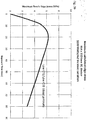
- FIG. 3a in which a solar absorbing low CTE/soda-lime glass laminate subject to 1000 W/m 2 incident radiation has a higher peak stress level compared to a soda-lime/soda-lime laminate structure under the same solar absorption conditions, also shown in FIG. 3a .
- maximum edge stress changes over time as the EC laminate absorbs more solar radiation, up to a maximum stress of about 20.5 MPa after approximately 40 minutes.
- heat conduction through the glass from the exposed region to the shadowed edge region will cause the temperature to equilibrate and corresponding thermal stresses to decrease from their peak level. It is believed that these stresses may be reduced when two low CTE panels are laminated together, such as shown in FIG. 3b , under the same edge frame shadow and solar absorption conditions as shown in FIG. 3a .
- the edge of EC substrate 31 is protected from handling and mechanical damage. Without wishing to be bound by any particular theory, it is believed that if the edges of EC substrate 31 are significantly nicked or chipped, the overall strength of the EC device could be compromised.
- the EC substrate 31 is indented relative to EC outer laminate glass pane 22.
- the size of the EC substrate 31 is slightly smaller than the size of the EC outer laminate glass pane 22, in at least one dimension, preferably in at least two dimensions, and more preferably in all dimensions.
- EC substrate 31 is indented about 0.5mm to about 3 mm in at least one dimension, and preferably about 0.5 mm to about 3 mm around the perimeter, with respect to glass pane 22. In other embodiments, EC substrate 31 is indented about 1 mm to about 2.0 mm, in at least one dimension, and preferably about 1 mm to about 2.0 mm around the perimeter with respect to glass pane 22.
- the depth of the indentation is determined by the automated placement tolerances of the two pieces of glass during the lamination layup/manufacturing process as well as any slight movements incurred during the thermal lamination process.
- the interlayer material is allowed to flow around the edge of EC substrate 31 providing an element of protection which, it is believed, further protects the EC device laminate 29 from damage during shipment and installation.
- excess interlayer material is added to achieve this.
- additional protective materials can be deposited around the perimeter of the.EC device such as polymers (including but not limited to epoxies, urethanes, silicones, and acrylates). These materials can be applied in varying amounts to achieve the desired outcome.
- the interlayer material may be selected from any material which allows for the EC device 32 to be laminated, by those methods known in the art, to the EC outer laminate glass pane 22.
- the interlayer material 28 should possess a combination of characteristics including: (a) high optical clarity; (b) low haze; (c) high impact resistance; (d) high penetration resistance; (e) ultraviolet light resistance; (f) good long term thermal stability; (g) sufficient adhesion to glass and/or other polymeric materials/sheets; (h) low moisture absorption; (i) high moisture resistance; (j) excellent weatherability; and (k) high stress load resistance (e.g. impact loading or windloading).
- the interlayer material 28 at least provides sufficient adhesion to both the EC device 32 and EC outer laminate glass pane 22 in order to prevent delamination during in-service stress loads and also be selected such that it does not negatively affect the visual characteristics of the EC device laminate 29.
- the interlayer material should be selected such that industry standard performance criteria is satisfied for both loading modes (see, for example, ANSI Z97.1 for impact testing and ASTM E1300 for windload criteria).
- a suitable interlayer material 28 is polyvinylbutyral (PVB), available from Solutia Inc, (St. Louis, Missouri) under the trade name SaflexTM. PVB is also available from DuPont (Wilmington, DE) under the trade name ButaciteTM.
- Other suitable materials for interlayer material 28 include ionomeric materials such as SentryGlas PlusTM (SGP) from DuPont, ethylenevinyl acetate (EVA) and cross-linking polyurethanes (e.g. cast-in-place resins) or thermoplastic polyurethanes. Of course, mixtures of any of the above identified materials may be used.
- interlayer material 28 can be used as an interlayer material 28 provided that they satisfy at least some of the thermomechanical, adhesion, and optical transparency functional requirements recited above.
- This also includes interlayer materials composed of composite polymer layers designed for improved sound attenuation, ballistic-resistant and blast-resistant applications. These materials are readily available to those of skill in the art.
- the interlayer material 28 may include silicones and epoxies.
- the EC substrate 31 and EC outer laminate glass pane 22 are comprised of the same material, it is believed that both glass panels would have about the same coefficient of thermal expansion. Where the materials differ, i.e . a mismatch situation such as in FIG. 2 , without wishing to be bound by any particular theory, it is believed that the selection of an appropriate interlayer material. 28 could affect the transfer or distribution of stress between the mismatched glass panels and therefore, it is believed, relieve at least some of the stresses present at various points in the laminate.
- the interlayer should be selected such that it either be (1) compliant enough not to transmit tensile stresses from the higher CTE glass panel to the lower CTE glass panel; or (2) stiff enough from the lamination temperature such that compressive stresses would be transmitted from the high CTE glass panel to the low CTE glass panel during cooling with negligible polymer mechanical relaxation at low temperatures.
- CTE coefficient of thermal expansion
- FIGs. 3a and 3b provide a comparison of peak edge tensile strength for a laminate (where the component panels in this case have thicknesses of 0.7 mm and 6 mm, respectively) exposed to solar irradiation, with the edges shadowed by a 1" window/architectural frame.
- Matched (low CTE/low CTE; soda-lime/soda-lime) and mismatched (low CTE/soda-lime) examples are shown as a function of time.
- the effective stress for the low CTE/soda-lime combination may be larger than for the soda-lime/soda-lime combination.
- the resulting edge stress may depend on the thermo mechanical properties of the interlayer material.
- the EC device laminates 29 (or IGUs 30 comprising these laminates) are believed to withstand stresses similar to those encountered by traditional electrochromic devices manufactured on tempered or heat-treated glass substrates (or IGUs comprising such traditional electrochromic devices).
- the EC device laminates 29 or IGUs 30 pass about the same industry standard tests as traditional electrochromic devices or IGUs. In other embodiments, by withstanding similar stresses it is meant that that the EC device laminates 29 or IGUs 30 can withstand (i) stresses safely in excess of maximum in-service thermomechanical stresses encountered in traditional EC applications, and/or (ii) at least about 50% of the same service loads or stresses as traditional electrochromic devices or IGUs. In some embodiments, the EC device laminate 29 is able to withstand a thermal edge stress (or service load) of at least about 17 MPa. In other embodiments, the EC device laminate is able to withstand a thermal edge stress of at least about 21 MPa.
- the EC device 29 or EC substrate has an edge strength of at least about 69 MPa. In yet other embodiments, the EC device or EC substrate has an edge strength of at least about 75 MPa. In even further embodiments, the EC device or EC substrate has an edge strength of at least about 100 MPa.
- the EC laminate 29 or EC substrate 31 is part of an IGU.
- the glass panel 20, which is used to form the IGU may be selected from any material, including glasses or plastics, traditionally used in IGU structures. For example, any kind of glass (soda-lime glass, low CTE glass, tempered glass, and/or annealed glass) or plastic may be used.
- the glass panel 20 may itself be a multipane laminate of one or more materials (multiple panes of glass multiple panes of plastic, alternating glass, plastic panes in any order).
- the glass panel 20 may also be tinted with any color or coated on one or both sides in any traditional manner, such as chemical or physical vapor deposition coating.
- the glass panel 20 may be an electrochromic or thermochromic device.
- the glass panel 20 may be laser cut or be mechanically scribed.
- IGU 30 of FIG. 1B may be a triple pane IGU, i.e . an IGU containing an additional glass (or polymer, e.g. acrylic) panel 20 adjacent to one of glass panel 20 or EC device laminate 29, but separated by spacers.
- Glass panel 20 may have any thickness or have any properties, provided it meets minimum commercial or residential building codes and/or window standards.
- an electrochromic device laminate comprising providing an electrochromic substrate; fabricating a plurality of electrochromic device precursors on the substrate; cutting each of the electrochromic device precursors into individual electrochromic devices, and laminating each of the individual electrochromic devices to a separate outer laminate glass pane.
- an "electrochromic device precursor” is an EC device, typically a stack of thin films as described above, applied or deposited on a substrate prior to the cutting of that substrate into individual EC devices.
- multiple EC device precursors are fabricated on any single substrate, or as described herein, substrate daughter pane.
- the EC precursor layout is designed to incorporate sufficient space between the precursors to allow for cutting, preferably without damaging any films or the stack in general.
- the EC device (or precursor) 32 is produced, in general, by coating or applying the EC stack 21 on a large substrate panel 31, such as annealed glass.
- the stack may be applied or deposited according to those methods known in the art and as incorporated herein.
- the EC device (or precursor) 32 is then subsequently cut by laser cutting to a desired dimension depending on the ultimate application.
- the panel may be cut into any size or shape.
- the substrate may also have been pre-cut from a larger panel.
- the device 32 is then laminated to an EC outer laminate glass pane 22, preferably to provide additional mechanical strength.
- the EC laminate 29 can be constructed with the EC device substrate 32 as shown in FIG. 1B (i.e.
- the EC laminate 29 can be constructed with the EC device substrate 32 oriented with the EC film stack 21 in contact with the interlayer material 28 (i.e. the EC film stack on the inside of the laminate).
- the EC device laminate 29 is processed, it is optionally combined with glass 20 to form an IGU 30.
- the EC outer laminate glass pane is about the same size as the EC device. In other embodiments, the EC outer laminate glass pane is a different size than the EC device. In some embodiments, the EC substrate is indented relative to the outer glass pane, as described above. As further detailed herein, the EC outer laminate glass may have about the same or different thicknesses and/or coefficients of thermal expansion as the EC device (or the substrate on which the EC device is deposited). The outer laminate glass pane may be mechanically cut or laser cut.
- Applicants have discovered a manufacturing approach which involves first cutting a large panel of an EC substrate into one or more substrate daughter panels, followed by applying the 'coat-then-cut' concept described above, such as to each of the one or more substrate daughter panels (this process is hereinafter referred to as a "cut-then-coat-then-cut" process).
- another aspect of the present invention is a process of manufacturing an electrochromic device laminate comprising providing an electrochromic substrate; cutting the electrochromic substrate into one or more substrate daughter panels; fabricating a plurality of electrochromic device precursors on each of the one or more substrate daughter panels; cutting each of the electrochromic device precursors into individual electrochromic devices; and laminating each of the individual electrochromic devices to a separate outer laminate glass pane.
- a large substrate panel of annealed glass is cut into one or more substrate daughter panels.
- a large substrate panel of annealed glass is cut into a plurality of substrate daughter panels.
- Each of the substrate daughter panels may be about the same size and/or shape, or may be different sizes and/or shapes.
- the initial large EC substrate may be cut into three equally sized substrate daughter panels or may be cut into three substrate daughter panels with each having a different size. At least some of the edges of the substrate daughter panels may then undergo an optional edge grinding process, followed preferably, by washing.
- the large substrate panel is cut into a single smaller (in at least one dimension) substrate daughter panel.
- the substrate daughter panels are loaded onto carriers for further processing, i.e. fabrication of the EC device precursors by coating each of the substrate daughter panels with an EC stack as described herein. Any number of substrate daughter panels may be loaded onto any single carrier, but it is preferred to optimize the surface area of the carrier with as many substrate daughter panels as will fit.
- Each of the EC device precursors on each of the substrate daughter panels are then further cut, such as by a laser cutting.
- the cut-then-coat-then-cut process provides several advantages.
- applying coatings e.g., EC stacks
- sputtering on smaller pieces of glass first cut from a larger substrate panel, could assist in alleviating any potential non-uniformity.
- the substrate glass is held vertically during coating. Without wishing to be bound by any particular theory, it is also believed that bowing could be caused by thermal stresses. It is believed that any thermal stresses could likewise be reduced by using substrate daughter panels, preferably smaller substrate daughter panels.
- certain desired substrate glass sizes are not always available from a manufacturer.
- glass from a manufacturer may be too large to fit in a carrier or in a reactive sputtering chamber.
- it may be more cost effective to buy larger pieces of glass and first cut them to fit into a carrier.
- edges of the as-received glass may not always be in a condition suitable for immediate processing. In these cases, it is desirable to first cut the glass into smaller daughter panels having a defect free edge or an edge that meets downstream manufacturing and processing requirements.
- any piece of large glass may contain a defect.
- a glass panel(s) without the defect can be cut from the large glass panel, without wasting large amounts of glass or processing time.
- lamination step in the "coat-then-cut” and the "cut-then-coat-then-cut” processes are carried out using methods known to those of skill in the art.
- typical lamination processes include heating the laminate under moderate pressures to create a partial bond between the glass panels, e.g. a nip roller process, followed by an extended bonding process, e. g . using an autoclave, at elevated temperatures and pressures to complete the bonding to the glass and either remove residual air or dissolve the air into the polymer structure to create an optically-clear interlayer.
- a laser is used to cut the EC device laminate 29 or the EC substrate 31.
- laser cut means (i) using a laser to.create a thin crack perpendicular to the substrate surface which is subsequently propagated through the glass by an applied bending moment to produce a complete separation, or (ii) a complete cut through the glass by a laser-induced crack that is propagated along the length of the substrate to complete separation.
- the process of laser cutting is equally applicable to the "coat-then-cut” and the "cut-then-coat-then-cut” processes.
- an electrochromic device laminate comprising providing an electrochromic substrate; fabricating a plurality of electrochromic device precursors on the substrate; laser cutting each of the electrochromic device precursors into individual electrochromic devices; and laminating each of the individual electrochromic devices to a separate outer laminate glass pane.
- the laser cutting process involves either inducing a thin surface crack later propagated to separation by application of a bending moment, or a complete "cut-through” by initiating and propagating a crack along the substrate to complete separation with no subsequent bending or "breakout" required.
- a thermally tough, innovative laminated outer glazing is fabricated using a focused laser beam to facilitate cutting of the coated glass substrates into individual daughter panes.
- the laser energy locally heats the glass followed by rapid cooling along the separation lines. This results in crack formation perpendicular to the glass resulting in an edge that is free of chips and additional microcracks that may cause contamination and edge weakening, respectively.
- the resultant laser processed edge does not require any additional edge finishing.
- the laser-cut edges can withstand stresses about 2 to about 3 times higher than standard mechanically cut edges and, it is believed, are of comparable edge strength to heat-strengthened glass. Consequently, it is believed that the laser cut, untempered EC device substrates can withstand temperature variations, and hence the stresses associated with such temperature variations, that are typically generated in the field when the glass is deeply tinted.
- the laser cut panels are able to withstand stresses of at least about 69 MPa. In yet other embodiment, the laser cut panels are able to withstand stresses of at least about 75 MPa. In yet other embodiment, the laser cut panels are able to withstand stresses of at least about 100 MPa. In even further embodiments, the laser cut panels are able to withstand stress of between about 70 MPa and about 310MPa.
- Impact testing was performed on "mismatched" laminates comprising: (1) an EC substrate 31, comprised of annealed soda-lime float glass or low-CTE glass; and (2) an EC outer laminate glass pane 22, comprised either of a heat strengthened glass, tempered glass, or annealed glass, as shown in FIG. 4 .
- the impact data suggest a useful design window with respect to EC substrate 31 and EC outer laminate glass pane 22 thicknesses.
- Polyvinylbutyral (PVB) and ionomer polymers (SGP from DuPont) were tested as interlayer materials 28.
- the SGP showed a narrower design window with respect to EC substrate/support substrate and interlayer thickness compared to PVB which, without wishing to be bound by any particular theory, it is believed better PVB performance is related to the enhanced compliance/stretching of the PVB material.
- FIG. 4 summarizes impact testing data as function of EC substrate 31, EC outer laminate glass pane 22, and interlayer 28 thickness.
- FIG. 4 demonstrates different combinations of EC substrate 31 thickness, EC outer laminate glass pane 22 thickness and interlayer material 28 thickness.
- the data suggested application over a wide range of glass and interlayer thicknesses. It is believed that PVB, is more robust with respect to glass and interlayer thicknesses.
- test standard for lamination glazing is issued by American National Standards Institute standard, ANTI Z97.1-2004 (American National Standard for Safety Glazing Materials Used in Buildings Safety Performance Specifications Method of Test). This standard establishes both the specifications and methods of testing for safety glazing materials as used for building and architectural purposes. The testing involves impact of a 100 pound bag of lead shot held at the end of a tether and swung into the centerline of a laminated glass panel.
- CPSC Consumer Products Safety Council
- the pass/fail criteria for the Z97.1 and 16CFR1201 tests are slightly different.
- the Z97.1 test allows breakage and formation of a tear/hole smaller than would allow a 3-inch diameter ball to pass through.
- the 16CFR1201 test additionally requires that a 3-inch ball weighing 4 pounds will not fall through the opening after 1 second duration when the panel is in a horizontal position.
- the pass/fail data reported are based on Z97.1 criteria, but the rigidity of the laminate would, we believe, allow for a 16CFR1201 pass.
- Example 1-EC Laminate Component Material Properties EC outer laminate glass pane Fully tempered soda-lime glass Thickness: 3.2mm CTE: 8.5ppm/K EC substrate Annealed soda-lime float glass Thickness: 1.7mm CTE: 8.5ppm/K Interlayer material PVB Thickness: 0.76mm
- Example 1 The laminated EC structure of Example 1 was manufactured according to a "cut-then-coat" process. The lamination was performed using a conventional nip roller/autoclave process. Equivalent results could be obtained using a vacuum laminating process.
- Example 2-EC Laminate Component Material Properties EC outer laminate glass pane Fully tempered soda-lime glass Thickness: 4mm CTE: 8.5ppm/K EC substrate Annealed soda-lime float glass Thickness: 1.7mm CTE: 8.5ppm/K Interlayer material PVB Thickness: 0.76mm
- the laminated EC structure of Example 2 was manufactured according to a "cut-then-coat" process.
- the lamination was performed using a conventional nip roller/autoclave process.
- the laminated EC structure having the components detailed above passed the ANSI 297.1 standard for impact testing.
- the laminated EC structure of Example 3 was manufactured according to a "cut-then-coat" process.
- the lamination was performed using a conventional nip roller/autoclave process.
- the laminated EC structure of Example 4 was manufactured according to a "cut-then-coat" process.
- the lamination was performed using a conventional nip roller/autoclave process.
- the laminated EC structure having the components detailed above passed the ANSI Z97.1 standard for impact testing.
- Example 5-EC Laminate Component Material Properties EC outer laminate glass pane Fully tempered soda-lime glass Thickness: 4mm CTE: 8.5ppm/K EC substrate Annealed borofloat CTE float glass Thickness: 1.7mm CTE: 3.3ppm/K Interlayer material PVB Thickness: 0.76mm
- the laminated EC structure of Example 5 was manufactured according to a "cut-then-coat" process.
- the lamination was performed using a conventional nip roller/autoclave process.
- Example 6-EC Laminate Component Material Properties EC outer laminate glass pane Heat-strengthened soda-lime float glass Thickness: 2.3mm CTE: 8.5ppm/K EC substrate Annealed soda-lime float glass Thickness: 1.7mm CTE: 8.5ppm/K Interlayer material SentryGlas Plus (DuPont) Thickness: 1.5mm
- the laminated EC structure of Example 6 was manufactured according to a "cut-then-coat" process.
- the lamination was performed using a conventional nip roller/autoclave process.
- Example 7-EC Laminate Component Material Properties EC outer laminate glass pane Heat-strengthened soda-lime float glass Thickness: 2.3mm CTE: 8.5ppm/K EC substrate Annealed soda-lime float glass Thickness: 1.7mm CTE: 8.5ppm/K Interlayer material PVB Thickness: 0.76mm
- Example 7 The laminated EC structure of Example 7 was manufactured according to a "cut-then-coat" process. The lamination was performed using a conventional nip roller/autoclave process.
- Example 8-SageGlass ® EC device Component Material Properties Interior Glass of IGU fully tempered soda-lime float glass Thickness: 6mm CTE: 8.5ppm/K EC substrate fully tempered soda-lime float glass Thickness: 6mm CTE: 8.5ppm/K
- the IGU of Example 8 was manufactured according to the standard manufacturing processes described herein.
- the IGU having the components detailed above passed the ANSI Z97.1 standard for impact testing.
- edge strength for a variety of glass compositions, substrate thicknesses and mechanical testing sample orientations.
- the best quantitative measurement of edge strength for laser cut glass has been performed using a four-point bend test setup.
- the four-point bend an example using a 'ying down' sample orientation shown in FIG. 5 , the entire region under the inner span is subjected to the same bending moment, and therefore, it is believed, allows for a larger effective area to be interrogated.
- edge strength in both 'edge-on' and 'lying down' orientations was initially used because it allows for testing of both top and bottom edges at the same time, in similar stress conditions as would be seen in service.
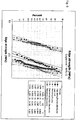
- FIG. 6 further shows a comparative probability plot of edge strength for mechanical and laser scribing. It is believed that the laser scribed panels show a strength of at least 69 MPa, preferably about 75 MPa, more preferably about 100 MPa.
- FIG. 6 also provides a comparison of experimental testing (mechanical (“Mechanical Scribe”) and ("Laser cut”) and literature data (adjusted for differences in test sample geometry).
- Experimental testing mechanical (“Mechanical Scribe") and ("Laser cut") and literature data (adjusted for differences in test sample geometry).
- Our test data for annealed samples made using conventional mechanical scribe and laser cut processes are shown as triangles and squares, respectively in FIG. 6 .
- the strength distribution of laser-cut glass (representing the total data from five different laser cutting campaigns using different laser cutting machines) can be described as having a performance between HS and FT performance.
- Example 9-Laser-cut Laminate Component Material Properties EC outer laminate glass pane Fully-tempered soda-lime float glass Thickness: 3.2mm CTE: 8.5ppm/K EC substrate Annealed soda-lime float glass Thickness: 1.7mm CTE: 8.5ppm/K Interlayer material PVB Thickness: 0.76mm
- the laser-cut laminate of Example 9 was manufactured according to a "coat-then-cut" process.
- the lamination was performed using a conventional nip roller/autoclave process.
- the EC substrate EC device or device precursor
- the laser-cut laminate edge strength was measured by inducing edge stresses by creation of a temperature gradient in the sample.
- the temperature gradient was created using a silicone heating pad that was smaller in laterial dimensions compared to the laminate.
- the pad was placed on the surface of the laminate with an unheated perimeter about 25mm wide.
- the magnitude of the gradient was controlled by adjusting the applied power to the heating pad (controlled by a variac variable power supply) while keeping the laminate edges near room temperature.
- the edge stresses created by the induced temperature gradient were directly measured using photoelastic techniques (Stress Photonics, Inc., Madison, WI).
- the laser-cut, laminated EC structures having the components detailed above had an edge strength of at least about 60 MPa after lamination.
- a process capability study of as-fabricated thermal laser scribe (TLS) processing was also performed.
- the study used the mechanical, four-point bend test described above. Data from over 80 samples from five testing sessions were collected. The data, representing five different TLS campaigns over a six-month period, were used to develop a process capability based on different maximum in-service edge stresses.
- the process capability Cpk suggested that the as-fabricated strength was sufficient to provide a low probability of failure in the operational stress environment for EC device laminate window applications.
Landscapes
- Physics & Mathematics (AREA)
- Nonlinear Science (AREA)
- Chemical & Material Sciences (AREA)
- Optics & Photonics (AREA)
- General Physics & Mathematics (AREA)
- Engineering & Computer Science (AREA)
- Materials Engineering (AREA)
- Organic Chemistry (AREA)
- Manufacturing & Machinery (AREA)
- Mathematical Physics (AREA)
- Crystallography & Structural Chemistry (AREA)
- Health & Medical Sciences (AREA)
- Toxicology (AREA)
- Thermal Sciences (AREA)
- Joining Of Glass To Other Materials (AREA)
- Electrochromic Elements, Electrophoresis, Or Variable Reflection Or Absorption Elements (AREA)
- Laminated Bodies (AREA)
- Re-Forming, After-Treatment, Cutting And Transporting Of Glass Products (AREA)
Priority Applications (1)
| Application Number | Priority Date | Filing Date | Title |
|---|---|---|---|
| EP17156934.6A EP3216597A1 (en) | 2010-03-05 | 2011-03-04 | Electrochromic device on glass substrate |
Applications Claiming Priority (3)
| Application Number | Priority Date | Filing Date | Title |
|---|---|---|---|
| US31100110P | 2010-03-05 | 2010-03-05 | |
| US41215310P | 2010-11-10 | 2010-11-10 | |
| EP11708645.4A EP2542407B2 (en) | 2010-03-05 | 2011-03-04 | Lamination of electrochromic device to glass substrates |
Related Parent Applications (3)
| Application Number | Title | Priority Date | Filing Date |
|---|---|---|---|
| EP11708645.4A Division EP2542407B2 (en) | 2010-03-05 | 2011-03-04 | Lamination of electrochromic device to glass substrates |
| EP11708645.4A Division-Into EP2542407B2 (en) | 2010-03-05 | 2011-03-04 | Lamination of electrochromic device to glass substrates |
| EP11708645.4 Division | 2011-03-04 |
Related Child Applications (1)
| Application Number | Title | Priority Date | Filing Date |
|---|---|---|---|
| EP17156934.6A Division EP3216597A1 (en) | 2010-03-05 | 2011-03-04 | Electrochromic device on glass substrate |
Publications (2)
| Publication Number | Publication Date |
|---|---|
| EP2641734A1 EP2641734A1 (en) | 2013-09-25 |
| EP2641734B1 true EP2641734B1 (en) | 2017-02-22 |
Family
ID=43983540
Family Applications (3)
| Application Number | Title | Priority Date | Filing Date |
|---|---|---|---|
| EP11708645.4A Active EP2542407B2 (en) | 2010-03-05 | 2011-03-04 | Lamination of electrochromic device to glass substrates |
| EP17156934.6A Pending EP3216597A1 (en) | 2010-03-05 | 2011-03-04 | Electrochromic device on glass substrate |
| EP13173248.9A Active EP2641734B1 (en) | 2010-03-05 | 2011-03-04 | Lamination of electrochromic device to glass substrates |
Family Applications Before (2)
| Application Number | Title | Priority Date | Filing Date |
|---|---|---|---|
| EP11708645.4A Active EP2542407B2 (en) | 2010-03-05 | 2011-03-04 | Lamination of electrochromic device to glass substrates |
| EP17156934.6A Pending EP3216597A1 (en) | 2010-03-05 | 2011-03-04 | Electrochromic device on glass substrate |
Country Status (8)
| Country | Link |
|---|---|
| US (6) | US8482837B2 (enExample) |
| EP (3) | EP2542407B2 (enExample) |
| JP (4) | JP5877166B2 (enExample) |
| KR (1) | KR20130010899A (enExample) |
| CN (2) | CN102883880B (enExample) |
| BR (1) | BR112012022488A2 (enExample) |
| ES (2) | ES2450520T5 (enExample) |
| WO (1) | WO2011109688A1 (enExample) |
Families Citing this family (102)
| Publication number | Priority date | Publication date | Assignee | Title |
|---|---|---|---|---|
| JPH0714312Y2 (ja) | 1990-10-10 | 1995-04-05 | 新日本製鐵株式会社 | 鋼管用吊具 |
| US9782949B2 (en) | 2008-05-30 | 2017-10-10 | Corning Incorporated | Glass laminated articles and layered articles |
| US8514476B2 (en) | 2008-06-25 | 2013-08-20 | View, Inc. | Multi-pane dynamic window and method for making same |
| US20210063836A1 (en) | 2017-04-26 | 2021-03-04 | View, Inc. | Building network |
| US11314139B2 (en) | 2009-12-22 | 2022-04-26 | View, Inc. | Self-contained EC IGU |
| US10303035B2 (en) | 2009-12-22 | 2019-05-28 | View, Inc. | Self-contained EC IGU |
| CN102883880B (zh) | 2010-03-05 | 2017-02-08 | Sage电致变色显示有限公司 | 电致变色装置到玻璃衬底的层合 |
| FR2962682B1 (fr) | 2010-07-16 | 2015-02-27 | Saint Gobain | Vitrage electrochimique a proprietes optiques et/ou energetiques electrocommandables |
| US8270059B2 (en) | 2010-08-05 | 2012-09-18 | Soladigm, Inc. | Multi-pane electrochromic windows |
| US12496809B2 (en) * | 2010-11-08 | 2025-12-16 | View Operating Corporation | Electrochromic window fabrication methods |
| US9958750B2 (en) | 2010-11-08 | 2018-05-01 | View, Inc. | Electrochromic window fabrication methods |
| US8164818B2 (en) | 2010-11-08 | 2012-04-24 | Soladigm, Inc. | Electrochromic window fabrication methods |
| US9442339B2 (en) | 2010-12-08 | 2016-09-13 | View, Inc. | Spacers and connectors for insulated glass units |
| EP3444664A1 (en) * | 2010-12-08 | 2019-02-20 | View, Inc. | Improved spacers for insulated glass units |
| US8643933B2 (en) | 2011-12-14 | 2014-02-04 | View, Inc. | Connectors for smart windows |
| US10180606B2 (en) | 2010-12-08 | 2019-01-15 | View, Inc. | Connectors for smart windows |
| US11054792B2 (en) | 2012-04-13 | 2021-07-06 | View, Inc. | Monitoring sites containing switchable optical devices and controllers |
| US9454055B2 (en) | 2011-03-16 | 2016-09-27 | View, Inc. | Multipurpose controller for multistate windows |
| US10989977B2 (en) | 2011-03-16 | 2021-04-27 | View, Inc. | Onboard controller for multistate windows |
| US10175549B2 (en) | 2011-03-16 | 2019-01-08 | View, Inc. | Connectors for smart windows |
| US10429712B2 (en) | 2012-04-20 | 2019-10-01 | View, Inc. | Angled bus bar |
| US9795849B2 (en) | 2011-06-01 | 2017-10-24 | Triad Sports, Inc. | Ball net structure with alterable base |
| US9885934B2 (en) | 2011-09-14 | 2018-02-06 | View, Inc. | Portable defect mitigators for electrochromic windows |
| US12061402B2 (en) | 2011-12-12 | 2024-08-13 | View, Inc. | Narrow pre-deposition laser deletion |
| US12403676B2 (en) | 2011-12-12 | 2025-09-02 | View Operating Corporation | Thin-film devices and fabrication |
| US11865632B2 (en) | 2011-12-12 | 2024-01-09 | View, Inc. | Thin-film devices and fabrication |
| US10739658B2 (en) | 2011-12-12 | 2020-08-11 | View, Inc. | Electrochromic laminates |
| US10606142B2 (en) | 2011-12-12 | 2020-03-31 | View, Inc. | Thin-film devices and fabrication |
| US12321075B2 (en) | 2011-12-12 | 2025-06-03 | View Operating Corporation | Electrochromic laminates |
| US11048137B2 (en) * | 2011-12-12 | 2021-06-29 | View, Inc. | Thin-film devices and fabrication |
| US11719039B2 (en) | 2011-12-14 | 2023-08-08 | View, Inc. | Connectors for smart windows |
| US9281672B2 (en) | 2012-01-20 | 2016-03-08 | Sage Electrochromics, Inc. | Electrical connectivity within architectural glazing frame systems |
| US20130222878A1 (en) | 2012-02-28 | 2013-08-29 | Sage Electrochromics, Inc. | Multi-zone electrochromic devices |
| US20130222877A1 (en) | 2012-02-28 | 2013-08-29 | Sage Electrochromics, Inc. | Multi-zone electrochromic devices |
| US9341912B2 (en) | 2012-03-13 | 2016-05-17 | View, Inc. | Multi-zone EC windows |
| US12153320B2 (en) | 2012-03-13 | 2024-11-26 | View, Inc. | Multi-zone EC windows |
| US12429742B2 (en) | 2012-03-13 | 2025-09-30 | View Operating Corporation | Methods of controlling multi-zone tintable windows |
| US9638977B2 (en) | 2012-03-13 | 2017-05-02 | View, Inc. | Pinhole mitigation for optical devices |
| US11635666B2 (en) | 2012-03-13 | 2023-04-25 | View, Inc | Methods of controlling multi-zone tintable windows |
| US20130258436A1 (en) | 2012-04-03 | 2013-10-03 | Sage Electrochromics, Inc. | Patterned obscuration lines for electrochromic devices |
| IN2014DN08858A (enExample) * | 2012-04-05 | 2015-05-22 | Sage Electrochromics Inc | |
| US11255120B2 (en) | 2012-05-25 | 2022-02-22 | View, Inc. | Tester and electrical connectors for insulated glass units |
| US20140000191A1 (en) | 2012-06-27 | 2014-01-02 | Sage Electrochromics, Inc. | Shoulder spacer key for insulated glazing units |
| US10288971B2 (en) | 2012-08-23 | 2019-05-14 | View, Inc. | Photonic-powered EC devices |
| US9146437B2 (en) | 2013-01-31 | 2015-09-29 | Gentex Corporation | Electro-optic window assembly |
| EP2965149B1 (en) | 2013-03-08 | 2023-06-28 | Sage Electrochromics, Inc. | Electrochromic device with multiple independently controllable zones and internal busbars |
| EP2969375B1 (en) * | 2013-03-15 | 2018-09-12 | Kinestral Technologies, Inc. | Laser cutting strengthened glass |
| EP2781296B1 (de) | 2013-03-21 | 2020-10-21 | Corning Laser Technologies GmbH | Vorrichtung und verfahren zum ausschneiden von konturen aus flächigen substraten mittels laser |
| TWI685706B (zh) | 2013-06-18 | 2020-02-21 | 唯景公司 | 非矩形之電致變色裝置 |
| FR3012072B1 (fr) * | 2013-10-23 | 2021-01-01 | Saint Gobain | Verre feuillete mince pour pare-brise |
| FR3012071B1 (fr) * | 2013-10-23 | 2021-01-01 | Saint Gobain | Verre feuillete mince |
| US11556039B2 (en) * | 2013-12-17 | 2023-01-17 | Corning Incorporated | Electrochromic coated glass articles and methods for laser processing the same |
| TWI691772B (zh) | 2014-01-02 | 2020-04-21 | 美商唯景公司 | 薄膜裝置及其製造 |
| EP3572229B1 (en) | 2014-02-07 | 2021-10-27 | Corning Incorporated | Method of forming laminated glass structures |
| EP4145379A1 (en) | 2014-03-05 | 2023-03-08 | View, Inc. | Monitoring sites containing switchable optical devices and controllers |
| US11868103B2 (en) | 2014-03-05 | 2024-01-09 | View, Inc. | Site monitoring system |
| CN106458688A (zh) | 2014-03-31 | 2017-02-22 | 康宁股份有限公司 | 形成层压玻璃结构的机械加工方法 |
| EP3161956B1 (en) | 2014-06-25 | 2022-10-26 | Sage Electrochromics, Inc. | Solar powered device with scalable size and power capacity |
| EP3161552B1 (en) | 2014-06-30 | 2020-01-15 | View, Inc. | Control methods and systems for networks of optically switchable windows during reduced power availability |
| EP3166895B1 (en) | 2014-07-08 | 2021-11-24 | Corning Incorporated | Methods and apparatuses for laser processing materials |
| TWI659793B (zh) | 2014-07-14 | 2019-05-21 | 美商康寧公司 | 用於使用可調整雷射束焦線來處理透明材料的系統及方法 |
| US11740948B2 (en) | 2014-12-08 | 2023-08-29 | View, Inc. | Multiple interacting systems at a site |
| US10975612B2 (en) | 2014-12-15 | 2021-04-13 | View, Inc. | Seals for electrochromic windows |
| US10666189B2 (en) | 2015-01-06 | 2020-05-26 | Sage Electrochromics, Inc. | Set of window assemblies and a method of fabricating the same |
| US9874721B2 (en) | 2015-02-09 | 2018-01-23 | Apple Inc. | Camera lens system |
| US9817213B2 (en) * | 2015-04-23 | 2017-11-14 | Apple Inc. | Camera lens system with five lens components |
| US10274700B2 (en) | 2015-05-21 | 2019-04-30 | Apple Inc. | Camera lens system |
| WO2017019967A1 (en) | 2015-07-29 | 2017-02-02 | Sage Electrochromics, Inc. | Laminate including panels and a fill material between the panels and a process of forming the laminate |
| WO2017027407A1 (en) * | 2015-08-07 | 2017-02-16 | Kinestral Technologies, Inc. | Electrochromic device assemblies |
| US12366111B2 (en) | 2015-09-18 | 2025-07-22 | View Operating Corporation | Trunk line window controllers |
| JP6755944B2 (ja) * | 2015-10-07 | 2020-09-16 | ジェンテックス コーポレイション | 電気光学素子を組み込んだサンルーフ |
| WO2017116907A1 (en) * | 2015-12-29 | 2017-07-06 | Corning Incorporated | Asymmetric processing method for reducing bow in laminate structures |
| EP3470383A4 (en) | 2016-06-08 | 2020-02-19 | Agc Inc. | LIGHT GRADATOR AND DOUBLE GLASS LAMINATE |
| GB201614208D0 (en) * | 2016-08-19 | 2016-10-05 | Pilkington Group Ltd | Switchable glazing unit |
| CN110167891A (zh) | 2016-10-24 | 2019-08-23 | 康宁股份有限公司 | 用于对片状玻璃基材进行基于激光的机械加工的基材处理工位 |
| WO2018092520A1 (ja) * | 2016-11-18 | 2018-05-24 | 旭硝子株式会社 | 曲面板の加工装置、および外周部が加工された曲面板の製造方法 |
| CN110088676A (zh) | 2016-12-22 | 2019-08-02 | Sage电致变色显示有限公司 | 包括构造为保持连续渐变透射状态的电致变色器件的装置 |
| US11320713B2 (en) | 2017-02-16 | 2022-05-03 | View, Inc. | Solar power dynamic glass for heating and cooling buildings |
| JP2020513118A (ja) | 2017-04-12 | 2020-04-30 | サン−ゴバン グラス フランス | エレクトロクロミック構造およびエレクトロクロミック構造の分離方法 |
| JP7369924B2 (ja) | 2017-04-20 | 2023-10-27 | カーディナル アイジー カンパニー | 高性能プライバシーガラス構造 |
| US12147142B2 (en) | 2017-04-26 | 2024-11-19 | View, Inc. | Remote management of a facility |
| WO2019014613A1 (en) | 2017-07-13 | 2019-01-17 | Cardinal Ig Company | ELECTRICAL CONNECTION CONFIGURATIONS OF OPAQUE GLAZING STRUCTURES |
| US11360364B2 (en) | 2017-11-06 | 2022-06-14 | Cardinal Ig Company | Privacy glazing system with discrete electrical driver |
| CN108345133A (zh) * | 2017-12-13 | 2018-07-31 | 安徽国隆玻璃科技有限公司 | 一种电控调光夹胶玻璃及其制造工艺 |
| CN111566060B (zh) * | 2017-12-21 | 2022-11-08 | 康宁股份有限公司 | 包括低cte玻璃层的多层绝热玻璃单元 |
| EP3790735A1 (en) | 2018-05-09 | 2021-03-17 | Cardinal Ig Company | Electrically controllable privacy glazing with energy recapturing driver |
| CN108873536B (zh) * | 2018-06-01 | 2022-01-18 | Oppo广东移动通信有限公司 | 壳体及其制备方法、电子设备 |
| KR102742290B1 (ko) * | 2018-07-30 | 2024-12-12 | 코닝 인코포레이티드 | 단열 창 유닛 |
| EP4234229B1 (en) | 2018-08-17 | 2025-08-06 | Cardinal Ig Company | Privacy glazing structure |
| US11474385B1 (en) | 2018-12-02 | 2022-10-18 | Cardinal Ig Company | Electrically controllable privacy glazing with ultralow power consumption comprising a liquid crystal material having a light transmittance that varies in response to application of an electric field |
| EP3921152A1 (en) | 2019-02-08 | 2021-12-15 | Cardinal Ig Company | Low power driver for privacy glazing |
| WO2020223281A1 (en) | 2019-04-29 | 2020-11-05 | Cardinal Ig Company | Leakage current detection and control for one or more electrically controllable privacy glazing structures |
| WO2020223297A1 (en) | 2019-04-29 | 2020-11-05 | Cardinal Ig Company | Systems and methods for operating one or more electrically controllable privacy glazing structures |
| WO2020223277A1 (en) | 2019-04-29 | 2020-11-05 | Cardinal Ig Company | Staggered driving electrical control of a plurality of electrically controllable privacy glazing structures |
| KR20250159057A (ko) | 2019-05-09 | 2025-11-07 | 뷰 오퍼레이팅 코포레이션 | 건물의 제어 커버리지용 안테나 시스템 |
| US11631493B2 (en) | 2020-05-27 | 2023-04-18 | View Operating Corporation | Systems and methods for managing building wellness |
| CA3154442A1 (en) * | 2019-10-21 | 2021-04-29 | Thomas Bertin-Mourot | Fenestration assemblies and related methods |
| CN114846394A (zh) * | 2019-11-27 | 2022-08-02 | 康宁公司 | 用于在液晶面板中均匀传输的系统与方法 |
| CN115038583A (zh) * | 2019-12-18 | 2022-09-09 | 康宁公司 | 多板玻璃单元和用于制造多板玻璃单元的方法 |
| TW202206925A (zh) | 2020-03-26 | 2022-02-16 | 美商視野公司 | 多用戶端網路中之存取及傳訊 |
| CN113791510A (zh) * | 2021-08-06 | 2021-12-14 | 河北光兴半导体技术有限公司 | 用于电致变色玻璃的制备系统 |
| US20250044658A1 (en) * | 2021-12-06 | 2025-02-06 | Miru Smart Technologies Corp. | Method of manufacturing curved electrochromic devices |
Citations (1)
| Publication number | Priority date | Publication date | Assignee | Title |
|---|---|---|---|---|
| US20070090100A1 (en) * | 2004-04-27 | 2007-04-26 | Toshifumi Yonai | Glass cutting method and apparatus therefor |
Family Cites Families (107)
| Publication number | Priority date | Publication date | Assignee | Title |
|---|---|---|---|---|
| US3865294A (en) | 1972-04-10 | 1975-02-11 | Ppg Industries Inc | Subsurface cracks |
| IT980876B (it) | 1972-04-10 | 1974-10-10 | Ppg Industries Inc | Procedimento e dispositivo per il taglio del vetro in lastra |
| JPS57158623A (en) | 1981-03-27 | 1982-09-30 | Hitachi Ltd | Electrochromic display device |
| US4419386A (en) | 1981-09-14 | 1983-12-06 | Gordon Roy G | Non-iridescent glass structures |
| JPS609769Y2 (ja) | 1981-12-17 | 1985-04-05 | 旭硝子株式会社 | 強化調光体 |
| JPS59195629A (ja) | 1983-04-21 | 1984-11-06 | Toppan Printing Co Ltd | エレクトロクロミツク表示体 |
| FR2601150B1 (fr) | 1986-07-04 | 1991-05-31 | Saint Gobain Vitrage | Vitrage a transmission variable du type electrochrome |
| US5239406A (en) | 1988-02-12 | 1993-08-24 | Donnelly Corporation | Near-infrared reflecting, ultraviolet protected, safety protected, electrochromic vehicular glazing |
| JPH0818855B2 (ja) | 1988-12-21 | 1996-02-28 | 旭硝子株式会社 | 積層体 |
| FR2642890B1 (fr) | 1989-02-09 | 1991-04-12 | Saint Gobain Vitrage | Materiau colloide conducteur de cations alcalins et applications a titre d'electrolytes |
| EP0397237B1 (en) | 1989-05-08 | 1994-05-18 | Koninklijke Philips Electronics N.V. | Method of cleaving a plate of brittle material |
| FR2649691B1 (fr) * | 1989-07-11 | 1992-10-30 | Saint Gobain Vitrage Int | Vitrage electrochrome |
| US5124832A (en) | 1989-09-29 | 1992-06-23 | Ppg Industries, Inc. | Laminated and sealed electrochromic window |
| FR2666805B1 (fr) | 1990-09-14 | 1992-10-30 | Saint Gobain Vitrage Int | Procede d'obtention de vitrages electrochromes. vitrages electrochromes. |
| FR2677800B1 (fr) | 1991-06-14 | 1993-08-20 | Saint Gobain Vitrage Int | Materiau solide conducteur ionique, a partir d'un polymere et d'un sel de cation alcalin, application comme electrolyte. |
| US5248545A (en) | 1991-06-24 | 1993-09-28 | Ford Motor Company | Anti-iridescent coatings with gradient refractive index |
| US5724177A (en) | 1991-09-04 | 1998-03-03 | Sun Active Glass Electrochromics, Inc. | Electrochromic devices and methods |
| US5321544A (en) | 1991-09-04 | 1994-06-14 | Sun Active Glass Electrochromics, Inc. | Electrochromic structures and methods |
| EP0532408A1 (fr) | 1991-09-13 | 1993-03-17 | Saint-Gobain Vitrage International | Polymère conducteur protonique, application en tant qu'électrolyte dans des dispositifs électrochimiques |
| US5370775A (en) | 1992-04-10 | 1994-12-06 | Sun Active Glass Electrochromics, Inc. | Formation of chemically reduced electrode layers |
| US5404244A (en) | 1992-04-10 | 1995-04-04 | Sun Active Glass Electrochromics, Inc. | Electrochromic structures and methods |
| RU2117971C1 (ru) | 1992-04-10 | 1998-08-20 | Сан Эктив Гласс Электрокромикс, Инк. | Электрохромное устройство (варианты) и способ его изготовления (варианты) |
| FR2691550B1 (fr) | 1992-05-21 | 1995-04-21 | Saint Gobain Vitrage Int | Vitrage électrochrome architectural. |
| EP1004649A3 (en) | 1993-02-26 | 2000-07-26 | Donnelly Corporation | Electrochromic polymeric solid films, manufacturing electrochromic devices using such solid films, and processes for making such solid films and devices |
| JPH06300992A (ja) * | 1993-04-12 | 1994-10-28 | Nikon Corp | 度付きエレクトロクロミック眼鏡レンズの製造方法 及びそのレンズ |
| DE4345409C2 (de) | 1993-11-23 | 1998-03-05 | Johannes Luebbering Ag | Mobiles Präzisions-Bohrgerät |
| FR2716457B1 (fr) | 1994-02-23 | 1996-05-24 | Saint Gobain Vitrage Int | Matériau électrolyte conducteur protonique. |
| US5668663A (en) * | 1994-05-05 | 1997-09-16 | Donnelly Corporation | Electrochromic mirrors and devices |
| FR2719915B1 (fr) * | 1994-05-16 | 1996-06-14 | Saint Gobain Vitrage | Système électrochrome et son procédé d'alimentation. |
| JPH07318877A (ja) * | 1994-05-19 | 1995-12-08 | Hitachi Ltd | 液晶表示基板の製造方法 |
| US5530581A (en) * | 1995-05-31 | 1996-06-25 | Eic Laboratories, Inc. | Protective overlayer material and electro-optical coating using same |
| AUPN718195A0 (en) | 1995-12-18 | 1996-01-18 | Sola International Holdings Ltd | Laminate wafers |
| US5825526A (en) | 1996-04-24 | 1998-10-20 | Minnesota Mining And Manufacturing Company | Tape for use in manufacturing electrochromic devices |
| FR2752570B1 (fr) | 1996-08-22 | 1998-10-02 | Saint Gobain Vitrage | Vitrage a proprietes optiques et/ou energetiques variables |
| FR2753545B1 (fr) | 1996-09-18 | 1998-10-16 | Saint Gobain Vitrage | Dispositif electrochimique |
| US5724175A (en) | 1997-01-02 | 1998-03-03 | Optical Coating Laboratory, Inc. | Electrochromic device manufacturing process |
| US5995271A (en) | 1997-10-07 | 1999-11-30 | Optical Coating Laboratory, Inc. | Protective coating materials for electrochromic devices |
| DE19804314A1 (de) | 1998-02-04 | 1999-08-12 | Bayer Ag | Elektrochromes Display |
| JPH11240730A (ja) | 1998-02-27 | 1999-09-07 | Nec Kansai Ltd | 脆性材料の割断方法 |
| FR2781062B1 (fr) | 1998-07-09 | 2002-07-12 | Saint Gobain Vitrage | Vitrage a proprietes optiques et/ou energetiques electrocommandables |
| FR2781084B1 (fr) * | 1998-07-10 | 2007-08-31 | Saint Gobain Vitrage | Procede de traitement d'un dispositif electrochimique |
| US6407360B1 (en) | 1998-08-26 | 2002-06-18 | Samsung Electronics, Co., Ltd. | Laser cutting apparatus and method |
| DE19840186C2 (de) | 1998-09-03 | 2003-03-13 | Daimler Chrysler Ag | Verbundglasscheibe mit elektrisch steuerbarem Reflexionsgrad |
| US6157480A (en) * | 1998-09-21 | 2000-12-05 | Gentex Corporation | Seal for electrochromic devices |
| US6252197B1 (en) | 1998-12-01 | 2001-06-26 | Accudyne Display And Semiconductor Systems, Inc. | Method and apparatus for separating non-metallic substrates utilizing a supplemental mechanical force applicator |
| US6355125B1 (en) * | 1999-03-26 | 2002-03-12 | Agfa-Gevaert | Method for making an electric or electronic module comprising a glass laminate |
| JP2000290031A (ja) * | 1999-04-02 | 2000-10-17 | Nippon Sheet Glass Co Ltd | チャンネル状ガラスの切断方法及び切断装置 |
| DE19918936A1 (de) | 1999-04-27 | 2000-11-02 | Schott Glas | Verfahren und Vorrichtung zur Herstellung von Einzelglasscheiben |
| US6795226B2 (en) | 2000-05-04 | 2004-09-21 | Schott Corporation | Chromogenic glazing |
| US6643050B2 (en) | 2000-06-13 | 2003-11-04 | Ppg Industries Ohio, Inc. | Colored electrochromic transparent window assemblies |
| FR2811778B1 (fr) | 2000-07-13 | 2003-06-20 | Saint Gobain | Dispositif electrochimique du type electrochrome ou dispositif photovoltaique et ses moyens de connexion electrique |
| EP1305162A1 (en) * | 2000-07-20 | 2003-05-02 | Glaverbel | Glazing |
| FR2815374B1 (fr) | 2000-10-18 | 2003-06-06 | Saint Gobain | Vitrage feuillete et ses moyens d'etancheification peripherique |
| US7255451B2 (en) | 2002-09-20 | 2007-08-14 | Donnelly Corporation | Electro-optic mirror cell |
| US6587250B2 (en) | 2001-03-07 | 2003-07-01 | Acreo Ab | Electrochromic device |
| JP2002289899A (ja) * | 2001-03-23 | 2002-10-04 | Mitsubishi Heavy Ind Ltd | 太陽電池パネルの切断装置及び方法 |
| US6639708B2 (en) | 2001-04-24 | 2003-10-28 | Schott North America, Inc | Electrochromic safety glazing |
| KR100676249B1 (ko) | 2001-05-23 | 2007-01-30 | 삼성전자주식회사 | 기판 절단용 냉매, 이를 이용한 기판 절단 방법 및 이를수행하기 위한 장치 |
| FR2829723B1 (fr) | 2001-09-14 | 2004-02-20 | Saint Gobain | Vitrage de securite fonctionnalise |
| EP1441385A4 (en) * | 2001-10-31 | 2009-11-18 | Mitsuboshi Diamond Ind Co Ltd | METHOD FOR FORMING A CROP LINE ON A SEMICONDUCTOR WAFER AND A CROWDING DEVICE |
| JP2003197103A (ja) | 2001-12-27 | 2003-07-11 | Toshiba Corp | 平面型表示装置の製造方法 |
| US7832177B2 (en) * | 2002-03-22 | 2010-11-16 | Electronics Packaging Solutions, Inc. | Insulated glazing units |
| JP4370611B2 (ja) * | 2002-04-17 | 2009-11-25 | 日本電気硝子株式会社 | 平面表示装置用板ガラス |
| FR2840078B1 (fr) | 2002-05-22 | 2004-08-13 | Saint Gobain | Dispositif electrocommandable a proprietes optiques et/ou energetiques variables |
| DE10223512A1 (de) | 2002-05-27 | 2003-12-11 | Inst Neue Mat Gemein Gmbh | Laserstrukturierung von elektrooptischen Systemen |
| JP4032857B2 (ja) | 2002-07-24 | 2008-01-16 | ソニー株式会社 | タッチパネル用のガラス基板、タッチパネル及び携帯端末 |
| TWI300157B (en) * | 2002-09-10 | 2008-08-21 | Sipix Imaging Inc | Electrochromic or electrodeposition display and process for their preparation |
| JP2004148438A (ja) | 2002-10-30 | 2004-05-27 | Shibuya Kogyo Co Ltd | 脆性材料の割断方法およびその装置 |
| JP4105537B2 (ja) | 2002-12-24 | 2008-06-25 | 株式会社村上開明堂 | エレクトロクロミック素子 |
| TW200510152A (en) | 2003-01-10 | 2005-03-16 | Mitsuboshi Diamond Ind Co Ltd | Brittle material subscribing device and scribing method and automatic analysis line |
| US7300166B2 (en) * | 2003-03-05 | 2007-11-27 | Electrochromix, Inc. | Electrochromic mirrors and other electrooptic devices |
| JP2005037709A (ja) | 2003-07-15 | 2005-02-10 | Mitsubishi Electric Corp | 反射鏡およびその製造方法 |
| FR2857617B1 (fr) | 2003-07-16 | 2006-10-27 | Saint Gobain | Vitrage de securite fonctionnalise |
| AU2004294430B2 (en) | 2003-12-05 | 2010-04-01 | Asahi Glass Company, Limited | Method and device for cutting plate glass |
| DE102004014277A1 (de) | 2004-03-22 | 2005-10-20 | Fraunhofer Ges Forschung | Verfahren zum laserthermischen Trennen von Flachgläsern |
| US7835059B2 (en) * | 2004-05-21 | 2010-11-16 | Gentex Corporation | Tristate electrochromic device |
| US7855821B2 (en) * | 2004-11-15 | 2010-12-21 | Gentex Corporation | Electrochromic compounds and associated media and devices |
| US7372610B2 (en) | 2005-02-23 | 2008-05-13 | Sage Electrochromics, Inc. | Electrochromic devices and methods |
| JP2006256922A (ja) * | 2005-03-18 | 2006-09-28 | Central Glass Co Ltd | ガラス基板のアニール装置及びアニール方法 |
| US7586664B2 (en) | 2005-07-01 | 2009-09-08 | Ppg Industries Ohio, Inc. | Transparent electrode for an electrochromic switchable cell |
| US7593154B2 (en) | 2005-10-11 | 2009-09-22 | Sage Electrochromics, Inc. | Electrochromic devices having improved ion conducting layers |
| ATE496318T1 (de) * | 2006-07-28 | 2011-02-15 | Chromogenics Sweden Ab | Herstellung von gewölbten elektrochromen anordnungen |
| EP2049944B1 (en) | 2006-07-28 | 2011-06-15 | ChromoGenics AB | Manufacturing of electrochromic devices |
| DE102006042538B4 (de) * | 2006-09-11 | 2011-07-14 | FuTech GmbH, 39124 | Verbundglas, Verglasungselement und Verfahren zu deren Herstellung, und Verwendung des Verbundglases |
| US8017220B2 (en) | 2006-10-04 | 2011-09-13 | Corning Incorporated | Electronic device and method of making |
| JP5139739B2 (ja) * | 2007-07-19 | 2013-02-06 | パナソニック株式会社 | 積層体の割断方法 |
| US8102586B2 (en) | 2007-07-23 | 2012-01-24 | Kuwait University | Electronic window shading system for houses, transport vehicles and the like |
| US7884994B2 (en) * | 2007-10-16 | 2011-02-08 | Saint Gobain Glass France | Electrochromic layers, device and process of producing same |
| CN101925456B (zh) * | 2008-01-25 | 2013-10-16 | 旭硝子株式会社 | 玻璃树脂复合体的制造方法 |
| CN101497493B (zh) | 2008-02-01 | 2012-12-26 | 鸿富锦精密工业(深圳)有限公司 | 激光切割装置 |
| WO2009128334A1 (ja) | 2008-04-14 | 2009-10-22 | 三星ダイヤモンド工業株式会社 | 脆性材料基板の加工方法 |
| US9782949B2 (en) | 2008-05-30 | 2017-10-10 | Corning Incorporated | Glass laminated articles and layered articles |
| JP2009294461A (ja) | 2008-06-05 | 2009-12-17 | Toshiba Mobile Display Co Ltd | 液晶表示装置及びその製造方法 |
| US8051679B2 (en) | 2008-09-29 | 2011-11-08 | Corning Incorporated | Laser separation of glass sheets |
| JP5332510B2 (ja) | 2008-10-29 | 2013-11-06 | コニカミノルタ株式会社 | 透明導電性基板、及び電気化学表示素子 |
| JP5501602B2 (ja) * | 2008-11-13 | 2014-05-28 | 株式会社船井電機新応用技術研究所 | 表示装置 |
| EP2161490B1 (en) | 2008-11-30 | 2012-04-18 | Samsung Electronics Co., Ltd. | Supporting device to display apparatus |
| US7710671B1 (en) * | 2008-12-12 | 2010-05-04 | Applied Materials, Inc. | Laminated electrically tintable windows |
| US8347651B2 (en) | 2009-02-19 | 2013-01-08 | Corning Incorporated | Method of separating strengthened glass |
| JP2010194550A (ja) | 2009-02-23 | 2010-09-09 | Panasonic Corp | 脆性材料の割断方法および当該方法を用いたフラットパネルディスプレイの製造方法 |
| US20100279067A1 (en) * | 2009-04-30 | 2010-11-04 | Robert Sabia | Glass sheet having enhanced edge strength |
| US8289610B2 (en) * | 2009-08-27 | 2012-10-16 | Guardian Industries Corp. | Electrochromic devices, assemblies incorporating electrochromic devices, and/or methods of making the same |
| US8932510B2 (en) | 2009-08-28 | 2015-01-13 | Corning Incorporated | Methods for laser cutting glass substrates |
| CN102883880B (zh) * | 2010-03-05 | 2017-02-08 | Sage电致变色显示有限公司 | 电致变色装置到玻璃衬底的层合 |
| FR2962682B1 (fr) | 2010-07-16 | 2015-02-27 | Saint Gobain | Vitrage electrochimique a proprietes optiques et/ou energetiques electrocommandables |
| US8720228B2 (en) | 2010-08-31 | 2014-05-13 | Corning Incorporated | Methods of separating strengthened glass substrates |
| IN2014DN08858A (enExample) | 2012-04-05 | 2015-05-22 | Sage Electrochromics Inc |
-
2011
- 2011-03-04 CN CN201180013326.2A patent/CN102883880B/zh active Active
- 2011-03-04 ES ES11708645.4T patent/ES2450520T5/es active Active
- 2011-03-04 EP EP11708645.4A patent/EP2542407B2/en active Active
- 2011-03-04 WO PCT/US2011/027148 patent/WO2011109688A1/en not_active Ceased
- 2011-03-04 CN CN201611217082.0A patent/CN106932995B/zh active Active
- 2011-03-04 JP JP2012556257A patent/JP5877166B2/ja not_active Expired - Fee Related
- 2011-03-04 BR BR112012022488A patent/BR112012022488A2/pt not_active IP Right Cessation
- 2011-03-04 EP EP17156934.6A patent/EP3216597A1/en active Pending
- 2011-03-04 US US13/040,787 patent/US8482837B2/en active Active
- 2011-03-04 EP EP13173248.9A patent/EP2641734B1/en active Active
- 2011-03-04 KR KR1020127026169A patent/KR20130010899A/ko not_active Withdrawn
- 2011-03-04 ES ES13173248.9T patent/ES2621758T3/es active Active
- 2011-07-07 US US13/178,065 patent/US8482838B2/en active Active
-
2013
- 2013-05-31 US US13/906,487 patent/US9182644B2/en active Active
- 2013-05-31 US US13/906,456 patent/US9316883B2/en active Active
-
2016
- 2016-01-25 JP JP2016011861A patent/JP6116718B2/ja not_active Expired - Fee Related
- 2016-03-09 US US15/065,050 patent/US11241865B2/en active Active
-
2017
- 2017-03-21 JP JP2017054795A patent/JP2017151445A/ja active Pending
-
2020
- 2020-04-22 JP JP2020076082A patent/JP7163336B2/ja active Active
-
2021
- 2021-12-21 US US17/557,627 patent/US11890835B2/en active Active
Patent Citations (1)
| Publication number | Priority date | Publication date | Assignee | Title |
|---|---|---|---|---|
| US20070090100A1 (en) * | 2004-04-27 | 2007-04-26 | Toshifumi Yonai | Glass cutting method and apparatus therefor |
Non-Patent Citations (1)
| Title |
|---|
| ZHIMALOV A B ET AL: "Laser cutting of float glass during production", GLASS AND CERAMICS, KLUWER ACADEMIC PUBLISHERS-PLENUM PUBLISHERS, NE, vol. 63, no. 9-10, 1 September 2006 (2006-09-01), pages 319 - 321, XP019465283, ISSN: 1573-8515, DOI: 10.1007/S10717-006-0112-Y * |
Also Published As
Similar Documents
| Publication | Publication Date | Title |
|---|---|---|
| US11890835B2 (en) | Lamination of electrochromic device to glass substrates | |
| EP2941347B1 (en) | Strengthened laminated glass structures | |
| EP3500716B1 (en) | Switchable glazing unit | |
| CN114901473A (zh) | 具有复合夹层的非对称玻璃层压板和相关方法 | |
| EP3810881B1 (en) | Low overpressure security insulated glazing unit |
Legal Events
| Date | Code | Title | Description |
|---|---|---|---|
| PUAI | Public reference made under article 153(3) epc to a published international application that has entered the european phase |
Free format text: ORIGINAL CODE: 0009012 |
|
| 17P | Request for examination filed |
Effective date: 20130621 |
|
| AC | Divisional application: reference to earlier application |
Ref document number: 2542407 Country of ref document: EP Kind code of ref document: P |
|
| AK | Designated contracting states |
Kind code of ref document: A1 Designated state(s): AL AT BE BG CH CY CZ DE DK EE ES FI FR GB GR HR HU IE IS IT LI LT LU LV MC MK MT NL NO PL PT RO RS SE SI SK SM TR |
|
| RIN1 | Information on inventor provided before grant (corrected) |
Inventor name: MCCOY, MICHAEL, A. Inventor name: SBAR, NEIL, L. Inventor name: VAN DINE, JOHN, E. |
|
| RBV | Designated contracting states (corrected) |
Designated state(s): AL AT BE BG CH CY CZ DE DK EE ES FI FR GB GR HR HU IE IS IT LI LT LU LV MC MK MT NL NO PL PT RO RS SE SI SK SM TR |
|
| 17Q | First examination report despatched |
Effective date: 20140417 |
|
| GRAP | Despatch of communication of intention to grant a patent |
Free format text: ORIGINAL CODE: EPIDOSNIGR1 |
|
| RIC1 | Information provided on ipc code assigned before grant |
Ipc: B32B 38/04 20060101ALI20160812BHEP Ipc: G02F 1/15 20060101ALI20160812BHEP Ipc: B32B 17/10 20060101AFI20160812BHEP Ipc: E06B 3/67 20060101ALN20160812BHEP Ipc: C03C 27/12 20060101ALI20160812BHEP Ipc: C03B 33/07 20060101ALI20160812BHEP Ipc: B60J 3/04 20060101ALN20160812BHEP Ipc: G02F 1/153 20060101ALI20160812BHEP Ipc: B26F 3/06 20060101ALN20160812BHEP |
|
| INTG | Intention to grant announced |
Effective date: 20160909 |
|
| STAA | Information on the status of an ep patent application or granted ep patent |
Free format text: STATUS: GRANT OF PATENT IS INTENDED |
|
| GRAS | Grant fee paid |
Free format text: ORIGINAL CODE: EPIDOSNIGR3 |
|
| GRAA | (expected) grant |
Free format text: ORIGINAL CODE: 0009210 |
|
| STAA | Information on the status of an ep patent application or granted ep patent |
Free format text: STATUS: THE PATENT HAS BEEN GRANTED |
|
| AC | Divisional application: reference to earlier application |
Ref document number: 2542407 Country of ref document: EP Kind code of ref document: P |
|
| AK | Designated contracting states |
Kind code of ref document: B1 Designated state(s): AL AT BE BG CH CY CZ DE DK EE ES FI FR GB GR HR HU IE IS IT LI LT LU LV MC MK MT NL NO PL PT RO RS SE SI SK SM TR |
|
| REG | Reference to a national code |
Ref country code: GB Ref legal event code: FG4D |
|
| REG | Reference to a national code |
Ref country code: CH Ref legal event code: EP |
|
| REG | Reference to a national code |
Ref country code: AT Ref legal event code: REF Ref document number: 868943 Country of ref document: AT Kind code of ref document: T Effective date: 20170315 |
|
| REG | Reference to a national code |
Ref country code: IE Ref legal event code: FG4D |
|
| REG | Reference to a national code |
Ref country code: FR Ref legal event code: PLFP Year of fee payment: 7 |
|
| REG | Reference to a national code |
Ref country code: CH Ref legal event code: NV Representative=s name: RENTSCH PARTNER AG, CH |
|
| REG | Reference to a national code |
Ref country code: DE Ref legal event code: R096 Ref document number: 602011035329 Country of ref document: DE |
|
| REG | Reference to a national code |
Ref country code: LT Ref legal event code: MG4D |
|
| REG | Reference to a national code |
Ref country code: NL Ref legal event code: MP Effective date: 20170222 |
|
| REG | Reference to a national code |
Ref country code: ES Ref legal event code: FG2A Ref document number: 2621758 Country of ref document: ES Kind code of ref document: T3 Effective date: 20170705 |
|
| REG | Reference to a national code |
Ref country code: AT Ref legal event code: MK05 Ref document number: 868943 Country of ref document: AT Kind code of ref document: T Effective date: 20170222 |
|
| PG25 | Lapsed in a contracting state [announced via postgrant information from national office to epo] |
Ref country code: FI Free format text: LAPSE BECAUSE OF FAILURE TO SUBMIT A TRANSLATION OF THE DESCRIPTION OR TO PAY THE FEE WITHIN THE PRESCRIBED TIME-LIMIT Effective date: 20170222 Ref country code: NO Free format text: LAPSE BECAUSE OF FAILURE TO SUBMIT A TRANSLATION OF THE DESCRIPTION OR TO PAY THE FEE WITHIN THE PRESCRIBED TIME-LIMIT Effective date: 20170522 Ref country code: HR Free format text: LAPSE BECAUSE OF FAILURE TO SUBMIT A TRANSLATION OF THE DESCRIPTION OR TO PAY THE FEE WITHIN THE PRESCRIBED TIME-LIMIT Effective date: 20170222 Ref country code: LT Free format text: LAPSE BECAUSE OF FAILURE TO SUBMIT A TRANSLATION OF THE DESCRIPTION OR TO PAY THE FEE WITHIN THE PRESCRIBED TIME-LIMIT Effective date: 20170222 Ref country code: GR Free format text: LAPSE BECAUSE OF FAILURE TO SUBMIT A TRANSLATION OF THE DESCRIPTION OR TO PAY THE FEE WITHIN THE PRESCRIBED TIME-LIMIT Effective date: 20170523 |
|
| PG25 | Lapsed in a contracting state [announced via postgrant information from national office to epo] |
Ref country code: AT Free format text: LAPSE BECAUSE OF FAILURE TO SUBMIT A TRANSLATION OF THE DESCRIPTION OR TO PAY THE FEE WITHIN THE PRESCRIBED TIME-LIMIT Effective date: 20170222 Ref country code: PT Free format text: LAPSE BECAUSE OF FAILURE TO SUBMIT A TRANSLATION OF THE DESCRIPTION OR TO PAY THE FEE WITHIN THE PRESCRIBED TIME-LIMIT Effective date: 20170622 Ref country code: SE Free format text: LAPSE BECAUSE OF FAILURE TO SUBMIT A TRANSLATION OF THE DESCRIPTION OR TO PAY THE FEE WITHIN THE PRESCRIBED TIME-LIMIT Effective date: 20170222 Ref country code: NL Free format text: LAPSE BECAUSE OF FAILURE TO SUBMIT A TRANSLATION OF THE DESCRIPTION OR TO PAY THE FEE WITHIN THE PRESCRIBED TIME-LIMIT Effective date: 20170222 Ref country code: LV Free format text: LAPSE BECAUSE OF FAILURE TO SUBMIT A TRANSLATION OF THE DESCRIPTION OR TO PAY THE FEE WITHIN THE PRESCRIBED TIME-LIMIT Effective date: 20170222 Ref country code: BG Free format text: LAPSE BECAUSE OF FAILURE TO SUBMIT A TRANSLATION OF THE DESCRIPTION OR TO PAY THE FEE WITHIN THE PRESCRIBED TIME-LIMIT Effective date: 20170522 Ref country code: RS Free format text: LAPSE BECAUSE OF FAILURE TO SUBMIT A TRANSLATION OF THE DESCRIPTION OR TO PAY THE FEE WITHIN THE PRESCRIBED TIME-LIMIT Effective date: 20170222 |
|
| REG | Reference to a national code |
Ref country code: CH Ref legal event code: PCAR Free format text: NEW ADDRESS: BELLERIVESTRASSE 203 POSTFACH, 8034 ZUERICH (CH) |
|
| PG25 | Lapsed in a contracting state [announced via postgrant information from national office to epo] |
Ref country code: EE Free format text: LAPSE BECAUSE OF FAILURE TO SUBMIT A TRANSLATION OF THE DESCRIPTION OR TO PAY THE FEE WITHIN THE PRESCRIBED TIME-LIMIT Effective date: 20170222 Ref country code: RO Free format text: LAPSE BECAUSE OF FAILURE TO SUBMIT A TRANSLATION OF THE DESCRIPTION OR TO PAY THE FEE WITHIN THE PRESCRIBED TIME-LIMIT Effective date: 20170222 Ref country code: SK Free format text: LAPSE BECAUSE OF FAILURE TO SUBMIT A TRANSLATION OF THE DESCRIPTION OR TO PAY THE FEE WITHIN THE PRESCRIBED TIME-LIMIT Effective date: 20170222 Ref country code: CZ Free format text: LAPSE BECAUSE OF FAILURE TO SUBMIT A TRANSLATION OF THE DESCRIPTION OR TO PAY THE FEE WITHIN THE PRESCRIBED TIME-LIMIT Effective date: 20170222 |
|
| REG | Reference to a national code |
Ref country code: DE Ref legal event code: R097 Ref document number: 602011035329 Country of ref document: DE |
|
| PG25 | Lapsed in a contracting state [announced via postgrant information from national office to epo] |
Ref country code: SM Free format text: LAPSE BECAUSE OF FAILURE TO SUBMIT A TRANSLATION OF THE DESCRIPTION OR TO PAY THE FEE WITHIN THE PRESCRIBED TIME-LIMIT Effective date: 20170222 Ref country code: DK Free format text: LAPSE BECAUSE OF FAILURE TO SUBMIT A TRANSLATION OF THE DESCRIPTION OR TO PAY THE FEE WITHIN THE PRESCRIBED TIME-LIMIT Effective date: 20170222 Ref country code: MC Free format text: LAPSE BECAUSE OF FAILURE TO SUBMIT A TRANSLATION OF THE DESCRIPTION OR TO PAY THE FEE WITHIN THE PRESCRIBED TIME-LIMIT Effective date: 20170222 Ref country code: PL Free format text: LAPSE BECAUSE OF FAILURE TO SUBMIT A TRANSLATION OF THE DESCRIPTION OR TO PAY THE FEE WITHIN THE PRESCRIBED TIME-LIMIT Effective date: 20170222 |
|
| REG | Reference to a national code |
Ref country code: IE Ref legal event code: MM4A |
|
| PLBE | No opposition filed within time limit |
Free format text: ORIGINAL CODE: 0009261 |
|
| STAA | Information on the status of an ep patent application or granted ep patent |
Free format text: STATUS: NO OPPOSITION FILED WITHIN TIME LIMIT |
|
| 26N | No opposition filed |
Effective date: 20171123 |
|
| PG25 | Lapsed in a contracting state [announced via postgrant information from national office to epo] |
Ref country code: LU Free format text: LAPSE BECAUSE OF NON-PAYMENT OF DUE FEES Effective date: 20170304 |
|
| REG | Reference to a national code |
Ref country code: FR Ref legal event code: PLFP Year of fee payment: 8 |
|
| PG25 | Lapsed in a contracting state [announced via postgrant information from national office to epo] |
Ref country code: IE Free format text: LAPSE BECAUSE OF NON-PAYMENT OF DUE FEES Effective date: 20170304 Ref country code: SI Free format text: LAPSE BECAUSE OF FAILURE TO SUBMIT A TRANSLATION OF THE DESCRIPTION OR TO PAY THE FEE WITHIN THE PRESCRIBED TIME-LIMIT Effective date: 20170222 |
|
| PG25 | Lapsed in a contracting state [announced via postgrant information from national office to epo] |
Ref country code: MT Free format text: LAPSE BECAUSE OF NON-PAYMENT OF DUE FEES Effective date: 20170304 |
|
| PG25 | Lapsed in a contracting state [announced via postgrant information from national office to epo] |
Ref country code: HU Free format text: LAPSE BECAUSE OF FAILURE TO SUBMIT A TRANSLATION OF THE DESCRIPTION OR TO PAY THE FEE WITHIN THE PRESCRIBED TIME-LIMIT; INVALID AB INITIO Effective date: 20110304 |
|
| PG25 | Lapsed in a contracting state [announced via postgrant information from national office to epo] |
Ref country code: CY Free format text: LAPSE BECAUSE OF NON-PAYMENT OF DUE FEES Effective date: 20170222 |
|
| PG25 | Lapsed in a contracting state [announced via postgrant information from national office to epo] |
Ref country code: MK Free format text: LAPSE BECAUSE OF FAILURE TO SUBMIT A TRANSLATION OF THE DESCRIPTION OR TO PAY THE FEE WITHIN THE PRESCRIBED TIME-LIMIT Effective date: 20170222 |
|
| PG25 | Lapsed in a contracting state [announced via postgrant information from national office to epo] |
Ref country code: TR Free format text: LAPSE BECAUSE OF FAILURE TO SUBMIT A TRANSLATION OF THE DESCRIPTION OR TO PAY THE FEE WITHIN THE PRESCRIBED TIME-LIMIT Effective date: 20170222 |
|
| PG25 | Lapsed in a contracting state [announced via postgrant information from national office to epo] |
Ref country code: AL Free format text: LAPSE BECAUSE OF FAILURE TO SUBMIT A TRANSLATION OF THE DESCRIPTION OR TO PAY THE FEE WITHIN THE PRESCRIBED TIME-LIMIT Effective date: 20170222 Ref country code: IS Free format text: LAPSE BECAUSE OF FAILURE TO SUBMIT A TRANSLATION OF THE DESCRIPTION OR TO PAY THE FEE WITHIN THE PRESCRIBED TIME-LIMIT Effective date: 20170622 |
|
| PGFP | Annual fee paid to national office [announced via postgrant information from national office to epo] |
Ref country code: IT Payment date: 20230221 Year of fee payment: 13 |
|
| P01 | Opt-out of the competence of the unified patent court (upc) registered |
Effective date: 20230530 |
|
| PGFP | Annual fee paid to national office [announced via postgrant information from national office to epo] |
Ref country code: ES Payment date: 20230403 Year of fee payment: 13 |
|
| PGFP | Annual fee paid to national office [announced via postgrant information from national office to epo] |
Ref country code: GB Payment date: 20240220 Year of fee payment: 14 |
|
| PGFP | Annual fee paid to national office [announced via postgrant information from national office to epo] |
Ref country code: DE Payment date: 20250218 Year of fee payment: 15 |
|
| PGFP | Annual fee paid to national office [announced via postgrant information from national office to epo] |
Ref country code: BE Payment date: 20250218 Year of fee payment: 15 |
|
| PGFP | Annual fee paid to national office [announced via postgrant information from national office to epo] |
Ref country code: FR Payment date: 20250218 Year of fee payment: 15 |
|
| REG | Reference to a national code |
Ref country code: ES Ref legal event code: FD2A Effective date: 20250425 |
|
| PG25 | Lapsed in a contracting state [announced via postgrant information from national office to epo] |
Ref country code: IT Free format text: LAPSE BECAUSE OF NON-PAYMENT OF DUE FEES Effective date: 20240304 |
|
| PG25 | Lapsed in a contracting state [announced via postgrant information from national office to epo] |
Ref country code: ES Free format text: LAPSE BECAUSE OF NON-PAYMENT OF DUE FEES Effective date: 20240305 |
|
| PGFP | Annual fee paid to national office [announced via postgrant information from national office to epo] |
Ref country code: CH Payment date: 20250401 Year of fee payment: 15 |
|
| GBPC | Gb: european patent ceased through non-payment of renewal fee |
Effective date: 20250304 |