EP2633581B1 - Nanofaserelektrode und verfahren zu ihrer formung - Google Patents
Nanofaserelektrode und verfahren zu ihrer formung Download PDFInfo
- Publication number
- EP2633581B1 EP2633581B1 EP11837086.5A EP11837086A EP2633581B1 EP 2633581 B1 EP2633581 B1 EP 2633581B1 EP 11837086 A EP11837086 A EP 11837086A EP 2633581 B1 EP2633581 B1 EP 2633581B1
- Authority
- EP
- European Patent Office
- Prior art keywords
- membrane
- particles
- catalyst
- cathode
- electrode
- Prior art date
- Legal status (The legal status is an assumption and is not a legal conclusion. Google has not performed a legal analysis and makes no representation as to the accuracy of the status listed.)
- Active
Links
Images

Classifications
-
- H—ELECTRICITY
- H01—ELECTRIC ELEMENTS
- H01M—PROCESSES OR MEANS, e.g. BATTERIES, FOR THE DIRECT CONVERSION OF CHEMICAL ENERGY INTO ELECTRICAL ENERGY
- H01M8/00—Fuel cells; Manufacture thereof
- H01M8/10—Fuel cells with solid electrolytes
- H01M8/1004—Fuel cells with solid electrolytes characterised by membrane-electrode assemblies [MEA]
-
- H—ELECTRICITY
- H01—ELECTRIC ELEMENTS
- H01M—PROCESSES OR MEANS, e.g. BATTERIES, FOR THE DIRECT CONVERSION OF CHEMICAL ENERGY INTO ELECTRICAL ENERGY
- H01M4/00—Electrodes
- H01M4/86—Inert electrodes with catalytic activity, e.g. for fuel cells
- H01M4/88—Processes of manufacture
-
- B—PERFORMING OPERATIONS; TRANSPORTING
- B29—WORKING OF PLASTICS; WORKING OF SUBSTANCES IN A PLASTIC STATE IN GENERAL
- B29C—SHAPING OR JOINING OF PLASTICS; SHAPING OF MATERIAL IN A PLASTIC STATE, NOT OTHERWISE PROVIDED FOR; AFTER-TREATMENT OF THE SHAPED PRODUCTS, e.g. REPAIRING
- B29C48/00—Extrusion moulding, i.e. expressing the moulding material through a die or nozzle which imparts the desired form; Apparatus therefor
- B29C48/03—Extrusion moulding, i.e. expressing the moulding material through a die or nozzle which imparts the desired form; Apparatus therefor characterised by the shape of the extruded material at extrusion
- B29C48/05—Filamentary, e.g. strands
-
- B—PERFORMING OPERATIONS; TRANSPORTING
- B32—LAYERED PRODUCTS
- B32B—LAYERED PRODUCTS, i.e. PRODUCTS BUILT-UP OF STRATA OF FLAT OR NON-FLAT, e.g. CELLULAR OR HONEYCOMB, FORM
- B32B13/00—Layered products comprising a a layer of water-setting substance, e.g. concrete, plaster, asbestos cement, or like builders' material
- B32B13/02—Layered products comprising a a layer of water-setting substance, e.g. concrete, plaster, asbestos cement, or like builders' material with fibres or particles being present as additives in the layer
-
- D—TEXTILES; PAPER
- D01—NATURAL OR MAN-MADE THREADS OR FIBRES; SPINNING
- D01D—MECHANICAL METHODS OR APPARATUS IN THE MANUFACTURE OF ARTIFICIAL FILAMENTS, THREADS, FIBRES, BRISTLES OR RIBBONS
- D01D5/00—Formation of filaments, threads, or the like
- D01D5/0007—Electro-spinning
-
- D—TEXTILES; PAPER
- D01—NATURAL OR MAN-MADE THREADS OR FIBRES; SPINNING
- D01D—MECHANICAL METHODS OR APPARATUS IN THE MANUFACTURE OF ARTIFICIAL FILAMENTS, THREADS, FIBRES, BRISTLES OR RIBBONS
- D01D5/00—Formation of filaments, threads, or the like
- D01D5/0007—Electro-spinning
- D01D5/0015—Electro-spinning characterised by the initial state of the material
- D01D5/003—Electro-spinning characterised by the initial state of the material the material being a polymer solution or dispersion
-
- H—ELECTRICITY
- H01—ELECTRIC ELEMENTS
- H01M—PROCESSES OR MEANS, e.g. BATTERIES, FOR THE DIRECT CONVERSION OF CHEMICAL ENERGY INTO ELECTRICAL ENERGY
- H01M4/00—Electrodes
- H01M4/86—Inert electrodes with catalytic activity, e.g. for fuel cells
-
- H—ELECTRICITY
- H01—ELECTRIC ELEMENTS
- H01M—PROCESSES OR MEANS, e.g. BATTERIES, FOR THE DIRECT CONVERSION OF CHEMICAL ENERGY INTO ELECTRICAL ENERGY
- H01M4/00—Electrodes
- H01M4/86—Inert electrodes with catalytic activity, e.g. for fuel cells
- H01M4/88—Processes of manufacture
- H01M4/8825—Methods for deposition of the catalytic active composition
- H01M4/8853—Electrodeposition
-
- H—ELECTRICITY
- H01—ELECTRIC ELEMENTS
- H01M—PROCESSES OR MEANS, e.g. BATTERIES, FOR THE DIRECT CONVERSION OF CHEMICAL ENERGY INTO ELECTRICAL ENERGY
- H01M4/00—Electrodes
- H01M4/86—Inert electrodes with catalytic activity, e.g. for fuel cells
- H01M4/88—Processes of manufacture
- H01M4/8825—Methods for deposition of the catalytic active composition
- H01M4/8864—Extrusion
-
- H—ELECTRICITY
- H01—ELECTRIC ELEMENTS
- H01M—PROCESSES OR MEANS, e.g. BATTERIES, FOR THE DIRECT CONVERSION OF CHEMICAL ENERGY INTO ELECTRICAL ENERGY
- H01M4/00—Electrodes
- H01M4/86—Inert electrodes with catalytic activity, e.g. for fuel cells
- H01M4/88—Processes of manufacture
- H01M4/8878—Treatment steps after deposition of the catalytic active composition or after shaping of the electrode being free-standing body
- H01M4/8896—Pressing, rolling, calendering
-
- H—ELECTRICITY
- H01—ELECTRIC ELEMENTS
- H01M—PROCESSES OR MEANS, e.g. BATTERIES, FOR THE DIRECT CONVERSION OF CHEMICAL ENERGY INTO ELECTRICAL ENERGY
- H01M4/00—Electrodes
- H01M4/86—Inert electrodes with catalytic activity, e.g. for fuel cells
- H01M4/90—Selection of catalytic material
- H01M4/9041—Metals or alloys
-
- H—ELECTRICITY
- H01—ELECTRIC ELEMENTS
- H01M—PROCESSES OR MEANS, e.g. BATTERIES, FOR THE DIRECT CONVERSION OF CHEMICAL ENERGY INTO ELECTRICAL ENERGY
- H01M4/00—Electrodes
- H01M4/86—Inert electrodes with catalytic activity, e.g. for fuel cells
- H01M4/90—Selection of catalytic material
- H01M4/92—Metals of platinum group
- H01M4/925—Metals of platinum group supported on carriers, e.g. powder carriers
- H01M4/926—Metals of platinum group supported on carriers, e.g. powder carriers on carbon or graphite
-
- H—ELECTRICITY
- H01—ELECTRIC ELEMENTS
- H01M—PROCESSES OR MEANS, e.g. BATTERIES, FOR THE DIRECT CONVERSION OF CHEMICAL ENERGY INTO ELECTRICAL ENERGY
- H01M8/00—Fuel cells; Manufacture thereof
- H01M8/02—Details
-
- H—ELECTRICITY
- H01—ELECTRIC ELEMENTS
- H01M—PROCESSES OR MEANS, e.g. BATTERIES, FOR THE DIRECT CONVERSION OF CHEMICAL ENERGY INTO ELECTRICAL ENERGY
- H01M8/00—Fuel cells; Manufacture thereof
- H01M8/10—Fuel cells with solid electrolytes
-
- H—ELECTRICITY
- H01—ELECTRIC ELEMENTS
- H01M—PROCESSES OR MEANS, e.g. BATTERIES, FOR THE DIRECT CONVERSION OF CHEMICAL ENERGY INTO ELECTRICAL ENERGY
- H01M8/00—Fuel cells; Manufacture thereof
- H01M8/10—Fuel cells with solid electrolytes
- H01M8/1016—Fuel cells with solid electrolytes characterised by the electrolyte material
- H01M8/1018—Polymeric electrolyte materials
- H01M8/102—Polymeric electrolyte materials characterised by the chemical structure of the main chain of the ion-conducting polymer
-
- H—ELECTRICITY
- H01—ELECTRIC ELEMENTS
- H01M—PROCESSES OR MEANS, e.g. BATTERIES, FOR THE DIRECT CONVERSION OF CHEMICAL ENERGY INTO ELECTRICAL ENERGY
- H01M8/00—Fuel cells; Manufacture thereof
- H01M8/10—Fuel cells with solid electrolytes
- H01M8/1016—Fuel cells with solid electrolytes characterised by the electrolyte material
- H01M8/1018—Polymeric electrolyte materials
- H01M8/1039—Polymeric electrolyte materials halogenated, e.g. sulfonated polyvinylidene fluorides
-
- H—ELECTRICITY
- H01—ELECTRIC ELEMENTS
- H01M—PROCESSES OR MEANS, e.g. BATTERIES, FOR THE DIRECT CONVERSION OF CHEMICAL ENERGY INTO ELECTRICAL ENERGY
- H01M8/00—Fuel cells; Manufacture thereof
- H01M8/10—Fuel cells with solid electrolytes
- H01M2008/1095—Fuel cells with polymeric electrolytes
-
- Y—GENERAL TAGGING OF NEW TECHNOLOGICAL DEVELOPMENTS; GENERAL TAGGING OF CROSS-SECTIONAL TECHNOLOGIES SPANNING OVER SEVERAL SECTIONS OF THE IPC; TECHNICAL SUBJECTS COVERED BY FORMER USPC CROSS-REFERENCE ART COLLECTIONS [XRACs] AND DIGESTS
- Y02—TECHNOLOGIES OR APPLICATIONS FOR MITIGATION OR ADAPTATION AGAINST CLIMATE CHANGE
- Y02E—REDUCTION OF GREENHOUSE GAS [GHG] EMISSIONS, RELATED TO ENERGY GENERATION, TRANSMISSION OR DISTRIBUTION
- Y02E60/00—Enabling technologies; Technologies with a potential or indirect contribution to GHG emissions mitigation
- Y02E60/30—Hydrogen technology
- Y02E60/50—Fuel cells
Definitions
- the present invention relates generally electrochemical devices such as fuel cells. More specifically, the present invention relates to nanofiber electrode morphology formed by electrospinning.
- US 2008/305377 A1 discloses a method of forming an electrode for an electrochemical device, comprising the steps of: (a) mixing at least a first amount of a catalyst and a second amount of an ionomer or an uncharged polymer to form a solution; (b) delivering the solution into a metallic needle having a needle tip; (c) applying a voltage between the needle tip and a collector substrate positioned at a distance from the needle tip; (d) extruding the solution from the needle tip at a flow rate such as to generate electrospun fibers and deposit the generated fibers on the collector substrate to form a mat comprising a porous network of fibers; and (e) pressing the mat onto a membrane.
- the polymer is selected from the group consisting of poly(ethylene oxide), poly(vinylidene fluoride), polyvinyl alcohol, polyvinyl acetate, polyvinylpyrrolidone, and combinations thereof.
- the present invention provides a method of forming an electrode for an electrochemical device according to claim 1.
- the method includes the steps of mixing at least a first amount of a catalyst and a second amount of an ionomer to form a solution, and delivering the solution into a metallic needle having a needle tip.
- the method further includes the steps of applying a voltage between the needle tip and a collector substrate positioned at a distance from the needle tip, and extruding the solution from the needle tip at a flow rate such as to generate electrospun nanofibers and deposit the generated nanofibers on the collector substrate to form a mat with a porous network of nanofibers, wherein each nanofiber has distributed particles of the catalyst.
- the method also includes the step of pressing the mat onto a polymer membrane.
- the catalyst includes platinum-supported carbon (Pt/C)
- the ionomer includes the perfluorosulfonic acid polymer known as Nafion®
- the step of forming the solution further includes mixing a third amount of a second polymer with the first amount of catalyst and second amount of ionomer.
- the second polymer includes polyacrylic acid (PAA), and the ratios between the catalyst, ionomer, and second polymer are about 15:3:2 by weight.
- the collector substrate includes a carbon paper or carbon cloth gas diffusion layer disposed on a rotating drum, wherein the collector substrate is separated from the needle tip at a distance of about 10 cm. A voltage of about 7.0 kV is applied between the needle tip and the collector substrate, and the solution is extruded from the needle tip at a flow rate of about 1 mL/hour.
- the nanofibers are formed to have an average diameter of about 470 nm.
- the nanofiber electrode, as formed has a Pt loading in a range from about 0.025 to about 0.4 mg/cm 2 and an electrochemical surface area of about 1 14 m 2 /g Pt .
- the present invention relates to a nanofiber electrode formed by the method of the present invention.
- the present invention relates to a membrane-electrode-assembly (MEA) for an electrochemical device.
- the MEA includes a membrane having a first surface and an opposite, second surface, an anode disposed on the first surface of the membrane, and a cathode disposed on the second surface of the membrane.
- the cathode is formed by the method of the present invention.
- the nanofibers are formed to have an average diameter of about 470 nm.
- the catalyst includes platinum-supported carbon (Pt/C) and the ionomer includes Nafion®.
- Forming the solution further includes mixing a third amount of a second polymer with the first amount of catalyst and second amount of ionomer, wherein the second polymer includes polyacrylic acid (PAA) and the ratios between the catalyst, ionomer, and second polymer are about 15:3:2 by weight.
- Pt/C platinum-supported carbon
- PAA polyacrylic acid
- the collector substrate includes a carbon paper or carbon cloth gas diffusion layer disposed on a rotating drum, and the distance between the collector substrate and the needle tip is about 10 cm.
- a voltage of about 7.0 kV is applied between the needle tip and the collector substrate. The solution is extruded from the needle tip at a flow rate of about 1 mL/hour.
- the cathode, as formed has a Pt loading in a range from about 0.025 to about 0.4 mg/cm 2 and an electrochemical surface area of about 114 m 2 /g Pt .
- the membrane is ionically conductive and, in one embodiment, the conductive membrane is proton conductive.
- the proton conductive membrane includes a perfluorosulfonic acid (PFSA) that includes Nafion®.
- PFSA perfluorosulfonic acid
- the membrane is a nanofiber composite membrane.
- the catalyst includes at least one of, or a combination of, Pt particles, Pt alloy particles, Pt on carbon particles, precious metal particles, precious metal on carbon particles, precious metal based alloys, previous metal based alloys on carbon particles, Ag particles, Ni particles, Ag alloy particles, i alloy particles, Fe particles, Fe alloy particles, Pd particles, Pd alloy particles, core-shell catalyst particles, and non-platinum group metal (PGM) fuel cell catalysts.
- PGM platinum group metal
- the present invention relates to a membrane-electrode-assembly (MEA) for an electrochemical device.
- the MEA includes a membrane having a first surface and an opposite, second surface, and an anode disposed on the first surface and a cathode disposed on the second surface of the membrane.
- the anode and/or cathode is formed by the method of the present invention.
- forming the solution further includes mixing a third amount of a second polymer with the first amount of catalyst and second amount of ionomer.
- each nanofiber of the formed mat has a plurality of distributed particles of the catalyst.
- the fuel cell also includes a first flow-field plate having channels that are operative to direct a fuel to the anode, and a second flow-field plate having channels that are operative to direct an oxidant to the cathode.
- the first flow-field plate is operative to direct hydrogen to the anode and the second flow-field plate is operative to direct oxygen to the cathode.
- the catalyst includes platinum-supported carbon (Pt/C).
- the ionomer includes Nafion®.
- the method of forming the solution further includes the step of mixing a third amount of a second polymer with the first amount of catalyst and second amount of ionomer.
- the second polymer includes polyacrylic acid (PAA).
- PAA polyacrylic acid
- the ratios between the catalyst, ionomer, and second polymer are about 15:3:2 by weight.
- the collector substrate includes a carbon paper or carbon cloth gas diffusion layer.
- the collector substrate is disposed on a rotating drum.
- the nanofibers are formed to have an average diameter of about 470 nm.
- the cathode, as formed has a Pt loading in a range from about 0.025 to about 0.4 mg/cm 2 .
- the cathode, as formed has an electrochemical surface area of about 114 m 2 / g Pt .
- the membrane is a nanofiber composite membrane.
- the membrane is ionically conductive, and more particularly proton conductive.
- the proton conductive membrane includes a perfluorosulfonic acid, and the perfluorosulfonic acid membrane includes Nafion®.
- the catalyst includes one of, or a combination of, Pt particles, Pt alloy particles, Pt on carbon particles, precious metal particles, precious metal on carbon particles, precious metal based alloys, previous metal based alloys on carbon particles, Ag particles, Ni particles, Ag alloy particles, Ni alloy particles, Fe particles, Fe alloy particles, Pd particles, Pd alloy particles, core-shell catalyst particles, and non-platinum group metal (PGM) fuel cell catalysts.
- PGM platinum group metal
- nanoscopic-scale As used herein, “nanoscopic-scale,” “nanoscopic,” “nanometer-scale,” “nanoscale,” “nanocomposites,” “nanoparticles,” the “nano-” prefix, and the like generally refers to elements or articles having widths or diameters of less than about 1 ⁇ m, preferably.
- specified widths can be a smallest width (i.e. a width as specified where, at that location, the article can have a larger width in a different dimension), or largest width (i.e. where, at that location, the article's width is no wider than as specified, but can have a length that is greater).
- FIGS. 1-8 The description will be made as to the embodiments of the present invention in conjunction with the accompanying drawings in FIGS. 1-8 .
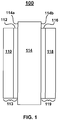
- FIG. 1 a membrane-electrode-assembly (MEA) for an electrochemical device is shown, according to one embodiment of the present invention.
- a MEA according to the embodiment shown in FIG. 1 may be incorporated into an electrochemical device, for example a proton exchange membrane (PEM) fuel cell.
- PEM proton exchange membrane
- a MEA has two electrodes, an anode and a cathode. Each of the electrodes is coated on one side with a thin catalyst layer, and the anode and cathode are separated by a proton exchange membrane (PEM).
- PEM proton exchange membrane
- the MEA is disposed between two flow-field plates, and in operation, hydrogen and air or some other fuel and oxidant are provided to the electrodes of the MEA via channels that are formed in the flow field plates. More particularly, one flow-field plate directs hydrogen to the anode and another flow-field plate directs oxygen in the air to the cathode.
- a catalyst layer facilitates separation of the hydrogen into protons and electrons. Free electrons produced at the anode are conducted as a usable electric current through an external circuit.
- hydrogen protons that have passed through the PEM come together with oxygen in air and electrons that return from the external circuit, to form water and heat.
- the MEA 100 includes a membrane 114 with a first surface 114a and an opposite, second surface 114b.
- An anode 113 comprised of a gas diffusion electrode 110 coated with a catalyst layer 112 is disposed on the first surface 114a of the membrane 114, and a cathode 119 comprised of a gas diffusion electrode 118 coated with a catalyst layer 116 is disposed on the second surface 114b of the membrane.
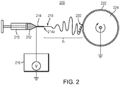
- FIG. 2 schematically shows a system 200 for electrospinning a solution to generate nanofibers and deposit the nanofibers on a collector substrate according to one embodiment of the present invention
- FIG. 3 schematically shows a system 300 for electrospinning a solution to generate nanofibers and deposit the nanofibers on a collector substrate according to another embodiment of the present invention.
- an electrospinning process typically involves applying a high voltage electric field to a spinneret needle containing a polymer solution or polymer melt. Mutual charge repulsion on the surface of the solution overcomes the surface tension such as to produce and eject a thin liquid jet of the solution from the tip of the spinneret needle.
- a solution 212 is delivered from a syringe 210 into a metallic needle 214 having a needle tip 214a.
- the solution 212 is formed according to steps of the method described below with reference to the flow chart of FIG. 4 .
- a voltage produced by a high voltage generator 216 is applied to the metallic needle 214 such that a potential difference is created between the needle tip 214a and a collector substrate 222.
- the collector substrate 222 is disposed on an electrically grounded rotating drum 224. The collector substrate 222 is separated from the needle tip 214a at a predetermined distance d 1 .
- a thin liquid jet 218 of the solution is produced and ejected from the tip 214a of the metallic needle 214 at a flow rate such as to generate electrospun nanofibers 220 and deposit the generated nanofibers 220 on the collector substrate 222 to form a mat comprised of a porous network of nanofibers (see FIG. 5 ).
- a solution 312 is delivered from a syringe 310 into a metallic needle 314 having a needle tip 314a.
- the solution 312 is formed according to steps of the method described below with reference to the flow chart of FIG. 4 .
- a voltage produced by a high voltage generator 316 is applied to the metallic needle 314 such that a potential difference is created between the needle tip 314a and a grounded collector substrate 302.
- the collector substrate 302 is separated from the needle tip 314a by a predetermined distance d 2 .
- a thin liquid jet 318 of the solution is produced and ejected from the tip 314a of the metallic needle 314 at a flow rate such as to generate electrospun nanofibers 320 and deposit the generated nanofibers 320 on the collector substrate 322 to form a mat comprised of a porous network of nanofibers (see FIG. 5 ).
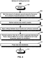
- a flow chart show steps of a method 400 of forming an electrode for an electrochemical device, according to one or more embodiments of the present invention.
- the method begins at step 401 and includes the steps of mixing at least a first amount of a catalyst and a second amount of an ionomer to form a solution, at step 403, and delivering the solution into a metallic needle having a needle tip, at step 405.
- a voltage is applied between the needle tip and a collector substrate positioned at a distance from the needle.
- the solution is extruded from the needle tip at a flow rate such as to generate electrospun nanofibers and deposit the generated nanofibers on the collector substrate, to form a mat including a porous network of nanofibers, at step 409.
- the mat is pressed onto a membrane, at step 411, and the method ends at step 413.
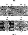
- electrospun nanofiber mats were prepared from a solution of approximately 75 wt% Pt/C, 15 wt% Nafion®, and 10 wt% poly(acrylic acid) in isopropanol/water solvent.
- the nanofibers were deposited on a carbon paper GDL substrate that was fixed to a rotating drum collector.
- the potential difference between the metallic spinneret needle and the drum collector was about 7.0 kV and the spinneret-to-collector distance and flow rate of the solution were fixed at about 10 cm and about 1 mL/hour, respectively.
- the surfaces of the nanofibers 512 are roughened by Pt/C catalyst nanoparticles.
- a uniform distribution of Pt/C catalyst nanoparticles can be seen on the surface of the nanofibers 530 in FIG. 5(c) and 540 in FIG. 5(d) , where the average nanofiber diameter is about 470 nm.
- the morphology of nanofibers (collectively labeled 520) is maintained and the volume density of fibers increased, as shown in the SEM image of the nanofibers 522 in FIG. 5(b) .
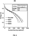
- membrane electrode assemblies were fabricated using a Nafion® 212 membrane, a decal-processed anode (with a Pt loading of about 0.4 mg/cm 2 ) and an electrospun nanofiber cathode, where the Pt cathode loading was about 0.4 mg/cm 2 (designated as ES04 in subsequent figures), or about 0.2 mg/cm 2 (designated as ES02), or about 0.1 mg/cm 2 (designated at ES01).
- a third MEA was prepared by the decal process for both the anode and cathode, where the Pt loading for each electrode was about 0.4 mg/cm 2 (designated as Decal04).
- Table 1 shows the Pt-loading and the electrochemical surface area (ECSA) of the cathode catalyst layer for the 0.4 mg/cm 2 decal cathode MEA and the 0.1 mg/cm 2 electrospun cathode MEA.
- the ECSA of the nanofiber electrodes as determined by in-situ cyclic voltammetry in a fuel cell test fixture at 80°C with fully humidified H 2 and N 2 , was significantly greater than that for a decal-processed cathode.
- FIG. 6 shows a graph 600 of hydrogen/air fuel cell polarization curves for the four different cathode catalyst constructs.
- Cell temperature was 80°C with 125 sccm H 2 and 500 sccm air (zero psi back pressure).
- ES04 delivers about 1080 mA/cm 2 at 0.6V, with a maximum power density of about 705 mW/cm 2 .
- electrospun nanofiber mats were prepared from a solution of approximately 75 wt% Pt/C, 15 wt% Nafion®, and 10 wt% poly(acrylic acid). The nanofibers were deposited on a carbon paper GDL substrate that was fixed to a rotating drum collector. The potential difference between the metallic spinneret needle and the drum collector was about 7.0 kV and the spinneret-to-collector distance and flow rate of the solution were fixed at about 10 cm and about 1 mL/hour, respectively.
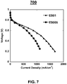
- an electrospun nanofiber catalyst layer was used as the cathode at a Pt loading of 0.05 mg/cm 2 .
- Nanofiber cathodes were hot pressed onto a Nafion 212 membrane at 140°C and 16MPa. Prior to hot-pressing, electrospun nanofiber mats were annealed at 150°C under vacuum for 2 hours. The Pt loading of a nanofiber mat was adjusted by the electrospinning duration and calculated from the total weight of an electrospun mat and the weight-fraction of Pt/C catalyst used for its preparation. After hot pressing the nanofiber electrode onto a Nafion® 212 membrane, the morphology of nanofibers is maintained and the volume density of fibers increased.
- FIG. 7 shows a graph 700 of hydrogen/air fuel cell polarization curves for an electrospun 0.05 mg/cm 2 Pt loading cathode with an electrospun 0.1 mg/cm 2 Pt loading cathode MEA.
- ES005 delivers about 620 mA/cm 2 at 0.6V, with a maximum power density of about 401 mW/cm 2 .
- ultra-low Pt loading is defined as a Pt loading less than 0.10 mg/cm 2 .
- electrospun nanofiber mats were prepared from a solution of approximately 75 wt% Pt/C, 15 wt% Nafion®, and 10 wt% poly(acrylic acid). The nanofibers were deposited on a carbon paper GDL substrate that was fixed to a rotating drum collector. The potential difference between the metallic spinneret needle and the drum collector was about 7.0 kV and the spinneret-to-collector distance and flow rate of the solution were fixed at about 10 cm and about 1 mL/hour, respectively.
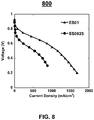
- an electrospun nanofiber catalyst layer was used as the cathode at a Pt loading of 0.025 mg/cm 2 (nanofiber cathodes were hot pressed to Nafion 212 at 140°C and 16MPa). Prior to hot-pressing, electrospun nanofiber mats were annealed at 150°C under vacuum for 2 hours. The Pt loading of a nanofiber mat was adjusted by the electrospinning duration and calculated from its total weight and the weight-fraction of Pt/C catalyst used for its preparation. After hot pressing the nanofiber electrode onto a Nafion® 212 membrane, the morphology of nanofibers is maintained and the volume density of fibers increased.
- FIG. 8 shows a graph 800 of hydrogen/air fuel cell polarization curves for the two different cathode catalyst constructs.
- ES0025 delivers about 235 mA/cm 2 at 0.6V, with a maximum power density of about 302 mW/cm 2 .
- This example further shows that an electrospun nanofiber electrode morphology according to one or more embodiments of the present invention disclosed herein can be created and can be used in a fuel cell MEA to generate power in a PEM fuel cell with ultra-low Pt loading.
- the present invention relates to a method 400 of forming an electrode for an electrochemical device.
- the method includes mixing a first amount of a catalyst, a second amount of an ionomer, and a third amount of a second polymer to form a solution, at step 403.
- the method further includes delivering the formed solution into a metallic needle, at step 405.
- a voltage is applied between the needle tip and a collector substrate, and at step 409, the solution is extruded from the needle tip at a flow rate such as to generate electrospun nanofibers and deposit the generated nanofibers on the collector substrate to form a mat with a porous network of nanofibers, where each nanofiber has distributed particles of the catalyst.
- the method also includes pressing the mat onto a membrane, at step 411.
- the catalyst includes platinum-supported carbon (Pt/C)
- the ionomer includes Nafion®
- the step of forming the solution further includes mixing a third amount of a second polymer with the first amount of catalyst and second amount of ionomer.
- the second polymer includes polyacrylic acid (PAA), and the ratios between the catalyst, ionomer, and second polymer are about 15:3:2 by weight.
- the collector substrate includes a carbon paper or carbon cloth gas diffusion layer disposed on a rotating drum, wherein the collector substrate is separated from the needle tip at a distance of about 10 cm. A voltage of about 7.0 kV is applied between the needle tip and the collector substrate, and the solution is extruded from the needle tip at a flow rate of about 1 mL/hour.
- the nanofibers are formed to have an average diameter of about 470 nm.
- the nanofiber electrode, as formed has a Pt loading in a range from about 0.025 to about 0.4 mg/cm 2 and an electrochemical surface area of about 114 m 2 Pt/g Pt.
- the present invention relates to a nanofiber electrode formed by a method that includes the steps of: mixing at least a first amount of a catalyst and a second amount of an ionomer to form a solution, shown by element 212 in FIG. 2 and element 312 in FIG. 3 ; delivering the solution into a metallic needle, shown by element 214 in FIG. 2 and element 314 in FIG. 3 , that has a corresponding needle tip, shown by element 214a in FIG. 2 and element 314a in FIG. 3 ; applying a voltage between the needle tip and a collector substrate, shown by element 222 in FIG. 2 and element 302 in FIG.
- the present invention relates to a membrane-electrode-assembly (MEA) 100 for an electrochemical device.
- the MEA 100 includes a membrane 114 having a first surface 114a and an opposite, second surface 114b, an anode 113 disposed on the first surface 114a of the membrane 114, and a cathode 119 disposed on the second surface 114b of the membrane 114.
- the cathode 119 is formed by the steps of: mixing at least a first amount of a catalyst and a second amount of an ionomer to form a solution; delivering the solution into a metallic needle having a needle tip; applying a voltage between the needle tip and a collector substrate positioned at a distance from the needle tip; extruding the solution from the needle tip at a flow rate such as to generate electrospun nanofibers and deposit the generated nanofibers on the collector substrate to form a mat having a porous network of nanofibers, where each nanofiber has distributed particles of the catalyst; and pressing the mat onto the second surface of the membrane.
- the nanofibers are formed to have an average diameter of about 470 nm
- the catalyst includes platinum-supported carbon (Pt/C) and the ionomer includes Nafion®.
- Forming the solution further includes mixing a third amount of a second polymer with the first amount of catalyst and second amount of ionomer, wherein the second polymer includes polyacrylic acid (PAA) and the ratios between the catalyst, ionomer, and second polymer are about 15:3:2 by weight.
- PPAA polyacrylic acid
- the collector substrate includes a carbon paper or carbon cloth gas diffusion layer disposed on a rotating drum and the distance between the collector substrate and the needle tip is about 10 cm.
- a voltage of about 7.0 kV is applied between the needle tip and the collector substrate. The solution is extruded from the needle tip at a flow rate of about 1 mL/hour.
- the cathode, as formed has a Pt loading in a range from about 0.025 to about 0.4 mg/cm 2 and an electrochemical surface area of about 114 m 2 Pt/g Pt
- the membrane is ionically conductive and, in one embodiment, the conductive membrane is proton conductive.
- the proton conductive membrane includes a perfluorosulfonic acid (PAA) that includes Nafion®.
- PAA perfluorosulfonic acid
- the membrane is a nanofiber composite membrane.
- the catalyst includes at least one of, or a combination of, Pt particles, Pt alloy particles, Pt on carbon particles, precious metal particles, precious metal on carbon particles, precious metal based alloys, previous metal based alloys on carbon particles, Ag particles, Ni particles, Ag alloy particles, Ni alloy particles, Fe particles, Fe alloy particles, Pd particles, Pd alloy particles, core-shell catalyst particles, and non-platinum group (PGM) fuel cell catalysts.
- PGM platinum group
- the present invention relates to a membrane-electrode-assembly (MEA) 100 for an electrochemical device.
- the MEA 100 includes a membrane 114 having a first surface 114a and an opposite, second surface 114b, and an anode 113 disposed on the first surface 114a of the membrane 114.
- the anode 113 is formed by the steps of: mixing at least a first amount of a catalyst and a second amount of an ionomer to form a solution; delivering the solution into a metallic needle having a needle tip; applying a voltage between the needle tip and a collector substrate positioned at a distance from the needle tip; extruding the solution from the needle tip at a flow rate such as to generate electrospun nanofibers and deposit the generated nanofibers on the collector substrate to form a mat with a porous network of nanofibers, where each nanofiber has a plurality of particles of the catalyst distributed thereon; and pressing the mat onto the first surface 114a of the membrane 114.
- the MEA also includes a cathode 119 disposed on the second surface 114b of the membrane 114.
- forming the solution further includes mixing a third amount of a second polymer with the first amount of catalyst and second amount of ionomer.
Landscapes
- Engineering & Computer Science (AREA)
- Chemical & Material Sciences (AREA)
- General Chemical & Material Sciences (AREA)
- Chemical Kinetics & Catalysis (AREA)
- Electrochemistry (AREA)
- Manufacturing & Machinery (AREA)
- Sustainable Development (AREA)
- Life Sciences & Earth Sciences (AREA)
- Sustainable Energy (AREA)
- Mechanical Engineering (AREA)
- Materials Engineering (AREA)
- Textile Engineering (AREA)
- Crystallography & Structural Chemistry (AREA)
- Dispersion Chemistry (AREA)
- Structural Engineering (AREA)
- Inert Electrodes (AREA)
- Spinning Methods And Devices For Manufacturing Artificial Fibers (AREA)
- Nonwoven Fabrics (AREA)
- Catalysts (AREA)
Claims (15)
- Verfahren (400) der Bildung einer Elektrode für eine elektrochemische Vorrichtung, welches die Schritte aufweist:(a) Mischen (403) zumindest einer ersten Menge eines Katalysators und einer zweiten Menge eines lonomers oder eines ungeladenen Polymers zur Bildung einer Lösung (211; 312);(b) Geben (405) der Lösung in eine Metallnadel (214; 314), die eine Nadelspitze (214a; 314a) aufweist;(c) Anlegen (407) einer Spannung zwischen der Nadelspitze (214a; 314a) und einem Sammelsubstrat (222; 302), das mit einem Abstand (d1; d2) von der Nadelspitze (214a; 314a) angeordnet ist;(d) Abgeben (409) der Lösung (212; 312) von der Nadelspitze mit einer Strömungsrate, um elektro-gesponnene Fasern (220; 320) zu erzeugen und die erzeugten Fasern (220; 320) auf dem Sammelsubstrat (222; 302) abzulagern, um eine Matte zu bilden, die ein poröses Fasernetzwerk aufweist, wobei auf jeder Faser eine Mehrzahl von Partikeln des Katalysators verteilt sind; und(e) Pressen (411) der Matte auf eine Membran (114),
wobei das lonomer oder das ungeladene Polymer von der Fasermatte nicht entfernt wird. - Das Verfahren von Anspruch 1, wobei der Katalysator platingetragenen Kohlenstoff (Pt/C) aufweist, oder/und wobei das lonomer oder ungeladene Polymer Nafion® aufweist.
- Das Verfahren von Anspruch 1, wobei das Bilden der Lösung (212; 312) ferner aufweist, eine dritte Menge eines zweiten Polymers mit der ersten Menge des Katalysators und der zweiten Menge des lonomers oder ungeladenen Polymers zu mischen, wobei das zweite Polymer bevorzugt Polyacrylsäure (PAA) aufweist.
- Das Verfahren von Anspruch 1, wobei die Gewichtsverhältnisse zwischen dem Katalysator, lonomer oder ungeladenen Polymer und zweiten Polymer 15:3:2 betragen.
- Das Verfahren von Anspruch 1,
wobei das Sammelsubstrat (222; 302) eine Kohlepapier- oder eine Kohlenstofftuchgasdiffusionsschicht aufweist,
oder/und
wobei die Membran (114) eine Polymermembran aufweist. - Das Verfahren von Anspruch 1,
wobei das Sammelsubstrat (222; 302) auf einer rotierenden Trommel (224) angeordnet wird,
oder/und
der Abstand (d1; d2) zwischen dem Sammelsubstrat (222; 302) und der Nadelspitze (214a; 314a) 10 cm beträgt;
oder/und
wobei die zwischen der Nadelspitze (214a; 314a) und dem Sammelsubstrat (222; 302) angelegte Spannung 7,0 kV beträgt;
oder/und
die Strömungsrate 1 mL/Stunde beträgt. - Das Verfahren von Anspruch 1,
wobei die Fasern (220; 320) so ausgebildet werden, dass sie einen durchschnittlichen Durchmesser von 470 nm haben,
oder/und
die Elektrode, wie gebildet, eine Pt-Beladung im Bereich von 0,025 bis 0,4 mg/cm2 aufweist,
oder/und
die Elektrode, wie gebildet, eine elektrochemische Oberflächenausdehnung von 114 m2/gpt aufweist. - Das Verfahren von Anspruch 1, wobei die Membran (114) ionisch leitfähig, bevorzugt protonenleitfähig.
- Das Verfahren von Anspruch 7, wobei die protonenleitfähige Membran (114) eine Perfluorsulfonsäure, bevorzugt Nafion® aufweist.
- Das Verfahren von Anspruch 1, wobei die Membran (114) eine Nanofaserkompositmembran ist.
- Das Verfahren von Anspruch 1, wobei der Katalysator Pt-Partikel, Pt-Legierungspartikel, Pt-auf-Kohlepartikeln, Edelmetallpartikel, Edelmetall-auf-Kohlepartikeln, edelmetallbasierte Legierungen, edelmetallbasierte Legierungen auf Kohlepartikeln, Ag-Partikel, Ni-Partikel, Ag-Legierungspartikel, Ni-Legierungspartikel, Fe-Partikel, Fe-Legierungspartikel, Pd-Partikel, Pd-Legierungspartikel, Kernschalenkatalysatorpartikel, Nicht-Platin-Gruppe-Metall (PGM)-Brennstoffzellenkatalysatoren oder eine Kombination davon aufweist.
- Elektrode, die durch das Verfahren (400) von einem der Ansprüche 1 bis 11 gebildet ist.
- Membranelektrodenanordnung (MEA) (100) für eine elektrochemische Vorrichtung, wobei die MEA aufweist:(a) eine Membran (114) mit einer ersten Oberfläche (114a) und einer entgegengesetzten zweiten Oberfläche (114b);(b) eine Anode (113), die auf der ersten Oberfläche (114a) der Membran (114) angeordnet ist;(c) eine Kathode (119), die auf der zweiten Oberfläche (114b) der Membran (114) angeordnet ist; wobei zumindest eine der Anode (113) und der Kathode (119) durch das Verfahren von einem der Ansprüche 1 bis 11 gebildet ist.
- Protonenaustauschmembran(PEM)-Brennstoffzelle, welche aufweist:(a) eine Membranelektrodenanordnung (MEA) (100), welche enthält:(i) eine Membran (114) mit einer ersten Oberfläche (114a) und einer entgegegesetzten zweiten Oberfläche (114b);(ii) einer Anode (113), die auf der ersten Oberfläche (114a) der Membran (114) angeordnet ist; und(iii) einer Kathode (119), die auf der zweiten Oberfläche (114b) der Membran (114) angeordnet ist;(b) eine erste Fließfeldplatte mit Kanälen, die betreibbar sind, um Brennstoff zur Anode (113) zu leiten; und(c) eine zweite Fließfeldplatte mit Kanälen, die betreibbar sind, um ein Oxidationsmittel zur Kathode (119) zu leiten;wobei bevorzugt zumindest eine der Anode (113) und der Kathode (119) durch das Verfahren von einem der Ansprüche 1 bis 11 ausgebildet ist.
- Die Brennstoffzelle von Anspruch 14, wobei die erste Fließfeldplatte betreibbar ist, um Wasserstoff zur Anode (113) zu leiten, und die zweite Fließfeldplatte betreibbar ist, um Sauerstoff zur Kathode (119) zu leiten.
Applications Claiming Priority (2)
| Application Number | Priority Date | Filing Date | Title |
|---|---|---|---|
| US40733210P | 2010-10-27 | 2010-10-27 | |
| PCT/US2011/058088 WO2012058425A2 (en) | 2010-10-27 | 2011-10-27 | Nanofiber electrode and method of forming same |
Publications (3)
| Publication Number | Publication Date |
|---|---|
| EP2633581A2 EP2633581A2 (de) | 2013-09-04 |
| EP2633581A4 EP2633581A4 (de) | 2017-03-15 |
| EP2633581B1 true EP2633581B1 (de) | 2018-12-19 |
Family
ID=45994756
Family Applications (1)
| Application Number | Title | Priority Date | Filing Date |
|---|---|---|---|
| EP11837086.5A Active EP2633581B1 (de) | 2010-10-27 | 2011-10-27 | Nanofaserelektrode und verfahren zu ihrer formung |
Country Status (7)
| Country | Link |
|---|---|
| US (1) | US9905870B2 (de) |
| EP (1) | EP2633581B1 (de) |
| JP (1) | JP5964846B2 (de) |
| KR (1) | KR20140000700A (de) |
| CN (1) | CN103328204B (de) |
| CA (1) | CA2815254A1 (de) |
| WO (1) | WO2012058425A2 (de) |
Families Citing this family (41)
| Publication number | Priority date | Publication date | Assignee | Title |
|---|---|---|---|---|
| WO2017059413A1 (en) * | 2015-10-02 | 2017-04-06 | Vanderbilt University | Nanofiber mats, making methods and applications of same |
| CZ303780B6 (cs) * | 2012-07-27 | 2013-05-02 | Contipro Biotech S.R.O. | Zvláknovací tryska pro výrobu nano a mikrovlákenných materiálu slozených z vláken s koaxiální strukturou |
| US20140051013A1 (en) | 2012-08-14 | 2014-02-20 | Yossef A. Elabd | Ion conducting nanofiber fuel cell electrodes |
| TWI507244B (zh) * | 2013-05-23 | 2015-11-11 | Gunitech Corp | 製造纖維觸媒的方法及其纖維觸媒 |
| EP2887435B1 (de) * | 2013-06-04 | 2017-03-01 | Panasonic Intellectual Property Management Co., Ltd. | Membranelektrodenanordnung, herstellungsverfahren dafür und festpolymerbrennstoffzelle |
| WO2015060655A1 (ko) * | 2013-10-23 | 2015-04-30 | 주식회사 아모그린텍 | 이온교환막을 구비한 탈염용 복합전극, 그의 제조 방법 및 이를 이용한 탈염 장치 |
| US9979028B2 (en) * | 2013-12-13 | 2018-05-22 | GM Global Technology Operations LLC | Conformal thin film of precious metal on a support |
| JP6849434B2 (ja) * | 2014-02-20 | 2021-03-24 | メルク パテント ゲゼルシャフト ミット ベシュレンクテル ハフツングMerck Patent Gesellschaft mit beschraenkter Haftung | 安定な触媒インク配合物、かかるインクの繊維形成における使用方法、およびかかる繊維を含む物品 |
| KR20170062487A (ko) * | 2014-09-24 | 2017-06-07 | 벤더르빌트 유니버시티 | 중합체 용액, 섬유 매트, 및 그것을 갖는 나노섬유 멤브레인-전극-조립체, 및 그의 제조 방법 |
| JP2018508930A (ja) * | 2014-12-24 | 2018-03-29 | スリーエム イノベイティブ プロパティズ カンパニー | 電気化学的装置内の多孔質接着剤ネットワーク |
| US11020939B2 (en) | 2016-05-23 | 2021-06-01 | Vanderbilt University | Nanofiber electrodes, fabricating methods and applications of same |
| KR102664893B1 (ko) | 2016-12-13 | 2024-05-08 | 한양대학교 산학협력단 | 코일-주름 구조를 갖는 복합 섬유, 이를 포함하는 슈퍼 커패시터 및 그 제조 방법. |
| KR101972581B1 (ko) * | 2017-08-23 | 2019-04-29 | (주)엘켐텍 | 나노섬유층을 갖는 기체확산층을 구비한 수전해 막전극접합체 및 그 제조방법 |
| KR101972580B1 (ko) * | 2017-08-23 | 2019-04-29 | (주)엘켐텍 | 웹구조의 전극촉매층을 갖는 전기화학 셀용 막전극접합체의 제조방법 |
| CN109913971A (zh) * | 2017-12-12 | 2019-06-21 | 中国科学院大连化学物理研究所 | 一种多孔复合纳米纤维及其制备方法和应用 |
| CN109930227A (zh) * | 2017-12-18 | 2019-06-25 | 中国科学院大连化学物理研究所 | 一种具有纤维结构的电极材料及制备和应用 |
| JP7069982B2 (ja) * | 2018-04-02 | 2022-05-18 | 株式会社豊田中央研究所 | 不織布 |
| JP2019204700A (ja) * | 2018-05-24 | 2019-11-28 | ロベルト・ボッシュ・ゲゼルシャフト・ミト・ベシュレンクテル・ハフツングRobert Bosch Gmbh | 燃料電池の製造方法 |
| US20210301305A1 (en) | 2018-06-13 | 2021-09-30 | Voyager Therapeutics, Inc. | Engineered untranslated regions (utr) for aav production |
| SG11202100704PA (en) | 2018-07-24 | 2021-02-25 | Voyager Therapeutics Inc | Systems and methods for producing gene therapy formulations |
| US20210348242A1 (en) | 2018-10-04 | 2021-11-11 | Voyager Therapeutics, Inc. | Methods for measuring the titer and potency of viral vector particles |
| CN113166731A (zh) | 2018-10-05 | 2021-07-23 | 沃雅戈治疗公司 | 编码aav生产蛋白的工程化核酸构建体 |
| AU2019360937A1 (en) | 2018-10-15 | 2021-05-20 | Voyager Therapeutics, Inc. | Expression vectors for large-scale production of rAAV in the baculovirus/Sf9 system |
| WO2020096086A1 (ko) * | 2018-11-08 | 2020-05-14 | (주)엘켐텍 | 나노섬유층을 갖는 기체확산층과 이를 구비한 수전해 막전극접합체 및 그 제조방법 |
| WO2020150556A1 (en) | 2019-01-18 | 2020-07-23 | Voyager Therapeutics, Inc. | Methods and systems for producing aav particles |
| EP3962536A1 (de) | 2019-04-29 | 2022-03-09 | Voyager Therapeutics, Inc. | Systeme und verfahren zur herstellung von baculovirusinfizierten insektenzellen (biics) in bioreaktoren |
| CN110071313B (zh) * | 2019-05-05 | 2022-04-01 | 吉林大学 | 聚苯并咪唑基多组分纳米高温质子交换复合膜、制备方法及其应用 |
| EP3970220B1 (de) * | 2019-05-13 | 2023-03-22 | Nikola Corporation | Katalysatorschichten von membran-elektroden-anordnungen und verfahren zu deren herstellung |
| EP4010465A1 (de) | 2019-08-09 | 2022-06-15 | Voyager Therapeutics, Inc. | Zellkulturmedium zur verwendung bei der herstellung von gentherapieprodukten in bioreaktoren |
| TW202122582A (zh) | 2019-08-26 | 2021-06-16 | 美商航海家醫療公司 | 病毒蛋白之控制表現 |
| JP7184011B2 (ja) * | 2019-10-25 | 2022-12-06 | 株式会社豊田中央研究所 | 触媒層 |
| CN110777424B (zh) * | 2019-11-14 | 2023-07-18 | 南京工业职业技术学院 | 一种纳米针尖批量生产装置及制备方法 |
| WO2021114317A1 (zh) * | 2019-12-10 | 2021-06-17 | 中国科学院大连化学物理研究所 | 一种具有纤维结构的电极材料及制备和应用 |
| JP7365885B2 (ja) | 2019-12-13 | 2023-10-20 | 日本バイリーン株式会社 | 繊維シートおよびその製造方法 |
| EP4192514A1 (de) | 2020-08-06 | 2023-06-14 | Voyager Therapeutics, Inc. | Zellkulturmedium zur verwendung bei der herstellung von gentherapieprodukten in bioreaktoren |
| WO2022187548A1 (en) | 2021-03-03 | 2022-09-09 | Voyager Therapeutics, Inc. | Controlled expression of viral proteins |
| US20240141377A1 (en) | 2021-03-03 | 2024-05-02 | Voyager Therapeutics, Inc. | Controlled expression of viral proteins |
| CN113106629A (zh) * | 2021-04-07 | 2021-07-13 | 中国人民解放军国防科技大学 | 一种有序纳米纤维质子交换膜及其制备方法与应用 |
| KR20230108545A (ko) | 2022-01-11 | 2023-07-18 | 주식회사 네이션스 | 알칼라인 수전해 전지 |
| WO2023243449A1 (ja) * | 2022-06-14 | 2023-12-21 | Toppanホールディングス株式会社 | 水電解装置用積層体、水電解装置用膜電極接合体及び水電解装置 |
| WO2024054983A1 (en) | 2022-09-08 | 2024-03-14 | Voyager Therapeutics, Inc. | Controlled expression of viral proteins |
Family Cites Families (11)
| Publication number | Priority date | Publication date | Assignee | Title |
|---|---|---|---|---|
| JP2008521174A (ja) * | 2004-11-16 | 2008-06-19 | バトル、メモリアル、インスティテュート | 燃料電池構成要素の改良に基づく溶液および他の電気化学システムおよびデバイス。 |
| WO2006061993A1 (ja) | 2004-12-07 | 2006-06-15 | Toray Industries, Inc. | 膜電極複合体およびその製造方法、ならびに燃料電池 |
| JP4719015B2 (ja) * | 2006-01-20 | 2011-07-06 | 株式会社東芝 | 電解質膜、膜電極複合体及び燃料電池 |
| JP2007319839A (ja) * | 2006-06-05 | 2007-12-13 | Mitsubishi Chemicals Corp | 繊維状金属酸化物触媒 |
| CN100432307C (zh) | 2006-06-30 | 2008-11-12 | 北京化工大学 | 定向磁性电纺纳米纤维及其制备方法和所用设备 |
| US20080305377A1 (en) * | 2007-03-15 | 2008-12-11 | University Of Rochester | Long metallic nanowires, methods of making, and use thereof in proton exchange membrane fuel cell |
| JP2008243777A (ja) * | 2007-03-29 | 2008-10-09 | Electric Power Dev Co Ltd | 固体高分子電解質型燃料電池およびその膜電極接合体 |
| JPWO2009075357A1 (ja) * | 2007-12-13 | 2011-04-28 | 旭硝子株式会社 | 固体高分子形燃料電池用電極、膜電極接合体および触媒層の製造方法 |
| JP5375022B2 (ja) * | 2008-10-17 | 2013-12-25 | 旭硝子株式会社 | 繊維の製造方法および触媒層の製造方法 |
| FI20086154A0 (fi) * | 2008-12-02 | 2008-12-02 | Valtion Teknillinen | Katalyyttirakenne |
| CN101665232B (zh) * | 2009-09-17 | 2011-11-23 | 中国科学院长春应用化学研究所 | 钯纳米颗粒/碳纳米纤维复合物、制法及其在电催化的应用 |
-
2011
- 2011-10-27 JP JP2013536826A patent/JP5964846B2/ja active Active
- 2011-10-27 CN CN201180062942.7A patent/CN103328204B/zh active Active
- 2011-10-27 US US13/823,968 patent/US9905870B2/en active Active
- 2011-10-27 CA CA2815254A patent/CA2815254A1/en not_active Abandoned
- 2011-10-27 KR KR1020137013313A patent/KR20140000700A/ko not_active Application Discontinuation
- 2011-10-27 WO PCT/US2011/058088 patent/WO2012058425A2/en active Application Filing
- 2011-10-27 EP EP11837086.5A patent/EP2633581B1/de active Active
Non-Patent Citations (1)
| Title |
|---|
| None * |
Also Published As
| Publication number | Publication date |
|---|---|
| JP2014504424A (ja) | 2014-02-20 |
| WO2012058425A3 (en) | 2012-06-14 |
| CN103328204A (zh) | 2013-09-25 |
| US9905870B2 (en) | 2018-02-27 |
| CA2815254A1 (en) | 2012-05-03 |
| KR20140000700A (ko) | 2014-01-03 |
| WO2012058425A2 (en) | 2012-05-03 |
| EP2633581A4 (de) | 2017-03-15 |
| US20130209913A1 (en) | 2013-08-15 |
| EP2633581A2 (de) | 2013-09-04 |
| CN103328204B (zh) | 2016-10-26 |
| JP5964846B2 (ja) | 2016-08-03 |
Similar Documents
| Publication | Publication Date | Title |
|---|---|---|
| EP2633581B1 (de) | Nanofaserelektrode und verfahren zu ihrer formung | |
| Brodt et al. | Fabrication, in-situ performance, and durability of nanofiber fuel cell electrodes | |
| JP2014504424A5 (de) | ||
| US20170250431A1 (en) | Polymer solution, fiber mat, and nanofiber membrane-electrode-assembly therewith, and method of fabricating same | |
| Waldrop et al. | Application of electrospinning for the fabrication of proton-exchange membrane fuel cell electrodes | |
| US20070231470A1 (en) | Methods of producing composite material, filter and diffusion layer of fuel cell | |
| US9876246B2 (en) | Nanofiber membrane-electrode-assembly and method of fabricating same | |
| US20140051013A1 (en) | Ion conducting nanofiber fuel cell electrodes | |
| EP3198673A1 (de) | Polymerlösung, fasermatte und nanofasermembranelektrodenanordnung damit sowie verfahren zur herstellung davon | |
| US20210384493A1 (en) | Composite fiber electrodes and applications of same | |
| US20180269507A1 (en) | Nanofiber mats, making methods and applications of same | |
| US10916783B2 (en) | Separator for fuel cell, method of fabricating the same, and fuel cell electrode assembly | |
| US20180138519A1 (en) | Nanofiber electrode and method of forming same | |
| JP2016207514A (ja) | 燃料電池用電解質膜とそれを用いた燃料電池 | |
| KR102097507B1 (ko) | 고분자 전해질 연료전지용 수소이온 전도성 고분자 섬유 매트릭스 내장 전극 및 이를 포함하는 막-전극 접합체 | |
| Slack et al. | Electrospun nanofiber fuel cell MEA cathodes with PtCo/C catalyst | |
| Pintauro et al. | Technical University of Denmark [] T U | |
| Pintauro et al. | Nanofiber membrane-electrode-assembly and method of fabricating same | |
| KR20190019520A (ko) | 전기분무방사를 이용한 고분자 연료전지 전극의 제조방법 및 그를 이용하여 제조한 고분자 연료전지 전극 | |
| US11302946B2 (en) | Manufacturing method for membrane electrode assembly, and stacked body | |
| KR20240067020A (ko) | 연료 전지용 막-전극 어셈블리, 및 이의 제조 방법 | |
| Gao et al. | Electrospun catalyst layers using short-side-chain ionomer for low platinum and high performance PEMFCs | |
| Brodt et al. | Nanofiber Electrodes for High Power PEM Fuel Cells | |
| KR20160029598A (ko) | 막전극 접합체 및 이를 포함하는 연료전지 | |
| CN115621472A (zh) | 一种复合电极结构及其制备方法 |
Legal Events
| Date | Code | Title | Description |
|---|---|---|---|
| PUAI | Public reference made under article 153(3) epc to a published international application that has entered the european phase |
Free format text: ORIGINAL CODE: 0009012 |
|
| 17P | Request for examination filed |
Effective date: 20130426 |
|
| AK | Designated contracting states |
Kind code of ref document: A2 Designated state(s): AL AT BE BG CH CY CZ DE DK EE ES FI FR GB GR HR HU IE IS IT LI LT LU LV MC MK MT NL NO PL PT RO RS SE SI SK SM TR |
|
| DAX | Request for extension of the european patent (deleted) | ||
| A4 | Supplementary search report drawn up and despatched |
Effective date: 20170214 |
|
| RIC1 | Information provided on ipc code assigned before grant |
Ipc: H01M 4/92 20060101ALI20170208BHEP Ipc: H01M 4/88 20060101ALI20170208BHEP Ipc: H01M 4/90 20060101ALI20170208BHEP Ipc: H01M 8/1039 20160101ALI20170208BHEP Ipc: H01M 8/1004 20160101ALI20170208BHEP Ipc: H01M 8/1018 20160101ALN20170208BHEP Ipc: H01M 8/10 20160101AFI20170208BHEP Ipc: B32B 13/02 20060101ALI20170208BHEP Ipc: D01D 5/00 20060101ALI20170208BHEP Ipc: B29C 47/00 20060101ALI20170208BHEP Ipc: H01M 8/102 20160101ALI20170208BHEP |
|
| GRAP | Despatch of communication of intention to grant a patent |
Free format text: ORIGINAL CODE: EPIDOSNIGR1 |
|
| STAA | Information on the status of an ep patent application or granted ep patent |
Free format text: STATUS: GRANT OF PATENT IS INTENDED |
|
| RIC1 | Information provided on ipc code assigned before grant |
Ipc: H01M 8/1018 20160101ALN20180612BHEP Ipc: H01M 8/10 20060101AFI20180612BHEP Ipc: H01M 8/1039 20160101ALI20180612BHEP Ipc: H01M 4/90 20060101ALI20180612BHEP Ipc: H01M 4/88 20060101ALI20180612BHEP Ipc: H01M 4/92 20060101ALI20180612BHEP Ipc: H01M 8/1004 20160101ALI20180612BHEP Ipc: B32B 13/02 20060101ALI20180612BHEP Ipc: B29C 47/00 20060101ALI20180612BHEP Ipc: H01M 8/102 20160101ALI20180612BHEP Ipc: D01D 5/00 20060101ALI20180612BHEP |
|
| INTG | Intention to grant announced |
Effective date: 20180705 |
|
| GRAS | Grant fee paid |
Free format text: ORIGINAL CODE: EPIDOSNIGR3 |
|
| GRAA | (expected) grant |
Free format text: ORIGINAL CODE: 0009210 |
|
| STAA | Information on the status of an ep patent application or granted ep patent |
Free format text: STATUS: THE PATENT HAS BEEN GRANTED |
|
| AK | Designated contracting states |
Kind code of ref document: B1 Designated state(s): AL AT BE BG CH CY CZ DE DK EE ES FI FR GB GR HR HU IE IS IT LI LT LU LV MC MK MT NL NO PL PT RO RS SE SI SK SM TR |
|
| REG | Reference to a national code |
Ref country code: GB Ref legal event code: FG4D |
|
| REG | Reference to a national code |
Ref country code: CH Ref legal event code: EP |
|
| REG | Reference to a national code |
Ref country code: IE Ref legal event code: FG4D |
|
| REG | Reference to a national code |
Ref country code: DE Ref legal event code: R096 Ref document number: 602011055017 Country of ref document: DE |
|
| REG | Reference to a national code |
Ref country code: AT Ref legal event code: REF Ref document number: 1079652 Country of ref document: AT Kind code of ref document: T Effective date: 20190115 |
|
| REG | Reference to a national code |
Ref country code: NL Ref legal event code: MP Effective date: 20181219 |
|
| PG25 | Lapsed in a contracting state [announced via postgrant information from national office to epo] |
Ref country code: BG Free format text: LAPSE BECAUSE OF FAILURE TO SUBMIT A TRANSLATION OF THE DESCRIPTION OR TO PAY THE FEE WITHIN THE PRESCRIBED TIME-LIMIT Effective date: 20190319 Ref country code: FI Free format text: LAPSE BECAUSE OF FAILURE TO SUBMIT A TRANSLATION OF THE DESCRIPTION OR TO PAY THE FEE WITHIN THE PRESCRIBED TIME-LIMIT Effective date: 20181219 Ref country code: LV Free format text: LAPSE BECAUSE OF FAILURE TO SUBMIT A TRANSLATION OF THE DESCRIPTION OR TO PAY THE FEE WITHIN THE PRESCRIBED TIME-LIMIT Effective date: 20181219 Ref country code: HR Free format text: LAPSE BECAUSE OF FAILURE TO SUBMIT A TRANSLATION OF THE DESCRIPTION OR TO PAY THE FEE WITHIN THE PRESCRIBED TIME-LIMIT Effective date: 20181219 Ref country code: LT Free format text: LAPSE BECAUSE OF FAILURE TO SUBMIT A TRANSLATION OF THE DESCRIPTION OR TO PAY THE FEE WITHIN THE PRESCRIBED TIME-LIMIT Effective date: 20181219 Ref country code: NO Free format text: LAPSE BECAUSE OF FAILURE TO SUBMIT A TRANSLATION OF THE DESCRIPTION OR TO PAY THE FEE WITHIN THE PRESCRIBED TIME-LIMIT Effective date: 20190319 |
|
| REG | Reference to a national code |
Ref country code: LT Ref legal event code: MG4D |
|
| REG | Reference to a national code |
Ref country code: AT Ref legal event code: MK05 Ref document number: 1079652 Country of ref document: AT Kind code of ref document: T Effective date: 20181219 |
|
| PG25 | Lapsed in a contracting state [announced via postgrant information from national office to epo] |
Ref country code: AL Free format text: LAPSE BECAUSE OF FAILURE TO SUBMIT A TRANSLATION OF THE DESCRIPTION OR TO PAY THE FEE WITHIN THE PRESCRIBED TIME-LIMIT Effective date: 20181219 Ref country code: RS Free format text: LAPSE BECAUSE OF FAILURE TO SUBMIT A TRANSLATION OF THE DESCRIPTION OR TO PAY THE FEE WITHIN THE PRESCRIBED TIME-LIMIT Effective date: 20181219 Ref country code: SE Free format text: LAPSE BECAUSE OF FAILURE TO SUBMIT A TRANSLATION OF THE DESCRIPTION OR TO PAY THE FEE WITHIN THE PRESCRIBED TIME-LIMIT Effective date: 20181219 Ref country code: GR Free format text: LAPSE BECAUSE OF FAILURE TO SUBMIT A TRANSLATION OF THE DESCRIPTION OR TO PAY THE FEE WITHIN THE PRESCRIBED TIME-LIMIT Effective date: 20190320 |
|
| PG25 | Lapsed in a contracting state [announced via postgrant information from national office to epo] |
Ref country code: NL Free format text: LAPSE BECAUSE OF FAILURE TO SUBMIT A TRANSLATION OF THE DESCRIPTION OR TO PAY THE FEE WITHIN THE PRESCRIBED TIME-LIMIT Effective date: 20181219 |
|
| PG25 | Lapsed in a contracting state [announced via postgrant information from national office to epo] |
Ref country code: CZ Free format text: LAPSE BECAUSE OF FAILURE TO SUBMIT A TRANSLATION OF THE DESCRIPTION OR TO PAY THE FEE WITHIN THE PRESCRIBED TIME-LIMIT Effective date: 20181219 Ref country code: IT Free format text: LAPSE BECAUSE OF FAILURE TO SUBMIT A TRANSLATION OF THE DESCRIPTION OR TO PAY THE FEE WITHIN THE PRESCRIBED TIME-LIMIT Effective date: 20181219 Ref country code: ES Free format text: LAPSE BECAUSE OF FAILURE TO SUBMIT A TRANSLATION OF THE DESCRIPTION OR TO PAY THE FEE WITHIN THE PRESCRIBED TIME-LIMIT Effective date: 20181219 Ref country code: PT Free format text: LAPSE BECAUSE OF FAILURE TO SUBMIT A TRANSLATION OF THE DESCRIPTION OR TO PAY THE FEE WITHIN THE PRESCRIBED TIME-LIMIT Effective date: 20190419 Ref country code: PL Free format text: LAPSE BECAUSE OF FAILURE TO SUBMIT A TRANSLATION OF THE DESCRIPTION OR TO PAY THE FEE WITHIN THE PRESCRIBED TIME-LIMIT Effective date: 20181219 |
|
| PG25 | Lapsed in a contracting state [announced via postgrant information from national office to epo] |
Ref country code: EE Free format text: LAPSE BECAUSE OF FAILURE TO SUBMIT A TRANSLATION OF THE DESCRIPTION OR TO PAY THE FEE WITHIN THE PRESCRIBED TIME-LIMIT Effective date: 20181219 Ref country code: SM Free format text: LAPSE BECAUSE OF FAILURE TO SUBMIT A TRANSLATION OF THE DESCRIPTION OR TO PAY THE FEE WITHIN THE PRESCRIBED TIME-LIMIT Effective date: 20181219 Ref country code: SK Free format text: LAPSE BECAUSE OF FAILURE TO SUBMIT A TRANSLATION OF THE DESCRIPTION OR TO PAY THE FEE WITHIN THE PRESCRIBED TIME-LIMIT Effective date: 20181219 Ref country code: IS Free format text: LAPSE BECAUSE OF FAILURE TO SUBMIT A TRANSLATION OF THE DESCRIPTION OR TO PAY THE FEE WITHIN THE PRESCRIBED TIME-LIMIT Effective date: 20190419 Ref country code: RO Free format text: LAPSE BECAUSE OF FAILURE TO SUBMIT A TRANSLATION OF THE DESCRIPTION OR TO PAY THE FEE WITHIN THE PRESCRIBED TIME-LIMIT Effective date: 20181219 |
|
| REG | Reference to a national code |
Ref country code: DE Ref legal event code: R097 Ref document number: 602011055017 Country of ref document: DE |
|
| PLBE | No opposition filed within time limit |
Free format text: ORIGINAL CODE: 0009261 |
|
| STAA | Information on the status of an ep patent application or granted ep patent |
Free format text: STATUS: NO OPPOSITION FILED WITHIN TIME LIMIT |
|
| PG25 | Lapsed in a contracting state [announced via postgrant information from national office to epo] |
Ref country code: AT Free format text: LAPSE BECAUSE OF FAILURE TO SUBMIT A TRANSLATION OF THE DESCRIPTION OR TO PAY THE FEE WITHIN THE PRESCRIBED TIME-LIMIT Effective date: 20181219 Ref country code: DK Free format text: LAPSE BECAUSE OF FAILURE TO SUBMIT A TRANSLATION OF THE DESCRIPTION OR TO PAY THE FEE WITHIN THE PRESCRIBED TIME-LIMIT Effective date: 20181219 |
|
| 26N | No opposition filed |
Effective date: 20190920 |
|
| PG25 | Lapsed in a contracting state [announced via postgrant information from national office to epo] |
Ref country code: SI Free format text: LAPSE BECAUSE OF FAILURE TO SUBMIT A TRANSLATION OF THE DESCRIPTION OR TO PAY THE FEE WITHIN THE PRESCRIBED TIME-LIMIT Effective date: 20181219 |
|
| PG25 | Lapsed in a contracting state [announced via postgrant information from national office to epo] |
Ref country code: TR Free format text: LAPSE BECAUSE OF FAILURE TO SUBMIT A TRANSLATION OF THE DESCRIPTION OR TO PAY THE FEE WITHIN THE PRESCRIBED TIME-LIMIT Effective date: 20181219 |
|
| PG25 | Lapsed in a contracting state [announced via postgrant information from national office to epo] |
Ref country code: MC Free format text: LAPSE BECAUSE OF FAILURE TO SUBMIT A TRANSLATION OF THE DESCRIPTION OR TO PAY THE FEE WITHIN THE PRESCRIBED TIME-LIMIT Effective date: 20181219 |
|
| REG | Reference to a national code |
Ref country code: CH Ref legal event code: PL |
|
| PG25 | Lapsed in a contracting state [announced via postgrant information from national office to epo] |
Ref country code: LU Free format text: LAPSE BECAUSE OF NON-PAYMENT OF DUE FEES Effective date: 20191027 Ref country code: LI Free format text: LAPSE BECAUSE OF NON-PAYMENT OF DUE FEES Effective date: 20191031 Ref country code: CH Free format text: LAPSE BECAUSE OF NON-PAYMENT OF DUE FEES Effective date: 20191031 |
|
| REG | Reference to a national code |
Ref country code: BE Ref legal event code: MM Effective date: 20191031 |
|
| PG25 | Lapsed in a contracting state [announced via postgrant information from national office to epo] |
Ref country code: BE Free format text: LAPSE BECAUSE OF NON-PAYMENT OF DUE FEES Effective date: 20191031 |
|
| PG25 | Lapsed in a contracting state [announced via postgrant information from national office to epo] |
Ref country code: IE Free format text: LAPSE BECAUSE OF NON-PAYMENT OF DUE FEES Effective date: 20191027 |
|
| PG25 | Lapsed in a contracting state [announced via postgrant information from national office to epo] |
Ref country code: CY Free format text: LAPSE BECAUSE OF FAILURE TO SUBMIT A TRANSLATION OF THE DESCRIPTION OR TO PAY THE FEE WITHIN THE PRESCRIBED TIME-LIMIT Effective date: 20181219 |
|
| PG25 | Lapsed in a contracting state [announced via postgrant information from national office to epo] |
Ref country code: HU Free format text: LAPSE BECAUSE OF FAILURE TO SUBMIT A TRANSLATION OF THE DESCRIPTION OR TO PAY THE FEE WITHIN THE PRESCRIBED TIME-LIMIT; INVALID AB INITIO Effective date: 20111027 Ref country code: MT Free format text: LAPSE BECAUSE OF FAILURE TO SUBMIT A TRANSLATION OF THE DESCRIPTION OR TO PAY THE FEE WITHIN THE PRESCRIBED TIME-LIMIT Effective date: 20181219 |
|
| PG25 | Lapsed in a contracting state [announced via postgrant information from national office to epo] |
Ref country code: MK Free format text: LAPSE BECAUSE OF FAILURE TO SUBMIT A TRANSLATION OF THE DESCRIPTION OR TO PAY THE FEE WITHIN THE PRESCRIBED TIME-LIMIT Effective date: 20181219 |
|
| PGFP | Annual fee paid to national office [announced via postgrant information from national office to epo] |
Ref country code: FR Payment date: 20221025 Year of fee payment: 12 |
|
| PGFP | Annual fee paid to national office [announced via postgrant information from national office to epo] |
Ref country code: GB Payment date: 20221027 Year of fee payment: 12 Ref country code: DE Payment date: 20221027 Year of fee payment: 12 |
|
| P01 | Opt-out of the competence of the unified patent court (upc) registered |
Effective date: 20230525 |