EP2624943B1 - Vorrichtung zur behandlung einer flüssigkeit und verfahren zum behandeln einer suspension - Google Patents
Vorrichtung zur behandlung einer flüssigkeit und verfahren zum behandeln einer suspension Download PDFInfo
- Publication number
- EP2624943B1 EP2624943B1 EP11767637.9A EP11767637A EP2624943B1 EP 2624943 B1 EP2624943 B1 EP 2624943B1 EP 11767637 A EP11767637 A EP 11767637A EP 2624943 B1 EP2624943 B1 EP 2624943B1
- Authority
- EP
- European Patent Office
- Prior art keywords
- liquid
- treating
- cavitation
- cavitation element
- passage openings
- Prior art date
- Legal status (The legal status is an assumption and is not a legal conclusion. Google has not performed a legal analysis and makes no representation as to the accuracy of the status listed.)
- Not-in-force
Links
- 239000007788 liquid Substances 0.000 title claims description 72
- 238000000034 method Methods 0.000 title claims description 26
- 239000000725 suspension Substances 0.000 title claims description 20
- 239000002245 particle Substances 0.000 claims description 9
- 239000002351 wastewater Substances 0.000 claims description 7
- 238000002604 ultrasonography Methods 0.000 claims description 6
- 239000003973 paint Substances 0.000 claims description 5
- 241000276489 Merlangius merlangus Species 0.000 claims description 3
- 239000011248 coating agent Substances 0.000 claims description 3
- 238000000576 coating method Methods 0.000 claims description 3
- 230000001788 irregular Effects 0.000 claims description 3
- 239000004922 lacquer Substances 0.000 claims 1
- 239000007789 gas Substances 0.000 description 36
- 230000000694 effects Effects 0.000 description 5
- 238000011068 loading method Methods 0.000 description 5
- 239000007787 solid Substances 0.000 description 4
- XLYOFNOQVPJJNP-UHFFFAOYSA-N water Substances O XLYOFNOQVPJJNP-UHFFFAOYSA-N 0.000 description 4
- 239000003651 drinking water Substances 0.000 description 3
- 239000012530 fluid Substances 0.000 description 3
- 238000004065 wastewater treatment Methods 0.000 description 3
- 238000007792 addition Methods 0.000 description 2
- 230000009286 beneficial effect Effects 0.000 description 2
- 230000002925 chemical effect Effects 0.000 description 2
- 235000020188 drinking water Nutrition 0.000 description 2
- 230000002349 favourable effect Effects 0.000 description 2
- 239000007791 liquid phase Substances 0.000 description 2
- 238000004519 manufacturing process Methods 0.000 description 2
- 239000002184 metal Substances 0.000 description 2
- 230000002093 peripheral effect Effects 0.000 description 2
- 239000000049 pigment Substances 0.000 description 2
- 239000000126 substance Substances 0.000 description 2
- 241000894006 Bacteria Species 0.000 description 1
- MYMOFIZGZYHOMD-UHFFFAOYSA-N Dioxygen Chemical compound O=O MYMOFIZGZYHOMD-UHFFFAOYSA-N 0.000 description 1
- CBENFWSGALASAD-UHFFFAOYSA-N Ozone Chemical compound [O-][O+]=O CBENFWSGALASAD-UHFFFAOYSA-N 0.000 description 1
- 238000003302 UV-light treatment Methods 0.000 description 1
- 241000700605 Viruses Species 0.000 description 1
- 230000001133 acceleration Effects 0.000 description 1
- QVGXLLKOCUKJST-UHFFFAOYSA-N atomic oxygen Chemical compound [O] QVGXLLKOCUKJST-UHFFFAOYSA-N 0.000 description 1
- 244000052616 bacterial pathogen Species 0.000 description 1
- 230000015572 biosynthetic process Effects 0.000 description 1
- 238000006243 chemical reaction Methods 0.000 description 1
- 239000000470 constituent Substances 0.000 description 1
- 239000000645 desinfectant Substances 0.000 description 1
- 238000004090 dissolution Methods 0.000 description 1
- 230000035622 drinking Effects 0.000 description 1
- 239000003792 electrolyte Substances 0.000 description 1
- 231100000507 endocrine disrupting Toxicity 0.000 description 1
- 230000002538 fungal effect Effects 0.000 description 1
- 238000000227 grinding Methods 0.000 description 1
- 239000011859 microparticle Substances 0.000 description 1
- 238000002156 mixing Methods 0.000 description 1
- 238000012986 modification Methods 0.000 description 1
- 230000004048 modification Effects 0.000 description 1
- 239000001301 oxygen Substances 0.000 description 1
- 229910052760 oxygen Inorganic materials 0.000 description 1
- 108090000623 proteins and genes Proteins 0.000 description 1
- 102000004169 proteins and genes Human genes 0.000 description 1
- 238000005086 pumping Methods 0.000 description 1
- 238000000746 purification Methods 0.000 description 1
- 238000010008 shearing Methods 0.000 description 1
- 239000010802 sludge Substances 0.000 description 1
- 238000000527 sonication Methods 0.000 description 1
- 230000001954 sterilising effect Effects 0.000 description 1
- 238000009210 therapy by ultrasound Methods 0.000 description 1
- 239000003053 toxin Substances 0.000 description 1
- 231100000765 toxin Toxicity 0.000 description 1
- 108700012359 toxins Proteins 0.000 description 1
- 235000020681 well water Nutrition 0.000 description 1
- 239000002349 well water Substances 0.000 description 1
Images



Classifications
-
- B—PERFORMING OPERATIONS; TRANSPORTING
- B01—PHYSICAL OR CHEMICAL PROCESSES OR APPARATUS IN GENERAL
- B01F—MIXING, e.g. DISSOLVING, EMULSIFYING OR DISPERSING
- B01F27/00—Mixers with rotary stirring devices in fixed receptacles; Kneaders
-
- C—CHEMISTRY; METALLURGY
- C09—DYES; PAINTS; POLISHES; NATURAL RESINS; ADHESIVES; COMPOSITIONS NOT OTHERWISE PROVIDED FOR; APPLICATIONS OF MATERIALS NOT OTHERWISE PROVIDED FOR
- C09D—COATING COMPOSITIONS, e.g. PAINTS, VARNISHES OR LACQUERS; FILLING PASTES; CHEMICAL PAINT OR INK REMOVERS; INKS; CORRECTING FLUIDS; WOODSTAINS; PASTES OR SOLIDS FOR COLOURING OR PRINTING; USE OF MATERIALS THEREFOR
- C09D5/00—Coating compositions, e.g. paints, varnishes or lacquers, characterised by their physical nature or the effects produced; Filling pastes
-
- B—PERFORMING OPERATIONS; TRANSPORTING
- B01—PHYSICAL OR CHEMICAL PROCESSES OR APPARATUS IN GENERAL
- B01F—MIXING, e.g. DISSOLVING, EMULSIFYING OR DISPERSING
- B01F23/00—Mixing according to the phases to be mixed, e.g. dispersing or emulsifying
- B01F23/20—Mixing gases with liquids
- B01F23/23—Mixing gases with liquids by introducing gases into liquid media, e.g. for producing aerated liquids
- B01F23/233—Mixing gases with liquids by introducing gases into liquid media, e.g. for producing aerated liquids using driven stirrers with completely immersed stirring elements
- B01F23/2331—Mixing gases with liquids by introducing gases into liquid media, e.g. for producing aerated liquids using driven stirrers with completely immersed stirring elements characterised by the introduction of the gas along the axis of the stirrer or along the stirrer elements
- B01F23/23313—Mixing gases with liquids by introducing gases into liquid media, e.g. for producing aerated liquids using driven stirrers with completely immersed stirring elements characterised by the introduction of the gas along the axis of the stirrer or along the stirrer elements through a separate conduit substantially parallel with the stirrer axis
-
- B—PERFORMING OPERATIONS; TRANSPORTING
- B01—PHYSICAL OR CHEMICAL PROCESSES OR APPARATUS IN GENERAL
- B01F—MIXING, e.g. DISSOLVING, EMULSIFYING OR DISPERSING
- B01F23/00—Mixing according to the phases to be mixed, e.g. dispersing or emulsifying
- B01F23/20—Mixing gases with liquids
-
- B—PERFORMING OPERATIONS; TRANSPORTING
- B01—PHYSICAL OR CHEMICAL PROCESSES OR APPARATUS IN GENERAL
- B01F—MIXING, e.g. DISSOLVING, EMULSIFYING OR DISPERSING
- B01F23/00—Mixing according to the phases to be mixed, e.g. dispersing or emulsifying
- B01F23/20—Mixing gases with liquids
- B01F23/23—Mixing gases with liquids by introducing gases into liquid media, e.g. for producing aerated liquids
- B01F23/2319—Methods of introducing gases into liquid media
-
- B—PERFORMING OPERATIONS; TRANSPORTING
- B01—PHYSICAL OR CHEMICAL PROCESSES OR APPARATUS IN GENERAL
- B01F—MIXING, e.g. DISSOLVING, EMULSIFYING OR DISPERSING
- B01F23/00—Mixing according to the phases to be mixed, e.g. dispersing or emulsifying
- B01F23/20—Mixing gases with liquids
- B01F23/23—Mixing gases with liquids by introducing gases into liquid media, e.g. for producing aerated liquids
- B01F23/232—Mixing gases with liquids by introducing gases into liquid media, e.g. for producing aerated liquids using flow-mixing means for introducing the gases, e.g. baffles
-
- B—PERFORMING OPERATIONS; TRANSPORTING
- B01—PHYSICAL OR CHEMICAL PROCESSES OR APPARATUS IN GENERAL
- B01F—MIXING, e.g. DISSOLVING, EMULSIFYING OR DISPERSING
- B01F23/00—Mixing according to the phases to be mixed, e.g. dispersing or emulsifying
- B01F23/20—Mixing gases with liquids
- B01F23/23—Mixing gases with liquids by introducing gases into liquid media, e.g. for producing aerated liquids
- B01F23/233—Mixing gases with liquids by introducing gases into liquid media, e.g. for producing aerated liquids using driven stirrers with completely immersed stirring elements
- B01F23/2331—Mixing gases with liquids by introducing gases into liquid media, e.g. for producing aerated liquids using driven stirrers with completely immersed stirring elements characterised by the introduction of the gas along the axis of the stirrer or along the stirrer elements
-
- B—PERFORMING OPERATIONS; TRANSPORTING
- B01—PHYSICAL OR CHEMICAL PROCESSES OR APPARATUS IN GENERAL
- B01F—MIXING, e.g. DISSOLVING, EMULSIFYING OR DISPERSING
- B01F23/00—Mixing according to the phases to be mixed, e.g. dispersing or emulsifying
- B01F23/20—Mixing gases with liquids
- B01F23/23—Mixing gases with liquids by introducing gases into liquid media, e.g. for producing aerated liquids
- B01F23/233—Mixing gases with liquids by introducing gases into liquid media, e.g. for producing aerated liquids using driven stirrers with completely immersed stirring elements
- B01F23/2336—Mixing gases with liquids by introducing gases into liquid media, e.g. for producing aerated liquids using driven stirrers with completely immersed stirring elements characterised by the location of the place of introduction of the gas relative to the stirrer
- B01F23/23363—Mixing gases with liquids by introducing gases into liquid media, e.g. for producing aerated liquids using driven stirrers with completely immersed stirring elements characterised by the location of the place of introduction of the gas relative to the stirrer the gas being introduced above the stirrer
-
- B—PERFORMING OPERATIONS; TRANSPORTING
- B01—PHYSICAL OR CHEMICAL PROCESSES OR APPARATUS IN GENERAL
- B01F—MIXING, e.g. DISSOLVING, EMULSIFYING OR DISPERSING
- B01F23/00—Mixing according to the phases to be mixed, e.g. dispersing or emulsifying
- B01F23/20—Mixing gases with liquids
- B01F23/23—Mixing gases with liquids by introducing gases into liquid media, e.g. for producing aerated liquids
- B01F23/238—Mixing gases with liquids by introducing gases into liquid media, e.g. for producing aerated liquids using vibrations, electrical or magnetic energy, radiations
-
- B—PERFORMING OPERATIONS; TRANSPORTING
- B01—PHYSICAL OR CHEMICAL PROCESSES OR APPARATUS IN GENERAL
- B01F—MIXING, e.g. DISSOLVING, EMULSIFYING OR DISPERSING
- B01F27/00—Mixers with rotary stirring devices in fixed receptacles; Kneaders
- B01F27/05—Stirrers
- B01F27/11—Stirrers characterised by the configuration of the stirrers
- B01F27/115—Stirrers characterised by the configuration of the stirrers comprising discs or disc-like elements essentially perpendicular to the stirrer shaft axis
- B01F27/1151—Stirrers characterised by the configuration of the stirrers comprising discs or disc-like elements essentially perpendicular to the stirrer shaft axis with holes on the surface
-
- B—PERFORMING OPERATIONS; TRANSPORTING
- B01—PHYSICAL OR CHEMICAL PROCESSES OR APPARATUS IN GENERAL
- B01F—MIXING, e.g. DISSOLVING, EMULSIFYING OR DISPERSING
- B01F27/00—Mixers with rotary stirring devices in fixed receptacles; Kneaders
- B01F27/50—Pipe mixers, i.e. mixers wherein the materials to be mixed flow continuously through pipes, e.g. column mixers
-
- B—PERFORMING OPERATIONS; TRANSPORTING
- B01—PHYSICAL OR CHEMICAL PROCESSES OR APPARATUS IN GENERAL
- B01F—MIXING, e.g. DISSOLVING, EMULSIFYING OR DISPERSING
- B01F31/00—Mixers with shaking, oscillating, or vibrating mechanisms
- B01F31/80—Mixing by means of high-frequency vibrations above one kHz, e.g. ultrasonic vibrations
-
- B—PERFORMING OPERATIONS; TRANSPORTING
- B01—PHYSICAL OR CHEMICAL PROCESSES OR APPARATUS IN GENERAL
- B01J—CHEMICAL OR PHYSICAL PROCESSES, e.g. CATALYSIS OR COLLOID CHEMISTRY; THEIR RELEVANT APPARATUS
- B01J19/00—Chemical, physical or physico-chemical processes in general; Their relevant apparatus
- B01J19/008—Processes for carrying out reactions under cavitation conditions
Definitions
- the invention relates to a device for the treatment of a liquid.
- the invention relates to an apparatus and a method for treating a suspension.
- the loading of a liquid with gas is advantageous for a variety of purposes. For example, it allows chemical reactions between the gas and the liquid or between the gas and substances contained in the liquid.
- One possible application is in the treatment of water, both drinking water and wastewater, where the introduction of correspondingly reactive gases can reduce the germ burden.
- a device for treating a liquid with a mechanical cavitation element arranged in a space and a gas supply device which extends through the cavitation element.
- the apparatus further includes an acoustic power converter that emits sound waves directly into the room.
- the movements of the Kavitationselements provide a mixing of the supplied gas with the liquid to be treated, in which the average bubble size is still relatively large.
- the acoustic power converter simultaneously introduces sound waves directly into the liquid, thereby further reducing the mean bubble size throughout the liquid.
- the power converter In order to achieve a sonochemical solution of the gas in the liquid with the known device and the known method, in which a predominant proportion of the gas is in molecularly dispersively dissolved form, the power converter must be designed as an ultrasonic generator, the frequencies in a range between 400 and 1500 kHz, preferably between 600 and 1200 kHz.
- D1 From the publication script FR 2 640 328 A1 , hereinafter referred to as D1, a device for the treatment of a liquid is known which has a space and a pump wheel rotating therein.
- the room is in the area of Kavitationselements with a cross section with different, in particular spiral curves, extended to the output formed.
- the publication font DE 3912 517 A1 discloses a method and apparatus for conveying and separating the constituents of a fluid, in particular a suspension.
- the focus is on the promotion of a sludge or a contaminated liquid, cavitation is used.
- the space of this device is circular.
- the object of the invention is to make the loading of a liquid with gas even more efficient.
- the device according to the invention for the treatment of a liquid comprises a space and a rotatable cavitation element arranged in space, in particular in the form of a flow body.
- the space in the area of the cavitation element has a cross section with different curves.
- This aspect of the invention is based on the finding that a cross section with different curves on the one hand counteracts an undesired rotational flow of the liquid around the axis of rotation of the cavitation element, but on the other hand avoids "dead" corners in which only little liquid exchange takes place.
- the inventive cross-sectional shape of the space rather supports the formation of local turbulence with high flow velocities, which significantly increases the cavitation effect.
- the cross section of the space has a basic shape of a polygon with rounded corners.
- the rounded corners effectively prevent fluid build-up in the corners.
- the sides of the polygonal basic form are preferably convex.
- a design of the space is advantageous in which the basic shape of the space cross-section is that of a regular polygon.
- a space whose cross-section has a trilobular shape.
- Such a shape differs significantly from a circular shape, which would favor an undesirable rotational flow, but still has wall sections which extend approximately tangentially to a generally circular-disk-shaped cavitation.
- the device according to the invention for the treatment of a liquid comprises a space and a substantially disc-shaped cavitation element arranged in space.
- the cavitation element has (preferably elongated) passage openings whose inner walls are rounded.
- This aspect of the invention is based on the recognition that such a shape of the passage openings with rapid rotation of the Kavitationselements allows optimal acceleration of the liquid, without causing undesirable clipping of the liquid.
- the passage openings each extend from an upper side completely through the cavitation element to an underside. This basically allows a limited passage of the liquid through the Kavitationselement.
- a preferred design of the passage openings provides that the diameter of the passage openings varies over the axial height thereof by less than 50%, preferably by less than 30%, more preferably by less than 20%. This ensures that no liquid collects in the passages.
- the inner walls are rounded to different degrees in areas near the upper side and in areas near the lower side.
- the fillets can in particular be matched to the shape of the cavitation element so that a favorable overall flow behavior is achieved for the desired pressure fluctuations.
- the passage openings may each have an elongated edge on the top side and on the bottom side, such as a slot.
- a further preferred embodiment provides that in plan view, the edge of the passage opening on the upper side with the associated edge of the passage opening on the bottom is not congruent.
- the extent of the edge on the upper side and the edge on the underside in the longitudinal direction of the passage opening may be different in size and / or offset.
- the cavitation effect can be further optimized by an arrangement of the passage openings in which the center of the passage opening is offset from the intersection of its central longitudinal axis with a radius of the cavitation element perpendicular to this axis in the direction of the central longitudinal axis.
- a device for the treatment of water, especially drinking water, a device is advantageous in which the space is arranged in a housing made of plastic.
- a plastic housing has the advantage over a metal housing that it is better to clean and is not attacked by disinfectant.
- An addition of electrolytes to the liquid is also possible without problems.
- an arrangement in combination with a trilobular cross-section of the space into which an inlet and a drain for the liquid open, an arrangement is favorable in which the inlet and the outlet in a radial direction at an angle of less than 180 °, preferably in one Angle of approximately 120 ° to each other are arranged.
- a gas supply line is preferred, the mouth of which is directed axially onto an upper side of the cavitation element, preferably near the axis of rotation of the cavitation element.
- the gas supply line may extend at least in sections parallel to a drive shaft on which the cavitation element is arranged.
- a cost savings in the realization of the device according to the invention results from the use of at least one acoustic power converter, which is arranged so that it emits sound waves directly into the room, the frequency of the sound waves is below the ultrasonic frequency range. It has been found that in comparison to the above-mentioned, known from the prior art device a lower power of the acoustic power converter is sufficient to achieve a desired bubble size.
- the device according to the invention is therefore ideally suited for the purification of water, in particular of drinking or waste water. It is particularly useful in the supply of ozone, which can be molecularly disperse dissolve in the liquid, for sterilizing the liquid or generally for destroying bacteria, viruses, fungal spores, toxins or endocrine disrupting substances or for denaturing proteins.
- the apparatus can generally be used for gas loading liquids, not just water or wastewater, with any suitable gas.
- the inventive method works without the application of ultrasound to the suspension, but exclusively with the mechanically acting cavitation.
- On the surface of this Kavitationselements form the small cavities in the liquid that implode.
- the solid particles in the liquid are further comminuted.
- the comminution of the particles is thus not (only) by impact of the particles on the Kavitationselement, but by the released energy in the numerous implosions on the surface of the Kavitationselements.
- the process of the invention will bring particular advantages in the production of liquid paint, in particular a paint, since here the color pigments are particularly finely distributed. Furthermore, the process is advantageously useful in the treatment of paper coating suspensions (e.g., whiting) and in the treatment of wastewater. With regard to wastewater treatment, it should be added that germs can keep up particularly well in the wastewater in the shadow of solid particles. UV light treatment is therefore only to be seen as a supporting measure. However, as taught by the invention, if the particulates are further comminuted, the germ treatment is much more efficient. The simultaneous release of gas into the liquid can be used for germ killing.
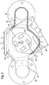
- FIGS. 1 and 2 a device according to the invention for the treatment of a liquid by loading the liquid with gas is shown.
- This information refers to an orientation of the device, as in FIG. 1 is shown.
- the device can, however, basically also be operated lying on one side.
- a space 12 for receiving a liquid In a housing 10 of the device, which may be formed of metal or plastic, there is a space 12 for receiving a liquid. In the space 12 open an inlet 14 and a drain 16, so that the liquid can flow continuously through the space 12. In the axial direction A of the inlet 14 and the outlet 16 are arranged offset to one another, in the radial direction r, they are diametrically opposite (180 ° angle) arranged.
- FIG. 3 shows an alternative embodiment of the device, in which the inlet 14 and the outlet 16 are arranged at a 120 ° angle to each other.
- a rotatably mounted mechanical Kavitationselement 18 is arranged, which is designed as a substantially disc-shaped flow body.
- the cavitation element 18 is connected via a drive shaft 20 to a continuously variable motor 22, which determines the rotational speed of the cavitation element 18.
- gas supply line 24 is arranged, which is part of a gas supply connected to a gas supply device.
- the mouth of the gas supply line 24 is directed axially on the top of the Kavitationselements 18.
- acoustic power converter 30, 32 At the inlet 14 and at the outlet 16, which extend in the radial direction, two short, angled at 90 ° connecting piece 26, 28 are arranged, to each of which an acoustic power converter 30, 32 is connected. Both acoustic power converters 30, 32 are designed as sound generators, which operate in the ultrasonic range or preferably in a lower frequency range.
- the space 12 in both embodiments has a special shape.
- the space 12 In the region of the cavitation element 18 (corresponding to the part of the space 12 which surrounds the cavitation element 18), the space 12 has a non-rotationally symmetrical cross section (radial section perpendicular to the axial direction A) deviating from the circular shape.
- the cross-section of the space 12 has a trilobular shape, which may also be referred to as a "triangle-round". Unlike a true triangle, the corners are rounded (small curve 36) and the sides are arched outwards (large curve 34).
- the trilobular shape is characterized in that, despite the triangular basic shape of the roll diameter D always remains the same, since a large rounding 34 and a small rounding 36 are always directly opposite.
- the triangular basic shape may also be a basic shape with more than three corners (in particular with four or five corners) may be provided in which the corners are rounded and the sides are curved outwards (convex). Other, irregular basic shapes with different degrees of rounding are possible. However, the triangular basic shape offers the greatest deviation from a circular shape with comparable bulges, which is desirable in terms of Kavitationsrial, as will be explained later.
- the cavitation element 18 has substantially the shape of a disc (lenticular disc) with opposite convex sides 38, 40 which meet at a sharp, circular peripheral edge 42.
- the curvature of the two sides 38, 40 may be different.
- the cavitation element 18 has a plurality of passage openings 44, which extend from the upper side 38 completely through the cavitation element 18 to the lower side 40.
- the passage openings 44 have on the top 38 and on the bottom 40 each have an elongated edge 46 and 48 like a slot.
- the edges 46 of the top 38 are not congruent with the associated edges 48 of the bottom, in particular the extension in the longitudinal direction is at the top and bottom edges 46 and 48 different sizes and / or offset. Accordingly, the perimeter of the top edges 46 may be larger, smaller, or equal to the associated bottom edges 48.
- the inner walls of the openings 44 are not straight, but rounded. This means, on the one hand, that the inner walls have a curvy profile and, on the other, that they have no edges or corners apart from the edges 46, 48. In some cases, the fillet is more pronounced - at least in sections - in the areas near the top 38 than in the areas near the bottom, in some cases it is the other way round.
- the through-openings 44 it is characteristic of the through-openings 44 that their diameter-in spite of the rounding-varies over the axial height by less than 50% and preferably by less than 30%. In the illustrated embodiment, the diameter varies significantly less than 20%.
- the passage openings 44 are also arranged so that their center is offset from the intersection of their central longitudinal axis (section lines A-A, B-B, C-C and D-D) with a radius R of the Kavitationselements 18 perpendicular to this axis in the direction of the central longitudinal axis.
- the liquid flows through the space 12 so that it is preferably completely filled with liquid.
- the cavitation element 18, which is completely immersed in the liquid, is set in such rapid rotation by the motor 22 that cavitation takes place in the liquid.
- the particular shape of the space 12 with the trilobular cross section (or a similar cross section as described above) and the particular shape of the cavitation element 18 increase the cavitation effect.
- the liquid does not completely by the rotation of the Kavitationselements 18 in an undesirable rotating circular flow, which would not be beneficial to the Kavitationsrial.
- the corners of the space 12 no "dead” places are formed in which there is little fluid exchange, since the corners are not sharp, but rounded.
- the shape of the room 12 also ensures that as few standing waves as possible are formed in room 12.
- Gas is directed in the axial direction A on top of the cavitation element 18 through the gas supply line 24.
- the gas can also be in liquid form, for. B. as liquid oxygen, are fed into the system, wherein it is preferably present in gaseous form when passing through the gas supply line 24.
- the amount of gas introduced may be, for example, 285 g / h for oxygen in well water at a temperature of 15 ° C.
- the entire space 12 is simultaneously filled by the sound waves of the acoustic power converters 30, 32 so that the bubbles generated by the Kavitationselement 18 immediately further processed by the sound energy and thereby crushed.
- cavitation with the specially shaped cavitation element 18 in the specially shaped space 12 and the additional sonication of the resulting bubbles in a comparatively low frequency range efficiently results in a mean nanometer size bubble size and produces a large proportion of bubbles in the angstrom region. This causes a large proportion of the gas introduced is dissolved molecularly dispersed in the liquid. Therefore, all of the gas introduced remains in the liquid for a relatively long time.
- suspensions can be treated very effectively by further crushing the microparticles contained therein.
- the method includes the steps of introducing the disperse liquid to be treated into the space 12 in which the rotatable cavitation element 18 is housed, rotating the cavitation element 18 to generate cavitation without treating the liquid with ultrasound, and crushing the particles in the liquid due to cavitation.
- no additional ultrasound treatment is performed in the space 12. Even before the introduction or after the removal of the suspension in or out of the space 12, this is not treated ultrasound.
- the method works without the application of ultrasound to the suspension, but exclusively with the mechanically acting cavitation element 18. On the surface of this cavitation element 18, the small cavities in the liquid form, which implode. These implosions further break up the solid particles in the liquid.
- gas can additionally be introduced into the suspension and also be dissolved in the suspension by the ultrasound-free generated cavitation.
- the dissolution of gas in the liquid phase can have advantages for the suspension and possibly cause desired chemical effects.
- An example of this is wastewater treatment.
- the method can be used in the production of liquid paint, in particular a paint, since the color pigments are particularly finely distributed here.
- the method is advantageously used in papermaking.
- the method provides, the solid particles in paper coating suspensions (eg whiting) particularly well in the Distribute liquid and crush it.
- the suspensions treated in this way are doctored onto the paper web and ensure a smooth paper surface.
- the process further disintegrates the particulates so that the germ treatment becomes much more effective.
- the simultaneous release of gas into the liquid can be used for germ killing.
Landscapes
- Chemical & Material Sciences (AREA)
- Chemical Kinetics & Catalysis (AREA)
- Organic Chemistry (AREA)
- Wood Science & Technology (AREA)
- Life Sciences & Earth Sciences (AREA)
- Engineering & Computer Science (AREA)
- Materials Engineering (AREA)
- Toxicology (AREA)
- General Health & Medical Sciences (AREA)
- Health & Medical Sciences (AREA)
- Physical Water Treatments (AREA)
- Physical Or Chemical Processes And Apparatus (AREA)
- Mixers With Rotating Receptacles And Mixers With Vibration Mechanisms (AREA)
- Mixers Of The Rotary Stirring Type (AREA)
- Cleaning By Liquid Or Steam (AREA)
Description
- Die Erfindung betrifft eine Vorrichtung zur Behandlung einer Flüssigkeit. Die Erfindung betrifft insbesondere eine Vorrichtung und ein Verfahren zum Behandeln einer Suspension.
- Das Beladen einer Flüssigkeit mit Gas ist für vielfältige Zwecke vorteilhaft. Es ermöglicht beispielsweise chemische Reaktionen zwischen dem Gas und der Flüssigkeit oder zwischen dem Gas und in der Flüssigkeit enthaltenen Stoffen. Ein möglicher Einsatzzweck findet sich in der Behandlung von Wasser, sowohl von Trinkwasser als auch von Abwasser, wo durch das Einleiten entsprechend reaktiver Gase die Keimbelastung reduziert werden kann.
- Aus der
WO 2008/080618 A1 ist eine Vorrichtung zur Behandlung einer Flüssigkeit bekannt mit einem in einem Raum angeordneten mechanischen Kavitationselement und einer Gaszufuhreinrichtung, die sich durch das Kavitationselement erstreckt. Die Vorrichtung umfasst ferner einen akustischen Leistungswandler, der Schallwellen direkt in den Raum abstrahlt. Die Bewegungen des Kavitationselements sorgen für eine Vermischung des zugeführten Gases mit der zu behandelnden Flüssigkeit, bei der die mittlere Blasengröße noch relativ groß ist. Als zweite Maßnahme werden durch den akustischen Leistungswandler gleichzeitig Schallwellen unmittelbar in die Flüssigkeit eingeleitet, wodurch die mittlere Blasengröße in der gesamten Flüssigkeit weiter reduziert wird. Um mit der bekannten Vorrichtung und dem bekannten Verfahren eine sonochemische Lösung des Gases in der Flüssigkeit zu erreichen, bei der ein überwiegender Anteil des Gases in molekular dispersiv gelöster Form vorliegt, muss der Leistungswandler als Ultraschallgeber ausgebildet sein, der Frequenzen in einem Bereich zwischen 400 und 1500 kHz, vorzugsweise zwischen 600 und 1200 kHz liefert. - Aus der Veröffentlichungsschrift
FR 2 640 328 A1 - Die Veröffentlichungsschrift
DE 3912 517 A1 , im Folgenden D2 genannt, offenbart ein Verfahren und Vorrichtung zur Förderung und Trennung der Bestandteile eines Fluids, insbesondere einer Suspension. Dabei liegt der Fokus auf der Förderung eines Schlammes oder einer verunreinigten Flüssigkeit, wobei Kavitation eingesetzt wird. Der Raum dieser Vorrichtung ist dabei kreisförmig ausgebildet. - Die Patentschrift
US 6 719 450 B2 und die VeröffentlichungUS 2002/163856 A1 beschreiben beide Handmixer, welche einen scheibenförmigen Rührer besitzen. Beide Rührer haben Bohrungen oder Aussparungen, welche von der Oberseite des scheibenförmigen Rührers auf dessen Unterseite reichen. - Dokument
US2006/0176768 beschreibt eine Vorrichtung zur Behandlung einer Flüssigkeit, mit einem Raum, einem im Raum angeordneten drehbaren Kavitationselement, wobei der Raum im Bereich des Kavitationselements einen Querschnitt mit unterschiedlichen Rundungen hat, wobei der Querschnitt des Raums eine Grundform eines Polygons mit abgerundeten Ecken aufweist. - Aufgabe der Erfindung ist es, das Beladen einer Flüssigkeit mit Gas noch effizienter zu gestalten.
- Gelöst wird diese Aufgabe durch eine Vorrichtung mit den Merkmalen des Anspruchs 1 und durch ein Verfahren mit den Merkmalen des Anspruchs 13. Vorteilhafte und zweckmäßige Ausgestaltungen der erfindungsgemäßen Vorrichtung sind in den Unteransprüchen angegeben.
- Gemäß einem ersten Aspekt umfasst die erfindungsgemäße Vorrichtung zur Behandlung einer Flüssigkeit einen Raum und ein im Raum angeordnetes drehbares Kavitationselement, insbesondere in Form eines Strömungskörpers. Der Raum hat im Bereich des Kavitationselements einen Querschnitt mit unterschiedlichen Rundungen.
- Dieser Aspekt der Erfindung beruht auf der Erkenntnis, dass ein Querschnitt mit unterschiedlichen Rundungen einerseits einer unerwünschten Rotationsströmung der Flüssigkeit um die Drehachse des Kavitationselements entgegenwirkt, andererseits aber "tote" Raumecken vermeidet, in denen nur wenig Flüssigkeitsaustausch stattfindet. Die erfindungsgemäße Querschnittform des Raums unterstützt vielmehr die Bildung lokaler Verwirbelungen mit hohen Strömungsgeschwindigkeiten, was die Kavitationswirkung deutlich erhöht.
- Vorzugsweise weist der Querschnitt des Raums eine Grundform eines Polygons mit abgerundeten Ecken auf. Durch die abgerundeten Ecken wird ein Flüssigkeitsstau in den Ecken effektiv vermieden.
- Zur Vermeidung "stiller Buchten" im Raum sind die Seiten der polygonen Grundform bevorzugt konvex.
- Allgemein ist eine Gestaltung des Raums vorteilhaft, bei dem die Grundform des Raumquerschnitts die eines regelmäßigen Polygons ist.
- Als besonders vorteilhaft erweist sich ein Raum, dessen Querschnitt eine trilobulare Form hat. Eine solche Form weicht deutlich von einer Kreisform ab, die eine unerwünschte Rotationsströmung begünstigen würde, weist aber dennoch Wandabschnitte auf, die annähernd tangential zu einem allgemein kreisscheibenförmigen Kavitationselement verlaufen.
- Grundsätzlich können aber auch Querschnitte des Raums vorteilhaft sein, deren Grundform die eines unregelmäßigen Polygons ist.
- Gemäß einem zweiten Aspekt umfasst die erfindungsgemäße Vorrichtung zur Behandlung einer Flüssigkeit einen Raum und ein im Raum angeordnetes, im Wesentlichen scheibenförmiges Kavitationselement. Das Kavitationselement weist (vorzugsweise längliche) Durchtrittsöffnungen auf, deren Innenwände verrundet sind.
- Dieser Aspekt der Erfindung beruht auf der Erkenntnis, dass eine solche Form der Durchtrittsöffnungen bei schneller Drehung des Kavitationselements eine optimale Beschleunigung der Flüssigkeit ermöglicht, ohne dass es zu einem unerwünschten Aufscheren der Flüssigkeit kommt.
- Bei einer bevorzugten Ausführungsform der Erfindung erstrecken sich die Durchtrittsöffnungen jeweils von einer Oberseite vollständig durch das Kavitationselement hindurch zu einer Unterseite. Dies erlaubt grundsätzlich einen begrenzten Durchtritt der Flüssigkeit durch das Kavitationselement.
- Eine bevorzugte Gestaltung der Durchtrittsöffnungen sieht vor, dass der Durchmesser der Durchtrittsöffnungen über deren axiale Höhe um weniger als 50%, vorzugsweise um weniger als 30%, weiter vorzugsweise um weniger als 20% variiert. Dadurch ist sichergestellt, dass sich keine Flüssigkeit in den Durchtrittsöffnungen sammelt.
- Gemäß einer besonders bevorzugten Gestaltung der Durchtrittsöffnungen sind die Innenwände in Bereichen nahe der Oberseite und in Bereichen nahe der Unterseite unterschiedlich stark verrundet. Die Verrundungen können insbesondere so auf die Form des Kavitationselements abgestimmt werden, dass sich ein für die angestrebten Druckschwankungen günstiges Gesamtströmungsverhalten einstellt.
- Die Durchtrittsöffnungen können auf der Oberseite und auf der Unterseite jeweils einen länglichen Rand wie ein Langloch haben.
- Eine weitere bevorzugte Ausführungsform sieht vor, dass in Draufsicht der Rand der Durchtrittsöffnung auf der Oberseite mit dem zugehörigen Rand der Durchtrittsöffnung auf der Unterseite nicht deckungsgleich ist.
- Insbesondere kann die Erstreckung des Rands auf der Oberseite und des Rands auf der Unterseite in Längsrichtung der Durchtrittsöffnung unterschiedlich groß und/oder versetzt sein.
- In Verbindung mit den Verrundungen kann der Kavitationseffekt durch eine Anordnung der Durchtrittsöffnungen weiter optimiert werden, bei der jeweils der Mittelpunkt der Durchtrittsöffnung gegenüber dem Schnittpunkt ihrer mittleren Längsachse mit einem zu dieser Achse senkrechten Radius des Kavitationselements in Richtung der mittleren Längsachse versetzt ist.
- Für die Behandlung von Wasser, insbesondere von Trinkwasser, ist eine Vorrichtung vorteilhaft, bei der der Raum in einem Gehäuse aus Kunststoff angeordnet ist. Ein Kunststoffgehäuse bietet gegenüber einem Metallgehäuse den Vorteil, dass es besser zu reinigen ist und nicht von Desinfektionsmittel angegriffen wird. Eine Zugabe von Elektrolyten zur Flüssigkeit ist ebenfalls ohne Probleme möglich.
- Insbesondere in Kombination mit einem trilobularen Querschnitt des Raumes, in den ein Zulauf und ein Ablauf für die Flüssigkeit münden, ist eine Anordnung günstig, bei der der Zulauf und der Ablauf in einer radialen Richtung in einem Winkel von weniger als 180°, vorzugsweise in einem Winkel von etwa 120° zueinander angeordnet sind.
- Hinsichtlich der Zufuhr eines Gases in die Flüssigkeit ist eine Gaszufuhrleitung bevorzugt, deren Mündung axial auf eine Oberseite des Kavitationselements gerichtet ist, vorzugsweise nahe der Drehachse des Kavitationselements.
- Insbesondere kann die Gaszufuhrleitung zumindest abschnittsweise parallel zu einer Antriebswelle verlaufen, auf der das Kavitationselement angeordnet ist.
- Eine Kosteneinsparung bei der Realisierung der erfindungsgemäßen Vorrichtung ergibt sich durch die Verwendung wenigstens eines akustischen Leistungswandlers, der so angeordnet ist, dass er Schallwellen direkt in den Raum abstrahlt, wobei die Frequenz der Schallwellen unterhalb des Ultraschallfrequenzbereichs liegt. Es hat sich gezeigt, dass im Vergleich zu der eingangs erwähnten, aus dem Stand der Technik bekannten Vorrichtung eine geringere Leistung des akustischen Leistungswandlers ausreicht, um eine gewünschte Bläschengröße zu erzielen.
- Allgemein ist es mit den erfindungsgemäßen Maßnahmen möglich, einen sehr hohen Anteil an Gas in die Flüssigkeit einzubringen. Die erfindungsgemäße Vorrichtung eignet sich damit bestens zur Reinigung von Wasser, insbesondere von Trink- oder Abwasser. Sie ist insbesondere bei Zufuhr von Ozon, das sich molekular dispers in der Flüssigkeit lösen lässt, zum Entkeimen der Flüssigkeit oder generell zum Zerstören von Bakterien, Viren, Pilzsporen, Toxinen oder endokrinen Stoffen oder zum Denaturieren von Proteinen einsetzbar. Darüber hinaus lässt sich die Vorrichtung allgemein zur Gasbeladung von Flüssigkeiten, nicht nur von Wasser oder Abwasser, mit jedem geeigneten Gas verwenden.
- Die Erfindung betrifft ferner ein Verfahren zum Behandeln einer Suspension, insbesondere mittels einer erfindungsgemäßen Vorrichtung, gekennzeichnet durch folgende Schritte:
- Einleiten der zu behandelnden, dispersen Flüssigkeit in einen Raum, in welchem ein sich drehendes Kavitationselement untergebracht ist,
- Drehen des Kavitationselements bis zur Erzeugung von Kavitation ohne Behandlung der Flüssigkeit mit Ultraschall, und
Zerkleinern der Teilchen in der Flüssigkeit durch die Kavitation. - Das erfindungsgemäße Verfahren arbeitet ohne die Beaufschlagung der Suspension mit Ultraschall, sondern ausschließlich mit dem mechanisch wirkenden Kavitationselement. An der Oberfläche dieses Kavitationselements bilden sich die kleinen Hohlräume in der Flüssigkeit, die implodieren. Durch dieses Implodieren werden die sich in der Flüssigkeit befindlichen Feststoffteilchen weiter zerkleinert. Das Zerkleinern der Teilchen erfolgt also nicht (nur) durch Auftreffen der Teilchen auf das Kavitationselement, sondern durch die frei werdende Energie bei den zahlreichen Implosionen an der Oberfläche des Kavitationselements.
- Wenn Gas in die Suspension eingeleitet und ebenfalls durch die ultraschallfrei erzeugte Kavitation in der Suspension gelöst wird, wird gleichzeitig die Kavitation reduziert. Das Lösen von Gas in der flüssigen Phase kann Vorteile für die Suspension haben und gegebenenfalls gewünschte chemische Effekte hervorrufen. Ein Beispiel hierfür ist die Abwasserbehandlung.
- Das erfindungsgemäße Verfahren wird besondere Vorteile bei der Herstellung von flüssiger Farbe, insbesondere eines Lackes, bringen, da hier die Farbpigmente besonders fein verteilt werden. Ferner ist das Verfahren vorteilhaft bei der Behandlung von Papierbeschichtungssuspensionen (z.B. Schlämmkreide) einsetzbar sowie beim Behandeln von Abwasser. Bezüglich der Abwasserbehandlung ist zu ergänzen, dass sich Keime im Schatten von Feststoffteilchen im Abwasser besonders gut halten können. Eine UV-Lichtbehandlung ist deshalb nur als unterstützende Maßnahme zu sehen. Wenn jedoch, wie durch die Erfindung gelehrt, die Feststoffteilchen noch weiter zerkleinert werden, ist die Keimbehandlung wesentlich wirkungsvoller. Das gleichzeitige Lösen von Gas in die Flüssigkeit kann zur Keimabtötung eingesetzt werden.
- Weitere Merkmale und Vorteile der Erfindung ergeben sich aus der nachfolgenden Beschreibung und aus den beigefügten Zeichnungen, auf die Bezug genommen wird. In den Zeichnungen zeigen:
-
Figur 1 eine Seitenansicht einer erfindungsgemäßen Vorrichtung zur Durchführung es erfindungsgemäßen Verfahrens; -
Figur 2 eine teilgeschnittene Draufsicht auf die Vorrichtung inFigur 1 ; -
Figur 3 eine teilgeschnittene Draufsicht auf eine erfindungsgemäße Vorrichtung nach einer alternativen Ausführungsform, mit der ebenfalls das erfindungsgemäße Verfahren ausführbar ist; -
Figur 4 eine Draufsicht auf ein mechanisches Kavitationselement einer erfindungsgemäßen Vorrichtung; -
Figur 5 eine Schnittansicht entlang der Schnittlinie A-A inFigur 4 ; -
Figur 6 eine Schnittansicht entlang der Schnittlinie B-B inFigur 4 ; -
Figur 7 eine Schnittansicht entlang der Schnittlinie C-C inFigur 4 ; und -
Figur 8 eine Schnittansicht entlang der Schnittlinie D-D inFigur 4 . - In den
Figuren 1 und2 ist eine erfindungsgemäße Vorrichtung zur Behandlung einer Flüssigkeit durch Beladen der Flüssigkeit mit Gas gezeigt. In der nachfolgenden Beschreibung werden zur Erleichterung des Verständnisses Angaben wie oben, unten, etc. verwendet. Diese Angaben beziehen sich auf eine Orientierung der Vorrichtung, wie sie inFigur 1 dargestellt ist. Die Vorrichtung kann aber grundsätzlich auch auf einer Seite liegend betrieben werden. - Der grundlegende Aufbau und die grundlegende Funktionsweise einer solchen Vorrichtung sind dem Fachmann bekannt, insbesondere aus der
WO 2008/080618 A1 , sodass hier vornehmlich auf die Besonderheiten der erfindungsgemäßen Vorrichtung eingegangen wird. - In einem Gehäuse 10 der Vorrichtung, das aus Metall oder Kunststoff gebildet sein kann, befindet sich ein Raum 12 zur Aufnahme einer Flüssigkeit. In den Raum 12 münden ein Zulauf 14 und ein Ablauf 16, sodass die Flüssigkeit kontinuierlich durch den Raum 12 strömen kann. In axialer Richtung A sind der Zulauf 14 und der Ablauf 16 versetzt zueinander angeordnet, in radialer Richtung r sind sie diametral gegenüberliegend (180°-Winkel) angeordnet.
-
Figur 3 zeigt eine alternative Ausführungsform der Vorrichtung, bei der der Zulauf 14 und der Ablauf 16 in einem 120°-Winkel zueinander angeordnet sind. - Zentral im Raum 12 ist ein drehbar gelagertes mechanisches Kavitationselement 18 angeordnet, das als im Wesentlichen diskusförmiger Strömungskörper ausgebildet ist. Das Kavitationselement 18 ist über eine Antriebswelle 20 mit einem stufenlos regelbaren Motor 22 verbunden, der die Drehgeschwindigkeit des Kavitationselements 18 bestimmt.
- Neben der Antriebswelle 20 ist eine parallel zu dieser in den Raum 12 mündende Gaszufuhrleitung 24 angeordnet, die Teil einer an eine Gasversorgung angeschlossenen Gaszufuhreinrichtung ist. Die Mündung der Gaszufuhrleitung 24 ist axial auf die Oberseite des Kavitationselements 18 gerichtet.
- Am Zulauf 14 und am Ablauf 16, die sich in radialer Richtung erstrecken, sind zwei kurze, um 90° abgewinkelte Verbindungsstutzen 26, 28 angeordnet, an die jeweils ein akustischer Leistungswandler 30, 32 angeschlossen ist. Beide akustischen Leistungswandler 30, 32 sind als Schallgeber ausgebildet, die im Ultraschallbereich oder vorzugsweise in einem niedrigeren Frequenzbereich arbeiten.
- Wie aus den
Figuren 2 und3 hervorgeht, weist der Raum 12 bei beiden Ausführungsformen eine besondere Gestalt auf. Der Raum 12 hat im Bereich des Kavitationselements 18 (entsprechend dem Teil des Raums 12, der das Kavitationselement 18 umgibt) einen von der Kreisform abweichenden, nicht rotationssymmetrischen Querschnitt (radialer Schnitt senkrecht zur Axialrichtung A). - In den dargestellten Ausführungsformen hat der Querschnitt des Raums 12 eine trilobulare Form, die man auch als "Dreieck-Rund" bezeichnen kann. Anders als bei einem echten Dreieck sind die Ecken abgerundet (kleine Rundung 36), und die Seiten sind nach außen gewölbt (große Rundung 34). Die trilobulare Form ist dadurch charakterisiert, dass trotz der dreieckig ausgerichteten Grundform der Rolldurchmesser D immer gleich bleibt, da sich eine große Rundung 34 und eine kleine Rundung 36 immer direkt gegenüber stehen.
- Anstelle der dreieckigen Grundform kann auch eine Grundform mit mehr als drei Ecken (insbesondere mit vier oder fünf Ecken) vorgesehen sein, bei der die Ecken abgerundet und die Seiten nach außen gewölbt (konvex) sind. Auch andere, unregelmäßige Grundformen mit unterschiedlich stark ausgeprägten Rundungen sind möglich. Die dreieckige Grundform bietet jedoch bei vergleichbaren Wölbungen die größte Abweichung von einer Kreisform, was hinsichtlich der Kavitationswirkung erwünscht ist, wie später noch erläutert wird.
- In
Figur 4 ist das im Raum 12 drehbar angeordnete Kavitationselement 18 separat dargestellt. Das Kavitationselement 18 hat im Wesentlichen die Form eines Diskus (linsenförmige Scheibe) mit entgegengesetzten konvexen Seiten 38, 40, die an einem scharfen, kreisförmigen Umfangsrand 42 aufeinandertreffen. Die Krümmung der beiden Seiten 38, 40 kann unterschiedlich sein. - Das Kavitationselement 18 weist mehrere Durchtrittsöffnungen 44 auf, die sich von der Oberseite 38 vollständig durch das Kavitationselement 18 hindurch zur Unterseite 40 erstrecken. Die Durchtrittsöffnungen 44 haben auf der Oberseite 38 und auf der Unterseite 40 jeweils einen länglichen Rand 46 bzw. 48 wie ein Langloch. Jedoch sind in Draufsicht die Ränder 46 der Oberseite 38 mit den zugehörigen Rändern 48 der Unterseite nicht deckungsgleich, insbesondere die Erstreckung in Längsrichtung ist bei den oberseitigen und unterseitigen Rändern 46 bzw. 48 unterschiedlich groß und/oder versetzt. Dementsprechend kann der Umfang der oberseitigen Ränder 46 im Vergleich zu den zugehörigen unterseitigen Rändern 48 größer, kleiner oder gleich groß sein.
- Wie aus den Schnittansichten der
Figuren 5 bis 8 hervorgeht, sind die Innenwände der Durchtrittsöffnungen 44 nicht gerade, sondern verrundet. Das bedeutet zum einen, dass die Innenwände ein kurviges Profil haben, und zum anderen, dass sie - abgesehen von den Rändern 46, 48 - keine Kanten oder Ecken haben. In einigen Fällen ist die Verrundung - zumindest abschnittsweise - in den Bereichen nahe der Oberseite 38 stärker ausgeprägt als in den Bereichen nahe der Unterseite, in einigen Fällen ist es umgekehrt. - Ferner ist für die Durchtrittsöffnungen 44 charakteristisch, dass ihr Durchmesser - trotz der Verrundungen - über die axiale Höhe um weniger als 50% und vorzugsweise um weniger als 30% variiert. Im dargestellten Ausführungsbeispiel variiert der Durchmesser um deutlich weniger als 20%.
- Die Durchtrittsöffnungen 44 sind außerdem so angeordnet, dass ihr Mittelpunkt gegenüber dem Schnittpunkt ihrer mittleren Längsachse (Schnittlinien A-A, B-B, C-C bzw. D-D) mit einem zu dieser Achse senkrechten Radius R des Kavitationselements 18 in Richtung der mittleren Längsachse versetzt ist.
- Zur Gasbeladung einer Flüssigkeit mit der Vorrichtung durchströmt die Flüssigkeit den Raum 12 so, dass dieser vorzugsweise vollständig mit Flüssigkeit ausgefüllt ist. Das vollständig in die Flüssigkeit eingetauchte Kavitationselement 18 wird durch den Motor 22 in so schnelle Rotation versetzt, dass es in der Flüssigkeit zur Kavitation kommt.
- Dabei sorgen die besondere Form des Raums 12 mit dem trilobularen Querschnitt (oder einem ähnlichen Querschnitt wie oben beschrieben) und die besondere Form des Kavitationselements 18 für eine Erhöhung der Kavitationswirkung.
- Aufgrund der Querschnittform des Raums 12 mit den unterschiedlichen Rundungen 34, 36 gerät die Flüssigkeit durch die Drehung des Kavitationselements 18 nicht vollständig in eine unerwünschte rotierende Kreisströmung, die der Kavitationswirkung nicht zuträglich wäre. In den Ecken des Raums 12 bilden sich aber keine "toten" Stellen, in denen nur wenig Flüssigkeitsaustausch stattfindet, da die Ecken nicht scharf, sondern abgerundet sind. Die Form des Raums 12 sorgt auch dafür, dass sich möglichst wenige stehende Wellen im Raum 12 ausbilden.
- Aufgrund der verrundeten Durchtrittsöffnungen 44 im Kavitationselement 18 bilden sich sehr hohe Strömungsgeschwindigkeiten nicht nur im Bereich des Umfangsrands des Kavitationselements 18, sondern auch im Bereich der Durchtrittsöffnungen 44 aus, wodurch gerade an diesen Stellen eine sehr hohe Kavitationswirkung resultiert. Die Durchtrittsöffnungen 44 wirken aber auch insbesondere bei hohen Drehzahlen des Kavitationselements 18 effektiv einer unerwünschten Aufscherung der Flüssigkeit entgegen.
- Durch die besondere Form des Raumquerschnitts mit den unterschiedlichen Rundungen 34, 36 und die besondere Form der Durchtrittsöffnungen 44 des Kavitationselements 18 wird insgesamt eine unerwünschte Pumpenwirkung des Kavitationselements 18 auf die Flüssigkeit vermieden.
- Durch die Gaszufuhrleitung 24 wird Gas in axialer Richtung A auf die Oberseite des Kavitationselements 18 geleitet. Das Gas kann auch in flüssiger Form, z. B. als flüssiger Sauerstoff, in das System eingespeist werden, wobei es bei Durchtritt durch die Gaszufuhrleitung 24 vorzugsweise bereits gasförmig vorliegt.
- Aufgrund der hohen Kavitationswirkung wird das eingeleitete Gas praktisch vollständig in die Flüssigkeit eingebracht. Die eingeleitete Gasmenge kann beispielsweise 285 g/h für Sauerstoff in Brunnenwasser mit einer Temperatur von 15°C betragen.
- Der gesamte Raum 12 wird gleichzeitig von den Schallwellen der akustischen Leistungswandler 30, 32 erfüllt sodass die durch das Kavitationselement 18 erzeugten Blasen sofort durch die Schallenergie weiterbearbeitet und dabei zerkleinert werden.
- Insgesamt resultiert durch die Kavitation mithilfe des besonders geformten Kavitationselements 18 in dem besonders geformten Raum 12 und die zusätzliche Schallbehandlung der entstandenen Blasen in einem vergleichsweise niedrigen Frequenzbereich auf effiziente Weise eine mittlere Blasengröße im Nanometerbereich, und es wird ein großer Anteil von Blasen im Angströmbereich erzeugt. Dies führt dazu, dass ein großer Anteil des eingeleiteten Gases molekular dispers in der Flüssigkeit gelöst wird. Daher verbleibt das gesamte eingebrachte Gas über einen relativ langen Zeitraum in der Flüssigkeit.
- Die Erfindung wurde anhand bevorzugter Ausführungsformen beschrieben. Selbstverständlich sind Abwandlungen und Ergänzungen im Ermessen des Fachmanns möglich, ohne dass dadurch der Erfindungsgedanke verlassen wird.
- Mit der zuvor genannten Vorrichtung lassen sich Suspensionen sehr effektiv behandeln, indem die sich darin befindlichen Kleinstteilchen weiter zerkleinern lassen. Das Verfahren sieht folgende Schritte vor: Einleiten der zu behandelnden, dispersen Flüssigkeit in den Raum 12, in welchem das in Rotation versetzbare Kavitationselement 18 untergebracht ist, Drehen des Kavitationselements 18 bis zur Erzeugung von Kavitation ohne Behandlung der Flüssigkeit mit Ultraschall, und Zerkleinern der Teilchen in der Flüssigkeit durch die Kavitation. Bei diesem Verfahren wird im Raum 12 keine zusätzliche Ultraschallbehandlung durchgeführt. Auch vor dem Einleiten oder nach dem Entfernen der Suspension in bzw. aus dem Raum 12 wird diese nicht Ultraschall behandelt.
- Das Verfahren arbeitet ohne die Beaufschlagung der Suspension mit Ultraschall, sondern ausschließlich mit dem mechanisch wirkenden Kavitationselement 18. An der Oberfläche dieses Kavitationselements 18 bilden sich die kleinen Hohlräume in der Flüssigkeit, die implodieren. Durch diese Implosionen werden die sich in der Flüssigkeit befindlichen Feststoffteilchen weiter zerkleinert.
- Alternativ kann zusätzlich Gas in die Suspension eingeleitet und ebenfalls durch die ultraschallfrei erzeugte Kavitation in der Suspension gelöst werden. Das Lösen von Gas in der flüssigen Phase kann Vorteile für die Suspension haben und gegebenenfalls gewünschte chemische Effekte hervorrufen. Ein Beispiel hierfür ist die Abwasserbehandlung.
- Das Verfahren kann bei der Herstellung von flüssiger Farbe, insbesondere eines Lackes, eingesetzt werden, da hier die Farbpigmente besonders fein verteilt werden.
- Ferner ist das Verfahren vorteilhaft bei Papierherstellung eingesetzt werden. Das Verfahren sieht vor, die Feststoffteilchen in von Papierbeschichtungssuspensionen (z.B. Schlämmkreide) besonders gut in der Flüssigkeit zu verteilen und zu zerkleinern. Die so behandelten Suspensionen werden auf die Papierbahn aufgerakelt und sorgen für eine glatte Papieroberfläche.
- Beim Behandeln von Abwasserwerden durch das Verfahren die Feststoffteilchen noch weiter zerkleinert, so dass die Keimbehandlung wesentlich wirkungsvoller wird. Das gleichzeitige Lösen von Gas in die Flüssigkeit kann zur Keimabtötung eingesetzt werden.
-
- 10
- Gehäuse
- 12
- Raum
- 14
- Zulauf
- 16
- Ablauf
- 18
- Kavitationselement
- 20
- Antriebswelle
- 22
- Motor
- 24
- Gaszufuhrleitung
- 26
- erster Verbindungsstutzen
- 28
- zweiter Verbindungsstutzen
- 30
- erster akustischer Leistungswandler
- 32
- zweiter akustischer Leistungswandler
- 34
- große Rundung
- 36
- kleine Rundung
- 38
- Oberseite des Kavitationselements
- 40
- Unterseite des Kavitationselements
- 42
- Umfangsrand
- 44
- Durchtrittsöffnungen
- 46
- oberseitige Ränder
- 48
- unterseitige Ränder
Claims (15)
- Vorrichtung zur Behandlung einer Flüssigkeit, mit- einem Raum (12),- einem im Raum (12) angeordneten, im Wesentlichen scheibenförmigen Kavitationselement (18),dadurch gekennzeichnet, dass das Kavitationselement (18) längliche Durchtrittsöffnungen (44) aufweist, deren Innenwände verrundet sind, wobei die Innenwände der Durchtrittsöffnungen (44) - in einer entlang der jeweiligen Durchtrittsöffnung (44) von der Oberseite (38) bis zu der Unterseite (40) des Kavitatationselementes (18) verlaufenden Schnittebene (A-A, B-B, C-C, D-D) betrachtet - kurvige Profile haben und abgesehen von den Rändern (44, 46) keine Kanten oder Ecken haben.
- Vorrichtung nach Anspruch 1, dadurch gekennzeichnet, dass sich die Durchtrittsöffnungen (44) jeweils von einer Oberseite (38) vollständig durch das Kavitationselement (18) hindurch zu einer Unterseite (40) erstrecken, wobei der Durchmesser der Durchtrittsöffnungen (44) über deren axiale Höhe um weniger als 50%, vorzugsweise um weniger als 30%, weiter vorzugsweise um weniger als 20% variiert.
- Vorrichtung nach Anspruch 1, dadurch gekennzeichnet, dass die Innenwände in Bereichen nahe der Oberseite (38) und in Bereichen nahe der Unterseite (40) unterschiedlich stark verrundet sind und/oder dass die Durchtrittsöffnungen (44) auf der Oberseite (38) und auf der Unterseite (40) jeweils einen länglichen Rand (46, 48) wie ein Langloch haben.
- Vorrichtung nach einem der Ansprüche 1 oder 2 dadurch gekennzeichnet, dass in Draufsicht der Rand (46) der Durchtrittsöffnung (44) auf der Oberseite (38) mit dem zugehörigen Rand (48) der Durchtrittsöffnung (44) auf der Unterseite (40) nicht deckungsgleich ist, wobei vorzugsweise die Erstreckung des Rands (46) auf 10 der Oberseite (38) und des Rands (48) auf der Unterseite (40) in Längsrichtung der Durchtrittsöffnung (44) unterschiedlich groß und/oder versetzt ist.
- Vorrichtung nach einem der Ansprüche 1 bis 4, dadurch gekennzeichnet, dass die Durchtrittsöffnungen (44) so angeordnet sind, dass ihr Mittelpunkt gegenüber dem Schnittpunkt ihrer mittleren Längsachse mit einem zu dieser Achse senkrechten Radius R des Kavitationselements (18) in Richtung der mittleren Längsachse versetzt ist.
- Vorrichtung zur Behandlung einer Flüssigkeit nach Anspruch 1, dadurch gekennzeichnet, dass der Raum (12) im Bereich des Kavitationselements (18) einen Querschnitt mit unterschiedlichen Rundungen (34, 36) hat und dass der Querschnitt des Raums (12) eine Grundform eines Polygons mit abgerundeten Ecken aufweist.
- Vorrichtung nach Anspruch 6, dadurch gekennzeichnet, dass die Seiten der polygonen Grundform konvex sind.
- Vorrichtung nach Anspruch 7, dadurch gekennzeichnet, dass die Grundform des Querschnitts die eines regelmäßigen Polygons ist, wobei der Querschnitt des Raums (12) eine trilobulare Form hat.
- Vorrichtung nach einem der Ansprüche 6 oder 7, dadurch gekennzeichnet, dass die Grundform des Querschnitts die eines unregelmäßigen Polygons ist.
- Vorrichtung nach einem der Ansprüche 6 bis 9, dadurch gekennzeichnet, dass in den Raum (12) ein Zulauf (14) und ein Ablauf (16) münden, die in einer radialen Richtung r in einem Winkel von weniger als 180°, vorzugsweise in einem Winkel von etwa 120° zueinander angeordnet sind.
- Vorrichtung nach einem der Ansprüche 6 bis 10, gekennzeichnet durch eine Gaszufuhrleitung (24), deren Mündung axial auf eine Oberseite des Kavitationselements (18) gerichtet ist, vorzugsweise nahe der Drehachse des Kavitationselements (18), wobei insbesondere die Gaszufuhrleitung (24) zumindest abschnittsweise parallel zu einer Antriebswelle (20) verläuft, auf der das Kavitationselement (18) angeordnet ist.
- Vorrichtung nach einem der Ansprüche 6 bis 11, gekennzeichnet durch wenigstens einen akustischen Leistungswandler (30, 32), der so angeordnet ist, dass er Schallwellen direkt in den Raum (12) abstrahlt, wobei die Frequenz der Schallwellen unterhalb des Ultraschallfrequenzbereichs liegt.
- Verfahren zum Behandeln einer Suspension, mittels einer Vorrichtung nach einem der vorhergehenden Ansprüche, gekennzeichnet durch folgende Schritte:a) Einleiten der zu behandelnden, dispersen Flüssigkeit in einen Raum, in welchem ein sich drehendes Kavitationselement untergebracht ist,b) Drehen des Kavitationselements bis zur Erzeugung von Kavitation ohne Behandlung der Flüssigkeit mit Ultraschall, undc) Zerkleinern der Teilchen in der Flüssigkeit durch die Kavitation.
- Verfahren nach Anspruch 13, dadurch gekennzeichnet, dass Gas in die Suspension eingeleitet und durch die ultraschallfrei erzeugte Kavitation in der Suspension gelöst wird.
- Verfahren nach Anspruch 13 oder 14, dadurch gekennzeichnet, dass das Verfahren ein Verfahren zum Herstellen von flüssiger Farbe, insbesondere eines Lackes, ein Verfahren zur Behandlung einer Schlämmkreide für die Papieroberflächenbeschichtung oder ein Verfahren zum Behandeln von Abwasser ist.
Applications Claiming Priority (2)
| Application Number | Priority Date | Filing Date | Title |
|---|---|---|---|
| DE102010047947A DE102010047947A1 (de) | 2010-10-08 | 2010-10-08 | Vorrichtung zur Behandlung einer Flüssigkeit und Verfahren zum Behandeln einer Suspension |
| PCT/EP2011/005022 WO2012045470A1 (de) | 2010-10-08 | 2011-10-07 | Vorrichtung zur behandlung einer flüssigkeit und verfahren zum behandeln einer suspension |
Publications (2)
| Publication Number | Publication Date |
|---|---|
| EP2624943A1 EP2624943A1 (de) | 2013-08-14 |
| EP2624943B1 true EP2624943B1 (de) | 2016-12-21 |
Family
ID=44785810
Family Applications (1)
| Application Number | Title | Priority Date | Filing Date |
|---|---|---|---|
| EP11767637.9A Not-in-force EP2624943B1 (de) | 2010-10-08 | 2011-10-07 | Vorrichtung zur behandlung einer flüssigkeit und verfahren zum behandeln einer suspension |
Country Status (14)
| Country | Link |
|---|---|
| US (1) | US20140007793A1 (de) |
| EP (1) | EP2624943B1 (de) |
| JP (1) | JP6077448B2 (de) |
| KR (1) | KR20130133182A (de) |
| CN (1) | CN103189133B (de) |
| AU (1) | AU2011313585B2 (de) |
| BR (1) | BR112013007996A2 (de) |
| CA (1) | CA2812354A1 (de) |
| DE (1) | DE102010047947A1 (de) |
| IL (1) | IL225608A0 (de) |
| MA (1) | MA34871B1 (de) |
| MX (1) | MX2013003465A (de) |
| WO (1) | WO2012045470A1 (de) |
| ZA (1) | ZA201302353B (de) |
Cited By (1)
| Publication number | Priority date | Publication date | Assignee | Title |
|---|---|---|---|---|
| DE202024102969U1 (de) | 2024-06-05 | 2024-12-16 | USONiQ Technologies GmbH | Aufreinigung einer bromidbelasteten Flüssigkeit durch erweiterte Oxidation (AOP) |
Families Citing this family (2)
| Publication number | Priority date | Publication date | Assignee | Title |
|---|---|---|---|---|
| FI127076B (en) | 2016-04-14 | 2017-10-31 | Nofa Oy | A cavitation arrangement for removing harmful material from the fluid |
| DE102024115728A1 (de) * | 2024-06-05 | 2025-12-11 | USONiQ Technologies GmbH | Aufreinigung einer bromidbelasteten Flüssigkeit durch erweiterte Oxidation (AOP) |
Citations (3)
| Publication number | Priority date | Publication date | Assignee | Title |
|---|---|---|---|---|
| US20020163856A1 (en) * | 2001-05-04 | 2002-11-07 | D'agostino William | Impeller and shield for mixing apparatus |
| US6719450B2 (en) * | 2002-04-19 | 2004-04-13 | Bonjour, Incorporated | Processing tool attachments for a food mixing device |
| US20060176768A1 (en) * | 2005-02-04 | 2006-08-10 | Williams Brian P | Blender Jar |
Family Cites Families (19)
| Publication number | Priority date | Publication date | Assignee | Title |
|---|---|---|---|---|
| FR1192486A (fr) * | 1957-12-27 | 1959-10-27 | Blanchisserie Du Bois De Boulo | Machine à homogénéiser les liquides |
| GB1041935A (en) * | 1964-08-31 | 1966-09-07 | Miklos Patay | Improvements in centrifugal pumps |
| JPS5021682B1 (de) * | 1968-04-05 | 1975-07-24 | ||
| JPS56500384A (de) * | 1979-03-27 | 1981-03-26 | ||
| FR2640328B1 (fr) * | 1988-12-09 | 1991-03-15 | Schlumberger Cie Dowell | Rotor a pales pour pompe du type centrifuge, pompe et melangeur en faisant application |
| DE3912517C2 (de) * | 1989-04-17 | 1997-02-20 | Kupczik Guenter | Verfahren und Vorrichtung zur Förderung und Trennung der Bestandteile eines Fluids, insbesondere einer Suspension, unter Aufschluß verklammerter Teilchen |
| JPH0354742U (de) * | 1989-09-26 | 1991-05-27 | ||
| JPH04161296A (ja) * | 1990-10-25 | 1992-06-04 | Sanbio:Kk | 気泡発生装置 |
| DE4223434C1 (de) * | 1992-07-16 | 1993-11-18 | Ppv Verwaltungs Ag Zuerich | Scheibenförmiges Mischwerkzeug |
| US6491829B2 (en) * | 1999-12-24 | 2002-12-10 | Takashi Nishimoto | Method and unit for processing contaminated liquid |
| JP3762206B2 (ja) * | 2000-09-13 | 2006-04-05 | 株式会社アスプ | 超微細気泡発生装置 |
| US7316502B2 (en) * | 2005-04-13 | 2008-01-08 | Richard Freeman | Mixing blade, blending apparatus, and method of mixing |
| US7718405B2 (en) * | 2005-09-19 | 2010-05-18 | American Air Liquide, Inc. | Use of pure oxygen in viscous fermentation processes |
| JP5133556B2 (ja) * | 2006-12-07 | 2013-01-30 | 株式会社横田製作所 | 微細気泡発生装置 |
| DE102007013533A1 (de) * | 2006-12-28 | 2008-07-03 | Ultrasonic Systems Gmbh | Ultraschall gestütztes Verfahren und Vorrichtung zur Gasbeladung und Entkeimung von durch Keime kontaminierten Flüssigkeiten und Kläranlagen |
| JP2009150223A (ja) * | 2007-12-18 | 2009-07-09 | Aisin Seiki Co Ltd | 流体ポンプ |
| JP2010031808A (ja) * | 2008-07-30 | 2010-02-12 | Shinmaywa Industries Ltd | ポンプ用ケーシング及びそれを備えたポンプ |
| JP2009082923A (ja) * | 2009-01-26 | 2009-04-23 | Jfe Engineering Kk | 気泡発生方法及び装置 |
| AT508893B1 (de) * | 2010-03-29 | 2011-05-15 | Pantreon Gmbh | Vorrichtung zum filtrieren von flüssigkeiten |
-
2010
- 2010-10-08 DE DE102010047947A patent/DE102010047947A1/de not_active Ceased
-
2011
- 2011-10-07 MX MX2013003465A patent/MX2013003465A/es unknown
- 2011-10-07 CA CA2812354A patent/CA2812354A1/en not_active Abandoned
- 2011-10-07 EP EP11767637.9A patent/EP2624943B1/de not_active Not-in-force
- 2011-10-07 BR BR112013007996-7A patent/BR112013007996A2/pt not_active Application Discontinuation
- 2011-10-07 KR KR1020137011830A patent/KR20130133182A/ko not_active Ceased
- 2011-10-07 WO PCT/EP2011/005022 patent/WO2012045470A1/de not_active Ceased
- 2011-10-07 MA MA35877A patent/MA34871B1/fr unknown
- 2011-10-07 US US13/877,414 patent/US20140007793A1/en not_active Abandoned
- 2011-10-07 AU AU2011313585A patent/AU2011313585B2/en not_active Ceased
- 2011-10-07 CN CN201180048690.2A patent/CN103189133B/zh not_active Expired - Fee Related
- 2011-10-07 JP JP2013532079A patent/JP6077448B2/ja not_active Expired - Fee Related
-
2013
- 2013-04-02 ZA ZA2013/02353A patent/ZA201302353B/en unknown
- 2013-04-07 IL IL225608A patent/IL225608A0/en unknown
Patent Citations (3)
| Publication number | Priority date | Publication date | Assignee | Title |
|---|---|---|---|---|
| US20020163856A1 (en) * | 2001-05-04 | 2002-11-07 | D'agostino William | Impeller and shield for mixing apparatus |
| US6719450B2 (en) * | 2002-04-19 | 2004-04-13 | Bonjour, Incorporated | Processing tool attachments for a food mixing device |
| US20060176768A1 (en) * | 2005-02-04 | 2006-08-10 | Williams Brian P | Blender Jar |
Cited By (1)
| Publication number | Priority date | Publication date | Assignee | Title |
|---|---|---|---|---|
| DE202024102969U1 (de) | 2024-06-05 | 2024-12-16 | USONiQ Technologies GmbH | Aufreinigung einer bromidbelasteten Flüssigkeit durch erweiterte Oxidation (AOP) |
Also Published As
| Publication number | Publication date |
|---|---|
| BR112013007996A2 (pt) | 2020-05-26 |
| CN103189133A (zh) | 2013-07-03 |
| WO2012045470A1 (de) | 2012-04-12 |
| AU2011313585B2 (en) | 2016-12-15 |
| IL225608A0 (en) | 2013-06-27 |
| AU2011313585A1 (en) | 2013-04-11 |
| CA2812354A1 (en) | 2012-04-12 |
| DE102010047947A1 (de) | 2012-04-12 |
| MX2013003465A (es) | 2013-06-24 |
| JP2013545594A (ja) | 2013-12-26 |
| KR20130133182A (ko) | 2013-12-06 |
| JP6077448B2 (ja) | 2017-02-08 |
| CN103189133B (zh) | 2015-05-06 |
| EP2624943A1 (de) | 2013-08-14 |
| MA34871B1 (fr) | 2014-02-01 |
| ZA201302353B (en) | 2013-11-27 |
| US20140007793A1 (en) | 2014-01-09 |
Similar Documents
| Publication | Publication Date | Title |
|---|---|---|
| DE69202775T2 (de) | Anlage zum Mischen zweier fluider Phasen durch mechanisches Rühren, insbesondere für die Wasserbehandlung durch Übertragung von oxydierendem Gas und Verwendung einer solchen Anlage. | |
| DE60314434T2 (de) | Strahlpumpe | |
| DE2933176C2 (de) | Verfahren und ultraschallvorrichtung zur kontinuierlichen homogenisierung oder emulgierung von fluessigkeiten. | |
| DE69608694T2 (de) | Tauchbarer mischrührer | |
| DE3901894A1 (de) | Vorrichtung zum mischen von stroemungsfaehigen, insbesondere pastoesen medien sowie verfahren zu deren betrieb | |
| AT396594B (de) | Verfahren und vorrichtung zur herstellung bioaktiver suspensionen | |
| DE4433744A1 (de) | Vorrichtung zur Erzeugung flüssiger Systeme, insbesondere von Emulsionen, Suspensionen od. dgl. in einem hydrodynamischen Kavitationsfeld | |
| EP2582452B1 (de) | Vorrichtung und verfahren zum behandeln von schlämmen | |
| EP2125174A1 (de) | Verfahren und vorrichtung zur behandlung einer flüssigkeit | |
| DE102009034977A1 (de) | Kavitationsreaktor | |
| EP1530503A1 (de) | Gasanreicherungsmodule | |
| CH412812A (de) | Vorrichtung zur Behandlung von fliessfähigen Stoffen und Stoffgemischen | |
| EP1203888A1 (de) | Vorrichtung zur beinflussung der strömung eines strömenden mediums | |
| EP2624943A1 (de) | Vorrichtung zur behandlung einer flüssigkeit und verfahren zum behandeln einer suspension | |
| DE2045603B2 (de) | Vorrichtung zum einmischen eines gases in eine fluessigkeit | |
| WO2013026545A1 (de) | Wasserbehandlungsgerät zur abtötung von organismen und verfahren zur behandlung von seewasser | |
| DE2219651C3 (de) | Verfahren zum Reinigen von Abwasser | |
| DE10394301B4 (de) | Ultraschallreaktor | |
| DE3032140A1 (de) | Verfahren und einrichtung zum behandeln von fluessigkeiten und/oder von grobstuecken materialien im festzustand mit gasen. | |
| DE2741243A1 (de) | Verfahren und vorrichtung zur durchmischung zweier medien | |
| CH355770A (de) | Verfahren und Apparatur zur kontinuierlichen oder chargenweisen Behandlung von Stoffen und Stoffgemischen | |
| EP1629885B1 (de) | Kavitationsreaktor zur behandlung von flüssigkeitsstrom | |
| DE19736671A1 (de) | Vorrichtung zum Entgasen von Flüssigkeit | |
| EP0962261A1 (de) | Vorrichtung zum Behandeln von Fluiden und/oder Feststoffen | |
| AT408968B (de) | Vorrichtung zur verkleinerung der überdimensionierten fraktion von spänen |
Legal Events
| Date | Code | Title | Description |
|---|---|---|---|
| PUAI | Public reference made under article 153(3) epc to a published international application that has entered the european phase |
Free format text: ORIGINAL CODE: 0009012 |
|
| 17P | Request for examination filed |
Effective date: 20130405 |
|
| AK | Designated contracting states |
Kind code of ref document: A1 Designated state(s): AL AT BE BG CH CY CZ DE DK EE ES FI FR GB GR HR HU IE IS IT LI LT LU LV MC MK MT NL NO PL PT RO RS SE SI SK SM TR |
|
| DAX | Request for extension of the european patent (deleted) | ||
| 17Q | First examination report despatched |
Effective date: 20140219 |
|
| RAP1 | Party data changed (applicant data changed or rights of an application transferred) |
Owner name: ULTRASONIC SYSTEMS GMBH |
|
| REG | Reference to a national code |
Ref country code: DE Ref legal event code: R079 Ref document number: 502011011395 Country of ref document: DE Free format text: PREVIOUS MAIN CLASS: B01F0005040000 Ipc: B01F0003040000 |
|
| GRAP | Despatch of communication of intention to grant a patent |
Free format text: ORIGINAL CODE: EPIDOSNIGR1 |
|
| INTG | Intention to grant announced |
Effective date: 20160713 |
|
| RIC1 | Information provided on ipc code assigned before grant |
Ipc: B01F 7/00 20060101ALI20160701BHEP Ipc: B01F 3/04 20060101AFI20160701BHEP Ipc: B01F 5/04 20060101ALI20160701BHEP Ipc: B01J 19/00 20060101ALI20160701BHEP |
|
| GRAS | Grant fee paid |
Free format text: ORIGINAL CODE: EPIDOSNIGR3 |
|
| GRAA | (expected) grant |
Free format text: ORIGINAL CODE: 0009210 |
|
| AK | Designated contracting states |
Kind code of ref document: B1 Designated state(s): AL AT BE BG CH CY CZ DE DK EE ES FI FR GB GR HR HU IE IS IT LI LT LU LV MC MK MT NL NO PL PT RO RS SE SI SK SM TR |
|
| RAP1 | Party data changed (applicant data changed or rights of an application transferred) |
Owner name: ULTRASONIC SYSTEMS GMBH |
|
| REG | Reference to a national code |
Ref country code: GB Ref legal event code: FG4D Free format text: NOT ENGLISH |
|
| REG | Reference to a national code |
Ref country code: CH Ref legal event code: EP |
|
| REG | Reference to a national code |
Ref country code: IE Ref legal event code: FG4D Free format text: LANGUAGE OF EP DOCUMENT: GERMAN |
|
| REG | Reference to a national code |
Ref country code: AT Ref legal event code: REF Ref document number: 854994 Country of ref document: AT Kind code of ref document: T Effective date: 20170115 |
|
| REG | Reference to a national code |
Ref country code: DE Ref legal event code: R096 Ref document number: 502011011395 Country of ref document: DE |
|
| PG25 | Lapsed in a contracting state [announced via postgrant information from national office to epo] |
Ref country code: LV Free format text: LAPSE BECAUSE OF FAILURE TO SUBMIT A TRANSLATION OF THE DESCRIPTION OR TO PAY THE FEE WITHIN THE PRESCRIBED TIME-LIMIT Effective date: 20161221 |
|
| REG | Reference to a national code |
Ref country code: LT Ref legal event code: MG4D |
|
| REG | Reference to a national code |
Ref country code: NL Ref legal event code: MP Effective date: 20161221 |
|
| PG25 | Lapsed in a contracting state [announced via postgrant information from national office to epo] |
Ref country code: GR Free format text: LAPSE BECAUSE OF FAILURE TO SUBMIT A TRANSLATION OF THE DESCRIPTION OR TO PAY THE FEE WITHIN THE PRESCRIBED TIME-LIMIT Effective date: 20170322 Ref country code: SE Free format text: LAPSE BECAUSE OF FAILURE TO SUBMIT A TRANSLATION OF THE DESCRIPTION OR TO PAY THE FEE WITHIN THE PRESCRIBED TIME-LIMIT Effective date: 20161221 Ref country code: NO Free format text: LAPSE BECAUSE OF FAILURE TO SUBMIT A TRANSLATION OF THE DESCRIPTION OR TO PAY THE FEE WITHIN THE PRESCRIBED TIME-LIMIT Effective date: 20170321 Ref country code: LT Free format text: LAPSE BECAUSE OF FAILURE TO SUBMIT A TRANSLATION OF THE DESCRIPTION OR TO PAY THE FEE WITHIN THE PRESCRIBED TIME-LIMIT Effective date: 20161221 |
|
| PG25 | Lapsed in a contracting state [announced via postgrant information from national office to epo] |
Ref country code: RS Free format text: LAPSE BECAUSE OF FAILURE TO SUBMIT A TRANSLATION OF THE DESCRIPTION OR TO PAY THE FEE WITHIN THE PRESCRIBED TIME-LIMIT Effective date: 20161221 Ref country code: HR Free format text: LAPSE BECAUSE OF FAILURE TO SUBMIT A TRANSLATION OF THE DESCRIPTION OR TO PAY THE FEE WITHIN THE PRESCRIBED TIME-LIMIT Effective date: 20161221 Ref country code: FI Free format text: LAPSE BECAUSE OF FAILURE TO SUBMIT A TRANSLATION OF THE DESCRIPTION OR TO PAY THE FEE WITHIN THE PRESCRIBED TIME-LIMIT Effective date: 20161221 |
|
| PG25 | Lapsed in a contracting state [announced via postgrant information from national office to epo] |
Ref country code: NL Free format text: LAPSE BECAUSE OF FAILURE TO SUBMIT A TRANSLATION OF THE DESCRIPTION OR TO PAY THE FEE WITHIN THE PRESCRIBED TIME-LIMIT Effective date: 20161221 |
|
| PG25 | Lapsed in a contracting state [announced via postgrant information from national office to epo] |
Ref country code: SK Free format text: LAPSE BECAUSE OF FAILURE TO SUBMIT A TRANSLATION OF THE DESCRIPTION OR TO PAY THE FEE WITHIN THE PRESCRIBED TIME-LIMIT Effective date: 20161221 Ref country code: IS Free format text: LAPSE BECAUSE OF FAILURE TO SUBMIT A TRANSLATION OF THE DESCRIPTION OR TO PAY THE FEE WITHIN THE PRESCRIBED TIME-LIMIT Effective date: 20170421 Ref country code: RO Free format text: LAPSE BECAUSE OF FAILURE TO SUBMIT A TRANSLATION OF THE DESCRIPTION OR TO PAY THE FEE WITHIN THE PRESCRIBED TIME-LIMIT Effective date: 20161221 Ref country code: CZ Free format text: LAPSE BECAUSE OF FAILURE TO SUBMIT A TRANSLATION OF THE DESCRIPTION OR TO PAY THE FEE WITHIN THE PRESCRIBED TIME-LIMIT Effective date: 20161221 Ref country code: EE Free format text: LAPSE BECAUSE OF FAILURE TO SUBMIT A TRANSLATION OF THE DESCRIPTION OR TO PAY THE FEE WITHIN THE PRESCRIBED TIME-LIMIT Effective date: 20161221 |
|
| PG25 | Lapsed in a contracting state [announced via postgrant information from national office to epo] |
Ref country code: IT Free format text: LAPSE BECAUSE OF FAILURE TO SUBMIT A TRANSLATION OF THE DESCRIPTION OR TO PAY THE FEE WITHIN THE PRESCRIBED TIME-LIMIT Effective date: 20161221 Ref country code: BG Free format text: LAPSE BECAUSE OF FAILURE TO SUBMIT A TRANSLATION OF THE DESCRIPTION OR TO PAY THE FEE WITHIN THE PRESCRIBED TIME-LIMIT Effective date: 20170321 Ref country code: PT Free format text: LAPSE BECAUSE OF FAILURE TO SUBMIT A TRANSLATION OF THE DESCRIPTION OR TO PAY THE FEE WITHIN THE PRESCRIBED TIME-LIMIT Effective date: 20170421 Ref country code: ES Free format text: LAPSE BECAUSE OF FAILURE TO SUBMIT A TRANSLATION OF THE DESCRIPTION OR TO PAY THE FEE WITHIN THE PRESCRIBED TIME-LIMIT Effective date: 20161221 Ref country code: SM Free format text: LAPSE BECAUSE OF FAILURE TO SUBMIT A TRANSLATION OF THE DESCRIPTION OR TO PAY THE FEE WITHIN THE PRESCRIBED TIME-LIMIT Effective date: 20161221 Ref country code: PL Free format text: LAPSE BECAUSE OF FAILURE TO SUBMIT A TRANSLATION OF THE DESCRIPTION OR TO PAY THE FEE WITHIN THE PRESCRIBED TIME-LIMIT Effective date: 20161221 |
|
| REG | Reference to a national code |
Ref country code: DE Ref legal event code: R097 Ref document number: 502011011395 Country of ref document: DE |
|
| REG | Reference to a national code |
Ref country code: FR Ref legal event code: PLFP Year of fee payment: 7 |
|
| PLBE | No opposition filed within time limit |
Free format text: ORIGINAL CODE: 0009261 |
|
| STAA | Information on the status of an ep patent application or granted ep patent |
Free format text: STATUS: NO OPPOSITION FILED WITHIN TIME LIMIT |
|
| 26N | No opposition filed |
Effective date: 20170922 |
|
| PG25 | Lapsed in a contracting state [announced via postgrant information from national office to epo] |
Ref country code: DK Free format text: LAPSE BECAUSE OF FAILURE TO SUBMIT A TRANSLATION OF THE DESCRIPTION OR TO PAY THE FEE WITHIN THE PRESCRIBED TIME-LIMIT Effective date: 20161221 |
|
| PG25 | Lapsed in a contracting state [announced via postgrant information from national office to epo] |
Ref country code: SI Free format text: LAPSE BECAUSE OF FAILURE TO SUBMIT A TRANSLATION OF THE DESCRIPTION OR TO PAY THE FEE WITHIN THE PRESCRIBED TIME-LIMIT Effective date: 20161221 |
|
| PG25 | Lapsed in a contracting state [announced via postgrant information from national office to epo] |
Ref country code: MC Free format text: LAPSE BECAUSE OF FAILURE TO SUBMIT A TRANSLATION OF THE DESCRIPTION OR TO PAY THE FEE WITHIN THE PRESCRIBED TIME-LIMIT Effective date: 20161221 |
|
| REG | Reference to a national code |
Ref country code: IE Ref legal event code: MM4A |
|
| PG25 | Lapsed in a contracting state [announced via postgrant information from national office to epo] |
Ref country code: LU Free format text: LAPSE BECAUSE OF NON-PAYMENT OF DUE FEES Effective date: 20171007 |
|
| REG | Reference to a national code |
Ref country code: BE Ref legal event code: MM Effective date: 20171031 |
|
| PG25 | Lapsed in a contracting state [announced via postgrant information from national office to epo] |
Ref country code: BE Free format text: LAPSE BECAUSE OF NON-PAYMENT OF DUE FEES Effective date: 20171031 |
|
| PG25 | Lapsed in a contracting state [announced via postgrant information from national office to epo] |
Ref country code: MT Free format text: LAPSE BECAUSE OF FAILURE TO SUBMIT A TRANSLATION OF THE DESCRIPTION OR TO PAY THE FEE WITHIN THE PRESCRIBED TIME-LIMIT Effective date: 20161221 |
|
| REG | Reference to a national code |
Ref country code: FR Ref legal event code: PLFP Year of fee payment: 8 |
|
| PG25 | Lapsed in a contracting state [announced via postgrant information from national office to epo] |
Ref country code: IE Free format text: LAPSE BECAUSE OF NON-PAYMENT OF DUE FEES Effective date: 20171007 |
|
| PGFP | Annual fee paid to national office [announced via postgrant information from national office to epo] |
Ref country code: SE Payment date: 20181129 Year of fee payment: 9 |
|
| PGFP | Annual fee paid to national office [announced via postgrant information from national office to epo] |
Ref country code: FR Payment date: 20181023 Year of fee payment: 8 Ref country code: CH Payment date: 20181025 Year of fee payment: 8 Ref country code: GB Payment date: 20181025 Year of fee payment: 8 |
|
| PG25 | Lapsed in a contracting state [announced via postgrant information from national office to epo] |
Ref country code: HU Free format text: LAPSE BECAUSE OF FAILURE TO SUBMIT A TRANSLATION OF THE DESCRIPTION OR TO PAY THE FEE WITHIN THE PRESCRIBED TIME-LIMIT; INVALID AB INITIO Effective date: 20111007 |
|
| PG25 | Lapsed in a contracting state [announced via postgrant information from national office to epo] |
Ref country code: CY Free format text: LAPSE BECAUSE OF NON-PAYMENT OF DUE FEES Effective date: 20161221 |
|
| PG25 | Lapsed in a contracting state [announced via postgrant information from national office to epo] |
Ref country code: MK Free format text: LAPSE BECAUSE OF FAILURE TO SUBMIT A TRANSLATION OF THE DESCRIPTION OR TO PAY THE FEE WITHIN THE PRESCRIBED TIME-LIMIT Effective date: 20161221 |
|
| PG25 | Lapsed in a contracting state [announced via postgrant information from national office to epo] |
Ref country code: TR Free format text: LAPSE BECAUSE OF FAILURE TO SUBMIT A TRANSLATION OF THE DESCRIPTION OR TO PAY THE FEE WITHIN THE PRESCRIBED TIME-LIMIT Effective date: 20161221 |
|
| REG | Reference to a national code |
Ref country code: CH Ref legal event code: PL |
|
| PG25 | Lapsed in a contracting state [announced via postgrant information from national office to epo] |
Ref country code: CH Free format text: LAPSE BECAUSE OF NON-PAYMENT OF DUE FEES Effective date: 20191031 Ref country code: LI Free format text: LAPSE BECAUSE OF NON-PAYMENT OF DUE FEES Effective date: 20191031 Ref country code: AL Free format text: LAPSE BECAUSE OF FAILURE TO SUBMIT A TRANSLATION OF THE DESCRIPTION OR TO PAY THE FEE WITHIN THE PRESCRIBED TIME-LIMIT Effective date: 20161221 |
|
| REG | Reference to a national code |
Ref country code: AT Ref legal event code: MM01 Ref document number: 854994 Country of ref document: AT Kind code of ref document: T Effective date: 20191007 |
|
| GBPC | Gb: european patent ceased through non-payment of renewal fee |
Effective date: 20191007 |
|
| PG25 | Lapsed in a contracting state [announced via postgrant information from national office to epo] |
Ref country code: GB Free format text: LAPSE BECAUSE OF NON-PAYMENT OF DUE FEES Effective date: 20191007 Ref country code: FR Free format text: LAPSE BECAUSE OF NON-PAYMENT OF DUE FEES Effective date: 20191031 |
|
| PG25 | Lapsed in a contracting state [announced via postgrant information from national office to epo] |
Ref country code: AT Free format text: LAPSE BECAUSE OF NON-PAYMENT OF DUE FEES Effective date: 20191007 |
|
| REG | Reference to a national code |
Ref country code: DE Ref legal event code: R079 Ref document number: 502011011395 Country of ref document: DE Free format text: PREVIOUS MAIN CLASS: B01F0003040000 Ipc: B01F0023200000 |
|
| PGFP | Annual fee paid to national office [announced via postgrant information from national office to epo] |
Ref country code: DE Payment date: 20220126 Year of fee payment: 11 |
|
| REG | Reference to a national code |
Ref country code: DE Ref legal event code: R119 Ref document number: 502011011395 Country of ref document: DE |
|
| PG25 | Lapsed in a contracting state [announced via postgrant information from national office to epo] |
Ref country code: DE Free format text: LAPSE BECAUSE OF NON-PAYMENT OF DUE FEES Effective date: 20230503 |