EP2624357A1 - Negativelektrode für eine sekundärbatterie und damit ausgestattete sekundärbatterie - Google Patents
Negativelektrode für eine sekundärbatterie und damit ausgestattete sekundärbatterie Download PDFInfo
- Publication number
- EP2624357A1 EP2624357A1 EP11828266.4A EP11828266A EP2624357A1 EP 2624357 A1 EP2624357 A1 EP 2624357A1 EP 11828266 A EP11828266 A EP 11828266A EP 2624357 A1 EP2624357 A1 EP 2624357A1
- Authority
- EP
- European Patent Office
- Prior art keywords
- negative electrode
- fiber
- secondary battery
- active material
- chemical formula
- Prior art date
- Legal status (The legal status is an assumption and is not a legal conclusion. Google has not performed a legal analysis and makes no representation as to the accuracy of the status listed.)
- Withdrawn
Links
Images


Classifications
-
- H—ELECTRICITY
- H01—ELECTRIC ELEMENTS
- H01M—PROCESSES OR MEANS, e.g. BATTERIES, FOR THE DIRECT CONVERSION OF CHEMICAL ENERGY INTO ELECTRICAL ENERGY
- H01M4/00—Electrodes
- H01M4/02—Electrodes composed of, or comprising, active material
- H01M4/36—Selection of substances as active materials, active masses, active liquids
- H01M4/38—Selection of substances as active materials, active masses, active liquids of elements or alloys
- H01M4/383—Hydrogen absorbing alloys
-
- C—CHEMISTRY; METALLURGY
- C23—COATING METALLIC MATERIAL; COATING MATERIAL WITH METALLIC MATERIAL; CHEMICAL SURFACE TREATMENT; DIFFUSION TREATMENT OF METALLIC MATERIAL; COATING BY VACUUM EVAPORATION, BY SPUTTERING, BY ION IMPLANTATION OR BY CHEMICAL VAPOUR DEPOSITION, IN GENERAL; INHIBITING CORROSION OF METALLIC MATERIAL OR INCRUSTATION IN GENERAL
- C23C—COATING METALLIC MATERIAL; COATING MATERIAL WITH METALLIC MATERIAL; SURFACE TREATMENT OF METALLIC MATERIAL BY DIFFUSION INTO THE SURFACE, BY CHEMICAL CONVERSION OR SUBSTITUTION; COATING BY VACUUM EVAPORATION, BY SPUTTERING, BY ION IMPLANTATION OR BY CHEMICAL VAPOUR DEPOSITION, IN GENERAL
- C23C18/00—Chemical coating by decomposition of either liquid compounds or solutions of the coating forming compounds, without leaving reaction products of surface material in the coating; Contact plating
- C23C18/16—Chemical coating by decomposition of either liquid compounds or solutions of the coating forming compounds, without leaving reaction products of surface material in the coating; Contact plating by reduction or substitution, e.g. electroless plating
- C23C18/1601—Process or apparatus
- C23C18/1633—Process of electroless plating
- C23C18/1646—Characteristics of the product obtained
- C23C18/165—Multilayered product
- C23C18/1653—Two or more layers with at least one layer obtained by electroless plating and one layer obtained by electroplating
-
- C—CHEMISTRY; METALLURGY
- C25—ELECTROLYTIC OR ELECTROPHORETIC PROCESSES; APPARATUS THEREFOR
- C25D—PROCESSES FOR THE ELECTROLYTIC OR ELECTROPHORETIC PRODUCTION OF COATINGS; ELECTROFORMING; APPARATUS THEREFOR
- C25D9/00—Electrolytic coating other than with metals
- C25D9/04—Electrolytic coating other than with metals with inorganic materials
- C25D9/06—Electrolytic coating other than with metals with inorganic materials by anodic processes
-
- C—CHEMISTRY; METALLURGY
- C25—ELECTROLYTIC OR ELECTROPHORETIC PROCESSES; APPARATUS THEREFOR
- C25D—PROCESSES FOR THE ELECTROLYTIC OR ELECTROPHORETIC PRODUCTION OF COATINGS; ELECTROFORMING; APPARATUS THEREFOR
- C25D9/00—Electrolytic coating other than with metals
- C25D9/04—Electrolytic coating other than with metals with inorganic materials
- C25D9/08—Electrolytic coating other than with metals with inorganic materials by cathodic processes
-
- H—ELECTRICITY
- H01—ELECTRIC ELEMENTS
- H01M—PROCESSES OR MEANS, e.g. BATTERIES, FOR THE DIRECT CONVERSION OF CHEMICAL ENERGY INTO ELECTRICAL ENERGY
- H01M10/00—Secondary cells; Manufacture thereof
- H01M10/24—Alkaline accumulators
- H01M10/30—Nickel accumulators
-
- H—ELECTRICITY
- H01—ELECTRIC ELEMENTS
- H01M—PROCESSES OR MEANS, e.g. BATTERIES, FOR THE DIRECT CONVERSION OF CHEMICAL ENERGY INTO ELECTRICAL ENERGY
- H01M10/00—Secondary cells; Manufacture thereof
- H01M10/36—Accumulators not provided for in groups H01M10/05-H01M10/34
-
- H—ELECTRICITY
- H01—ELECTRIC ELEMENTS
- H01M—PROCESSES OR MEANS, e.g. BATTERIES, FOR THE DIRECT CONVERSION OF CHEMICAL ENERGY INTO ELECTRICAL ENERGY
- H01M4/00—Electrodes
-
- H—ELECTRICITY
- H01—ELECTRIC ELEMENTS
- H01M—PROCESSES OR MEANS, e.g. BATTERIES, FOR THE DIRECT CONVERSION OF CHEMICAL ENERGY INTO ELECTRICAL ENERGY
- H01M4/00—Electrodes
- H01M4/02—Electrodes composed of, or comprising, active material
-
- H—ELECTRICITY
- H01—ELECTRIC ELEMENTS
- H01M—PROCESSES OR MEANS, e.g. BATTERIES, FOR THE DIRECT CONVERSION OF CHEMICAL ENERGY INTO ELECTRICAL ENERGY
- H01M4/00—Electrodes
- H01M4/02—Electrodes composed of, or comprising, active material
- H01M4/36—Selection of substances as active materials, active masses, active liquids
- H01M4/48—Selection of substances as active materials, active masses, active liquids of inorganic oxides or hydroxides
- H01M4/50—Selection of substances as active materials, active masses, active liquids of inorganic oxides or hydroxides of manganese
-
- H—ELECTRICITY
- H01—ELECTRIC ELEMENTS
- H01M—PROCESSES OR MEANS, e.g. BATTERIES, FOR THE DIRECT CONVERSION OF CHEMICAL ENERGY INTO ELECTRICAL ENERGY
- H01M4/00—Electrodes
- H01M4/02—Electrodes composed of, or comprising, active material
- H01M4/36—Selection of substances as active materials, active masses, active liquids
- H01M4/48—Selection of substances as active materials, active masses, active liquids of inorganic oxides or hydroxides
- H01M4/52—Selection of substances as active materials, active masses, active liquids of inorganic oxides or hydroxides of nickel, cobalt or iron
-
- H—ELECTRICITY
- H01—ELECTRIC ELEMENTS
- H01M—PROCESSES OR MEANS, e.g. BATTERIES, FOR THE DIRECT CONVERSION OF CHEMICAL ENERGY INTO ELECTRICAL ENERGY
- H01M4/00—Electrodes
- H01M4/02—Electrodes composed of, or comprising, active material
- H01M4/64—Carriers or collectors
- H01M4/66—Selection of materials
- H01M4/663—Selection of materials containing carbon or carbonaceous materials as conductive part, e.g. graphite, carbon fibres
-
- H—ELECTRICITY
- H01—ELECTRIC ELEMENTS
- H01M—PROCESSES OR MEANS, e.g. BATTERIES, FOR THE DIRECT CONVERSION OF CHEMICAL ENERGY INTO ELECTRICAL ENERGY
- H01M4/00—Electrodes
- H01M4/02—Electrodes composed of, or comprising, active material
- H01M4/64—Carriers or collectors
- H01M4/70—Carriers or collectors characterised by shape or form
-
- C—CHEMISTRY; METALLURGY
- C25—ELECTROLYTIC OR ELECTROPHORETIC PROCESSES; APPARATUS THEREFOR
- C25D—PROCESSES FOR THE ELECTROLYTIC OR ELECTROPHORETIC PRODUCTION OF COATINGS; ELECTROFORMING; APPARATUS THEREFOR
- C25D3/00—Electroplating: Baths therefor
- C25D3/02—Electroplating: Baths therefor from solutions
- C25D3/12—Electroplating: Baths therefor from solutions of nickel or cobalt
-
- Y—GENERAL TAGGING OF NEW TECHNOLOGICAL DEVELOPMENTS; GENERAL TAGGING OF CROSS-SECTIONAL TECHNOLOGIES SPANNING OVER SEVERAL SECTIONS OF THE IPC; TECHNICAL SUBJECTS COVERED BY FORMER USPC CROSS-REFERENCE ART COLLECTIONS [XRACs] AND DIGESTS
- Y02—TECHNOLOGIES OR APPLICATIONS FOR MITIGATION OR ADAPTATION AGAINST CLIMATE CHANGE
- Y02E—REDUCTION OF GREENHOUSE GAS [GHG] EMISSIONS, RELATED TO ENERGY GENERATION, TRANSMISSION OR DISTRIBUTION
- Y02E60/00—Enabling technologies; Technologies with a potential or indirect contribution to GHG emissions mitigation
- Y02E60/10—Energy storage using batteries
-
- Y—GENERAL TAGGING OF NEW TECHNOLOGICAL DEVELOPMENTS; GENERAL TAGGING OF CROSS-SECTIONAL TECHNOLOGIES SPANNING OVER SEVERAL SECTIONS OF THE IPC; TECHNICAL SUBJECTS COVERED BY FORMER USPC CROSS-REFERENCE ART COLLECTIONS [XRACs] AND DIGESTS
- Y02—TECHNOLOGIES OR APPLICATIONS FOR MITIGATION OR ADAPTATION AGAINST CLIMATE CHANGE
- Y02P—CLIMATE CHANGE MITIGATION TECHNOLOGIES IN THE PRODUCTION OR PROCESSING OF GOODS
- Y02P70/00—Climate change mitigation technologies in the production process for final industrial or consumer products
- Y02P70/50—Manufacturing or production processes characterised by the final manufactured product
Definitions
- the present invention relates to a negative electrode for use in a secondary battery, which is formed by coating the surface of a carbon fiber current collector with a negative electrode active material containing a metal element capable of redox reactions, and to a novel aqueous secondary battery including the negative electrode.
- Nickel hydroxide is used for a positive electrode of such an alkaline secondary battery.
- a nickel-cadmium battery a mixture of metal cadmium and cadmium hydroxide is used for a negative electrode.
- a nickel-iron battery a mixture of metal iron and iron hydroxide is used for a negative electrode.
- a nickel-zinc battery a mixture of metal zinc and zinc hydroxide is used for a negative electrode.
- a hydrogen storage alloy is used for a negative electrode.
- an aqueous alkali solution such as a caustic potash solution or a caustic soda solution in which lithium hydroxide is dissolved, is usually used as an electrolyte solution.
- nickel-cadmium batteries in the case of a nickel-cadmium battery, a nickel-iron battery, and a nickel-zinc battery, dissolution and redeposition reactions occur at the negative electrode when charging and discharging are performed. Therefore, these batteries are inferior in terms of power capability.
- a nickel-zinc battery a negative electrode active material is deposited in a dendritic form at the time of redeposition. Accordingly, nickel-zinc batteries are short-lived and have a risk of short-circuiting.
- nickel-cadmium batteries were wide spread, their capacity per volume is approximately half of that of nickel-metal hydride batteries.
- effects of cadmium on the human body have been an issue of concern.
- the discharge voltage of nickel-cadmium batteries is the same as that of nickel-metal hydride batteries. For these reasons, nowadays nickel-cadmium batteries have been almost entirely replaced by nickel-metal hydride batteries.
- Charging and discharging reactions in an alkaline electrolyte solution of a nickel-metal hydride battery can be represented by formulas shown below.
- M represents a metal element (hydrogen storage alloy).
- Positive Electrode Ni(OH) 2 +OH - ⁇ NiOOH+H 2 O+e - [Formula 1]
- Negative Electrode M+H 2 O+e - ⁇ MH+OH - [Formula 2] All reactions: Ni(OH) 2 +M ⁇ NiOOH+MH [Formula 3]
- nickel hydroxide desorbs hydrogen, and oxy nickel hydroxide is formed.
- the metal (hydrogen storage alloy) of the negative electrode absorbs hydrogen that is produced through electrolysis of water, and becomes a hydride.
- hydrogen is desorbed from the metal of the negative electrode, and electricity is generated together with water.
- Nickel-metal hydride batteries have high-power capability and realize stable charging and discharging. Therefore, nickel-metal hydride batteries are widely used in household electrical appliances, mobile devices such as mobile phones and laptop PCs, and rechargeable power tools. Nickel-metal hydride batteries are expected to be utilized as an emergency power supply for facilities such as factories or hospitals where reliability is considered as the most important feature of the emergency power supply.
- the primary object of using an emergency power supply is to prevent devices from stopping when power failure has occurred, by discharging previously charged electric power. Therefore, such an emergency power supply needs to be always fully charged and ready for use.
- a secondary battery to be used as such an emergency power supply is not a high-rate charging type battery which is fully charged within a short period of time and thereafter the charging is stopped, but is a battery capable of maintaining its capacity at a particular level or higher after being charged.
- a battery employs, for example, a charging method in which after the battery is fully charged, charging is continued with a weak electric current to compensate for the battery's self-discharge (i.e., trickle charging), or a charging method in which when the battery is fully charged, a current flows through a bypass circuit within a battery charger so that a load on the battery is reduced to zero (i.e., float charging).
- Oxygen Evolution (Positive Electrode): OH - ⁇ 1/2H 2 O+1/4O 2 +e - [Formula 4] Oxygen Absorption (Negative Electrode): MH+1/4O 2 ⁇ M+1/2H 2 O [Formula 5] All Reactions: M+H 2 O+e - ⁇ MH+OH - [Formula 6] However, a part of the evolved oxygen oxidizes the hydrogen storage alloy, causing degradation of the negative electrode, resulting in a decrease in the hydrogen absorption/desorption rate and the chargeable capacity of the negative electrode.
- Non Patent Literature 1 an effective method of suppressing the oxygen evolution under a high temperature (Non Patent Literature 1), in which method the surface of a nickel positive electrode is coated with a hydroxide containing yttrium, calcium, or cobalt.
- Non Patent Literature 1 an effective method of suppressing the oxygen evolution under a high temperature (Non Patent Literature 1), in which method the surface of a nickel positive electrode is coated with a hydroxide containing yttrium, calcium, or cobalt.
- the potential of these compounds is lower than that of nickel hydroxide, and the coating of such a compound tends to cause a decrease in battery potential. For this reason, a negative electrode material that is not easily oxidized is sought after.
- the secondary battery In a case where a secondary battery is installed in a vehicle or a factory facility, it is assumed that the secondary battery is used under a wider range of temperatures than in a case where the secondary battery is applied in a household electrical appliance. Moreover, in such a case, the battery to be installed is large-sized, and accordingly, it is considered that the cost of replacing the battery is high. Therefore, the battery is required to be durable enough to withstand a long-term use (longer than 10 to 20 years) under a high-temperature environment. Also in this respect, a negative electrode material that is not easily oxidized is sought after.
- LaNi 5 -based alloys and La-Mg-Ni based superlattice alloys that are widely used in nickel-metal hydride batteries contain expensive elements such as rare earth elements.
- the use of such alloys is a contributing factor to the high cost of fabricating a negative electrode and to the high cost of fabricating the entire battery. Since these elements are unevenly distributed resources, it is necessary to use a universal resource as an electrode material from the standpoint of stable resource supply.
- Non Patent Literature 2 discloses a rechargeable aqueous lithium ion battery in which MnO 2 and carbon are used for a positive electrode and a negative electrode, respectively, and an electrolyte solution contains a lithium compound.
- the aqueous lithium ion battery disclosed in Non Patent Literature 2 exhibits a rapid capacity decrease within 10 cycles of charging and discharging.
- the aqueous lithium ion battery disclosed in Non Patent Literature 2 has no practical use.
- Patent Literature 1 discloses a rechargeable aqueous lithium ion secondary battery in which a lithium manganese oxide or a lithium vanadium oxide is used for a positive electrode and a negative electrode, respectively, and an electrolyte solution in which a lithium salt is dissolved is used.
- a current used for charging and discharging is 1 mA/g, which is significantly small, and the battery degrades after 20 to 30 cycles of charging and discharging.
- the aqueous lithium ion battery disclosed in Patent Literature 1 has no practical use.
- Patent Literature 2 discloses an aqueous lithium ion secondary battery in which: a combination of two kinds of lithium intercalation compounds is used, the lithium intercalation compounds having different charging/discharging potentials of 3.4 V or higher (e.g., LiFePO 4 : 3.45 V) and 2.2 V or lower (e.g., Li 4 Ti 5 O 12 ), respectively; and an aqueous solution in which a lithium salt is dissolved and of which the pH is 14 or higher is used as an electrolyte solution.
- a combination of two kinds of lithium intercalation compounds is used, the lithium intercalation compounds having different charging/discharging potentials of 3.4 V or higher (e.g., LiFePO 4 : 3.45 V) and 2.2 V or lower (e.g., Li 4 Ti 5 O 12 ), respectively; and an aqueous solution in which a lithium salt is dissolved and of which the pH is 14 or higher is used as an electrolyte solution.
- Patent Literature 3 discloses an aqueous secondary battery in which NiO 2 , CoO 2 , Mn 3 O 4 , MnO 2 , VO 2 , V 2 O 5 , MoO 2 , or WO 3 is used as an active material.
- Patent Literature 2 and Patent Literature 3 require lithium ion intercalation/deintercalation reactions to occur. Accordingly, the high-rate discharge capability and cycle-life performance of these batteries are poor. The reason for this is as follows: since a lithium ion is larger in size than a hydrogen ion, the diffusion rate of lithium ions is slow and changes in electrode volume caused by lithium ion insertion and extraction are great.
- Patent Literature 4 discloses a secondary battery including a fiber electrode that is obtained by forming a thin active material layer around each of very thin fibrous current collectors.
- the fiber electrode of the secondary battery has a completely different structure from that of electrodes of conventional secondary batteries. Such a structure makes it possible to greatly improve the high-power capability of the battery.
- the fiber electrode has a significantly large surface area, which allows charging and discharging to be performed with a high current density.
- the charging/discharging speed can be greatly improved by forming both positive and negative electrodes into such fiber electrodes.
- a nickel-metal hydride battery has high-power capability and realizes stable charging and discharging.
- a nickel-metal hydride battery has a problem that the hydrogen storage alloy of the negative electrode degrades in a case, for example, where an overcharged state continues for a long period of time, or where the ambient temperature is high, or where the nickel-metal hydride battery is used as an industrial large-sized battery in a severe condition.
- lithium ions serve as an intercalating species whether the lithium ion battery is aqueous or nonaqueous.
- electricity is conducted by the movement of the lithium ions. Since the lithium ion is a metal ion, its moving speed is slower than that of a proton (H + ), the amount of chargeable/dischargeable current is not very large, and its responsiveness is low.
- lithium ion intercalation into and deintercalation from an active material are repeated when charging and discharging are performed. Therefore, significant structural changes occur to an electrode material, which tends to cause degradation of the electrode material. For this reason, a lithium ion battery also has a problem of short cycle life.
- a lithium ion battery has another problem as follows. Lithium ions that have moved to the negative electrode at the time of charging do not entirely return to the positive electrode at the time of discharging. This causes irreversible capacity and results in a gradual decrease in the battery capacity.
- a nonaqueous electrolyte solution is widely used in lithium ion batteries. Since the electrical resistance of a nonaqueous electrolyte solution is great, the charging/discharging speed of the battery is limited. On the other hand, in the case of a lithium ion battery using an aqueous electrolyte solution, the charge/discharge cycle life is short as described above. Therefore, a lithium ion battery using an aqueous electrolyte solution has no practical use.
- the present invention aims to provide a novel secondary battery including an electrode that is not easily degraded even in an overcharged state, having high capacity and a favorable cycle life, and being suitable for float charging.
- the present invention also aims to provide a novel secondary battery, in which hydrogen ions serve as an intercalating species and which is capable of directly absorbing and desorbing hydrogen ions without involving conversion of the hydrogen ions into hydrogen molecules or hydrogen atoms.
- the inventors of the present invention conducted intensive research to solve the above-described problems of the conventional art.
- the inventors fabricated a fiber negative electrode in which a compound containing a metal capable of redox reactions is used as a negative electrode active material, and found that a high-capacity secondary battery with suppressed electrode degradation can be fabricated by combining the following components: the fiber negative electrode; a fiber positive electrode in which a positive electrode active material containing nickel hydroxide is used; an aqueous electrolyte solution; and a separator.
- the present invention relates to a secondary battery including: a fiber negative electrode including a carbon fiber, the carbon fiber having a surface on which a negative electrode active material coating represented by a chemical formula 1 which is A a M b X c Z d is formed; a fiber positive electrode including a carbon fiber, the carbon fiber having a surface on which a positive electrode active material coating is formed, the positive electrode active material coating containing nickel hydroxide; an aqueous electrolyte solution; and a separator.
- the negative electrode active material coating has a surface uncoated with an electrically conductive material.
- A represents at least one kind of metal element selected from the group consisting of Li, Na, K, Rb, Cs, Be, Mg, Ca, Sr, and Ba
- M represents at least one kind of transition metal element selected from the group consisting of Ti, V, Cr, Mn, Fe, Co, Ni, Cu, Nb, Mo, Ru, Pd, Ag, Ta, W, Pr, Sm, Eu, and Pb
- X represents at least one kind of typical element selected from the group consisting of B, Al, Si, P, S, Ga, and Ge
- Z represents at least one kind of typical element selected from the group consisting of O, S, N, F, Cl, Br, and I; and 0 ⁇ a ⁇ 6, 1 ⁇ b ⁇ 5, 0 ⁇ c ⁇ 4, 0 ⁇ d ⁇ 12, and 0 ⁇ a/b ⁇ 4.
- nickel hydroxide is used for a positive electrode
- a hydrogen storage alloy such as LaNi 5 -based alloy
- a lithium ion battery it is usual to use a metal oxide containing lithium for a positive electrode, and to use a carbon material such as graphite or a silicon material for a negative electrode.
- a feature of the secondary battery according to the present invention is to use: a fiber negative electrode including a carbon fiber serving as a current collector, the carbon fiber having a surface on which a negative electrode active material coating is formed, the negative electrode active material coating containing a compound represented by a chemical formula 1 which is A a M b X c Z d ; and a fiber positive electrode including a carbon fiber, the carbon fiber having a surface on which a positive electrode active material coating is formed, the positive electrode active material coating containing nickel hydroxide.
- Some materials used as an active material of a battery have relatively low electrical conductivity.
- a conductive agent is necessary for obtaining discharge capacity.
- a conventional powder active material there are known methods of coating the surface of the active material with a conductive agent. Examples of the methods include: a method of forming a carbon coating on LiFePO 4 which is drawing attention as a positive electrode active material for use in a lithium ion battery; and a method of forming a cobalt coating on Ni(OH) 2 which is widely used as a positive electrode active material for use in an alkaline secondary battery.
- the electrical conductivity of the active material is improved, and thereby the active material utilization can be improved.
- the material represented by the chemical formula 1 has poor electrical conductivity. Therefore, in order to improve the active material utilization, it is necessary to increase the proportion of the added conductive agent to the material.
- it is essential for the battery to have high-power capability and if a method in which a large amount of conductive agent is added to a powder active material is used, sufficient output power cannot be obtained since ion diffusion is hindered.
- the increase in the proportion of the added conductive agent causes a decrease in the proportion of the active material to the entire battery. Consequently, energy density per unit volume decreases even though a discharged capacity of the active material per unit weight is increased.
- an electrode is formed as a fiber electrode
- a current collector is disposed at the core of the electrode and an active material layer can be formed around the current collector.
- the current collector also serves as a conductive agent. Accordingly, electrons are supplied from the inside of the electrode, and thereby the electrical conductivity of the electrode can be improved.
- the outer periphery of the active material layer is in direct contact with an electrolyte solution. Therefore, unlike conventional electrodes, the reaction between the active material and ion is not suppressed due to a conductive agent layer. Thus, this electrode structure is excellent in terms of sufficiently improving the active material utilization and the high-rate charge/discharge capability.
- a high-capacity secondary battery in which electrode degradation is less likely to occur than in conventional fiber batteries can be fabricated by combining such a fiber negative electrode as described above and a fiber positive electrode in which a positive electrode active material containing nickel hydroxide is used.
- the secondary battery according to the present invention uses protons as an intercalating species, and is capable of directly absorbing and desorbing protons without involving conversion of the protons into hydrogen molecules or hydrogen atoms.
- electrode degradation does not easily occur even in an overcharged state.
- the secondary battery according to the present invention has high capacity and a favorable cycle life, and is suitable for float charging.
- the compound represented by the chemical formula 1 may have such a structure that M in the chemical formula 1 is partially replaced by an element such as Sc, Zn, Y, Zr, La, Nd, Gd, Tb, Dy, Ho, Er, Tm, Yb, Lu, Hf, or Bi.
- the secondary battery according to the present invention uses protons (hydrogen ions) as an intercalating species. Therefore, it is not necessary for the aqueous electrolyte solution to contain Li + . However, the aqueous electrolyte solution may contain Li + so long as the concentration of Li + does not cause a decrease in the high-rate discharge capability. Similarly, in the secondary battery according to the present invention, it is not necessary for the aqueous electrolyte solution to contain Na + . However, the aqueous electrolyte solution may contain Na + so long as the concentration of Na + does not cause a decrease in the high-rate discharge capability.
- M in the chemical formula 1 includes: at least one kind of metal element selected from the group consisting of Ti, V, Cr, Mn, Fe, Co, Ni, Cu, Nb, Mo, Ru, Pd, Ag, Ta, W, Pr, Sm, Eu, and Pb; and at least one kind of metal element selected from the group consisting of Bi, In, and Ce.
- M in the chemical formula 1 includes: at least one kind of metal element selected from the group consisting of Ti, V, Cr, Mn, Fe, Co, Ni, Cu, Nb, Mo, Ru, Pd, Ag, Ta, W, Pr, Sm, Eu, and Pb; and at least one kind of metal element selected from the group consisting of Bi, In, and Ce.
- the compound represented by the chemical formula 1 is LiMn e Ni f O 2 (1 ⁇ f/e ⁇ 1.5).
- the compound represented by the chemical formula 1 is LiNi o D p O 2 (D represents Bi or Al, and 0 ⁇ p/o ⁇ 0.3).
- the compound is LiNi o Bi p1 O 2 (O ⁇ p1/o ⁇ 0.2).
- the compound is LiNi o Al p2 O 2 (0 ⁇ p2/o ⁇ 0.3).
- the compound represented by the chemical formula 1 is LiMn q E r O 2 (E represents Ce, Bi, or Al, and 0 ⁇ r/q ⁇ 0.3).
- the compound is LiMn q Ce r1 O 2 (0 ⁇ r1/q ⁇ 0.25).
- the compound is LiMn q Bi r2 O 2 (0 ⁇ r2/q ⁇ 0.1).
- the compound is LiMn q Al r3 O 2 (0.02 ⁇ r3/q ⁇ 0.3).
- the compound represented by the chemical formula 1 is Na s MnO 2 (0.4 ⁇ s ⁇ 0.85).
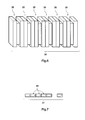
- the fiber negative electrode and the fiber positive electrode are stacked alternately in such a manner that horizontal end positions of the fiber negative electrode and horizontal end positions of the fiber positive electrode are displaced from each other, and the fiber negative electrode and the fiber positive electrode are press-formed vertically.
- a separator coating is formed on a surface of the fiber negative electrode or on a surface of the fiber positive electrode.
- a negative electrode terminal and a positive electrode terminal are disposed at end portions of the press-formed fiber negative and positive electrodes.
- the fiber negative electrode and the fiber positive electrode are fixed by means of an adhesive.
- a battery stack (high-capacity battery) may be formed by combining a plurality of the secondary batteries, an insulating framework member, and an electrically conductive framing member.
- a battery module may be formed by stacking a plurality of the secondary batteries.
- a battery module may be formed by stacking a plurality of the battery stacks (high-capacity batteries).
- the present invention also relates to a negative electrode for use in a secondary battery using protons as an intercalating species.
- the negative electrode includes a carbon fiber.
- the carbon fiber has a surface on which a negative electrode active material coating is formed.
- the negative electrode active material coating is represented by a chemical formula 1 which is A a M b X c Z d .
- A represents at least one kind of metal element selected from the group consisting of Li, Na, K, Rb, Cs, Be, Mg, Ca, Sr, and Ba
- M represents at least one kind of transition metal element selected from the group consisting of Ti, V, Cr, Mn, Fe, Co, Ni, Cu, Nb, Mo, Ru, Pd, Ag, Ta, W, Pr, Sm, Eu, and Pb
- X represents at least one kind of typical element selected from the group consisting of B, Al, Si, P, S, Ga, and Ge
- Z represents at least one kind of typical element selected from the group consisting of O, S, N, F, Cl, Br, and I; and 0 ⁇ a ⁇ 6, 1 ⁇ b ⁇ 5, 0 ⁇ c ⁇ 4, 0 ⁇ d ⁇ 12, and 0 ⁇ a/b ⁇ 4.
- the secondary battery according to the present invention an influence of electrode oxidation due to overcharging is very small, and charging and discharging are performed by using protons as an intercalating species. This makes it possible to attain high power capability.
- the secondary battery according to the present invention has high capacity, and is capable of achieving a cycle life of 50 cycles or more.
- a secondary battery according to the present invention includes: a fiber negative electrode including a carbon fiber, the carbon fiber having a surface on which a negative electrode active material coating is formed, the negative electrode active material coating containing a compound represented by a chemical formula 1 which is A a M b X c Z d ; a fiber positive electrode including a carbon fiber, the carbon fiber having a surface on which a positive electrode active material coating is formed, the positive electrode active material coating containing nickel hydroxide; an aqueous electrolyte solution; and a separator.
- the negative electrode active material coating has a surface uncoated with an electrically conductive material.
- A represents at least one kind of metal element selected from the group consisting of Li, Na, K, Rb, Cs, Be, Mg, Ca, Sr, and Ba
- M represents at least one kind of transition metal element selected from the group consisting of Ti, V, Cr, Mn, Fe, Co, Ni, Cu, Nb, Mo, Ru, Pd, Ag, Ta, W, Pr, Sm, Eu, and Pb
- X represents at least one kind of typical element selected from the group consisting of B, Al, Si, P, S, Ga, and Ge
- Z represents at least one kind of typical element selected from the group consisting of O, S, N, F, Cl, Br, and I; and 0 ⁇ a ⁇ 6, 1 ⁇ b ⁇ 5, 0 ⁇ c ⁇ 4, 0 ⁇ d ⁇ 12, and 0 ⁇ a/b ⁇ 4.
- Examples of the compound represented by the chemical formula 1 include vanadium trioxide, vanadium pentoxide, lithium vanadate, lithium chromate, lithium manganese oxide, lithium cobalt oxide, lithium ferrite, sodium ferrite, lithium nickel oxide, lithium titanate, iron phosphate, lithium iron phosphate, lithium iron silicate, and cobalt phosphate.
- the compound represented by the chemical formula 1 may contain different typical elements, alkali metal elements, or alkaline-earth metal elements.
- a first feature of the secondary battery according to the present invention is to use, as a negative electrode active material, a compound containing an element capable of redox reactions.
- the compound represented by the chemical formula 1 is different from a hydrogen storage alloy which serves as a negative electrode material of a nickel-metal hydride battery, and is also different from a carbon material, or a silicon material, which serves as a negative electrode material of a conventional lithium ion battery.
- a second feature of the secondary battery according to the present invention is to use protons as an intercalating species.
- Protons have higher mobility in an electrolyte solution than lithium ions, and allow the secondary battery to exert its high-power charge/discharge capability.
- the use of protons also allows the secondary battery to be used in an atmosphere under a severe temperature.
- protons as an intercalating species smaller than lithium ions.
- fuel cells and nickel-metal hydride batteries use protons as an intercalating species.
- hydrogen molecules i.e., hydrogen gas
- protons receive electrons at the surface of a hydrogen storage alloy during charging to become hydrogen atoms, and the hydrogen atoms are absorbed into the metal.
- a third feature of the secondary battery according to the present invention is that both of the negative electrode and the positive electrode are fiber electrodes.
- the electrodes By forming the electrodes not as plate electrodes but as fiber electrodes, the surface area of the electrodes is significantly increased. Accordingly, it is expected that chemical reactivity of the electrodes is greatly increased. It is considered more effective to form a stacked body of fiber positive electrodes and/or fiber negative electrodes on which a thin separator coating is formed, thereby increasing a separator surface area in addition to the electrode surface area and reducing an inter-electrode distance to reduce a moving distance of protons.
- a negative electrode active material coating containing the compound represented by the chemical formula 1 can be formed on a carbon fiber (or on Ni plating if the carbon fiber is plated with Ni) by performing the steps of: (1-1) forming a tubular coating of a transition metal oxide or a transition metal hydroxide on the surface of the carbon fiber; and (1-2) hydrothermally treating the coating obtained in the step (1-1) at 100 to 250 °C in a Li ion-containing aqueous solution in the presence of an oxidant, thereby forming a Li-doped or Na-doped transition metal oxide coating as a negative electrode active material coating.
- the diameter of the carbon fiber, which serves as a negative electrode current collector is not particularly limited but may be determined with reference to the thickness of a conventional nickel positive electrode current collector. Specifically, a positive electrode using a sintered nickel substrate or a positive electrode using a foamed nickel substrate has a thickness of 300 ⁇ m or greater. Therefore, it is preferred that the diameter of an electrically conductive fiber used as a negative electrode current collector as well as a positive electrode current collector in the present invention is much less than 300 ⁇ m. Accordingly, the diameter of each single fiber forming the electrically conductive fiber is preferably 0.1 to 100 ⁇ m, and more preferably, 2 to 50 ⁇ m.
- the length and aspect ratio of the carbon fiber are not particularly limited, it is preferred that the length is approximately 10 to 1000 mm, and the aspect ratio is approximately 2000 to 200000.
- 100 to 20000 single carbon fibers, which serve as negative electrode current collectors are bundled together into one carbon fiber tow. More preferably, 1000 to 5000 single carbon fibers are bundled together into one carbon fiber tow.
- a single electrode (negative electrode) may be formed by fixing one end of the fiber tow by means of a solderless terminal. Alternatively, a carbon fiber that is formed by twisting 2 to 10 single fibers together may be used.
- a fiber negative electrode may be formed by bundling together 50 to 1000 such twisted threads of carbon fibers.
- the number of fibers forming one fiber tow is less than 100, their function as a negative electrode or positive electrode active material retainer, that is, the fibers' function of preventing dropping of the active material by being pressure-bonded to each other, may decrease. On the other hand, if the number of fibers forming one fiber tow is more than 2000, it becomes difficult to uniformly form a tubular active material coating on each fiber.
- carbon fibers are electrically conductive fibers, they can be directly used as fibrous current collectors.
- the electrical conductivity of the surface of the carbon fibers can be further improved by plating the carbon fibers with Ni.
- it is very effective to form a Ni plating coating on the carbon fibers which serve as current collectors.
- Applicable methods of plating carbon fibers with Ni include: a physical thin film formation method; a method of depositing Ni through thermal decomposition of nickel carbonyl; an electroless plating method; and an electrolytic plating method.
- a method most suitable for uniformly forming a Ni plating coating on each of 1000 or more single fibers forming a carbon fiber tow is as follows: forming a thin Ni coating by electroless Ni plating; and then performing electrolytic Ni plating thereon.
- Electroless Ni plating is a method in which Ni metal deposition is performed through chemical reduction action. This method does not require application of an electric current. Therefore, with this method, a Ni coating having a uniform thickness can be formed on a carbon fiber tow even if the carbon fiber tow has insufficient electrical conductivity and has a complex and intricate shape. Accordingly, if a thin Ni coating (Ni plating coating) is formed on a carbon fiber tow by electroless Ni plating prior to performing electrolytic Ni plating, then the thin Ni coating can be used as an undercoating for forming a Ni plating coating with improved thickness uniformity. Furthermore, since the electrical conductivity of the carbon fiber surface is improved with this method, plating efficiency at the time of performing electrolytic Ni plating is improved. This makes it possible to realize efficient mass manufacturing.
- Applicable methods of electroless Ni plating on carbon fibers include: a well-known nickel-phosphorus alloy plating (phosphorus content: 5 to 12 %) deposition method in which a hypophosphite is used as a reductant; and a nickel-boron alloy plating (boron content: 0.2 to 3%) deposition method in which a reduction action of dimethylamine borane is utilized.
- a thickness of 0.1 to 0.5 ⁇ m of the Ni plating coating formed by such an electroless Ni plating method is satisfactory.
- electrolytic Ni plating on the carbon fibers, on which the electroless Ni plating has previously been performed may be performed in a well-known Watts bath.
- the thickness of a Ni plating coating formed by an electrolytic plating method is preferably 0.5 to 15 ⁇ m, and more preferably, 1 to 8 ⁇ m If the thickness of the Ni plating coating is less than 0.5 ⁇ m, there is a possibility that sufficient electrical conductivity cannot be obtained. If the Ni plating coating has a thickness of 0.5 to 15 ⁇ m, sufficient electrical conductivity is obtained, and in addition, fine irregularity of the carbon fiber surface can be reflected in the Ni plating.
- Any transition metal oxide compound or transition metal hydroxide compound may be used without specific restriction so long as a coating of the compound can be formed on the carbon fiber surface.
- the compound include TiO, Ti 2 O 3 , TiO 2 , V 2 O 3 , V 2 O 5 , CrO, Cr 2 O 3 , CrO 2 , MnO, Mn 3 O 4 , Mn 2 O 3 , MnO 2 , MnO 3 , FeO, Fe 3 O 4 , Fe 2 O 3 , CoO, Co 2 O 3 , Co 3 O 4 , CoO 2 , NiO, Ni 3 O 4 , Ni 2 O 3 , NiO 2 , Cu 2 O, CuO, and ZnO.
- the method of forming a tubular coating of either a transition metal oxide or a transition metal hydroxide on the carbon fiber (or on a Ni plating if the carbon fiber is plated with Ni) may be, but not limited to, a slurry method, a physical thin film formation method, an aerosol deposition method, an electroplating method, or an electrodeposition method.
- a slurry method a physical thin film formation method
- an aerosol deposition method an electroplating method
- an electrodeposition method an electrodeposition method.
- slurry that is obtained by dispersing transition metal oxide particles or transition metal hydroxide particles together with organic matter in a solvent is applied onto a current collector. Then, the solvent is vaporized and thereby an electrode is formed. After an active material is applied onto the current collector, the current collector may be passed through a slit or a die, and thereby the thickness of the slurry can be thinly and uniformly adjusted.
- Examples of the physical thin film formation method include a vapor deposition method and a sputtering method. With these methods, a highly dense coating of a transition metal oxide or a transition metal hydroxide can be formed on the carbon fiber surface without using an additive such as a thickener or a binder. It should be noted that a treatment time for forming the transition metal oxide coating or the transition metal hydroxide coating becomes long if the coating is formed to have a large thickness.
- the aerosol deposition method is a method of applying, at once, a jet of transition metal oxide powder or transition metal hydroxide powder existing in a positive pressure atmosphere to a current collector existing in a negative pressure atmosphere, thereby forming a coating of the transition metal oxide or the transition metal hydroxide on the current collector. It should be noted that if the transition metal oxide powder or the transition metal hydroxide powder has low ductility, a uniform coating of the transition metal oxide or the transition metal hydroxide is not easily formed.
- the electroplating method is a method of electrochemically forming a metal coating on the carbon fiber surface.
- a transition metal oxide layer or a transition metal hydroxide layer cannot be directly formed on the carbon fiber surface. Therefore, it is necessary that the carbon fiber surface is first plated with a transition metal, and then the transition metal is oxidized through high-temperature oxidation treatment.
- the high-temperature oxidation treatment may be, for example, to increase the temperature to 500 to 1000 °C under an oxidizing atmosphere.
- Conditions for performing the electroplating method are not particularly limited but depend on a metal to be plated on the carbon fiber surface.
- concentration of a transition metal salt used for the plating may be adjusted to fall within the range of 0.01 to 1 mol/L, and the electroplating may be performed with a current density of 1 mA/cm 2 to 0.1 A/cm 2 . In this manner, the carbon fiber may be plated with the transition metal.
- a base material on which a coating is to be formed i.e., the carbon fiber serving as a current collector
- an electrode to serve as a counter electrode are immersed in a solution that contains the compositions of the coating to be formed, and then a current is applied.
- the coating is formed on the base material.
- a current is applied while the base material is used as a cathode. In this manner, a transition metal oxide coating or a transition metal hydroxide coating can be formed on the surface of the base material.
- a current may be applied while using the base material as an anode to perform anodic oxidation and also to cause the base material to capture the composition ions present in a bath.
- a coating can be formed on the surface of the base material.
- a metal oxide coating can be obtained by drying the metal hydroxide coating in an air atmosphere at a temperature of 100°C or higher.
- a transition metal oxide coating or a transition metal hydroxide coating can be directly formed on the carbon fiber.
- conditions for performing the electrodeposition method are not particularly limited, it is preferred that the concentration of a metal salt to be deposited is adjusted to fall within the range of 0.01 to 1 mol/L, and the electrodeposition is performed with a current density of 1 mA/cm 2 to 0.1 A/cm 2 .
- the electroplating method or the electrodeposition method to form a transition metal oxide coating or a transition metal hydroxide coating.
- a transition metal oxide coating or a transition metal hydroxide coating can be formed on the surface of the carbon fiber, so long as the carbon fiber is in contact with an electroplating bath or an electrodeposition bath.
- these methods realize high degree of adhesion of the coating and high degree of smoothness of the coating surface, and allow a uniform coating of a transition metal oxide or a transition metal hydroxide to be readily formed at low cost.
- the electrodeposition method is the most preferable method since it allows a coating of a transition metal oxide or a transition metal hydroxide to be directly formed on the carbon fiber which serves as a current collector.
- a conductive agent may be dispersed in a treatment bath (an electroplating bath or an electrodeposition bath) when performing the electroplating or electrodeposition, such that the conductive agent is co-deposited with a transition metal oxide or a transition metal hydroxide.
- a treatment bath an electroplating bath or an electrodeposition bath
- the co-deposition method is performed in combination with the electroplating method, there is a risk that the conductive agent is oxidized in the oxidation treatment performed at a latter stage.
- the conductive agent to be added into the electroplating bath or the electrodeposition bath may be any material, so long as it has electrical conductivity and stably exists within a charge/discharge voltage range.
- preferred examples of the conductive agent include a carbon material or a nickel fine powder. It is preferred to add approximately 1 to 20 wt % of the conductive agent to the electrodeposition bath. It is preferred to further add approximately 1 wt % of a surfactant to the electrodeposition bath since the addition of the surfactant facilitates the dispersion of the conductive agent in the electrodeposition bath.
- the metal alkoxide herein refers to a compound, in which the hydrogen of the hydroxyl group of an alcohol molecule is replaced by a metal atom and which is represented by the following general formula: M(OR) n (M: metal, R: alkyl group, n: the oxidation number of a metal element).
- M metal, R: alkyl group, n: the oxidation number of a metal element.
- Alkali metals, alkaline-earth metals, transition metals, rare earth elements, and various elements in groups 13 to 16 of the periodic table may form metal alkoxides.
- a transition metal oxide layer or a transition metal hydroxide layer can be formed on the carbon fiber surface. This method is applicable if it is difficult to form a metal oxide coating or a metal hydroxide coating through the electrodeposition method.
- the amount of coating of a transition metal oxide or a transition metal hydroxide layered on the carbon fiber surface is 1 to 30 mg/cm 2 . If the amount of coating to be layered on the carbon fiber surface is set to fall within this range, a necessary capacity for the battery can be obtained, and also, delamination between the negative electrode active material coating and the current collector becomes less likely to occur.
- the thickness of the negative electrode active material coating is not particularly limited, it is preferred that the thickness is set to 0.5 ⁇ m to 30 ⁇ m, and more preferably, 1 ⁇ m to 10 ⁇ m.
- the carbon fiber obtained in the step (1-1), on which the transition metal oxide coating or the transition metal hydroxide coating is formed is hydrothermally treated at 100 to 250 °C in a Li ion-containing or Na ion-containing aqueous solution in the presence of an oxidant.
- the transition metal oxide coating or the transition metal hydroxide coating becomes a coating of a Li-doped or Na-doped transition metal oxide which serves as a negative electrode active material.
- a transition metal oxide coating is formed on the carbon fiber surface, which transition metal oxide coating is represented by the following formula (1): M g O h (wherein: M is at least one kind of transition metal selected from the group consisting of Ti, V, Cr, Mn, Fe, Co, and Ni; 1 ⁇ g ⁇ 3; and 1 ⁇ h ⁇ 5). Then, the coating is heat treated in a Li ion-containing solution in the presence of an oxidant.
- Li i M j O k Li-doped transition metal oxide represented by the following formula (2): Li i M j O k (wherein: 0 ⁇ i ⁇ 2; 1 ⁇ j ⁇ 5; 2 ⁇ k ⁇ 5; and M is the same as in the formula (1)).
- the resultant Li-doped transition metal oxide is a compound represented by the following formula (2-1): Li i1 Mn j1 O k1 (wherein: the valence of Mn is in the range of 3 to 4; 0 ⁇ i1 ⁇ 2; 1 ⁇ j1 ⁇ 2; and 2 ⁇ k1 ⁇ 4).
- the number of atoms of each element is suitably specified in accordance with its valence.
- the negative electrode active material of which is an oxide containing lithium and manganese such as Li 1+x Mn 2 O 4 or Li x Mn 2 O 4 , Mn dissolution occurs at high temperatures, which may result in significant capacity deterioration.
- a negative electrode active material in which a part of Mn is replaced by, for example, Al, P, Ti, Cr, Fe, Co, Ni, Cu, Sr, Y, Zr, In, Sn, Bi, or a rare earth element.
- the element that replaces a part of Mn is Al, Bi, Ni, or a rare earth element.
- the element that replaces a part of Mn is Al or Ni.
- a transition metal oxide coating is formed, which is represented by the following formula (1-2): (Mn 1-x A x ) 3 O 4 (wherein: A is at least one kind of element selected from the group consisting of Al, Ti, Cr, Fe, Co, Ni, Cu, Sr, Y, Zr, Bi, and a rare earth element; and 0.05 ⁇ x ⁇ 0.25). Thereafter, the transition metal oxide coating is doped with Li.
- Li-doped transition metal oxide coating is formed, which is represented by the following formula (2-2): Li i2 (Mn 1-y A y ) j2 O k2 (wherein: the valence of Mn is in the range of 3 to 4; 0 ⁇ i2 ⁇ 2;1 ⁇ j2 ⁇ 2; 2 ⁇ k2 ⁇ 4; 0.05 ⁇ y ⁇ 0.25; and A is the same as in the formula (1-2)).
- a coating containing two or more kinds of metal oxides for example, a Ni oxide and a Mn oxide, may be formed, and then hydrothermal treatment may be performed in a Li ion-containing solution in the presence of an oxidant.
- a fiber negative electrode of which an active material is a lithium nickel manganese oxide coating can be obtained.
- a transition metal oxide coating containing two or more kinds of metal oxides may be formed by dispersing fine particles of transition metal oxides in an electrodeposition bath and co-depositing them, and then hydrothermal treatment may be performed in the same manner as above.
- the bismuth salt tends to sediment.
- Such sedimentation of the bismuth salt can be suppressed to some extent by adding ammonia or a polysaccharide (e.g., mannitol) to the electrodeposition bath.
- the following method may be used: dispersing a fine powder of bismuth oxide into a nickel nitrate aqueous solution and co-depositing the bismuth oxide with nickel hydroxide.
- Non-limiting examples of the oxidant include air, oxygen, ozone, chlorine, bromine, a chlorate, peroxodisulfuric acid, a hypochlorite, and a hydrogen peroxide solution.
- a hypochlorite is particularly preferred as the oxidant.
- hypochlorites sodium hypochlorite is preferred.
- a Li ion (or Na ion) amount and an oxidant amount vary depending on the form of oxidation, or the amount, of the transition metal oxide. That is, a Li ion (or Na ion) amount and an oxidation equivalent or a reducing equivalent necessary for a starting material to be a target product may be estimated.
- LiMnO 2 the valence of Mn is 3+
- LiMn 2 O 4 the valence of Mn is 3.5+
- LiMn 2 O 4 the valence of Mn is 3.5+
- LiMnO 2 the valence of Mn is 3+
- the oxidant or the reductant in reality, however, it is difficult to cause an ideal reaction. Therefore, it is preferred to add the oxidant or the reductant by an amount that is 1 to 8 times as much as a theoretical equivalent. It is more preferred to add the oxidant or the reductant by an amount that is 1.5 to 4 times as much as the theoretical equivalent.
- the solution may be heated as it is.
- the solution is under acidic conditions, in particular, if the pH value (hydrogen ion concentration index) is small, then it is preferred that the solution is heated with a substance for increasing the pH value added thereto.
- the substance to be added include: an alkali hydroxide such as sodium hydroxide, potassium hydroxide, or lithium hydroxide; an ammonia compound such as ammonia gas or ammonia water; and an alkaline carbonate compound such as sodium carbonate, potassium carbonate, lithium carbonate, or ammonium carbonate.
- any solution in which Li ions are dissolved may be used as the Li ion-containing solution in the hydrothermal treatment.
- an aqueous solution of a water-soluble lithium compound may be used.
- a lithium chloride aqueous solution, a lithium nitrate aqueous solution, or a lithium hydroxide aqueous solution may be suitably used as the Li ion-containing solution.
- a single kind or a mixture of two or more kinds of these water-soluble lithium compounds may be used to prepare the Li ion-containing solution.
- the water-soluble lithium compounds used here may be either anhydrous compounds or hydrated compounds.
- any solution in which Na ions are dissolved may be used as the Na ion-containing solution in the hydrothermal treatment.
- an aqueous solution of a water-soluble sodium compound may be used.
- a sodium chloride aqueous solution, a sodium nitrate aqueous solution, or a sodium hydroxide aqueous solution may be suitably used as the Na ion-containing solution.
- a single kind or a mixture of two or more kinds of these water-soluble sodium compounds may be used to prepare the Na ion-containing solution.
- the water-soluble sodium compounds used here may be either anhydrous compounds or hydrated compounds.
- the usage amount of the water-soluble lithium compound may be determined such that Li is added to the solution by a necessary amount or more for obtaining a target product, in terms of the elemental molar ratio of Li to the number of moles of the transition metal in the transition metal oxide or transition metal hydroxide subjected to the hydrothermal treatment. It is preferred to add Li by an amount that is one to five times as much as a theoretical amount. It is more preferred to add Li by an amount that is one to three timesas much as the theoretical amount.
- the concentration of the water-soluble lithium compound is preferably in the range of 0.05 to 10 mol/L, and more preferably, in the range of 1 to 6 mol/L. The same is true of the water-soluble sodium compound.
- the temperature at which to perform the hydrothermal treatment is 100 to 250 °C.
- the temperature at which to perform the hydrothermal treatment is 100 to 200 °C. Even if the temperature of the hydrothermal treatment is lower than 100 °C, the reaction still progresses. In this case, however, the reaction rate is slow. Therefore, it is preferred that the temperature of the hydrothermal treatment is 100 °C or higher. If the hydrothermal treatment is to be performed at a temperature higher than 250 °C, then a large-scale device is necessary for the hydrothermal treatment, resulting in a high cost.
- the hydrothermal treatment is performed in the presence of an oxidant in the following manner: the carbon fiber on which a transition metal oxide coating or a transition metal hydroxide coating is formed is immersed in the Li ion-containing or Na ion-containing solution; the solution in which the carbon fiber is immersed is contained in a corrosion-resistant and pressure-resistant container and the container is sealed; and the hydrothermal treatment is performed under pressure or under saturated vapor pressure.
- the hydrothermal treatment may be performed under a pressure of 0.05 to 40 MPa. Setting the pressure within this range allows the transition metal oxide to be sufficiently Li-doped or Na-doped, and eliminates the necessity of using a large-scale corrosion-resistant and pressure-resistant container. Accordingly, setting the pressure within this range is also preferable from an economic point of view. In view of the above, it is particularly preferred that the hydrothermal treatment is performed under a pressure of 0.1 to 10 MPa.
- the hydrothermal treatment time depends on the temperature at which to perform the hydrothermal treatment.
- the hydrothermal treatment time may be five hours or longer if the temperature is in the range of 100 to 200 °C, or may be three hours or longer if the temperature is in the range of 200 to 400 °C.
- the hydrothermal treatment time is suitably set so as not to cause dropping of the negative electrode active material coating formed on the carbon fiber surface.
- it is preferred that the hydrothermal treatment time is within the range of 5 to 50 hours. More preferably, the hydrothermal treatment time is within the range of 10 to 30 hours.
- a fiber negative electrode of which the carbon fiber surface is coated with the Li-doped or Na-doped transition metal oxide i.e., coated with a negative electrode active material
- the fiber negative electrode can be used as a more favorable electrode.
- a negative electrode active material coating i.e., a negative electrode active material layer
- a negative electrode active material layer having a tubular shape
- a step where a negative electrode active material is made into an electrode, which is necessary in the conventional art, is no longer necessary. That is, the production of the negative electrode active material and the fabrication of the fiber negative electrode can be performed at the same time.
- the fiber negative electrode according to the present invention is formed such that a flaky negative electrode active material agglomerates into a mass; the mass is perpendicularly adhered to a current collector; and a porous negative electrode active material coating is formed on the fiber negative electrode. Accordingly, the electrode has a significantly large surface area and a structure that allows an electrolyte solution to easily permeate, and is capable of mitigating a stress that occurs due to expansion and contraction of the negative electrode active material.
- the current collector is a thin columnar carbon fiber, a tubular negative electrode active material coating is formed on the carbon fiber surface. As a result, a significantly large electrode surface area is obtained.
- the negative electrode active material coating forms a fully tubular shape, its volume change due to charging and discharging is suppressed. Accordingly, even in a case where expansion and contraction repeatedly occur, detachment or dropping of the negative electrode active material coating is less likely to occur as compared to a plate electrode. If fiber negative electrodes of this type are bundled together, the fibers of the electrodes are pressure-bonded to each other and thus effectively prevent the dropping of the negative electrode active material coating. Consequently, the fiber negative electrode according to the present invention is long-lived and has excellent electrode characteristics.
- a positive electrode active material coating that contains nickel hydroxide can be formed on the surface of a carbon fiber by performing the following steps of: (2-1) plating the carbon fiber with Ni; (2-2) performing electrolysis in a nickel nitrate bath where the Ni-plated carbon fiber is used as a cathode and a nickel plate is used as an anode, thereby electrodepositing a positive electrode active material containing nickel hydroxide on the surface of the carbon fiber; and (2-3) immersing the carbon fiber, which is coated with nickel hydroxide, in a caustic alkali aqueous solution.
- the diameter of a single carbon fiber serving as a positive electrode current collector is preferably 0.1 to 100 ⁇ m, and more preferably, 2 to 50 ⁇ m.
- nickel hydroxide has such a characteristic that spherical crystal growth tends to occur, if the diameter of the single fiber is 0.1 to 100 ⁇ m, and more particularly, 2 to 50 ⁇ m, then a tubular coating of nickel hydroxide can be formed on the carbon fiber surface while maintaining the fiber's mechanical strength.
- the nickel hydroxide coating thus formed does not easily detach from the carbon fiber even if expansion and contraction occur due to charging and discharging, that is, the nickel hydroxide coating exhibits excellent adhesion.
- 100 to 20000 single carbon fibers, which serve as positive electrode current collectors, are bundled together into one carbon fiber tow. More preferably, 1000 to 5000 single carbon fibers are bundled together into one carbon fiber tow.
- a single electrode (positive electrode) may be formed by fixing one end of the fiber tow by means of a solderless terminal. Alternatively, a carbon fiber that is formed by twisting 2 to 10 single fibers together may be used.
- a fiber positive electrode may be formed by bundling together 50 to 2000 such twisted threads of carbon fibers.
- the theoretical capacity of nickel hydroxide (positive electrode) and the theoretical capacity of the fiber negative electrode according to the present invention are 289 mAh/g and 250 mAh/g, respectively, which are close values.
- the negative electrode capacity is set to be higher than the positive electrode capacity (i.e., the battery capacity is limited by the positive electrode).
- the number of negative electrode fibers may be set to be more than the number of negative electrode fibers.
- carbon fibers are originally hydrophobic, carbon fibers may be hydrophilized by using a surfactant. Such hydrophilized carbon fibers allow nickel hydroxide to be electrodeposited on their surface. However, since such hydrophilization treatment alone is not enough for the carbon fibers to obtain sufficient electrical conductivity, nickel hydroxide which is an electrodeposit is deposited non-uniformly among the carbon fibers. In view of this, prior to the electrodeposition of nickel hydroxide, each carbon fiber was uniformly coated with Ni. This made it possible to form, on the surface of each carbon fiber, a nickel hydroxide coating that has a concentrically uniform thickness. The reason for this relates to the electrical conductivity of the carbon fiber surface.
- the electrical resistivity of a carbon fiber is approximately 4 ⁇ 10 -7 ⁇ m
- the electrical resistivity is decreased to approximately 6 ⁇ 10 -8 ⁇ m when the carbon fiber is coated with Ni.
- the electrical conductivity of the carbon fiber surface is increased by approximately ten times.
- the Ni coating brings improvements in the electrical conductivity and hydrophilicity of the carbon fiber surface, and makes it possible to form a uniform nickel hydroxide coating through electrodeposition.
- the most suitable method for forming a Ni coating on a carbon fiber is as follows: forming a thin Ni coating by electroless Ni plating; and then performing electrolytic Ni plating thereon.
- the method in which the electroless Ni plating and the electrolytic Ni plating are performed on the carbon fiber is the same as in the fiber negative electrode fabrication method.
- Ni plating that reflects fine irregularity of the carbon fiber surface has been performed, if an electrodeposit is deposited onto the irregular portions on the carbon fiber surface in the following electrodeposition process, then an anchor effect is exerted, which brings an advantage that the adhesion of nickel hydroxide, which is a positive electrode active material, is increased.
- a preferable fiber current collector is one having a porous surface, exerting an anchor effect, and capable of maintaining electrical conductivity.
- Such a fiber current collector can be obtained by forming a Ni plating coating having a preferable thickness of 0.5 to 15 ⁇ m or a more preferable thickness of 1 to 8 ⁇ m on the surface of a carbon fiber through an electroless plating method followed by an electrolytic plating method.
- electrolysis is performed in a nickel nitrate bath, in which the carbon fiber that has gone through the step (2-1) is used as a cathode and a nickel plate is used as an anode.
- a positive electrode active material coating containing nickel hydroxide is electrodeposited on the surface of the Ni plating coating of the carbon fiber.
- the concentration of a nickel nitrate aqueous solution used in the electrodeposition is preferably 0.05 to 1.5 mol/L, and more preferably, 0.3 to 1 mol/L.
- a current density at the time of performing the electrodeposition is preferably 0.1 to 30 mA/cm 2 , and more preferably, 1 to 20 mA/cm 2 .
- the thickness of the positive electrode active material coating containing nickel hydroxide is preferably 0.5 to 30 ⁇ m, and more preferably, 5 to 15 ⁇ m. If the thickness is less than 0.5 ⁇ m, there is a risk that sufficient battery capacity cannot be obtained.
- the thickness of the positive electrode active material coating containing nickel hydroxide is greater than 30 ⁇ m, the thickness is formed unevenly, which may result in an increased likelihood of dropping of the positive electrode active material coating from the carbon fiber surface when the positive electrode active material coating expands due to charging and discharging.
- the inventors of the present invention have confirmed that the positive electrode active material coating containing nickel hydroxide, which is formed by the electrodeposition method, is in an amorphous state since nickel nitrate or an ammine complex partially remains in the active material coating. Therefore, if charging and discharging are performed when the active material coating is in such a state, the active material utilization is limited to approximately 30 % (in a case where the theoretical capacity is 289 mAh/g).
- the inventors took into consideration various treatment methods such as heating an electrodeposition bath or adjusting pH of the bath, and found that hydrothermal treatment using a high-temperature caustic alkali aqueous solution was most effective. Hydrothermally treated nickel hydroxide was observed with an electron microscope, and it was confirmed that amorphous nickel hydroxide had transformed into crystalline nickel hydroxide. A fiber positive electrode containing such nickel hydroxide was used in charging and discharging, and it was confirmed that the active material utilization was 100 % (in a case where the theoretical capacity was 289 mAh/g).
- Preferable crystallinity of nickel hydroxide is such that the half-value width of an X-ray diffraction peak is 5° or less in terms of the angle of diffraction. If the half-value width is greater than 5°, it means that impurities such as nitric radicals, which disturb the atomic arrangement of crystals, are contained in a large amount. In such a state, a function of nickel hydroxide as a positive electrode active material is hindered, and the active material utilization is reduced significantly.
- the half-value width is less than 5° in terms of the angle of diffraction, it is considered that impurities that disturb the atomic arrangement of crystals and hinder the function of nickel hydroxide as an active material are substantially removed, and an active material utilization that corresponds to almost 100 % of the positive electrode's guaranteed charge capacity can be obtained.
- Sodium hydroxide, potassium hydroxide, or lithium hydroxide can be used herein as a caustic alkali.
- an aqueous solution in which these caustic alkalis are mixed can be used herein as a caustic alkali aqueous solution.
- the caustic alkali aqueous solution is preferably a sodium hydroxide aqueous solution since it allows a crystalline nickel hydroxide to be obtained within a short period of time.
- the concentration of the caustic alkali in the aqueous solution is preferably, but not limited to, 10 to 30 wt %.
- a temperature and a time for immersion in the aqueous solution are preferably, but not limited to, 10 minutes to 24 hours at 40 to 110 °C, and more preferably, 1 to 5 hours at 60 to 80 °C.
- Nitric radicals which are known as a cause of self-discharge, are removed through immersion treatment in the caustic alkali aqueous solution, and thus, such immersion treatment in the caustic alkali aqueous solution is very effective to suppress the self-discharge of the fiber positive electrode.
- the immersion treatment is particularly important in applications where self-discharge such as intermittent discharge becomes an issue.
- a fiber electrode assembly can be formed by alternately stacking a fiber negative electrode, a separator, and a fiber positive electrode in such a manner that their horizontal end positions are displaced from each other.
- fiber negative electrodes and fiber positive electrodes are formed such that a separator coating is formed on each fiber negative electrode and/or each fiber positive electrode, one fiber electrode and another fiber electrode serving as a counter electrode of the one fiber electrode are stacked alternately and then pressed together. In this manner, an electrode assembly formed of fiber negative electrodes, separators, and fiber positive electrodes is obtained.
- end positions of the respective fiber negative electrodes are displaced, by approximately 1 to 5 mm, from end positions of the respective fiber positive electrodes. This makes it easy to form terminals.
- a block-shaped fiber electrode assembly can be obtained by performing press forming on a stack of a sheet-like fiber negative electrode and a sheet-like fiber positive electrode, each of which is obtained by spreading a fiber tow.
- an adhesive is thinly applied to the fiber negative electrode and/or the fiber positive electrode prior to stacking them if it is desired to increase the adhesion between the fiber negative electrode and the fiber positive electrode.
- any adhesive can be used without specific restriction, so long as the adhesive does not reduce the fiber electrode performance, separator performance, or aqueous electrolyte solution performance. Even if the adhesive is dissolved into the electrolyte solution, it does not cause a problem so long as the dissolution into the electrolyte solution occurs after the fiber electrode assembly has been fixed in a battery casing.
- terminals When forming terminals of the press-formed fiber electrode assembly, terminals can be formed by welding metal plates to negative and positive electrode sides, respectively, of the electrode assembly or by bringing metal plates into contact with, and then pressing the metal plates against, the fiber electrodes from both the sides.
- the sheet-like fiber negative electrodes and the sheet-like fiber positive electrodes are in a simply stacked state, then there is a possibility that when a metal plate to serve as a terminal comes into contact with an electrode, the metal plate also comes into contact with a counter electrode, causing short-circuiting.
- a negative electrode terminal portion and a positive electrode terminal portion of the electrode assembly are sealed with resin; thereafter, the resin is ground by a cutter or a grinder until the negative electrode terminal portion and the positive electrode terminal portion are exposed; and metal plates are held to the exposed negative electrode and positive electrode terminal portions, respectively, to perform pressing from both sides.
- any resin can be used without specific restriction, so long as the resin has excellent resistance to an electrolyte solution and an excellent insulating property.
- a polymer material having an excellent insulating property, or a commercially available synthetic adhesive having excellent resistance to an electrolyte solution and an excellent insulating property, may be used as the resin.
- the press-formed fiber electrode assembly is inserted in a battery casing, and an aqueous electrolyte solution is injected thereinto.
- a fiber battery secondary battery
- each fiber negative electrode is squeezed in between fiber positive electrodes while electrical insulation between the positive and negative fiber electrodes is maintained by the separator, and therefore, a distance to a counter electrode becomes very short. This makes it possible to significantly reduce internal resistance at the time of charging and discharging. Since a separator coating is formed on each single fiber, a significantly large separator surface area is obtained. As a result, the charging speed and discharging speed of the battery are greatly improved as compared to conventional secondary batteries, and also, ultrafast charging and large current discharging are realized.
- any aqueous solution having proton conductivity or hydroxide ion conductivity may be used as the aqueous electrolyte solution of the secondary battery according to the present invention.
- the aqueous electrolyte solution include: (1) an aqueous solution of an inorganic acid such as hydrochloric acid, sulfuric acid, nitric acid, or phosphoric acid; (2) an aqueous solution of an organic acid such as formic acid, acetic acid, oxalic acid, or citric acid; and (3) an aqueous alkali solution such as an alkali metal hydroxide aqueous solution.
- a caustic alkali aqueous solution is preferred from the standpoint of allowing nickel hydroxide, which serves as a positive electrode active material, to stably exist.
- a potassium hydroxide aqueous solution or a sodium hydroxide aqueous solution may be used as the caustic alkali aqueous solution.
- the electrolyte solution is preferably a caustic alkali aqueous solution.
- the aqueous electrolyte solution is impregnated into or retained by a polymer or a ceramic in order to electrically insulate fiber negative electrodes from fiber positive electrodes within a battery cell.
- the polymer include: a polymer such as a polyamide, polyethylene, polypropylene, polyvinyl alcohol, cellophane, or sodium polyacrylate; a complex polymer formed of these polymers; and a weakly acidic cation-exchange resin.
- a material obtained from hydrolyzing any of these polymers may be used.
- any polymer material may be used as a separator material without specific restriction, so long as the polymer material has ion permeability, insulating property, and resistance to an aqueous electrolyte solution.
- polyvinyl alcohol (PVA) polyvinyl alcohol (PVA), styrene-ethylene-butylene-styrene block copolymer (SEBS), polyvinylidene fluoride (PVdF), polytetrafluoroethylene (PTFE), polyethersulfone (PES), polysulfone (PS), or ethylene vinyl acetate (EVA) can be used as a separator material.
- PVA polyvinyl alcohol
- SEBS styrene-ethylene-butylene-styrene block copolymer
- PVdF polyvinylidene fluoride
- PTFE polytetrafluoroethylene
- PES polyethersulfone
- PS polysulfone
- EVA ethylene vinyl a
- a separator coating may be formed by using, for example, polyvinyl alcohol (PVA) which is water-soluble and from which a film can be readily formed.
- PVA polyvinyl alcohol
- a polymer material for a separator is dissolved in a solvent to form slurry.
- the slurry is applied to fiber electrodes (fiber negative electrodes and/or fiber positive electrodes) on a flat glass substrate or on a polyethylene sheet which is release-treated on one side.
- the slurry is then passed through a slit formed by, for example, doctor blades and thereby formed into a film having a uniform thickness.
- the glass substrate is heated, or the fiber electrodes to which the slurry is applied are exposed to warm air, so that the slurry is dried within a short period of time.
- a very thin separator coating can be formed on the surface of each fiber electrode such that the separator coating is as thin as the fiber electrode. This makes it possible to significantly reduce an inter-electrode distance.
- a separator coating can be formed on the surface of fiber electrodes also in the following manner: the solvent is removed to some extent from the slurry of the polymer material for the separator, which has been applied onto a sheet-like fiber electrode; and pressure bonding is performed on the sheet-like fiber electrode before the slurry is fully dried.
- the concentration of the polymer in the slurry is as described below. For example, in the case of polyvinyl alcohol (PVA), slurry in which the concentration of PVA is adjusted to approximately 5 to 10 wt % is formed, and a coating of the slurry having a uniform thickness is formed on the sheet-like fiber electrode by using a scraper.
- PVA polyvinyl alcohol
- the sheet-like fiber electrode is in such a state, there is a low possibility that fiber electrodes penetrate the separator coating and are exposed when the pressure bonding is performed on the sheet-like fiber electrode, and also, the adhesion between the separator coating and the sheet-like fiber electrode is maintained at a favorable level.
- the polymer separator coating tends to be damaged at the time of pressure bonding. If the moisture evaporation amount is more than 80 wt % (i.e., a residual moisture amount is less than 10 %), then the separator coating has sufficient strength. In this case, however, adhesion between the sheet-like fiber electrode and the separator coating (polymer coating) is insufficient.
- the separator used herein is made porous, or a filler for improving hydrophilicity is added to the separator.
- a specific method applicable to form such a porous separator is to form an ultrafiltration membrane by immersing, in a solvent having high affinity for the solvent of the slurry, a fiber electrode to which the slurry of the polymer material for the separator is applied.
- a toluene solution in which SEBS is dissolved is applied to a fiber electrode, which is then immersed in acetone.
- SEBS is not dissolved in acetone, but toluene is dissolved in acetone.
- a SEBS film is formed, which has a large number of holes formed thereon due to toluene extraction.
- a porous PVA film can be formed by applying a PVA aqueous solution to a fiber electrode and then immersing the fiber electrode in ethanol.
- the ion permeability of a PVA film which is a hydrophilic film, can be improved by forming the PVA film into a porous film.
- Fig. 1 is a schematic structural diagram showing a pressurizing cutter configured to stack and press-form fiber negative electrodes and fiber positive electrodes, and to cut away both ends of the stack for shaping.
- the fiber negative electrodes and/or the fiber positive electrodes have a separator coating formed thereon.
- a separator is formed on the surface of each fiber positive electrode, and thus fiber positive electrode/separator stacked bodies 4 (i.e., fiber positive electrodes each coated with a separator coating) are formed.
- a left side die 1 and a right side die 2 are each provided with slits that are vertically spaced apart from each other and formed at regular intervals. These slits are formed such that the slits of the left side die 1 and the slits of the right side die 2 are vertically uneven.
- fiber negative electrodes 3 are inserted in the slits of the left side die 1, and fiber positive electrode/separator stacked bodies 4 are inserted in the slits of the right side die 2.
- a gap S is formed between end portions of fiber electrodes and the inner wall of the left side die 1 or the inner wall of the right side die 2, such that the insertion length of each fiber electrode is shorter than a distance L between the inner wall of the left side die 1 and the inner wall of the right side die 2.
- a cutter 5 is lowered to cut away edges of the fiber negative electrodes and the fiber positive electrodes and to press a stack of the fiber negative electrodes and the fiber positive electrodes against a fixed base 6.
- a fiber electrode stack 7 as shown in Fig. 2A is obtained.
- Fig. 2A shows the fiber electrode stack 7 which is formed as a result of stacking three sheet-like fiber positive electrodes and three sheet-like fiber negative electrodes.
- the number of sheet-like fiber negative electrodes and sheet-like fiber positive electrodes to be stacked may be varied as necessary.
- an epoxy resin adhesive 8 was applied to a positive electrode terminal side and a negative electrode terminal side of the fiber electrode stack 7. After the adhesive was dried, the adhesive was ground by using a grinder as indicated by dotted lines. As a result, as shown in Fig. 2C , positive electrode exposed portions 9 and negative electrode exposed portions 10 were exposed from the resin.
- a positive electrode terminal and a negative electrode terminal can be formed by bringing, for example, nickel metal plates into contact with the positive electrode exposed portions 9 and the negative electrode exposed portions 10.
- Fig. 3A and Fig. 3B are schematic diagrams each showing arrangement of fiber negative electrodes and fiber positive electrodes in a fiber electrode stack which is fabricated by the above-described method in (2).
- Sheet-like fiber negative electrodes and sheet-like fiber positive electrodes are horizontally and alternately arranged, and then pressed together.
- each fiber positive electrode 11 comes into contact with fiber negative electrodes 12 at four points on the outside of the fiber positive electrode 11.
- each fiber negative electrode 12 comes into contact with fiber positive electrodes 11 at four points on the outside of the fiber negative electrode 12.
- Fig. 3B shows Fig. 3A being rotated to the right or left by 45 degrees.
- Fig. 3B is an equivalent diagram to Fig. 3A .
- a secondary battery with ideal electrode arrangement can be obtained through a simple task as follows: a sheet-like fiber negative electrode and a sheet-like fiber positive electrode, each of which is obtained by processing several thousands of fiber electrodes into a sheet-like shape, are horizontally and alternately stacked, and then pressed together.
- each fiber negative electrode is squeezed in between fiber positive electrodes and each fiber positive electrode is squeezed in between fiber negative electrodes. Therefore, a distance to a counter electrode is minimized. This makes it possible to significantly reduce internal resistance at the time of charging and discharging. Also, a separator surface area can be greatly increased as compared to conventional fiber batteries, by forming a separator coating on each fiber electrode.
- the fiber positive electrode 11 and the fiber negative electrode 12 both have a round cross section.
- the cross-sectional shape is not limited thereto.
- the cross-sectional shape of the fiber positive electrode and the fiber negative electrode may be polygonal such as triangular or quadrangular, or may be oval.
- Sheet-like fiber positive electrodes and sheet-like fiber negative electrodes may be arranged as shown in Fig. 3C , such that fiber positive electrodes 11 and fiber negative electrodes 12 are closest packed. In this case, each fiber electrode is surrounded by six fiber electrodes including fiber positive electrodes and fiber negative electrodes.
- the electrode arrangement may be such that a plurality of sheet-like fiber positive electrodes are stacked together and a plurality of sheet-like fiber negative electrodes are stacked together, as shown in Fig. 3D .
- a single fiber thickness is 15 ⁇ m.
- the stacked sheets have a thickness of merely approximately 150 ⁇ m.
- a conventional plate electrode has a thickness of approximately 300 ⁇ m. Accordingly, it can be expected that the stacked fiber electrode sheets, having a thickness that is approximately a half of the thickness of a conventional plate electrode, improve the charging speed and discharging speed.
- a stack of fiber negative electrodes and fiber positive electrodes as shown in Fig. 4A can be formed in the following manner: wrapping a spacer 22 (e.g., a polypropylene spacer) around a fiber electrode stack 21 which is fabricated as shown in Fig. 2C ; and then placing the fiber electrode stack 21 in a battery casing 23 (e.g., a stainless casing which serves as a negative electrode terminal) having a square cross section. Spacers 24 are attached to an end of the battery casing 23. Then, the battery casing 23 is sealed by a stainless cover 25 (which serves as a positive electrode terminal). In this manner, a fiber battery 26 as shown in Fig. 4B can be fabricated.
- a spacer 22 e.g., a polypropylene spacer
- the fiber battery 26 shown in Fig. 4B has a structure in which the fiber electrode stack 21 is sealed by the battery casing 23 and the cover 25.
- the fiber electrode stack shown in Fig. 2A or Fig. 2C may be inserted in a cylindrical case of which both ends are opened, or an insulating rope may be wound around the fiber electrode stack. In such a manner, a fiber battery that remains in the form of a fiber electrode stack may be formed.
- Fig. 5A shows a case where the fiber battery 26 shown in Fig. 4B is used as a unit battery and a plurality of the unit batteries are stacked and connected in parallel ( FIG. 5A shows two groups of five unit batteries, i.e., a total of ten unit batteries) to form a unit battery stack 31.
- the unit battery stack 31 is accommodated in an insulating framework member 32 (e.g., a polypropylene cell frame), and a positive electrode terminal side and a negative electrode terminal side of the unit battery stack 31 are covered with electrically conductive framing members 33 and 34 (e.g., nickel-plated steel plates).
- a battery stack (high-capacity battery) 35 as shown in Fig. 5B can be formed.
- the capacity of the battery stack 35 can be increased by increasing the number of fiber batteries 26 that form the unit battery stack 31.
- a battery module 36 as shown in Fig. 6 can be formed by stacking a plurality of battery stacks 35.
- the battery stack 35 shown in Fig. 5B in which a plurality of fiber batteries 26 are connected in parallel, has high capacity.
- the voltage of the battery stack 35 is the same as that of one fiber battery 26 which is a unit battery.
- Increased battery voltage as compared to one fiber battery 26, which is a unit battery, can be obtained by forming the battery module 36 in which a plurality of battery stacks 35 are serially connected.
- a battery module 37 as shown in Fig. 7 in which a plurality of fiber batteries 26 are serially connected may be formed.
- a cooling plate is disposed between adjacent battery stacks 35 to remove heat that is generated due to charging and discharging.
- electrodeposition treatment was performed, in which: an aqueous solution of Mn(NO 3 ) 2 (0.3 mol/L) was used as an electrodeposition bath; the carbon fiber tow was used as a working electrode; and a nickel foil was used as a counter electrode.
- the electrodeposition treatment was performed under the condition of a constant current density of 50 mA/cm 2 for 10 minutes.
- the carbon fibers were washed with water and then dried under an air atmosphere at a temperature of 100 °C for 24 hours or longer.
- a fiber negative electrode precursor which is formed of the carbon fibers having the surface coated with Mn 3 O 4 , was obtained.
- This fiber electrode precursor does not function as a negative electrode of an alkaline secondary battery. Also, none of fiber electrode precursors obtained in Examples 2 to 8 described below functions as a negative electrode of an alkaline secondary battery.
- the fiber negative electrode precursor i.e. the carbon fibers having the surface coated with Mn 3 O 4
- a lithium hydroxide aqueous solution to which sodium hypochlorite was added (the concentration of sodium hypochlorite: 0.01 mol/L).
- the fiber negative electrode precursor was hydrothermally treated at 130 °C for 20 hours, and thereafter dried under reduced pressure at 110 °C for 24 hours or longer.
- a fiber negative electrode which is formed of the carbon fibers having the surface coated with a negative electrode active material LiMnO 2 , was obtained.
- Carbon fibers were coated with Mn 3 O 4 and Ni(OH) 2 by an electrodeposition method, in which the same carbon fiber tow (current collector) as in Example 1 was used as a working electrode, and a mixture of an aqueous solution of Mn(NO 3 ) 2 (0.1 mol/L) and an aqueous solution of Ni(No 3 ) 2 (0.1 mol/L) was used as an electrodeposition bath.
- a nickel foil was used as a counter electrode.
- electrodeposition treatment was performed under the condition of a constant current density of 50 mA/cm 2 for 10 minutes. After the electrodeposition treatment was performed, the carbon fibers were washed with water and then dried under an air atmosphere at a temperature of 130 °C for 24 hours or longer. As a result, a fiber negative electrode precursor, which is formed of the carbon fibers having the surface coated with Mn 3 O 4 and NiO, was obtained.
- the fiber negative electrode precursor i.e. the carbon fibers having the surface coated with Mn 3 O 4 and NiO
- a lithium hydroxide aqueous solution to which sodium hypochlorite was added (the concentration of sodium hypochlorite: 0.02 mol/L).
- the fiber negative electrode precursor was hydrothermally treated under the condition of 120 °C for 20 hours, and thereafter dried under reduced pressure at 110 °C for 24 hours or longer.
- a fiber negative electrode which is formed of the carbon fibers having the surface coated with a negative electrode active material LiMn 0.5 Ni 0.5 O 2 , was obtained.
- Carbon fibers were coated with Mn 3 O 4 and Ni(OH) 2 by an electrodeposition method, in which the same carbon fiber tow as in Example 1 was used as a working electrode, and a mixture of an aqueous solution of Mn(NO 3 ) 2 (0.1 mol/L) and an aqueous solution of Ni(No 3 ) 2 (0.15 mol/L) was used as an electrodeposition bath.
- a nickel foil was used as a counter electrode.
- electrodeposition treatment was performed under the condition of a constant current density of 50 mA/cm 2 for 10 minutes. After the electrodeposition treatment was performed, the carbon fibers were washed with water and then dried under an air atmosphere at a temperature of 130 °C for 24 hours or longer. As a result, a fiber negative electrode precursor, which is formed of the carbon fibers having the surface coated with Mn 3 O 4 and NiO, was obtained.
- the fiber negative electrode precursor i.e. the carbon fibers having the surface coated with Mn 3 O 4 and NiO
- a lithium hydroxide aqueous solution to which sodium hypochlorite was added (the concentration of sodium hypochlorite: 0.02 mol/L).
- the fiber negative electrode precursor was hydrothermally treated under the condition of 120 °C for 20 hours, and thereafter dried under reduced pressure at 110 °C for 24 hours or longer.
- a fiber negative electrode which is formed of the carbon fibers having the surface coated with a negative electrode active material LiMn 0.4 Ni 0.6 O 2 , was obtained.
- Carbon fibers were coated with Mn 3 O 4 and Ni(OH) 2 by an electrodeposition method, in which the same carbon fiber tow as in Example 1 was used as a working electrode, and a mixture of an aqueous solution of Mn(NO 3 ) 2 (0.1 mol/L) and an aqueous solution of Ni(No 3 ) 2 (0.23 mol/L) was used as an electrodeposition bath.
- a nickel foil was used as a counter electrode.
- electrodeposition treatment was performed under the condition of a constant current density of 50 mA/cm 2 for 10 minutes. After the electrodeposition treatment was performed, the carbon fibers were washed with water and then dried under an air atmosphere at a temperature of 130 °C for 24 hours or longer. As a result, a fiber negative electrode precursor, which is formed of the carbon fibers having the surface coated with Mn 3 O 4 and NiO, was obtained.
- the fiber negative electrode precursor i.e. the carbon fibers having the surface coated with Mn 3 O 4 and NiO
- a lithium hydroxide aqueous solution to which sodium hypochlorite was added (the concentration of sodium hypochlorite: 0.02 mol/L).
- the fiber negative electrode precursor was hydrothermally treated under the condition of 120 °C for 20 hours, and thereafter dried under reduced pressure at 110 °C for 24 hours or longer.
- a fiber negative electrode which is formed of the carbon fibers having the surface coated with a negative electrode active material LiMn 0.3 Ni 0.7 O 2 , was obtained.
- Carbon fibers were coated with Mn 3 O 4 and Ni(OH) 2 by an electrodeposition method, in which the same carbon fiber tow as in Example 1 was used as a working electrode, and a mixture of an aqueous solution of mn(NO 3 ) 2 (0.1 mol/L) and an aqueous solution of Ni(No 3 ) 2 (0.4 mol/L) was used as an electrodeposition bath.
- a nickel foil was used as a counter electrode.
- electrodeposition treatment was performed under the condition of a constant current density of 50 mA/cm 2 for 10 minutes. After the electrodeposition treatment was performed, the carbon fibers were washed with water and then dried under an air atmosphere at a temperature of 130 °C for 24 hours or longer. As a result, a fiber negative electrode precursor, which is formed of the carbon fibers having the surface coated with Mn 3 O 4 and NiO, was obtained.
- the fiber negative electrode precursor i.e. the carbon fibers having the surface coated with Mn 3 O 4 and NiO
- a lithium hydroxide aqueous solution to which sodium hypochlorite was added (the concentration of sodium hypochlorite: 0.02 mol/L).
- the fiber negative electrode precursor was hydrothermally treated under the condition of 120 °C for 20 hours, and thereafter dried under reduced pressure at 110 °C for 24 hours or longer.
- a fiber negative electrode which is formed of the carbon fibers having the surface coated with a negative electrode active material LiMn 0.2 Ni 0.8 O 2 , was obtained.
- Carbon fibers were coated with Ni(OH) 2 by an electrodeposition method, in which the same carbon fiber tow as in Example 1 was used as a working electrode, and an aqueous solution of Ni(NO 3 ) 2 (0.3 mol/L) was used as an electrodeposition bath. A nickel foil was used as a counter electrode.
- electrodeposition treatment was performed under the condition of a constant current density of 50 mA/cm 2 for 10 minutes. After the electrodeposition treatment was performed, the carbon fibers were washed with water and then dried under an air atmosphere at a temperature of 130 °C for 24 hours or longer. As a result, a fiber negative electrode precursor, which is formed of the carbon fibers having the surface coated with NiO, was obtained.
- the fiber negative electrode precursor i.e. the carbon fibers having the surface coated with NiO
- a lithium hydroxide aqueous solution to which sodium hypochlorite was added (the concentration of sodium hypochlorite: 0.02 mol/L).
- the fiber negative electrode precursor was hydrothermally treated under the condition of 120 °C for 20 hours, and thereafter dried under reduced pressure at 110 °C for 24 hours or longer.
- a fiber negative electrode which is formed of the carbon fibers having the surface coated with a negative electrode active material LiNiO 2 , was obtained.
- An electrodeposition method was performed, in which: an aqueous solution of Mn(NO 3 ) 2 (0.3 mol/L) was used as an electrodeposition bath; a Ni foil (having a thickness of 30 ⁇ m), which is a plate-shaped current collector, was used as a working electrode; and a nickel foil was also used as a counter electrode.
- Mn 3 O 4 was deposited on the Ni foil working electrode.
- electrodeposition treatment was performed under the condition of a constant current density of 50 mA/cm 2 for 10 minutes. After the electrodeposition treatment was performed, the Ni foil was washed with water and then dried under an air atmosphere at a temperature of 100 °C for 24 hours or longer.
- a negative electrode precursor i.e., the Ni foil having the surface coated with Mn 3 O 4 .
- this negative electrode precursor does not function as a negative electrode of an alkaline secondary battery.
- the negative electrode precursor i.e. the Ni foil having the surface coated with Mn 3 O 4
- a lithium hydroxide aqueous solution to which sodium hypochlorite was added (the concentration of sodium hypochlorite: 0.01 mol/L).
- the negative electrode precursor was hydrothermally treated under the condition of 130 °C for 20 hours, and thereafter dried under reduced pressure at 110 °C for 24 hours or longer.
- a plate negative electrode i.e., the Ni foil having the surface coated with a negative electrode active material LiMnO 2 , was obtained.
- the same carbon fiber tow as in Example 1 was plated with Ni by an electrolytic method using a Watts bath.
- An aqueous solution containing 350 g/L of nickel sulfate hexahydrate, 45 g/L of nickel chloride hexahydrate, and 42 g/L of boric acid as main components, was used as the Watts bath.
- One end of the carbon fiber tow was sandwiched by two foamed nickel pieces, and then the one end of the carbon fiber tow was fixed by pressure bonding. In this manner, a terminal was formed on the end of the carbon fiber tow. Then, the carbon fiber tow having the terminal was immersed in the Watts bath.
- a Ni plate having a thickness of 2 mm was used as a counter electrode. The Ni plating was adjusted such that the Ni plating thickness became 2 ⁇ m on average.
- the Ni-plated carbon fiber tow was used as a fibrous current collector.
- the fibrous current collector was coated with nickel hydroxide by an electrodeposition method, in which: an aqueous solution of Ni(NO 3 ) 2 (0.3 mol/L) was used as an electrodeposition bath; the fibrous current collector was used as a working electrode; and a nickel foil was used as a counter electrode.
- electrodeposition was performed under the condition of a current density of 20 mA/cm 2 for 6 minutes.
- the thickness of nickel hydroxide electrodeposited on the fibrous current collector was 8 ⁇ m on average, and the efficiency of the nickel hydroxide electrodeposition was approximately 45 %.
- the fibrous current collector coated with nickel hydroxide was immersed in an aqueous solution of 20 wt % sodium hydroxide for 20 minutes at 60 °C, and then washed with water and dried. As a result, a fiber positive electrode, which is formed of the carbon fibers having the surface coated with nickel hydroxide serving as a positive electrode active material, was obtained.
- the packing density of nickel hydroxide of the fiber positive electrode including the fibrous current collector was 415 mAh/cc.
- test cells were fabricated in the following manner: each test electrode was sandwiched by the above-described fiber positive electrodes serving as counter electrodes; a polypropylene nonwoven fabric was disposed as a separator between the positive and negative electrodes; and an aqueous solution in which 6.5 mol/L of potassium hydroxide and 1.5 mol/L of lithium hydroxide were mixed was used as an aqueous electrolyte solution. Charge/discharge tests were performed by using these test cells. Each test cell was formed as a battery, the negative electrode capacity of which was set to be lower than the positive electrode capacity. That is, the battery capacity was limited by the negative electrode. The negative electrode/positive electrode capacity ratio (N/P ratio) was set to 0.5.
- Table 1 shows results of battery tests, in which the negative electrodes of Examples 1 to 5, Example 8, and Comparative Example were used as test electrodes.
- discharging was controlled with reference to a cutoff voltage; a charge/discharge current corresponding to 0.2 C was used; and a charged capacity was set to 350 mAh/g.
- Example 1 At 1st Cycle At 100th Cycle Intermediate Discharge Voltage Example 1 242 mAh/g 190 mAh/g Approx. 0.85 V Example 2 245 mAh/g 240 mAh/g Approx. 0.95 V Example 3 246 mAh/g 230 mAh/g Approx. 0.92 V Example 4 241 mAh/g 218 mAh/g Approx. 0.88 V Example 5 230 mAh/g 181 mAh/g Approx. 0.83 V Example 8 223 mAh/g 178 mAh/g Approx. 0.92 V Comparative Example 120 mAh/g 79 mAh/g Approx. 0.8 V
- each of the test cells using the fiber negative electrodes of Examples 1 to 5 and 8 exhibited a higher discharge capacity than that of the test cell using the negative electrode of Comparative Example (i.e., a Ni foil negative electrode). Since lithium metal oxides do not have a favorable electrical conductivity, it is considered that when a negative electrode active material coating is formed on a metal foil, a conductive path is not sufficiently obtained and a cycle retention rate (%) is low. Meanwhile, in the case of a fiber negative electrode, a thin negative electrode active material coating is formed on each single fiber. In such a fiber negative electrode, a current collector is disposed inside the negative electrode active material coating, and the outer periphery of the negative electrode active material coating is in contact with an electrolyte solution. Such a structure of the fiber negative electrode having a thin active material coating facilitates smooth reactions with electrons inside the active material coating and reactions with ions outside the active material coating. Therefore, it is considered that a high discharge capacity can be obtained.
- the distance between the active material and the current collector is greater than in the case of a fibrous electrode, and in addition, there are active material particles that are not in direct contact with the current collector and that are indirectly supplied with electrons from the current collector via other active material particles.
- the conventional electrode requires the surface of the active material to react with both electrons and ions, and also requires the thickness of a coating of an electrically conductive material to be adjusted so as not to hinder ion diffusibility.
- Fig. 8 shows discharge curves of the test cells (secondary batteries) using the fiber negative electrodes of Examples 1, 2, and 3.
- the test cell using the fiber negative electrode of Example 2 showed particularly favorable cycle-life performance.
- Fig. 9 shows discharge curves of the test cell using the fiber negative electrode of Example 2.
- Fig. 10 shows a graph illustrating the cycle-life performance of the test cell using the fiber negative electrode of Example 2. It has been confirmed from Figs. 9 and 10 that even when the 100th cycle has passed, the test cell using the fiber negative electrode of Example 2 shows almost no capacity decrease and maintains its voltage at approximately 1 V, which is the initial voltage value.
- Fig. 11 shows a graph illustrating high-rate discharge capability of the test cell (of which the capacity is limited by its positive electrode) using a fibrous nickel hydroxide positive electrode and the fiber negative electrode of Example 2 (of which the negative electrode active material is LiMn 0.5 Ni 0.5 O 2 ).
- a current that causes a fully charged battery to be fully discharged in one hour is 1 C
- a large current 50 times as great as the current (i.e., 50 C) 70 to 80 % of the capacity can be discharged and a discharge voltage of 0.9 to 0.95 V is maintained.
- the test cell using the fiber negative electrode of Example 2 also exhibited favorable high-power capability.
- Fig. 12 shows a graph illustrating cycle-life performance of the test cells using the fiber negative electrodes of Examples 2 to 7.
- Fig. 13 shows a graph illustrating, for each test cell in the graph of Fig. 12 , a relationship between a Ni/Mn ratio (molar ratio) of a Li-Mn-Ni-O based compound, which is a negative electrode active material, and a capacity retention rate (%) at the 150th cycle.
- the capacity retention rate (%) herein refers to the following: (capacity at the 150th cycle/capacity at the 1st cycle) ⁇ 100. It has been confirmed from Fig. 13 that the capacity retention rate of the test cell is high particularly in a case where the Ni/Mn ratio is 1 ⁇ Ni/Mn ⁇ 1.5.
- a mixture of an aqueous solution of Ni(NO 3 ) 2 (0.3 mol/L) and an aqueous solution of Bi(NO 3 ) 2 (0.015 mol/L) was prepared as an electrodeposition bath.
- Ammonia water was dripped into the electrodeposition bath to adjust the pH to 3.
- An electrodeposition method using the electrodeposition bath was performed, in which the carbon fiber tow of the 3000 carbon fibers was used as a working electrode, and thereby the carbon fibers were coated with Ni(OH) 2 and Bi 2 O 3 .
- a nickel foil was used as a counter electrode.
- electrodeposition treatment was performed under the condition of a constant current density of 50 mA/cm 2 for 10 minutes.
- the temperature of the electrodeposition bath was an ordinary temperature (approximately 25 °C).
- the carbon fibers were washed with water and then dried under an air atmosphere at a temperature of 130 °C for 24 hours or longer.
- a fiber negative electrode precursor which is formed of the carbon fibers having the surface coated with NiO and Bi 2 O 3 , was obtained.
- This fiber electrode precursor does not function as a negative electrode of an alkaline secondary battery.
- none of fiber negative electrode precursors obtained in Examples 10 to 13 described below functions as a negative electrode of an alkaline secondary battery.
- the fiber negative electrode precursor was immersed in a sodium hypochlorite aqueous solution (the concentration of sodium hypochlorite: 0.02 mol/L) for approximately 10 seconds.
- the fiber negative electrode precursor was immersed in 3 mol/L of lithium hydroxide aqueous solution to which 0.5 g/L of hydrogen peroxide solution (H 2 O 2 ) was added.
- the fiber negative electrode precursor was hydrothermally treated under the condition of 110 °C for 20 hours, and thereafter dried under reduced pressure at 120 °C for 20 hours or longer.
- a fiber negative electrode which is formed of the carbon fibers having the surface coated with a negative electrode active material LiNi 0.95 Bi 0.05 O 2 , was obtained.
- a mixture of an aqueous solution of Ni(NO 3 ) 2 (0.3 mol/L) and an aqueous solution of Bi(NO 3 ) 2 (0.03 mol/L) was prepared as an electrodeposition bath. Ammonia water was dripped into the electrodeposition bath to adjust the pH to 3. Similar to Example 9, carbon fibers were coated with Ni(OH) 2 and Bi 2 O 3 by an electrodeposition method. A nickel foil was used as a counter electrode. Here, electrodeposition treatment was performed under the condition of a constant current density of 50 mA/cm 2 for 10 minutes. After the electrodeposition treatment was performed, the carbon fibers were washed with water and then dried under an air atmosphere at a temperature of 130 °C for 24 hours or longer. As a result, a fiber negative electrode precursor, which is formed of the carbon fibers having the surface coated with NiO and Bi 2 O 3 , was obtained.
- the fiber negative electrode precursor i.e. the carbon fibers having the surface coated with NiO and Bi 2 O 3
- a lithium hydroxide aqueous solution to which sodium hypochlorite was added (the concentration of sodium hypochlorite: 0.02 mol/L).
- the fiber negative electrode precursor was hydrothermally treated under the condition of 110 °C for 20 hours, and thereafter dried under reduced pressure at 120 °C for 20 hours or longer.
- a fiber negative electrode which is formed of the carbon fibers having the surface coated with a negative electrode active material LiNi 0.9 Bi 0.1 O 2 , was obtained.
- a mixture of an aqueous solution of Ni(NO 3 ) 2 (0.3 mol/L) and an aqueous solution of Bi(NO 3 ) 2 (0.05 mol/L) was prepared as an electrodeposition bath.
- Ammonia water was dripped into the electrodeposition bath to adjust the pH to 3.
- carbon fibers were coated with Ni(OH) 2 and Bi 2 O 3 by an electrodeposition method.
- a nickel foil was used as a counter electrode.
- electrodeposition treatment was performed under the condition of a constant current density of 50 mA/cm 2 for 10 minutes.
- the temperature of the electrodeposition bath was an ordinary temperature (approximately 25 °C).
- the carbon fibers were washed with water and then dried under an air atmosphere at a temperature of 130 °C for 24 hours or longer.
- a fiber negative electrode precursor which is formed of the carbon fibers having the surface coated with NiO and Bi 2 O 3 , was obtained.
- the fiber negative electrode precursor was immersed in a sodium hypochlorite aqueous solution (the concentration of sodium hypochlorite: 0.02 mol/L) for approximately 10 seconds.
- the fiber negative electrode precursor was immersed in 3 mol/L of lithium hydroxide aqueous solution to which 0.5 g/L of hydrogen peroxide solution (H 2 O 2 ) was added.
- the fiber negative electrode precursor was hydrothermally treated under the condition of 110 °C for 20 hours, and thereafter dried under reduced pressure at 120 °C for 20 hours or longer.
- a fiber negative electrode which is formed of the carbon fibers having the surface coated with a negative electrode active material LiNi 0.85 Bi 0.15 O 2 , was obtained.
- a mixture of an aqueous solution of Ni(NO 3 ) 2 (0.3 mol/L) and an aqueous solution of Bi(NO 3 ) 2 (0.075 mol/L) was prepared as an electrodeposition bath.
- Ammonia water was dripped into the electrodeposition bath to adjust the pH to 3.
- carbon fibers were coated with Ni(OH) 2 and Bi 2 O 3 by an electrodeposition method.
- a nickel foil was used as a counter electrode.
- electrodeposition treatment was performed under the condition of a constant current density of 50 mA/cm 2 for 10 minutes.
- the temperature of the electrodeposition bath was an ordinary temperature (approximately 25 °C).
- the carbon fibers were washed with water and then dried under an air atmosphere at a temperature of 130 °C for 24 hours or longer.
- a fiber negative electrode precursor which is formed of the carbon fibers having the surface coated with NiO and Bi 2 O 3 , was obtained.
- the fiber negative electrode precursor was immersed in a sodium hypochlorite aqueous solution (the concentration of sodium hypochlorite: 0.02 mol/L) for approximately 10 seconds.
- the fiber negative electrode precursor was immersed in 3 mol/L of lithium hydroxide aqueous solution to which 0.5 g/L of hydrogen peroxide solution (H 2 O 2 ) was added.
- the fiber negative electrode precursor was hydrothermally treated under the condition of 110 °C for 20 hours, and thereafter dried under reduced pressure at 120 °C for 20 hours or longer.
- a fiber negative electrode which is formed of the carbon fibers having the surface coated with a negative electrode active material LiNi 0.8 Bi 0.2 O 2 , was obtained.
- a mixture of an aqueous solution of Ni(NO 3 ) 2 (0.3 mol/L) and an aqueous solution of Bi(NO 3 ) 2 (0.12 mol/L) was prepared as an electrodeposition bath.
- Ammonia water was dripped into the electrodeposition bath to adjust the pH to 3.
- carbon fibers were coated with Ni(OH) 2 and Bi 2 O 3 by an electrodeposition method.
- a nickel foil was used as a counter electrode.
- electrodeposition treatment was performed under the condition of a constant current density of 50 mA/cm 2 for 10 minutes.
- the temperature of the electrodeposition bath was an ordinary temperature (approximately 25 °C).
- the carbon fibers were washed with water and then dried under an air atmosphere at a temperature of 130 °C for 24 hours or longer.
- a fiber negative electrode precursor which is formed of the carbon fibers having the surface coated with NiO and Bi 2 O 3 , was obtained.
- the fiber negative electrode precursor was immersed in a sodium hypochlorite aqueous solution (the concentration of sodium hypochlorite: 0.02 mol/L) for approximately 10 seconds.
- the fiber negative electrode precursor was immersed in 3 mol/L of lithium hydroxide aqueous solution to which 0.5 g/L of hydrogen peroxide solution (H 2 O 2 ) was added.
- the fiber negative electrode precursor was hydrothermally treated under the condition of 110 °C for 20 hours, and thereafter dried under reduced pressure at 120 °C for 20 hours or longer.
- a fiber negative electrode which is formed of the carbon fibers having the surface coated with a negative electrode active material LiNi 0.7 Bi 0.3 O 2 , was obtained.
- test cells were fabricated in the following manner: each test electrode was sandwiched by the above-described fiber positive electrodes serving as counter electrodes; a polypropylene nonwoven fabric was disposed as a separator between the positive and negative electrodes; and an aqueous solution in which 6.5 mol/L of potassium hydroxide and 1.5 mol/L of lithium hydroxide were mixed was used as an aqueous electrolyte solution. Charge/discharge tests were performed by using these test cells. Each test cell was formed as a battery, the negative electrode capacity of which was set to be lower than the positive electrode capacity. That is, the battery capacity was limited by the negative electrode. The negative electrode/positive electrode capacity ratio (N/P ratio) was set to 0.5.
- Table 2 shows results of battery tests, in which the fiber negative electrodes of Examples 9 to 13 and the negative electrode of Comparative Example were used as test electrodes.
- discharging was controlled with reference to a cutoff voltage; a charge/discharge current corresponding to 0.2 C was used; and a charged capacity was set to 350 mAh/g.
- Example 9 251 mAh/g 232 mAh/g Approx. 1.04 V
- Example 10 250 mAh/g 243 mAh/g Approx. 1.03 V
- Example 11 246 mAh/g 215 mAh/g Approx. 1.02 V
- Example 12 240 mAh/g 200 mAh/g Approx. 1.02 V
- Example 13 238 mAh/g 177 mAh/g Approx. 1.0 V Comparative Example 120 mAh/g 79 mAh/g Approx. 0.8 V
- each of the test cells using the fiber negative electrodes of Examples 9 to 13 exhibited a higher capacity and a higher capacity retention than those of the test cell using the negative electrode of Comparative Example (i.e., a Ni foil negative electrode).
- Example 9 the capacity at the 100th cycle was 92 % of the capacity at the 1st cycle. In the case of Example 10, the capacity at the 100th cycle was 97 % of the capacity at the 1st cycle.
- the capacity decrease was greater than in the cases of Examples 9 and 10 from early cycles. In the case of each of Examples 11 to 13, the capacity at the 100th cycle was approximately 75 to 85 % of the capacity at the 1st cycle.
- Fig. 14 shows discharge curves (at the 120th cycle) of the test cells (secondary batteries) using the fiber negative electrodes of Examples 9 to 13. It has been confirmed that each of the test cells using the fiber negative electrodes of Examples 9 and 10 has a higher discharge voltage of 1.03 to 1.04 V and a higher discharge capacity than the discharge voltage and discharge capacity of the test cells using the fiber negative electrodes of Examples 11 to 13.
- Fig. 15 shows a graph illustrating cycle-life performance of the test cells using the fiber negative electrodes of Examples 9 to 13. It has been confirmed that even when the 1000th cycle has passed, the test cells using the fiber negative electrodes of Examples 9 and 10 maintain a high discharge capacity.
- Fig. 16 shows a graph illustrating, for each test cell in the graph of Fig. 15 , a relationship between a Bi/Ni ratio (molar ratio) of a Li-Ni-Bi-O based compound, which is a negative electrode active material, and a capacity retention rate (%) at the 100th cycle.
- the capacity retention rate (%) herein refers to the following: (capacity at the 100th cycle/capacity at the 1st cycle) ⁇ 100. It has been confirmed from Fig. 16 that the capacity retention rate of the test cell is high particularly in a case where the Bi/Ni ratio is 0 ⁇ Bi/Ni ⁇ 0.2.
- a mixture of an aqueous solution of Ni(NO 3 ) 2 (0.3 mol/L) and an aqueous solution of Al(NO 3 ) 3 (0.008 mol/L) was prepared as an electrodeposition bath.
- Ammonia water was dripped into the electrodeposition bath to adjust the pH to 4.
- carbon fibers were coated with Ni(OH) 2 and Al(OH) 3 by an electrodeposition method.
- a nickel foil was used as a counter electrode.
- electrodeposition treatment was performed under the condition of a constant current density of 50 mA/cm 2 for 10 minutes.
- the temperature of the electrodeposition bath was an ordinary temperature (approximately 25 °C).
- the carbon fibers were washed with water and then dried under an air atmosphere at a temperature of 130 °C for 24 hours or longer.
- a fiber negative electrode precursor which is formed of the carbon fibers having the surface coated with NiO and Al 2 O 3 , was obtained.
- This fiber electrode precursor does not function as a negative electrode of an alkaline secondary battery.
- none of fiber negative electrode precursors obtained in Examples 15 to 18 described below functions as a negative electrode of an alkaline secondary battery.
- the fiber negative electrode precursor was immersed in a sodium hypochlorite aqueous solution (the concentration of sodium hypochlorite: 0.02 mol/L) for approximately 10 seconds.
- the fiber negative electrode precursor was immersed in 3 mol/L of lithium hydroxide aqueous solution to which 0.5 g/L of hydrogen peroxide solution (H 2 O 2 ) was added.
- the fiber negative electrode precursor was hydrothermally treated under the condition of 110 °C for 20 hours, and thereafter dried under reduced pressure at 110 °C for 24 hours or longer.
- a fiber negative electrode which is formed of the carbon fibers having the surface coated with a negative electrode active material LiNi 0.98 Al 0.02 O 2 , was obtained.
- a mixture of an aqueous solution of Ni(NO 3 ) 2 (0.3 mol/L) and an aqueous solution of Al(NO 3 ) 3 (0.025 mol/L) was prepared as an electrodeposition bath.
- Ammonia water was dripped into the electrodeposition bath to adjust the pH to 4.
- carbon fibers were coated with Ni(OH) 2 and Al(OH) 3 by an electrodeposition method.
- a nickel foil was used as a counter electrode.
- electrodeposition treatment was performed under the condition of a constant current density of 50 mA/cm 2 for 10 minutes.
- the temperature of the electrodeposition bath was an ordinary temperature (approximately 25 °C).
- the carbon fibers were washed with water and then dried under an air atmosphere at a temperature of 130 °C for 24 hours or longer.
- a fiber negative electrode precursor which is formed of the carbon fibers having the surface coated with NiO and Al 2 O 3 , was obtained.
- the fiber negative electrode precursor was immersed in a sodium hypochlorite aqueous solution (the concentration of sodium hypochlorite: 0.02 mol/L) for approximately 10 seconds.
- the fiber negative electrode precursor was immersed in 3 mol/L of lithium hydroxide aqueous solution to which 0.5 g/L of hydrogen peroxide solution (H 2 O 2 ) was added.
- the fiber negative electrode precursor was hydrothermally treated under the condition of 110 °C for 20 hours, and thereafter washed with water and dried under reduced pressure at 110 °C for 24 hours or longer.
- a fiber negative electrode which is formed of the carbon fibers having the surface coated with a negative electrode active material LiNi 0.92 Al 0.08 O 2 , was obtained.
- the fiber negative electrode precursor i.e. the carbon fibers having the surface coated with NiO and Al 2 O 3
- a lithium hydroxide aqueous solution to which sodium hypochlorite was added (the concentration of sodium hypochlorite: 0.02 mol/L).
- the fiber negative electrode precursor was hydrothermally treated under the condition of 110 °C for 20 hours, and thereafter dried under reduced pressure at 110 °C for 24 hours or longer.
- a fiber negative electrode which is formed of the carbon fibers having the surface coated with a negative electrode active material LiNi 0.9 Al 0.1 O 2 , was obtained.
- a mixture of an aqueous solution of Ni(NO 3 ) 2 (0.3 mol/L) and an aqueous solution of Al(NO 3 ) 3 (0.052 mol/L) was prepared as an electrodeposition bath.
- Ammonia water was dripped into the electrodeposition bath to adjust the pH to 4.
- carbon fibers were coated with Ni(OH) 2 and Al(OH) 3 by an electrodeposition method.
- a nickel foil was used as a counter electrode.
- electrodeposition treatment was performed under the condition of a constant current density of 50 mA/cm 2 for 10 minutes.
- the temperature of the electrodeposition bath was an ordinary temperature (approximately 25 °C).
- the carbon fibers were washed with water and then dried under an air atmosphere at a temperature of 130 °C for 24 hours or longer.
- a fiber negative electrode precursor which is formed of the carbon fibers having the surface coated with NiO and Al 2 O 3 , was obtained.
- the fiber negative electrode precursor was immersed in a sodium hypochlorite aqueous solution (the concentration of sodium hypochlorite: 0.02 mol/L) for approximately 10 seconds.
- the fiber negative electrode precursor was immersed in 3 mol/L of lithium hydroxide aqueous solution to which 0.5 g/L of hydrogen peroxide solution (H 2 O 2 ) was added.
- the fiber negative electrode precursor was hydrothermally treated under the condition of 110 °C for 20 hours, and thereafter dried under reduced pressure at 110 °C for 24 hours or longer.
- a fiber negative electrode which is formed of the carbon fibers having the surface coated with a negative electrode active material LiNi 0.85 Al 0.15 O 2 , was obtained.
- a mixture of an aqueous solution of Ni(NO 3 ) 2 (0.3 mol/L) and an aqueous solution of Al(NO 3 ) 3 (0.116 mol/L) was prepared as an electrodeposition bath.
- Ammonia water was dripped into the electrodeposition bath to adjust the pH to 4.
- carbon fibers were coated with Ni(OH) 2 and Al(OH) 3 by an electrodeposition method.
- a nickel foil was used as a counter electrode.
- electrodeposition treatment was performed under the condition of a constant current density of 50 mA/cm 2 for 10 minutes.
- the temperature of the electrodeposition bath was an ordinary temperature (approximately 25 °C).
- the carbon fibers were washed with water and then dried under an air atmosphere at a temperature of 130 °C for 24 hours or longer.
- a fiber negative electrode precursor which is formed of the carbon fibers having the surface coated with NiO and Al 2 O 3 , was obtained.
- the fiber negative electrode precursor was immersed in a sodium hypochlorite aqueous solution (the concentration of sodium hypochlorite: 0.02 mol/L) for approximately 10 seconds.
- the fiber negative electrode precursor was immersed in 3 mol/L of lithium hydroxide aqueous solution to which 0.5 g/L of hydrogen peroxide solution (H 2 O 2 ) was added.
- the fiber negative electrode precursor was hydrothermally treated under the condition of 110 °C for 20 hours, and thereafter dried under reduced pressure at 110 °C for 24 hours or longer.
- a fiber negative electrode which is formed of the carbon fibers having the surface coated with a negative electrode active material LiNi 0.72 Al 0.22 O 2 , was obtained.
- test cells were fabricated in the following manner: each test electrode was sandwiched by the above-described fiber positive electrodes serving as counter electrodes; a polypropylene nonwoven fabric was disposed as a separator between the positive and negative electrodes; and an aqueous solution in which 6.5 mol/L of potassium hydroxide and 1.5 mol/L of lithium hydroxide were mixed was used as an aqueous electrolyte solution. Charge/discharge tests were performed by using these test cells. Each test cell was formed as a battery, the negative electrode capacity of which was set to be lower than the positive electrode capacity. That is, the battery capacity was limited by the negative electrode. The negative electrode/positive electrode capacity ratio (N/P ratio) was set to 0.5.
- Table 3 shows results of battery tests, in which the fiber negative electrodes of Examples 14 to 17 and the negative electrode of Comparative Example were used as test electrodes.
- discharging was controlled with reference to a cutoff voltage; a charge/discharge current corresponding to 0.2 C was used; and a charged capacity was set to 350 mAh/g.
- each of the test cells using the fiber negative electrodes of Examples 14 to 17 exhibited a higher capacity and a higher capacity retention than those of the test cell using the negative electrode of Comparative Example (i.e., a Ni foil negative electrode).
- the capacity at the 100th cycle was 93 % of the capacity at the 1st cycle.
- the capacity at the 100th cycle was 96 % or higher than the capacity at the 1st cycle.
- Fig. 17 shows discharge curves (at the 1st cycle) of the test cells (secondary batteries) using the fiber negative electrodes of Examples 14 to 17.
- the test cells using the fiber negative electrodes of Examples 14 to 17 showed a tendency for their discharge voltage and discharge capacity to decrease in accordance with an increase in the amount of Al.
- Fig. 18 shows a graph illustrating cycle-life performance of the test cells using the fiber negative electrodes of Examples 14 to 17. It has been confirmed that even when the 600th cycle has passed, the test cells using the fiber negative electrodes of Examples 14, 15, and 16 maintain a high discharge capacity of 90 % or higher.
- Fig. 19 shows a graph illustrating, for each test cell in the graph of Fig. 18 , a relationship between an Al/Ni ratio (molar ratio) of a Li-Ni-Al-O based compound, which is a negative electrode active material, and a capacity retention rate (%) at the 600th cycle.
- the capacity retention rate (%) herein refers to the following: (capacity at the 600th cycle/capacity at the 1st cycle) ⁇ 100. It has been confirmed from Fig. 19 that the capacity retention rate of the test cell is high particularly in a case where the Al/Ni ratio is 0 ⁇ Ai/Ni ⁇ 0.3.
- a mixture of an aqueous solution of Mn(NO 3 ) 2 (0.3 mol/L) and an aqueous solution of Ce(NO 3 ) 3 (0.006 mol/L) was prepared as an electrodeposition bath.
- Ammonia water was dripped into the electrodeposition bath to adjust the pH to 4.
- carbon fibers were coated with Mn 3 O 4 and CeO 2 by an electrodeposition method.
- a nickel foil was used as a counter electrode.
- electrodeposition treatment was performed under the condition of a constant current density of 50 mA/cm 2 for 10 minutes.
- the temperature of the electrodeposition bath was an ordinary temperature (approximately 25 °C).
- the carbon fibers were washed with water and then dried under an air atmosphere at a temperature of 70 °C for 24 hours or longer.
- a fiber negative electrode precursor which is formed of the carbon fibers having the surface coated with Mn 3 O 4 and CeO 2 , was obtained.
- This fiber electrode precursor does not function as a negative electrode of an alkaline secondary battery.
- none of fiber negative electrode precursors obtained in Examples 19 and 20 described below functions as a negative electrode of an alkaline secondary battery.
- the fiber negative electrode precursor was immersed in 3 mol/L of lithium hydroxide aqueous solution to which 0.5 g/L of hydrogen peroxide solution (H 2 O 2 ) was added. Then, the fiber negative electrode precursor was hydrothermally treated under the condition of 110 °C for 20 hours, and thereafter dried under reduced pressure at 120 °C for 20 hours or longer. As a result, a fiber negative electrode, which is formed of the carbon fibers having the surface coated with a negative electrode active material LiNi 0.98 Ce 0.02 O 2 , was obtained.
- a mixture of an aqueous solution of Mn(NO 3 ) 2 (0.3 mol/L) and an aqueous solution of Ce(NO 3 ) 3 (0.03 mol/L) was prepared as an electrodeposition bath.
- Ammonia water was dripped into the electrodeposition bath to adjust the pH to 4.
- carbon fibers were coated with Mn 3 O 4 and CeO 2 by an electrodeposition method.
- a nickel foil was used as a counter electrode.
- electrodeposition treatment was performed under the condition of a constant current density of 50 mA/cm 2 for 10 minutes.
- the temperature of the electrodeposition bath was an ordinary temperature (approximately 25 °C).
- the carbon fibers were washed with water and then dried under an air atmosphere at a temperature of 70 °C for 24 hours or longer.
- a fiber negative electrode precursor which is formed of the carbon fibers having the surface coated with Mn 3 O 4 and CeO 2 , was obtained.
- the fiber negative electrode precursor was immersed in 3 mol/L of lithium hydroxide aqueous solution to which 0.5 g/L of hydrogen peroxide solution (H 2 O 2 ) was added. Then, the fiber negative electrode precursor was hydrothermally treated under the condition of 110 °C for 20 hours, and thereafter dried under reduced pressure at 120 °C for 20 hours or longer. As a result, a fiber negative electrode, which is formed of the carbon fibers having the surface coated with a negative electrode active material LiMn 0.9 Ce 0.1 O 2 , was obtained.
- a mixture of an aqueous solution of Mn(NO 3 ) 2 (0.3 mol/L) and an aqueous solution of Ce(NO 3 ) 3 (0.075 mol/L) was prepared as an electrodeposition bath.
- Ammonia water was dripped into the electrodeposition bath to adjust the pH to 4.
- carbon fibers were coated with Mn 3 O 4 and CeO 2 by an electrodeposition method.
- a nickel foil was used as a counter electrode.
- electrodeposition treatment was performed under the condition of a constant current density of 50 mA/cm 2 for 10 minutes.
- the temperature of the electrodeposition bath was an ordinary temperature (approximately 25 °C).
- the carbon fibers were washed with water and then dried under an air atmosphere at a temperature of 70 °C for 24 hours or longer.
- a fiber negative electrode precursor which is formed of the carbon fibers having the surface coated with Mn 3 O 4 and CeO 2 , was obtained.
- the fiber negative electrode precursor was immersed in 3 mol/L of lithium hydroxide aqueous solution to which 0.5 g/L of hydrogen peroxide solution (H 2 O 2 ) was added. Then, the fiber negative electrode precursor was hydrothermally treated under the condition of 110 °C for 20 hours, and thereafter dried under reduced pressure at 120 °C for 20 hours or longer. As a result, a fiber negative electrode, which is formed of the carbon fibers having the surface coated with a negative electrode active material Limn 0.8 Ce 0.2 O 2 , was obtained.
- test cells were fabricated in the following manner: each test electrode was sandwiched by the above-described fiber positive electrodes serving as counter electrodes; a polypropylene nonwoven fabric was disposed as a separator between the positive and negative electrodes; and an aqueous solution in which 6.5 mol/L of potassium hydroxide and 1.5 mol/L of lithium hydroxide were mixed was used as an aqueous electrolyte solution. Charge/discharge tests were performed by using these test cells. Each test cell was formed as a battery, the negative electrode capacity of which was set to be lower than the positive electrode capacity. That is, the battery capacity was limited by the negative electrode. The negative electrode/positive electrode capacity ratio (N/P ratio) was set to 0.5.
- Table 4 shows results of battery tests, in which the fiber negative electrodes of Examples 18 to 20 and the negative electrode of Comparative Example were used as test electrodes.
- discharging was controlled with reference to a cutoff voltage; a charge/discharge current corresponding to 0.2 C was used; and a charged capacity was set to 350 mAh/g.
- each of the test cells using the fiber negative electrodes of Examples 18 to 20 exhibited a higher capacity and a higher capacity retention than those of the test cell using the negative electrode of Comparative Example (i.e., a Ni foil negative electrode).
- each of the test cells using the fiber negative electrodes of Examples 18 to 20 exhibited a capacity which was approximately 93 to 97 % of its capacity at the 1st cycle.
- Fig. 20 shows discharge curves (at the 150th cycle) of the test cells (secondary batteries) using the fiber negative electrodes of Examples 18 to 20. All of the test cells using the fiber negative electrodes of Examples 18 to 20 exhibited a discharge voltage of approximately 0.9 V. These test cells showed a tendency for their discharge voltage and discharge capacity to decrease in accordance with an increase in the amount of Ce.
- Fig. 21 shows a graph illustrating cycle-life performance of the test cells using the fiber negative electrodes of Examples 18 to 20.
- the test cell using the fiber negative electrode of Example 18 exhibited a greater capacity decrease than that of the other test cells.
- the capacity of the test cell using the fiber negative electrode of Example 18 was approximately 85 % of its capacity at the 1st cycle. It has been confirmed that even when the 150th cycle has passed, the capacity decrease of the test cells using the fiber negative electrodes of Examples 19 and 20 is small and these test cells maintain a discharge capacity of approximately 230 mAh/g.
- Fig. 22 shows a graph illustrating, for each test cell in the graph of Fig. 21 , a relationship between a Ce/Mn ratio (molar ratio) of a Li-Mn-Ce-O based compound, which is a negative electrode active material, and a capacity retention rate (%) at the 150th cycle.
- the capacity retention rate (%) herein refers to the following: (capacity at the 150th cycle/capacity at the 1st cycle) ⁇ 100. It has been confirmed from Fig. 22 that the capacity retention rate of the test cell is high particularly in a case where the Ce/Mn ratio is 0 ⁇ Ce/Mn ⁇ 0.25.
- a mixture of an aqueous solution of Mn(NO 3 ) 2 (0.3 mol/L) and an aqueous solution of Bi(NO 3 ) 3 (0.008 mol/L) was prepared as an electrodeposition bath.
- Ammonia water was dripped into the electrodeposition bath to adjust the pH to 4.
- carbon fibers were coated with Mn 3 O 4 and Bi 2 O 3 by an electrodeposition method.
- a nickel foil was used as a counter electrode.
- electrodeposition treatment was performed under the condition of a constant current density of 50 mA/cm 2 for 10 minutes.
- the temperature of the electrodeposition bath was an ordinary temperature (approximately 25 °C).
- the carbon fibers were washed with water and then dried under an air atmosphere at a temperature of 70 °C for 24 hours or longer.
- a fiber negative electrode precursor which is formed of the carbon fibers having the surface coated with Mn 3 O 4 and Bi 2 O 3 , was obtained.
- This fiber electrode precursor does not function as a negative electrode of an alkaline secondary battery.
- none of fiber negative electrode precursors obtained in Examples 22 to 24 described below functions as a negative electrode of an alkaline secondary battery.
- the fiber negative electrode precursor was sealed in 3 mol/L of lithium hydroxide aqueous solution to which 0.5 g/L of hydrogen peroxide solution (H 2 O 2 ) was added. Then, the fiber negative electrode precursor was hydrothermally treated under the condition of 110 °C for 20 hours, and thereafter dried under reduced pressure at 110 °C for 24 hours or longer. As a result, a fiber negative electrode, which is formed of the carbon fibers having the surface coated with a negative electrode active material LiMn 0.98 Bi 0.02 O 2 , was obtained.
- a mixture of an aqueous solution of Mn(NO 3 ) 2 (0.3 mol/L) and an aqueous solution of Bi(NO 3 ) 3 (0.015 mol/L) was prepared as an electrodeposition bath.
- Ammonia water was dripped into the electrodeposition bath to adjust the pH to 4.
- carbon fibers were coated with Mn 3 O 4 and Bi 2 O 3 by an electrodeposition method.
- a nickel foil was used as a counter electrode.
- electrodeposition treatment was performed under the condition of a constant current density of 50 mA/cm 2 for 10 minutes.
- the temperature of the electrodeposition bath was an ordinary temperature (approximately 25 °C).
- the carbon fibers were washed with water and then dried under an air atmosphere at a temperature of 70 °C for 24 hours or longer.
- a fiber negative electrode precursor which is formed of the carbon fibers having the surface coated with Mn 3 O 4 and Bi 2 O 3 , was obtained.
- the fiber negative electrode precursor was immersed in 3 mol/L of lithium hydroxide aqueous solution to which 0.5 g/L of hydrogen peroxide solution (H 2 O 2 ) was added. Then, the fiber negative electrode precursor was hydrothermally treated under the condition of 110 °C for 20 hours, and thereafter dried under reduced pressure at 110 °C for 24 hours or longer. As a result, a fiber negative electrode, which is formed of the carbon fibers having the surface coated with a negative electrode active material LiMn 0.96 Bi 0.04 O 2 , was obtained.
- a mixture of an aqueous solution of Mn(NO 3 ) 2 (0.3 mol/L) and an aqueous solution of Bi(NO 3 ) 3 (0.03 mol/L) was prepared as an electrodeposition bath.
- Ammonia water was dripped into the electrodeposition bath to adjust the pH to 4.
- carbon fibers were coated with Mn 3 O 4 and Bi 2 O 3 by an electrodeposition method.
- a nickel foil was used as a counter electrode.
- electrodeposition treatment was performed under the condition of a constant current density of 50 mA/cm 2 for 10 minutes.
- the temperature of the electrodeposition bath was an ordinary temperature (approximately 25 °C).
- the carbon fibers were washed with water and then dried under an air atmosphere at a temperature of 70 °C for 24 hours or longer.
- a fiber negative electrode precursor which is formed of the carbon fibers having the surface coated with Mn 3 O 4 and Bi 2 O 3 , was obtained.
- the fiber negative electrode precursor was immersed in 3 mol/L of lithium hydroxide aqueous solution to which 0.5 g/L of hydrogen peroxide solution (H 2 O 2 ) was added. Then, the fiber negative electrode precursor was hydrothermally treated under the condition of 110 °C for 20 hours, and thereafter dried under reduced pressure at 110 °C for 24 hours or longer. As a result, a fiber negative electrode, which is formed of the carbon fibers having the surface coated with a negative electrode active material Limn 0.9 Bi 0.1 O 2 , was obtained.
- a mixture of an aqueous solution of Mn(NO 3 ) 2 (0.3 mol/L) and an aqueous solution of Bi(NO 3 ) 3 (0.075 mol/L) was prepared as an electrodeposition bath.
- Ammonia water was dripped into the electrodeposition bath to adjust the pH to 4.
- carbon fibers were coated with Mn 3 O 4 and Bi 2 O 3 by an electrodeposition method.
- a nickel foil was used as a counter electrode.
- electrodeposition treatment was performed under the condition of a constant current density of 50 mA/cm 2 for 10 minutes.
- the temperature of the electrodeposition bath was an ordinary temperature (approximately 25 °C).
- the carbon fibers were washed with water and then dried under an air atmosphere at a temperature of 70 °C for 24 hours or longer.
- a fiber negative electrode precursor which is formed of the carbon fibers having the surface coated with Mn 3 O 4 and Bi 2 O 3 , was obtained.
- the fiber negative electrode precursor was immersed in 3 mol/L of lithium hydroxide aqueous solution to which 0.5 g/L of hydrogen peroxide solution (H 2 O 2 ) was added. Then, the fiber negative electrode precursor was hydrothermally treated under the condition of 110 °C for 20 hours, and thereafter dried under reduced pressure at 110 °C for 24 hours or longer. As a result, a fiber negative electrode, which is formed of the carbon fibers having the surface coated with a negative electrode active material LiMn 0.8 Bi 0.2 O 2 , was obtained.
- test cells were fabricated in the following manner: each test electrode was sandwiched by the above-described fiber positive electrodes serving as counter electrodes; a polypropylene nonwoven fabric was disposed as a separator between the positive and negative electrodes; and an aqueous solution in which 6.5 mol/L of potassium hydroxide and 1.5 mol/L of lithium hydroxide were mixed was used as an aqueous electrolyte solution. Charge/discharge tests were performed by using these test cells. Each test cell was formed as a battery, the negative electrode capacity of which was set to be lower than the positive electrode capacity. That is, the battery capacity was limited by the negative electrode. The negative electrode/positive electrode capacity ratio (N/P ratio) was set to 0.5.
- Table 5 shows results of battery tests, in which the fiber negative electrodes of Examples 21 to 24 and the negative electrode of Comparative Example were used as test electrodes.
- discharging was controlled with reference to a cutoff voltage; a charge/discharge current corresponding to 0.2 C was used; and a charged capacity was set to 350 mAh/g.
- each of the test cells using the fiber negative electrodes of Examples 21 to 24 exhibited a higher capacity and a higher capacity retention than those of the test cell using the negative electrode of Comparative Example (i.e., a Ni foil negative electrode).
- each of the test cells using the fiber negative electrodes of Examples 21 to 24 exhibited a capacity which was approximately 97 to 98 % of its capacity at the 1st cycle.
- Fig. 23 shows discharge curves (at the 1st cycle) of the test cells (secondary batteries) using the fiber negative electrodes of Examples 21 to 24. All of the test cells using the fiber negative electrodes of Examples 21 to 24 maintained a discharge voltage of approximately 0.98 V. These test cells showed a tendency for their discharge voltage to decrease by approximately 20 mAh/g in accordance with an increase in the amount of Ce.
- Fig. 24 shows a graph illustrating cycle-life performance of the test cells using the fiber negative electrodes of Examples 21 to 24.
- the test cells using the fiber negative electrodes of Examples 23 and 24, each of which contains Bi in a large amount showed a tendency for their capacity to decrease at a greater degree than the other test cells.
- the test cells using the fiber negative electrodes of Examples 21 and 22, each of which contains Bi in a small amount showed almost no capacity decrease even when the 600th cycle had passed.
- Fig. 25 shows a graph illustrating, for each test cell in the graph of Fig. 24 , a relationship between a Bi/Mn ratio (molar ratio) of a Li-Mn-Bi-O based compound, which is a negative electrode active material, and a capacity retention rate (%) at the 600th cycle.
- the capacity retention rate (%) herein refers to the following: (capacity at the 600th cycle/capacity at the 1st cycle) ⁇ 100. It has been confirmed from Fig. 25 that the capacity retention rate of the test cell is high particularly in a case where the Bi/Mn ratio is 0 ⁇ Bi/Mn ⁇ 0.1.
- a mixture of an aqueous solution of Mn(NO 3 ) 2 (0.3 mol/L) and an aqueous solution of Al(NO 3 ) 3 (0.008 mol/L) was prepared as an electrodeposition bath.
- Ammonia water was dripped into the electrodeposition bath to adjust the pH to 4.
- carbon fibers were coated with Mn 3 O 4 and Al(OH) 3 by an electrodeposition method.
- a nickel foil was used as a counter electrode.
- electrodeposition treatment was performed under the condition of a constant current density of 50 mA/cm 2 for 10 minutes.
- the temperature of the electrodeposition bath was an ordinary temperature (approximately 25 °C).
- the carbon fibers were washed with water and then dried under an air atmosphere at a temperature of 130 °C for 24 hours or longer.
- a fiber negative electrode precursor which is formed of the carbon fibers having the surface coated with Mn 3 O 4 and Al 2 O 3 , was obtained.
- This fiber electrode precursor does not function as a negative electrode of an alkaline secondary battery.
- none of fiber negative electrode precursors obtained in Examples 26 to 28 described below functions as a negative electrode of an alkaline secondary battery.
- the fiber negative electrode precursor was immersed in 3 mol/L of lithium hydroxide aqueous solution to which 0.5 g/L of hydrogen peroxide solution (H 2 O 2 ) was added. Then, the fiber negative electrode precursor was hydrothermally treated under the condition of 110 °C for 20 hours, and thereafter dried under reduced pressure at 110 °C for 24 hours or longer. As a result, a fiber negative electrode, which is formed of the carbon fibers having the surface coated with a negative electrode active material LiMn 0.98 Al 0.02 O 2 , was obtained.
- a mixture of an aqueous solution of Mn(NO 3 ) 2 (0.3 mol/L) and an aqueous solution of Al(NO 3 ) 3 (0.015 mol/L) was prepared as an electrodeposition bath.
- Ammonia water was dripped into the electrodeposition bath to adjust the pH to 4.
- carbon fibers were coated with Mn 3 O 4 and Al(OH) 3 by an electrodeposition method.
- a nickel foil was used as a counter electrode.
- electrodeposition treatment was performed under the condition of a constant current density of 50 mA/cm 2 for 10 minutes.
- the temperature of the electrodeposition bath was an ordinary temperature (approximately 25 °C).
- the carbon fibers were washed with water and then dried under an air atmosphere at a temperature of 130 °C for 24 hours or longer.
- a fiber negative electrode precursor which is formed of the carbon fibers having the surface coated with Mn 3 O 4 and Al 2 O 3 , was obtained.
- the fiber negative electrode precursor was immersed in 3 mol/L of lithium hydroxide aqueous solution to which 0.5 g/L of hydrogen peroxide solution (H 2 O 2 ) was added. Then, the fiber negative electrode precursor was hydrothermally treated under the condition of 110 °C for 20 hours, and thereafter dried under reduced pressure at 110 °C for 24 hours or longer. As a result, a fiber negative electrode, which is formed of the carbon fibers having the surface coated with a negative electrode active material Limn 0.95 Al 0.05 O 2 , was obtained.
- a mixture of an aqueous solution of Mn(NO 3 ) 2 (0.3 mol/L) and an aqueous solution of Al(NO 3 ) 3 (0.04 mol/L) was prepared as an electrodeposition bath.
- Ammonia water was dripped into the electrodeposition bath to adjust the pH to 4.
- carbon fibers were coated with Mn 3 O 4 and Al(OH) 3 by an electrodeposition method.
- a nickel foil was used as a counter electrode.
- electrodeposition treatment was performed under the condition of a constant current density of 50 mA/cm 2 for 10 minutes.
- the temperature of the electrodeposition bath was an ordinary temperature (approximately 25 °C).
- the carbon fibers were washed with water and then dried under an air atmosphere at a temperature of 130 °C for 24 hours or longer.
- a fiber negative electrode precursor which is formed of the carbon fibers having the surface coated with Mn 3 O 4 and Al 2 O 3 , was obtained.
- the fiber negative electrode precursor was immersed in 3 mol/L of lithium hydroxide aqueous solution to which 0.5 g/L of hydrogen peroxide solution (H 2 O 2 ) was added. Then, the fiber negative electrode precursor was hydrothermally treated under the condition of 110 °C for 20 hours, and thereafter dried under reduced pressure at 110 °C for 24 hours or longer. As a result, a fiber negative electrode, which is formed of the carbon fibers having the surface coated with a negative electrode active material LiMn 0.88 Al 0.12 O 2 , was obtained.
- a mixture of an aqueous solution of Mn(NO 3 ) 2 (0.3 mol/L) and an aqueous solution of Al(NO 3 ) 3 (0.08 mol/L) was prepared as an electrodeposition bath.
- Ammonia water was dripped into the electrodeposition bath to adjust the pH to 4.
- carbon fibers were coated with Mn 3 O 4 and Al(OH) 3 by an electrodeposition method.
- a nickel foil was used as a counter electrode.
- electrodeposition treatment was performed under the condition of a constant current density of 50 mA/cm 2 for 10 minutes.
- the temperature of the electrodeposition bath was an ordinary temperature (approximately 25 °C).
- the carbon fibers were washed with water and then dried under an air atmosphere at a temperature of 130 °C for 24 hours or longer.
- a fiber negative electrode precursor which is formed of the carbon fibers having the surface coated with Mn 3 O 4 and Al 2 O 3 , was obtained.
- the fiber negative electrode precursor was immersed in 3 mol/L of lithium hydroxide aqueous solution to which 0.5 g/L of hydrogen peroxide solution (H 2 O 2 ) was added. Then, the fiber negative electrode precursor was hydrothermally treated under the condition of 110 °C for 20 hours, and thereafter dried under reduced pressure at 110 °C for 24 hours or longer. As a result, a fiber negative electrode, which is formed of the carbon fibers having the surface coated with a negative electrode active material LiMn 0.78 Al 0.22 O 2 , was obtained.
- test cells were fabricated in the following manner: each test electrode was sandwiched by the above-described fiber positive electrodes serving as counter electrodes; a polypropylene nonwoven fabric was disposed as a separator between the positive and negative electrodes; and an aqueous solution in which 6.5 mol/L of potassium hydroxide and 1.5 mol/L of lithium hydroxide were mixed was used as an aqueous electrolyte solution. Charge/discharge tests were performed by using these test cells. Each test cell was formed as a battery, the negative electrode capacity of which was set to be lower than the positive electrode capacity. That is, the battery capacity was limited by the negative electrode. The negative electrode/positive electrode capacity ratio (N/P ratio) was set to 0.5.
- Table 6 shows results of battery tests, in which the fiber negative electrodes of Examples 25 to 28 and the negative electrode of Comparative Example were used as test electrodes.
- discharging was controlled with reference to a cutoff voltage; a charge/discharge current corresponding to 0.2 C was used; and a charged capacity was set to 350 mAh/g.
- each of the test cells using the fiber negative electrodes of Examples 25 to 28 exhibited a higher capacity and a higher capacity retention than those of the test cell using the negative electrode of Comparative Example (i.e., a Ni foil negative electrode).
- the capacity at the 100th cycle was approximately 90 % of the capacity at the 1st cycle.
- the capacity at the 100th cycle was approximately 97 to 98 % of the capacity at the 1st cycle.
- Fig. 26 shows discharge curves (at the 1st cycle) of the test cells (secondary batteries) using the fiber negative electrodes of Examples 25 to 28. All of the test cells using the fiber negative electrodes of Examples 25 to 28 maintained a discharge voltage of approximately 0.9 V. These test cells showed a tendency for their discharge voltage to decrease in accordance with an increase in the amount of Al.
- Fig. 27 shows a graph illustrating cycle-life performance of the test cells using the fiber negative electrodes of Examples 25 to 28.
- the test cell using the fiber negative electrode of Example 24 which contains Al in a small amount, showed a significant capacity decrease when the 600th cycle had passed.
- the test cells using the fiber negative electrodes of Examples 26 to 28 did not show any significant capacity decrease even when the 600th cycle had passed.
- Fig. 28 shows a graph illustrating, for each test cell in the graph of Fig. 27 , a relationship between an Al/Mn ratio (molar ratio) of a Li-Mn-Al-O based compound, which is a negative electrode active material, and a capacity retention rate (%) at the 600th cycle.
- the capacity retention rate (%) herein refers to the following: (capacity at the 600th cycle/capacity at the 1st cycle) ⁇ 100. It has been confirmed from Fig. 28 that the capacity retention rate of the test cell is high particularly in a case where the Al/Mn ratio is 0.02 ⁇ Al/Mn ⁇ 0.3.
- An aqueous solution of Mn(NO 3 ) 2 (0.3 mol/L) was prepared as an electrodeposition bath. Ammonia water was dripped into the electrodeposition bath to adjust the pH to 4. Similar to Example 9, carbon fibers were coated with Mn 3 O 4 by an electrodeposition method. A nickel foil was used as a counter electrode. Here, electrodeposition treatment was performed under the condition of a constant current density of 50 mA/cm 2 for 10 minutes. The temperature of the electrodeposition bath was an ordinary temperature (approximately 25 °C). After the electrodeposition treatment was performed, the carbon fibers were washed with water and then dried under an air atmosphere at a temperature of 70 °C for 24 hours or longer.
- a fiber negative electrode precursor which is formed of the carbon fibers having the surface coated with Mn 3 O 4 , was obtained.
- This fiber electrode precursor does not function as a negative electrode of an alkaline secondary battery.
- none of fiber negative electrode precursors obtained in Examples 30 to 33 described below functions as a negative electrode of an alkaline secondary battery.
- the fiber negative electrode precursor was immersed in an aqueous solution obtained by adding 2 wt % of hydrogen peroxide solution to 3 mol/L of sodium hydroxide aqueous solution.
- the fiber negative electrode precursor in such an immersed state was sealed and then hydrothermally treated under the condition of 120 °C for 20 hours, and thereafter dried under reduced pressure at 110 °C for 24 hours or longer.
- a fiber negative electrode which is formed of the carbon fibers having the surface coated with a negative electrode active material Na 0.42 MnO 2 , was obtained.
- An aqueous solution of Mn(NO 3 ) 2 (0.3 mol/L) was prepared as an electrodeposition bath. Ammonia water was dripped into the electrodeposition bath to adjust the pH to 4. Similar to Example 9, carbon fibers were coated with Mn 3 O 4 by an electrodeposition method. A nickel foil was used as a counter electrode. Here, electrodeposition treatment was performed under the condition of a constant current density of 50 mA/cm 2 for 10 minutes. The temperature of the electrodeposition bath was an ordinary temperature (approximately 25 °C). After the electrodeposition treatment was performed, the carbon fibers were washed with water and then dried under an air atmosphere at a temperature of 70 °C for 24 hours or longer. As a result, a fiber negative electrode precursor, which is formed of the carbon fibers having the surface coated with Mn 3 O 4 , was obtained.
- the fiber negative electrode precursor was immersed in an aqueous solution obtained by adding 4 wt % of hydrogen peroxide solution to 4 mol/L of sodium hydroxide aqueous solution.
- the fiber negative electrode precursor in such an immersed state was sealed and then hydrothermally treated under the condition of 120 °C for 20 hours, and thereafter dried under reduced pressure at 110 °C for 24 hours or longer.
- a fiber negative electrode which is formed of the carbon fibers having the surface coated with a negative electrode active material Na 0.51 MnO 2 , was obtained.
- An aqueous solution of Mn(NO 3 ) 2 (0.3 mol/L) was prepared as an electrodeposition bath. Ammonia water was dripped into the electrodeposition bath to adjust the pH to 4. Similar to Example 9, carbon fibers were coated with Mn 3 O 4 by an electrodeposition method. A nickel foil was used as a counter electrode. Here, electrodeposition treatment was performed under the condition of a constant current density of 50 mA/cm 2 for 10 minutes. The temperature of the electrodeposition bath was an ordinary temperature (approximately 25 °C). After the electrodeposition treatment was performed, the carbon fibers were washed with water and then dried under an air atmosphere at a temperature of 70 °C for 24 hours or longer. As a result, a fiber negative electrode precursor, which is formed of the carbon fibers having the surface coated with Mn 3 O 4 , was obtained.
- the fiber negative electrode precursor was immersed in an aqueous solution obtained by adding 6 wt % of hydrogen peroxide solution to 3 mol/L of sodium hydroxide aqueous solution.
- the fiber negative electrode precursor in such an immersed state was sealed and then hydrothermally treated under the condition of 120 °C for 30 hours, and thereafter dried under reduced pressure at 110 °C for 24 hours or longer.
- a fiber negative electrode which is formed of the carbon fibers having the surface coated with a negative electrode active material Na 0.63 MnO 2 , was obtained.
- An aqueous solution of Mn(NO 3 ) 2 (0.3 mol/L) was prepared as an electrodeposition bath. Ammonia water was dripped into the electrodeposition bath to adjust the pH to 4. Similar to Example 9, carbon fibers were coated with Mn 3 O 4 by an electrodeposition method. A nickel foil was used as a counter electrode. Here, electrodeposition treatment was performed under the condition of a constant current density of 50 mA/cm 2 for 10 minutes. The temperature of the electrodeposition bath was an ordinary temperature (approximately 25 °C). After the electrodeposition treatment was performed, the carbon fibers were washed with water and then dried under an air atmosphere for 24 hours or longer. As a result, a fiber negative electrode precursor, which is formed of the carbon fibers having the surface coated with Mn 3 O 4 , was obtained.
- the fiber negative electrode precursor was immersed in an aqueous solution obtained by adding 8 wt % of hydrogen peroxide solution to 4 mol/L of sodium hydroxide aqueous solution.
- the fiber negative electrode precursor in such an immersed state was sealed and then hydrothermally treated under the condition of 120 °C for 30 hours, and thereafter dried under reduced pressure at 110 °C for 24 hours or longer.
- a fiber negative electrode which is formed of the carbon fibers having the surface coated with a negative electrode active material Na 0.77 MnO 2 , was obtained.
- An aqueous solution of Mn(NO 3 ) 2 (0.3 mol/L) was prepared as an electrodeposition bath. Ammonia water was dripped into the electrodeposition bath to adjust the pH to 4. Similar to Example 9, carbon fibers were coated with Mn 3 O 4 by an electrodeposition method. A nickel foil was used as a counter electrode. Here, electrodeposition treatment was performed under the condition of a constant current density of 50 mA/cm 2 for 10 minutes. The temperature of the electrodeposition bath was an ordinary temperature (approximately 25 °C). After the electrodeposition treatment was performed, the carbon fibers were washed with water and then dried under an air atmosphere at a temperature of 70 °C for 24 hours or longer. As a result, a fiber negative electrode precursor, which is formed of the carbon fibers having the surface coated with Mn 3 O 4 , was obtained.
- the fiber negative electrode precursor was immersed in an aqueous solution obtained by adding 8 wt % of hydrogen peroxide solution to 3 mol/L of sodium hydroxide aqueous solution.
- the fiber negative electrode precursor in such an immersed state was sealed and then hydrothermally treated under the condition of 130 °C for 20 hours, and thereafter dried under reduced pressure at 110 °C for 24 hours or longer.
- a fiber negative electrode which is formed of the carbon fibers having the surface coated with a negative electrode active material Na 0.83 MnO 2 , was obtained.
- test cells were fabricated in the following manner: each test electrode was sandwiched by the above-described fiber positive electrodes serving as counter electrodes; a polypropylene nonwoven fabric was disposed as a separator between the positive and negative electrodes; and an aqueous solution in which 6.5 mol/L of potassium hydroxide and 1.5 mol/L of lithium hydroxide were mixed was used as an aqueous electrolyte solution. Charge/discharge tests were performed by using these test cells. Each test cell was formed as a battery, the negative electrode capacity of which was set to be lower than the positive electrode capacity. That is, the battery capacity was limited by the negative electrode. The negative electrode/positive electrode capacity ratio (N/P ratio) was set to 0.5.
- Table 7 shows results of battery tests, in which the fiber negative electrodes of Examples 29 to 33 and the negative electrode of Comparative Example were used as test electrodes.
- discharging was controlled with reference to a cutoff voltage; a charge/discharge current corresponding to 0.2 C was used; and a charged capacity was set to 350 mAh/g.
- each of the test cells using the fiber negative electrodes of Examples 29 to 33 exhibited a higher capacity and a higher capacity retention than those of the test cell using the negative electrode of Comparative Example (i.e., a Ni foil negative electrode).
- each of the test cells using the fiber negative electrodes of Examples 29 to 33 exhibited a capacity which was approximately 94 to 95 % of its capacity at the 1st cycle.
- Fig. 29 shows discharge curves (at the 1st cycle) of the test cells (secondary batteries) using the fiber negative electrodes of Examples 29 to 33. All of the test cells using the fiber negative electrodes of Examples 29 to 33 showed a tendency for their discharge voltage to decrease in accordance with an increase in the amount of Na, but maintained a discharge voltage of approximately 1 V.
- Fig. 30 shows a graph illustrating cycle-life performance of the test cells using the fiber negative electrodes of Examples 29 to 33. All of the test cells using the fiber negative electrodes of Examples 29 to 33 showed a tendency for their capacity to gradually decrease from early cycles to the 350th cycle in accordance with an increase in the number of performed cycles.
- Fig. 31 shows a graph illustrating, for each test cell in the graph of Fig. 30 , a relationship between a Na/Mn ratio (molar ratio) of a Na-Mn-O based compound, which is a negative electrode active material, and a capacity retention rate (%) at the 350th cycle.
- the capacity retention rate (%) herein refers to the following: (capacity at the 350th cycle/capacity at the 1st cycle) ⁇ 100. It has been confirmed from Fig. 31 that the capacity retention rate of the test cell is high particularly in a case where the Na/Mn ratio is 0.4 ⁇ Na/Mn ⁇ 0.85.
- a negative electrode for use in a secondary battery and a secondary battery including the negative electrode, according to the present invention are useful as a secondary battery in which protons serve as an intercalating species and as a negative electrode for use in such a secondary battery.
- the capacity of a hydrogen storage alloy used for a negative electrode of a nickel-metal hydride battery gradually degrades due to repeated charging and discharging.
- the reason for this is considered that when hydrogen absorption and desorption are repeated through charging and discharging, cracks occurs to the alloy and thereby a new interface is exposed and then corroded by an electrolyte solution. Due to the corrosion, the absolute amount of the alloy decreases, and the amount of hydrogen the alloy can absorb decreases, accordingly. This results in a capacity decrease.
- the Li-Ni-Bi-O based compound and the Li-Mn-Bi-O based compound, each of which is used as the negative electrode active material of the fiber negative electrode according to the present invention are obtained by adding a small amount of Bi to base compounds that are a Li-Mn-O based compound and a Li-Ni-O based compound.
- the Li-Ni-Bi-O based compound and the Li-Mn-Bi-O based compound obtained in this manner exhibit almost no capacity decrease even when 600 to 1000 cycles have passed, and exhibit better cycle-life performance than conventional hydrogen storage alloy negative electrode active materials.
- the Li-Ni-Bi-O based compound and the Li-Mn-Bi-O based compound, each of which is used as the negative electrode active material of the fiber negative electrode according to the present invention are less likely to cause degradation in the cycle-life performance when applied in a battery of which the capacity is limited by its negative electrode. For this reason, the N/P ratio can be set within a wide range in accordance with the intended use of the battery.
- the N/P ratio is set to 2 to 2.5 in the case of a conventional nickel-metal hydride battery so that the battery's characteristics can be maintained even if negative electrode degradation has occurred after cycles are repeated.
- the N/P ratio can be set to be less than 2 since negative electrode degradation is less likely to occur. Since the capacity of the fiber negative electrode according to the present invention can be made small, space for accommodating the negative electrode in a battery can be reduced, which makes more space available for accommodating the positive electrode. Thus, it is expected that the energy density of the battery can be increased.
- the N/P ratio represents the ratio of the negative electrode capacity to the positive electrode capacity.
- a conventional nickel-metal hydride battery, a nickel-zinc battery, or a nickel-cadmium battery is put in practical use, if such a battery with a small N/P ratio is overcharged, then hydrogen is evolved from the negative electrode, causing an increase in gas pressure within the sealed battery, which is dangerous. For this reason, in general, the N/P ratio is set to a large value so that hydrogen will not be easily evolved.
- N/P ratio is set to be relatively large such that N/P>2.
- the capacity decreases to approximately 95 % of the initial capacity when approximately 150 cycles have passed.
- cycle durability is lower than in the case of using a Li-Ni-Bi-O based compound as a negative electrode active material.
- most of the constituent elements of the compound are Mn and O. Therefore, in this case, the raw material cost can be kept lower than that in the case of conventional alloy negative electrodes.
- a fiber negative electrode in which a Na-Mn-O based compound is used as a negative electrode active material exhibits a discharged capacity which is higher, by approximately 50 to 100 mAh/g, than that of a fiber negative electrode in which a Li-based oxide different from the Na-Mn-O based compound is used as a negative electrode active material.
- Na is less expensive than Li.
- Mn is less expensive than transition metals such as Ni and Co, and also less expensive than rare earth elements.
- the negative electrode for use in a secondary battery and the secondary battery including the negative electrode allow the composition of the negative electrode active material to be selected in accordance with its intended use and price.
Landscapes
- Chemical & Material Sciences (AREA)
- Chemical Kinetics & Catalysis (AREA)
- Electrochemistry (AREA)
- General Chemical & Material Sciences (AREA)
- Engineering & Computer Science (AREA)
- Inorganic Chemistry (AREA)
- Materials Engineering (AREA)
- Metallurgy (AREA)
- Organic Chemistry (AREA)
- Manufacturing & Machinery (AREA)
- Mechanical Engineering (AREA)
- Battery Electrode And Active Subsutance (AREA)
- Secondary Cells (AREA)
- Cell Electrode Carriers And Collectors (AREA)
Applications Claiming Priority (2)
| Application Number | Priority Date | Filing Date | Title |
|---|---|---|---|
| JP2010221430 | 2010-09-30 | ||
| PCT/JP2011/001446 WO2012042696A1 (ja) | 2010-09-30 | 2011-03-11 | 二次電池用負極及びこれを備える二次電池 |
Publications (2)
| Publication Number | Publication Date |
|---|---|
| EP2624357A1 true EP2624357A1 (de) | 2013-08-07 |
| EP2624357A4 EP2624357A4 (de) | 2013-12-25 |
Family
ID=45892196
Family Applications (1)
| Application Number | Title | Priority Date | Filing Date |
|---|---|---|---|
| EP11828266.4A Withdrawn EP2624357A4 (de) | 2010-09-30 | 2011-03-11 | Negativelektrode für eine sekundärbatterie und damit ausgestattete sekundärbatterie |
Country Status (7)
| Country | Link |
|---|---|
| US (1) | US9350018B2 (de) |
| EP (1) | EP2624357A4 (de) |
| JP (1) | JP5590581B2 (de) |
| KR (1) | KR101542167B1 (de) |
| CN (1) | CN103119775B (de) |
| TW (1) | TWI446612B (de) |
| WO (1) | WO2012042696A1 (de) |
Cited By (2)
| Publication number | Priority date | Publication date | Assignee | Title |
|---|---|---|---|---|
| US11894512B2 (en) | 2015-05-14 | 2024-02-06 | Enovix Corporation | Longitudinal constraints for energy storage devices |
| US11961952B2 (en) | 2016-05-13 | 2024-04-16 | Enovix Corporation | Dimensional constraints for three-dimensional batteries |
Families Citing this family (34)
| Publication number | Priority date | Publication date | Assignee | Title |
|---|---|---|---|---|
| WO2012167010A2 (en) * | 2011-06-02 | 2012-12-06 | Cornell University | Manganese oxide nanoparticles, methods and applications |
| JP5544576B2 (ja) * | 2011-10-25 | 2014-07-09 | 国立大学法人 東京大学 | 燃料電池正極およびこれを用いた燃料電池 |
| CN102629686B (zh) * | 2012-03-29 | 2014-08-06 | 郑州大学 | 水系可充放锂离子的电极材料及水溶液可充放锂离子电池 |
| CN107293811B (zh) * | 2012-08-28 | 2019-11-26 | 苏州宝时得电动工具有限公司 | 电池 |
| EP2893581B1 (de) * | 2012-09-03 | 2017-04-12 | Swerea Sicomp AB | Batteriehalbzelle, batterie und deren herstellung |
| CN102881873B (zh) * | 2012-09-28 | 2015-05-13 | 广东中科信泰新能源有限公司 | 层状富锂材料的制备方法 |
| US9337683B2 (en) * | 2012-12-20 | 2016-05-10 | Powergenix Systems, Inc. | Controlling battery states of charge in systems having separate power sources |
| KR102659783B1 (ko) * | 2013-03-15 | 2024-04-22 | 에노빅스 코오퍼레이션 | 3차원 배터리들을 위한 분리기들 |
| CN104766971B (zh) * | 2014-01-02 | 2018-05-08 | 苏州宝时得电动工具有限公司 | 正极材料,含有正极材料的水系电池 |
| KR101632109B1 (ko) * | 2014-02-24 | 2016-06-20 | 한국과학기술원 | 플렉서블 섬유 전지 |
| CN103825028B (zh) * | 2014-03-12 | 2015-11-25 | 钱和革 | 一种锗包覆的锂离子电池三元复合正极材料的制备方法 |
| CN103915647B (zh) * | 2014-03-31 | 2017-02-15 | 绍兴安卡汽车配件有限公司 | 一种低温锂离子电池 |
| CN104362298B (zh) * | 2014-12-03 | 2018-11-06 | 京东方科技集团股份有限公司 | 一种电极片及其制备方法、储能装置 |
| US10587012B2 (en) * | 2015-03-26 | 2020-03-10 | Basf Corporation | Electrolyte compositions comprising ionic liquids and metal hydride batteries comprising same |
| CN105819461A (zh) * | 2016-03-15 | 2016-08-03 | 宁波职业技术学院 | 一种掺杂硅酸盐钠离子电池正极材料及其制备方法 |
| CN106299274B (zh) * | 2016-08-26 | 2018-09-14 | 浙江长兴金太阳电源有限公司 | 一种锂离子电池用铕掺杂钴酸锂的制备方法 |
| FI20167018L (fi) * | 2016-12-30 | 2018-07-01 | Brown David | Menetelmä ja laitteisto energian tuottamiseksi metalliseoksesta |
| JP6427215B2 (ja) * | 2017-03-07 | 2018-11-21 | 本田技研工業株式会社 | 固体高分子型燃料電池用フィルム成形品のプレス加工方法及びプレス加工装置 |
| WO2018179613A1 (ja) * | 2017-03-28 | 2018-10-04 | 株式会社 東芝 | 電極構造体および二次電池 |
| EP3457462A1 (de) * | 2017-09-13 | 2019-03-20 | Wyon AG | Wiederaufladbare batterie |
| JP6746549B2 (ja) * | 2017-09-19 | 2020-08-26 | 株式会社東芝 | 二次電池、電池パック及び車両 |
| CN109560260A (zh) * | 2017-09-27 | 2019-04-02 | 中国科学院广州能源研究所 | 一种含有磷酸铁锂的锂离子电池复合负极活性材料、复合负极片及锂离子电池 |
| JP6987383B2 (ja) * | 2017-09-29 | 2021-12-22 | 学校法人神奈川大学 | 金属空気電池用正極触媒及び金属空気電池 |
| CN110382079B (zh) * | 2017-10-17 | 2021-09-10 | 株式会社村田制作所 | 过滤件和空调装置 |
| DE112018006257T5 (de) * | 2017-12-07 | 2020-09-17 | Kabushiki Kaisha Toyota Jidoshokki | Elektrizitätsspeichervorrichtung, Herstellungsverfahren für Elektrizitätsspeichervorrichtung und Galvanisierverfahren |
| US11251430B2 (en) | 2018-03-05 | 2022-02-15 | The Research Foundation For The State University Of New York | ϵ-VOPO4 cathode for lithium ion batteries |
| JP6876648B2 (ja) * | 2018-03-22 | 2021-05-26 | 株式会社東芝 | 二次電池、電池パック及び車両 |
| CN109638274B (zh) * | 2018-12-14 | 2022-03-11 | 廊坊绿色工业技术服务中心 | 一种钼镱共掺硅酸铁钠复合电极材料及其制备方法 |
| CN114026726B (zh) * | 2019-06-28 | 2024-04-05 | 松下知识产权经营株式会社 | 二次电池 |
| US11660026B2 (en) * | 2019-11-20 | 2023-05-30 | International Business Machines Corporation | Restoring a wearable biological sensor |
| JP7215439B2 (ja) * | 2020-01-29 | 2023-01-31 | 株式会社豊田中央研究所 | 蓄電デバイス及び蓄電デバイスモジュール |
| JPWO2021199721A1 (de) * | 2020-03-30 | 2021-10-07 | ||
| CN117795703A (zh) * | 2021-08-05 | 2024-03-29 | 川崎摩托株式会社 | 质子传导型二次电池用糊式电极及具备该糊式电极的质子传导型二次电池 |
| WO2023225072A1 (en) * | 2022-05-18 | 2023-11-23 | The Regents Of The University Of California | Flow-assisted battery |
Citations (1)
| Publication number | Priority date | Publication date | Assignee | Title |
|---|---|---|---|---|
| WO2010089991A1 (ja) * | 2009-02-04 | 2010-08-12 | 独立行政法人産業技術総合研究所 | リチウム二次電池用ファイバー電極及びその製造方法並びにファイバー電極を備えたリチウム二次電池 |
Family Cites Families (14)
| Publication number | Priority date | Publication date | Assignee | Title |
|---|---|---|---|---|
| JPH076839B2 (ja) | 1991-03-29 | 1995-01-30 | 株式会社島津製作所 | 分光光度計 |
| CA2114902C (en) | 1994-02-03 | 2001-01-16 | David S. Wainwright | Aqueous rechargeable battery |
| US5376475A (en) | 1994-03-16 | 1994-12-27 | Ovonic Battery Company, Inc. | Aqueous lithium-hydrogen ion rechargeable battery |
| JP2003317794A (ja) | 2002-04-22 | 2003-11-07 | Kawasaki Heavy Ind Ltd | ファイバー電池及びその製造方法 |
| CN1464573A (zh) * | 2002-06-27 | 2003-12-31 | 中国科学院成都有机化学研究所 | 一种锂离子蓄电池正极材料LixNi1-yMyO2及其制备方法 |
| JP4121438B2 (ja) * | 2003-09-30 | 2008-07-23 | 三洋電機株式会社 | ニッケル水素二次電池用負極及びそれを用いた密閉型ニッケル水素二次電池 |
| CN1801508A (zh) * | 2005-01-06 | 2006-07-12 | 中南大学 | 高电压锂离子电池正极材料锂镍锰氧的制备方法 |
| DE102005042916A1 (de) * | 2005-09-08 | 2007-03-22 | Degussa Ag | Stapel aus abwechselnd übereinander gestapelten und fixierten Separatoren und Elektroden für Li-Akkumulatoren |
| EP1996531A2 (de) * | 2006-02-28 | 2008-12-03 | Primet Precision Materials, Inc. | Lithiumverbindung-nanopartikelzusammensetzungen und verfahren zur bildung davon |
| KR101174190B1 (ko) | 2007-02-14 | 2012-08-14 | 카와사키 주코교 카부시키 카이샤 | 전지 및 그 전열구조 |
| JP5167703B2 (ja) * | 2007-06-20 | 2013-03-21 | 日産自動車株式会社 | 電池用電極 |
| CN201160087Y (zh) | 2008-03-03 | 2008-12-03 | 安耐信(北京)储能技术有限公司 | 车用动力电池模块 |
| CA2638410A1 (en) * | 2008-07-28 | 2010-01-28 | Hydro-Quebec | Composite electrode material |
| EP2367223B1 (de) | 2008-11-19 | 2017-08-30 | National Institute of Advanced Industrial Science And Technology | Positive nickelelektrode für faserbatterie |
-
2011
- 2011-03-11 WO PCT/JP2011/001446 patent/WO2012042696A1/ja active Application Filing
- 2011-03-11 CN CN201180045490.1A patent/CN103119775B/zh not_active Expired - Fee Related
- 2011-03-11 EP EP11828266.4A patent/EP2624357A4/de not_active Withdrawn
- 2011-03-11 US US13/824,877 patent/US9350018B2/en active Active
- 2011-03-11 JP JP2012536141A patent/JP5590581B2/ja not_active Expired - Fee Related
- 2011-03-11 KR KR1020137010845A patent/KR101542167B1/ko active IP Right Grant
- 2011-03-16 TW TW100108860A patent/TWI446612B/zh not_active IP Right Cessation
Patent Citations (1)
| Publication number | Priority date | Publication date | Assignee | Title |
|---|---|---|---|---|
| WO2010089991A1 (ja) * | 2009-02-04 | 2010-08-12 | 独立行政法人産業技術総合研究所 | リチウム二次電池用ファイバー電極及びその製造方法並びにファイバー電極を備えたリチウム二次電池 |
Non-Patent Citations (1)
| Title |
|---|
| See also references of WO2012042696A1 * |
Cited By (2)
| Publication number | Priority date | Publication date | Assignee | Title |
|---|---|---|---|---|
| US11894512B2 (en) | 2015-05-14 | 2024-02-06 | Enovix Corporation | Longitudinal constraints for energy storage devices |
| US11961952B2 (en) | 2016-05-13 | 2024-04-16 | Enovix Corporation | Dimensional constraints for three-dimensional batteries |
Also Published As
| Publication number | Publication date |
|---|---|
| JP5590581B2 (ja) | 2014-09-17 |
| WO2012042696A1 (ja) | 2012-04-05 |
| TWI446612B (zh) | 2014-07-21 |
| US9350018B2 (en) | 2016-05-24 |
| US20130273402A1 (en) | 2013-10-17 |
| JPWO2012042696A1 (ja) | 2014-02-03 |
| CN103119775A (zh) | 2013-05-22 |
| TW201214847A (en) | 2012-04-01 |
| EP2624357A4 (de) | 2013-12-25 |
| CN103119775B (zh) | 2015-06-10 |
| KR20130065719A (ko) | 2013-06-19 |
| KR101542167B1 (ko) | 2015-08-05 |
Similar Documents
| Publication | Publication Date | Title |
|---|---|---|
| US9350018B2 (en) | Negative electrode for use in secondary battery and secondary battery including the same | |
| KR101385881B1 (ko) | 파이버 전극을 구비한 축전 디바이스 및 그 제조방법 | |
| US9065139B2 (en) | Fiber electrode for lithium secondary battery, fabrication method therefor, and lithium secondary battery including fiber electrode | |
| EP2455997B1 (de) | Herstellunsgverfahren für eine faserzelle und eine anlage zur herstellung einer faserzelle | |
| JP5408804B2 (ja) | ファイバー電池用ニッケル正極 | |
| US10079385B2 (en) | Positive electrode for alkaline storage battery and alkaline storage battery using the same | |
| JP2013206623A (ja) | ファイバー電極及びファイバー電極を有するファイバー電池 | |
| WO2014049966A1 (ja) | アルカリ蓄電池用正極活物質、それを含むアルカリ蓄電池用正極およびアルカリ蓄電池、ならびにニッケル水素蓄電池 | |
| JP5924670B2 (ja) | シート状のファイバー正極を有する電池及びその製造方法 | |
| KR20190110348A (ko) | 음극의 제조방법 및 이로부터 제조된 음극 | |
| CN116783734A (zh) | 质子传导型二次电池用正极活性物质材料及具备该正极活性物质材料的质子传导型二次电池 |
Legal Events
| Date | Code | Title | Description |
|---|---|---|---|
| PUAI | Public reference made under article 153(3) epc to a published international application that has entered the european phase |
Free format text: ORIGINAL CODE: 0009012 |
|
| 17P | Request for examination filed |
Effective date: 20130311 |
|
| AK | Designated contracting states |
Kind code of ref document: A1 Designated state(s): AL AT BE BG CH CY CZ DE DK EE ES FI FR GB GR HR HU IE IS IT LI LT LU LV MC MK MT NL NO PL PT RO RS SE SI SK SM TR |
|
| A4 | Supplementary search report drawn up and despatched |
Effective date: 20131125 |
|
| RIC1 | Information provided on ipc code assigned before grant |
Ipc: H01M 4/50 20100101ALI20131119BHEP Ipc: H01M 4/36 20060101ALI20131119BHEP Ipc: H01M 10/36 20100101AFI20131119BHEP Ipc: H01M 4/02 20060101ALI20131119BHEP Ipc: H01M 4/52 20100101ALI20131119BHEP Ipc: H01M 10/30 20060101ALI20131119BHEP Ipc: H01M 4/38 20060101ALI20131119BHEP Ipc: H01M 4/48 20100101ALI20131119BHEP |
|
| DAX | Request for extension of the european patent (deleted) | ||
| STAA | Information on the status of an ep patent application or granted ep patent |
Free format text: STATUS: EXAMINATION IS IN PROGRESS |
|
| 17Q | First examination report despatched |
Effective date: 20161104 |
|
| GRAP | Despatch of communication of intention to grant a patent |
Free format text: ORIGINAL CODE: EPIDOSNIGR1 |
|
| STAA | Information on the status of an ep patent application or granted ep patent |
Free format text: STATUS: GRANT OF PATENT IS INTENDED |
|
| RIC1 | Information provided on ipc code assigned before grant |
Ipc: H01M 10/30 20060101ALI20170504BHEP Ipc: H01M 4/48 20100101AFI20170504BHEP Ipc: H01M 4/52 20100101ALI20170504BHEP Ipc: H01M 4/50 20100101ALI20170504BHEP |
|
| INTG | Intention to grant announced |
Effective date: 20170602 |
|
| RIC1 | Information provided on ipc code assigned before grant |
Ipc: H01M 10/36 20100101ALI20170522BHEP Ipc: H01M 4/50 20100101AFI20170522BHEP Ipc: H01M 4/66 20060101ALI20170522BHEP Ipc: H01M 4/70 20060101ALI20170522BHEP Ipc: H01M 4/02 20060101ALI20170522BHEP Ipc: H01M 4/52 20100101ALI20170522BHEP |
|
| RIN1 | Information on inventor provided before grant (corrected) |
Inventor name: NISHIMURA, KAZUYA Inventor name: TSUTSUMI, KAZUO Inventor name: SAKAI, TETSUO Inventor name: MUKAI, TAKASHI Inventor name: TAKASAKI, TOMOAKI Inventor name: YAO, JINHAN |
|
| STAA | Information on the status of an ep patent application or granted ep patent |
Free format text: STATUS: THE APPLICATION IS DEEMED TO BE WITHDRAWN |
|
| 18D | Application deemed to be withdrawn |
Effective date: 20171013 |