EP2613993B1 - Direction assistee electrique - Google Patents
Direction assistee electrique Download PDFInfo
- Publication number
- EP2613993B1 EP2613993B1 EP11779849.6A EP11779849A EP2613993B1 EP 2613993 B1 EP2613993 B1 EP 2613993B1 EP 11779849 A EP11779849 A EP 11779849A EP 2613993 B1 EP2613993 B1 EP 2613993B1
- Authority
- EP
- European Patent Office
- Prior art keywords
- control
- steering
- motor
- electric current
- electric
- Prior art date
- Legal status (The legal status is an assumption and is not a legal conclusion. Google has not performed a legal analysis and makes no representation as to the accuracy of the status listed.)
- Not-in-force
Links
Images


Classifications
-
- B—PERFORMING OPERATIONS; TRANSPORTING
- B62—LAND VEHICLES FOR TRAVELLING OTHERWISE THAN ON RAILS
- B62D—MOTOR VEHICLES; TRAILERS
- B62D15/00—Steering not otherwise provided for
- B62D15/02—Steering position indicators ; Steering position determination; Steering aids
- B62D15/025—Active steering aids, e.g. helping the driver by actively influencing the steering system after environment evaluation
-
- B—PERFORMING OPERATIONS; TRANSPORTING
- B62—LAND VEHICLES FOR TRAVELLING OTHERWISE THAN ON RAILS
- B62D—MOTOR VEHICLES; TRAILERS
- B62D5/00—Power-assisted or power-driven steering
- B62D5/04—Power-assisted or power-driven steering electrical, e.g. using an electric servo-motor connected to, or forming part of, the steering gear
- B62D5/0403—Power-assisted or power-driven steering electrical, e.g. using an electric servo-motor connected to, or forming part of, the steering gear characterised by constructional features, e.g. common housing for motor and gear box
-
- B—PERFORMING OPERATIONS; TRANSPORTING
- B62—LAND VEHICLES FOR TRAVELLING OTHERWISE THAN ON RAILS
- B62D—MOTOR VEHICLES; TRAILERS
- B62D6/00—Arrangements for automatically controlling steering depending on driving conditions sensed and responded to, e.g. control circuits
- B62D6/002—Arrangements for automatically controlling steering depending on driving conditions sensed and responded to, e.g. control circuits computing target steering angles for front or rear wheels
Definitions
- the invention relates to an electric power steering apparatus.
- EPSs electric power steering apparatuses
- an apparatus that is equipped with an automatic control function of controlling the travel path of a vehicle by changing the steering angle of the vehicle's steering road wheels independently of the steering operation performed by a driver.
- this manner of automatic control includes a so-called lane keep assist control of recognizing a travel lane and assisting in the travel of the vehicle along the travel lane (see, e.g., JP-A-2005-343260 ), a so-called parking assist control of assisting in the parking into a parking space (see, e.g., JP-A-2004-345468 ), etc.
- these automatic controls are performed on the basis of an assist command that is input from a superior or host control device (superior or host ECU) via an in-vehicle network.
- US-A- 2010/072738 discloses an electric power steering system wherein a closed loop assembly is connected with the steering column and includes a first motor which is connected with a first gear unit operated in response to the output from a first sensor.
- An open loop assembly is connected with the steering column and includes a second motor which is connected with a second gear unit. The second motor is operated in response to the output from a second sensor.
- a manual steering gear is operated to turn the steerable vehicle wheels under the influence of force transmitted from the steering wheel, the first motor and second motor through the steering column.
- DE10 2005 044875 A1 is directed to a motor-operated device having steering gear boxes.
- Main and auxiliary wire wound coils are wound parallel around a groove of a stator core.
- a main drive unit is operated to assist a steering during normal operation of control systems of the motor.
- An auxiliary drive unit is operated to provide auxiliary assistance to the steering during abnormal operation of the control systems.
- the invention provides an electric power steering apparatus as defined in claim 1.
- the electric power steering apparatus is capable of smoothly executing an automatic control by restraining the disturbance of the locus of travel of a vehicle even in an environment where an external disturbance exists.
- the claimed electric power steering apparatus includes a steering force assist device that gives an assist force to a steering system based on magnetomotive force that is generated by motor coils of two systems that are provided independently of each other, and control means for controlling operation of the steering force assist device through supply of electric power to the motor coils.
- the control means includes drive circuits of two systems that are provided independently of each other corresponding to the motor coils.
- the control means includes first control signal output means for executing output of a control signal to the drive circuit of the first system by executing an electric current control so as to generate a motor torque that corresponds to the assist force.
- the control means includes second control signal output means for executing output of a control signal to the drive circuit of the second system by executing a position control based on a position command that is input so as to change steering angle of a steering road wheel.
- the steering force assist device uses, as a drive source, an electric motor that includes a stator and a rotor that are used commonly for the motor coils.
- the electric current control (torque control) for executing the power assist control, and the position control for executing the automatic control can be executed simultaneously and independently without increasing the size of the apparatus.
- the electric motor may be a brushless electric motor.
- control means may execute a position feedback loop of the position control, and may execute, as a minor loop of the position feedback loop, a feedback loop of at least one of a speed control, an electric current control and a voltage control.
- the automatic control can be more smoothly executed.
- an electric power steering apparatus capable of smoothly executing the automatic control while restraining disturbance in the locus of travel of a vehicle even in an environment where an external disturbance exits.
- a steering shaft 3 to which a steering wheel 2 is fixed is linked to a rack shaft 5 via a rack-and-pinion mechanism 4.
- Rotation of the steering shaft 3 involved in the steering operation is converted into linear motion of the rack shaft 5 in either one of two opposite directions by the rack-and-pinion mechanism 4.
- the steering shaft 3 in this embodiment is made up of a column shaft 3a, an intermediate shaft 3b and a pinion shaft 3c that are linked together.
- Linear motion of the rack shaft 5 caused by rotation of the steering shaft 3 is transmitted to knuckles (not shown) via tie rods 6 that are connected to two ends of the rack shaft 5, so that the steering angle of the steering road wheels 7, that is, the travel direction of the vehicle, is changed.
- the EPS 1 includes an EPS actuator as a steering force assist device that gives assist force for assisting in steering operation to a steering system, and an ECU 11 as control means for controlling the actuation of the EPS actuator 10.
- the EPS actuator 10 is constructed as a so-called column-type EPS actuator whose electric motor 12 employed as a drive source is drivingly connected to the column shaft 3a via a speed reduction mechanism 13.
- the EPS actuator 10 transmits rotation of the electric motor 12 to the column shaft 3a while reducing the speed of the rotation, whereby the motor torque is given as assist force to the steering system.
- the ECU 1 is connected to a torque sensor 14 and a vehicle speed sensor 15.
- the ECU 11 computes the assist force (target assist force) that is to be given to the steering system.
- the ECU 11 controls the actuation of the EPS actuator 10, that is, controls the assist force given to the steering system, through supply of the electric power to the electric motor 12 provided as the drive source (power assist control).
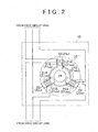
- the electric motor 12 in the embodiment is formed by winding motor coils 21A and 21B of two independent systems around a single stator 22.
- the motor coil 21 A (21 ua, 21 va and 21 wa) of a first one of the two systems and the motor coil 21 B (21 ub, 21vb and 21wb) of a second system are each wound separately for a corresponding one of phases (U, V and W) on a corresponding one of teeth 23 (23u, 23v and 23w) of the stator 22.
- a rotor 24 is rotatably supported.
- the electric motor 12 in the embodiment has the stator 22 and the rotor 24 that are used commonly for the motor coils 21 A and 21B of the two systems.
- the rotor 24 rotates on the basis of the magnetomotive force generated by motor coils 21A and 21B that are wound around the teeth 23 (23u, 23v and 23w).
- the ECU 11 in the embodiment controls the motor torque of the electric motor 12 by supplying drive electric power to the motor coils 21 A and 21B independently of each other.
- the ECU 11 in the embodiment includes two drive circuits 26A and 26B that are provided independently of each other corresponding to the motor coils 21A and 21B, and a microcomputer 27 that outputs control signals Smc_a and Smc_b to the drive circuits 26A and 26B, respectively, independently of each other.
- the drive circuit 26A is connected to the motor coils 21A of the first system via power lines 28A (28ua, 28va and 28wa), and the drive circuit 26B is connected to the motor coils 21B of the second system via power lines 28B (28ub, 28vb and 28wb).
- the control signal Smc_a that the microcomputer 27 outputs is input to the drive circuit 26A
- the control signal Smc_b that the microcomputer 27 outputs is input to the drive circuit 26B.
- each of the drive circuits 26A and 26B employs a well-known PWM inverter made up of three basic units (three arms) each of which includes a pair of switching elements connected in parallel, and which correspond to the three phases and are connected in parallel.
- the control signals Smc_a and Smc_b that the microcomputer 27 outputs define the on-duty ratios of the three phase arms.
- the ECU 11 in the embodiment supplies drive electric power that the drive circuits 26A and 26B output on the basis of the control signals Smc_a and Smc_b to the corresponding motor coils 21A and 21B independently of each other.
- the microcomputer 27 in the embodiment includes a first control signal output portion 31 A as first control signal output means for outputting the control signal Smc_a to the drive circuit 26A of the first system, and a second control signal output portion 31 B as second control signal output means for outputting the control signal Smc_b to the drive circuit 26B of the second system.
- the first control signal output portion 31 A receives input of the steering torque ⁇ and the vehicle speed V detected by the torque senor 14 and the vehicle speed sensor 15.
- the first control signal output portion 31A computes an electric current command value I*_a that corresponds to a target assist force on the basis of the steering torque ⁇ and the vehicle speed V.
- the first control signal output portion 31A also receives input of an actual value I_a of electric current that is passed through the motor coils 21A of the first system and that is detected by the electric current sensors 32A, and an electric motor rotation angle ⁇ m that is detected by an electric motor resolver 33 (see FIG. 3 ).
- the first control signal output portion 31A outputs the control signal Smc_a to the drive circuit 26A of the first system that corresponds to the first control signal output portion 31A, by executing an electric current feedback control of causing the detected actual electric current value I_a to follow the electric current command value I*_a that the first control signal output portion 31 A computes.
- the steering torque ⁇ and the vehicle speed V are input to an assist control portion 35.
- the assist control portion 35 computes the electric current command value I*_a so that greater motor torque, that is, greater assist force, is generated the greater the steering torque ⁇ is and the slower the vehicle speed V is.
- the electric current command value I*_a are input to an electric current control portion 36, together with the actual electric current value I_a detected by the electric current sensors 32A. Then, the electric current control portion 36 executes an electric current feedback computation on the basis of an electric current deviation between the electric current command value I*_a and the actual electric current value I_a.
- electric current sensors 32A (32ua, 32va and 32wa) detect, as the actual electric current value I_a, the phase current values Iu_a, Iv_a and Iw_a of current passed through the motor coils 21 A of the first system. Then, the electric current control portion 36 in the embodiment executes the electric current feedback computation in a d/q coordinate system by converting the phase current values Iu_a, Iv_a and Iw_a into d-axis currents and q-axis current in the d/q coordinate system (d/q conversion).
- the assist control portion 35 in the embodiment computes a q-axis electric current command value as the electric current command value I*_a (the d-axis electric current command value is "0"). Then, the electric current control portion 36 computes a voltage command value V*_a that corresponds to each of the phases of the motor coils 21 A by mapping on a three-phase alternating-current coordinates a voltage command value in the d/q coordinate system obtained through execution of the electric current feedback computation (inverse d/q conversion).
- the first control signal output portion 31 A in the embodiment outputs the control signal Smc_a that a PWM conversion portion 37 generates on the basis of the voltage command value V*_a, to the corresponding drive circuit 26A of the first system.
- the second control signal output portion 31 B receives input of a position command regarding the steering wheel 2, that is, a steering angle command value ⁇ s*, that is input from the superior ECU via the in-vehicle network (CAN: Controller Area Network) 40 (see FIG. 1 ).
- the steering angle command value ⁇ s* is input as a control command for automatically controlling the path of the vehicle and, more specifically, a control command for executing a so-called lane keep assist control, by changing the steering angle of the steering road wheels 7 independently of the steering operation of the driver.
- the second control signal output portion 31B in the embodiment detects the actual steering angle of the steering wheel 2, that is, the steering angle ⁇ s, on the basis of the electric motor rotation angle ⁇ m that is detected by the electric motor resolver 33. Then, the second control signal output portion 31B outputs the control signal Smc_b to the corresponding drive circuit 26B of the second system by executing the position feedback control so as to cause the steering angle ⁇ s detected as the actual steering angle to follow the steering angle command value ⁇ s* input to the second control signal output portion 31B.
- the electric motor rotation angle ⁇ m input to the second control signal output portion 31B is converted into the steering angle ⁇ s by the steering angle computation portion 41.
- the steering angle ⁇ s is input together with the steering angle command value ⁇ s* to a position control portion 42.
- the position control portion 42 executes a position feedback computation on the basis of a positional deviation between the steering angle command value ⁇ s* and the steering angle ⁇ s.
- the second control signal output portion 31B in the embodiment includes a speed control portion 43 and an electric current control portion 44 that form feedback loops of a speed control and an electric current control (torque control), respectively, as minor loops of a position feedback loop that the position control portion 42 forms.
- the position control portion 42 computes a steering angular speed command value ⁇ s* through execution of the position feedback computation
- the speed control portion 43 computes an electric current command value I*_b on the basis of a speed deviation between the steering angular speed command value ⁇ s* and an actual steering angular speed ⁇ s.
- the electric current control portion 44 computes a voltage command value V*_b by executing the electric current feedback computation on the basis of an electric current deviation between the electric current command value I*_b and an actual electric current value I_b that is detected by electric current sensors 32B.
- the manner of the electric current detection performed by the electric current sensors 32B (32ub, 32vb and 32wb) (the detection of the three phase current values Iu_b, Iv_b and Iw_b) and the manner of the electric current feedback computation that the electric current control portion 44 executes are substantially the same as the manner of the electric current detection that the electric current sensors 32A of the first system performs and the manner of the electric current feedback computation that the electric current control portion 36 executes, respectively.
- the second control signal output portion 31 B in the embodiment outputs the control signal Smc_b that the PWM conversion portion 45 generates on the basis of the voltage command value V*_b, to the corresponding drive circuit 26B of the second system.
- the microcomputer 27 in the embodiment outputs the control signals Smc_a and Smc_b to the drive circuits 26A and 26B of the two systems, respectively, independently of each other. Then, as shown in FIG. 5 , the ECU 11 in the embodiment executes an electric current control (torque control) for executing the power assist control, and a position control for executing an automatic control, simultaneously and independently of each other.
- an electric current control torque control
- a position control for executing an automatic control
- L is inductance
- S is a differential operator
- the ECU 11 includes the two drive circuits 26A and 26B provided corresponding to the motor coils 21A and 21B of the two systems independent of each other, and the microcomputer 27 that outputs the independent control signals Smc_a and Smc b of the two systems to the drive circuits 26A and 26B.
- the microcomputer 27 includes the first control signal output portion 31A that outputs the control signal Smc_a to the drive circuit 26A of the first system by executing the electric current control so as to generate the motor torque that corresponds to the assist force.
- the microcomputer 27 also includes the second control signal output portion 31 B that outputs the control signal Smc_b to the drive circuit 26B of the second system by executing the position control on the basis of the steering angle command value ⁇ s* that is input from the superior ECU via the in-vehicle network 40, so as to change the steering angle of the steering road wheels.
- the automatic control such as the lane keep assist control or the like, is realized by controlling the steering angle position.
- the position control such a high response as required in the power assist control (electric current control) is not required. Therefore, as in the foregoing construction, by executing the position control for executing the automatic control independently of the electric current control (torque control) for executing the power assist control, it is possible to optimize the response of the position control without causing a decline in the responsiveness in the power assist control, and therefore to restrain the influence caused by changes of the position command (steering angle command value ⁇ s*). As a result, even in an environment with an external disturbance, it is possible to restrain the disturbance in the locus of travel and smoothly execute the automatic control.
- the EPS actuator 10 uses as a drive source the electric motor 12 that has the stator 22 and the rotor 24 that are common to the motor coils 21A and 21B of the two systems. Therefore, the electric current control (torque control) for executing the power assist control, and the position control for executing the automatic control can be executed simultaneously and independently of each other without increasing the size of the apparatus.
- the second control signal output portion 31B includes the speed control portion 43 and the electric current control portion 44 that form the feedback loops of the speed control and the electric current control (torque control) as minor loops of the position feedback loop that the position control portion 42 forms. Therefore, the automatic control can be executed more smoothly.
- the invention is embodied as the so-called column type EPS 1, the invention may also be applied to a so-called pinion type or rack-assist type EPS.
- the EPS actuator 10 uses as a drive source the electric motor 12 that has the stator 22 and the rotor 24 that are used commonly for the motor coils 21 A and 21B of the two systems.
- this construction is not restrictive, that is, each motor coil may have its own stator or its own rotor.
- the invention is also applicable to a construction that employs two electric motors as drive sources.
- the motor coils of each system may be disposed so as to have a relationship in which the phases of the coils are deviated from each other.
- the invention may also be embodied not only as the EPS but also as an electric motor control system that controls an electric motor that is equipped with motor coils of two systems provided independently of each other.
- the electric motor 12 used is a brushless electric motor in which the motor coils 21A and 21B of the independent two systems are wound on the same stator 22, the invention may also be embodied in a brush-equipped electric motor that includes an armature rotor that has motor coils of two systems.
- the ECU 11 has the two drive circuits 26A and 26B that are provided independently corresponding to the motor coils 21A and 21B.
- the construction in which each system is equipped with a back-up drive circuit, and the like, and the numbers of drive circuits in each system are not particularly limited.
- the feedback loops of the speed control and the electric current control are provided as minor loops of the position feedback loop.
- the minor loops may be changed as appropriate; for example, at least one of the speed feedback loop and the electric current feedback loop may be omitted, or a voltage feedback loop may be added.
- the lane keep assist control is executed as an automatic control.
- the manner of the automatic control may be any manner as long as the control is realized by the position control regarding the steering angle (electric motor rotation angle); for example, the automatic control may be a parking assist control, a control of controlling the steering angle of the steering road wheels so as to control the posture of the vehicle, etc.
- the actual steering angle of the steering wheel 2 that is, the steering angle ⁇ s
- the steering angle ⁇ s is detected on the basis of the electric motor rotation angle ⁇ m detected by the electric motor resolver 33
Landscapes
- Engineering & Computer Science (AREA)
- Chemical & Material Sciences (AREA)
- Combustion & Propulsion (AREA)
- Transportation (AREA)
- Mechanical Engineering (AREA)
- Physics & Mathematics (AREA)
- Mathematical Physics (AREA)
- Steering Control In Accordance With Driving Conditions (AREA)
- Power Steering Mechanism (AREA)
- Control Of Ac Motors In General (AREA)
Claims (3)
- Direction à assistance électrique (1) comprenant un dispositif d'assistance de direction (10) qui délivre une force d'assistance à un système de direction sur la base d'une force magnétomotrice qui est générée par des bobines de moteur (21A, 21B) de deux systèmes qui sont prévus indépendamment l'un de l'autre, et des moyens de commande (11) destinés à commander le fonctionnement du dispositif d'assistance de direction par l'intermédiaire de l'alimentation en énergie électrique des bobines de moteur, la direction à assistance électrique étant caractérisée en ce que :les moyens de commande comprennent un circuit de commande (26A) d'un premier système et un circuit de commande (26B) d'un deuxième système qui sont prévus indépendamment l'un de l'autre en correspondance avec les bobines de moteur ;les moyens de commande (11) comprennent des premiers moyens de sortie de signal de commande (31A) destinés à délivrer un signal de commande au circuit de commande du premier système en exécutant une commande de courant électrique de façon à générer un couple de moteur qui correspond à la force d'assistance ; etles moyens de commande (11) comprennent des deuxièmes moyens de sortie de signal de commande (31B) destinés à délivrer un signal de commande au circuit de commande du deuxième système en exécutant une commande de position sur la base d'une commande de position qui est entrée de façon à changer l'angle de braquage d'une roue directrice,le dispositif d'assistance de direction (10) utilisant, comme source d'entraînement, un moteur électrique (12) qui comprend un stator (22) et un rotor (24) qui sont utilisés en commun pour les bobines de moteur (21A, 21B).
- Direction à assistance électrique selon la revendication 1, dans laquelle le moteur électrique (12) est un moteur électrique sans balai.
- Direction à assistance électrique selon la revendication 1 ou 2, dans laquelle les moyens de commande (11) exécutent une boucle de rétroaction de position de la commande de position, et exécutent, comme petite boucle de la boucle de rétroaction de position, une boucle de rétroaction d'au moins une d'une commande de vitesse, d'une commande de courant électrique et d'une commande de tension.
Applications Claiming Priority (2)
| Application Number | Priority Date | Filing Date | Title |
|---|---|---|---|
| JP2010200282A JP5569273B2 (ja) | 2010-09-07 | 2010-09-07 | 電動パワーステアリング装置 |
| PCT/IB2011/002059 WO2012032395A1 (fr) | 2010-09-07 | 2011-09-06 | Appareil de direction à assistance électrique |
Publications (2)
| Publication Number | Publication Date |
|---|---|
| EP2613993A1 EP2613993A1 (fr) | 2013-07-17 |
| EP2613993B1 true EP2613993B1 (fr) | 2014-12-24 |
Family
ID=44913353
Family Applications (1)
| Application Number | Title | Priority Date | Filing Date |
|---|---|---|---|
| EP11779849.6A Not-in-force EP2613993B1 (fr) | 2010-09-07 | 2011-09-06 | Direction assistee electrique |
Country Status (5)
| Country | Link |
|---|---|
| US (1) | US8996252B2 (fr) |
| EP (1) | EP2613993B1 (fr) |
| JP (1) | JP5569273B2 (fr) |
| CN (1) | CN103079933B (fr) |
| WO (1) | WO2012032395A1 (fr) |
Families Citing this family (10)
| Publication number | Priority date | Publication date | Assignee | Title |
|---|---|---|---|---|
| JP2013071550A (ja) * | 2011-09-27 | 2013-04-22 | Jtekt Corp | 車両操舵装置の制御装置 |
| JP6036538B2 (ja) * | 2013-05-15 | 2016-11-30 | 株式会社ジェイテクト | 電動パワーステアリング装置 |
| US10507866B2 (en) | 2015-05-11 | 2019-12-17 | Thyssenkrupp Presta Ag | Electric power steering system with ripple compensation |
| JP6627261B2 (ja) * | 2015-05-20 | 2020-01-08 | 株式会社ジェイテクト | 自動操舵装置 |
| JP6588571B2 (ja) * | 2016-01-13 | 2019-10-09 | 日立オートモティブシステムズ株式会社 | 操舵装置 |
| CN107117205B (zh) * | 2017-05-11 | 2018-12-14 | 安徽江淮汽车集团股份有限公司 | 一种具有故障诊断的电动助力转向系统 |
| JP7183730B2 (ja) * | 2018-02-05 | 2022-12-06 | 株式会社デンソー | 操舵制御装置 |
| CN110228524B (zh) * | 2018-03-06 | 2021-09-14 | 重庆邮电大学 | 基于多层模糊控制的无人车辆自动转向控制方法 |
| JP7376407B2 (ja) * | 2020-03-27 | 2023-11-08 | 株式会社ジェイテクト | 操舵制御装置 |
| WO2023112133A1 (fr) | 2021-12-14 | 2023-06-22 | 三菱電機株式会社 | Dispositif de direction assistée électrique |
Family Cites Families (26)
| Publication number | Priority date | Publication date | Assignee | Title |
|---|---|---|---|---|
| DE19837340B4 (de) | 1998-08-18 | 2005-12-29 | Daimlerchrysler Ag | Lenksystem in einem mit einer Spurfolgeeinrichtung ausgestatteten Fahrzeug |
| JP2001341658A (ja) * | 2000-03-29 | 2001-12-11 | Toyoda Mach Works Ltd | 電動パワーステアリング装置の制御装置 |
| JP3567866B2 (ja) * | 2000-07-31 | 2004-09-22 | トヨタ自動車株式会社 | 車両の操舵支援装置 |
| JP2003040123A (ja) * | 2001-07-27 | 2003-02-13 | Koyo Seiko Co Ltd | 電動パワーステアリング装置 |
| JP3839358B2 (ja) * | 2002-06-12 | 2006-11-01 | 株式会社ジェイテクト | 車両の操舵制御装置及び車両の操舵制御方法 |
| US7014008B2 (en) * | 2002-06-27 | 2006-03-21 | Honda Giken Kogyo Kabushiki Kaisha | Steering system for vehicle |
| JP4120427B2 (ja) * | 2003-03-06 | 2008-07-16 | トヨタ自動車株式会社 | 車輌用操舵制御装置 |
| JP4378998B2 (ja) | 2003-05-21 | 2009-12-09 | 三菱自動車工業株式会社 | パワーステアリング装置 |
| CN100436227C (zh) * | 2003-10-02 | 2008-11-26 | 日产自动车株式会社 | 车辆转向装置 |
| JP2005176477A (ja) * | 2003-12-10 | 2005-06-30 | Favess Co Ltd | モータ制御装置およびそれを用いた車両用操舵装置 |
| CN100490302C (zh) * | 2004-03-19 | 2009-05-20 | 三菱电机株式会社 | 电动机控制装置 |
| JP4175293B2 (ja) | 2004-06-01 | 2008-11-05 | トヨタ自動車株式会社 | 車両用操舵支援装置 |
| JP4617946B2 (ja) * | 2005-03-22 | 2011-01-26 | 株式会社ジェイテクト | 車両用操舵装置 |
| JP4509841B2 (ja) * | 2005-03-29 | 2010-07-21 | 株式会社ショーワ | 電動パワーステアリング装置 |
| WO2006132268A1 (fr) * | 2005-06-07 | 2006-12-14 | Jtekt Corporation | Dispositif de direction assistée électrique |
| US20090240389A1 (en) * | 2006-05-31 | 2009-09-24 | Nsk Ltd | Electric power steering apparatus |
| JP5470697B2 (ja) * | 2007-06-20 | 2014-04-16 | 株式会社ジェイテクト | 電動パワーステアリング装置 |
| JP4623063B2 (ja) * | 2007-08-02 | 2011-02-02 | 株式会社デンソー | 操舵補助装置 |
| JP5166820B2 (ja) * | 2007-10-19 | 2013-03-21 | 本田技研工業株式会社 | ステアリング装置 |
| JP5136013B2 (ja) * | 2007-11-16 | 2013-02-06 | 株式会社ジェイテクト | 電動パワーステアリング装置 |
| JP2009269540A (ja) * | 2008-05-09 | 2009-11-19 | Jtekt Corp | 電動パワーステアリング装置 |
| JP4631928B2 (ja) * | 2008-05-12 | 2011-02-16 | トヨタ自動車株式会社 | 車両のステアリング装置 |
| US20100072738A1 (en) * | 2008-09-19 | 2010-03-25 | Trw Automotive U.S. Llc | Steering System |
| JP5526630B2 (ja) * | 2009-07-08 | 2014-06-18 | 株式会社ジェイテクト | 電動パワーステアリング装置 |
| JP5563077B2 (ja) * | 2010-06-18 | 2014-07-30 | 日立オートモティブシステムズ株式会社 | 電子制御装置 |
| JP5051404B2 (ja) * | 2010-08-25 | 2012-10-17 | トヨタ自動車株式会社 | トルク検出装置 |
-
2010
- 2010-09-07 JP JP2010200282A patent/JP5569273B2/ja not_active Expired - Fee Related
-
2011
- 2011-09-06 CN CN201180042566.5A patent/CN103079933B/zh not_active Expired - Fee Related
- 2011-09-06 EP EP11779849.6A patent/EP2613993B1/fr not_active Not-in-force
- 2011-09-06 US US13/818,260 patent/US8996252B2/en not_active Expired - Fee Related
- 2011-09-06 WO PCT/IB2011/002059 patent/WO2012032395A1/fr active Application Filing
Also Published As
| Publication number | Publication date |
|---|---|
| CN103079933A (zh) | 2013-05-01 |
| US20130173118A1 (en) | 2013-07-04 |
| JP2012056404A (ja) | 2012-03-22 |
| CN103079933B (zh) | 2016-07-06 |
| WO2012032395A1 (fr) | 2012-03-15 |
| US8996252B2 (en) | 2015-03-31 |
| EP2613993A1 (fr) | 2013-07-17 |
| JP5569273B2 (ja) | 2014-08-13 |
Similar Documents
| Publication | Publication Date | Title |
|---|---|---|
| EP2613993B1 (fr) | Direction assistee electrique | |
| EP2625088B1 (fr) | Équipement de direction assistée électrique | |
| JP5672936B2 (ja) | 電動パワーステアリング装置 | |
| WO2013069473A1 (fr) | Dispositif de direction assistée actionné électriquement | |
| EP2614007B1 (fr) | Système de direction électrique | |
| WO2015129271A1 (fr) | Dispositif de commande de moteur et dispositif de servo-direction électrique et véhicule utilisant ledit dispositif de commande de moteur | |
| EP2210795B1 (fr) | Appareil de direction assistée électrique | |
| US20180287538A1 (en) | Control apparatus for multi-phase rotating electric machine | |
| US11081981B2 (en) | Rotating machine controller | |
| EP2621789B1 (fr) | Appareil de servodirection électrique | |
| JP2013159165A (ja) | 電動パワーステアリング装置 | |
| JP2017226305A (ja) | 電動パワーステアリング装置 | |
| EP2567879B1 (fr) | Système de direction assistée électrique | |
| JP4644013B2 (ja) | 電動パワーステアリング装置 | |
| JP2012147531A (ja) | 電動パワーステアリング装置 | |
| JP5719177B2 (ja) | 電動パワーステアリング装置 | |
| JP2009046005A (ja) | 電気式動力舵取装置 | |
| JP5699527B2 (ja) | 電動パワーステアリング装置 | |
| JP2013005624A (ja) | 車両用操舵装置 | |
| JP2013023002A (ja) | 電動パワーステアリング装置 | |
| JP2012076644A (ja) | 電動パワーステアリング装置 | |
| JP2005160221A (ja) | 電動パワーステアリング装置の制御装置 | |
| JP5131435B2 (ja) | 電動パワーステアリング装置 | |
| JP2014043163A (ja) | 電動パワーステアリング装置 |
Legal Events
| Date | Code | Title | Description |
|---|---|---|---|
| PUAI | Public reference made under article 153(3) epc to a published international application that has entered the european phase |
Free format text: ORIGINAL CODE: 0009012 |
|
| 17P | Request for examination filed |
Effective date: 20130226 |
|
| AK | Designated contracting states |
Kind code of ref document: A1 Designated state(s): AL AT BE BG CH CY CZ DE DK EE ES FI FR GB GR HR HU IE IS IT LI LT LU LV MC MK MT NL NO PL PT RO RS SE SI SK SM TR |
|
| DAX | Request for extension of the european patent (deleted) | ||
| 17Q | First examination report despatched |
Effective date: 20131121 |
|
| GRAP | Despatch of communication of intention to grant a patent |
Free format text: ORIGINAL CODE: EPIDOSNIGR1 |
|
| INTG | Intention to grant announced |
Effective date: 20140701 |
|
| GRAS | Grant fee paid |
Free format text: ORIGINAL CODE: EPIDOSNIGR3 |
|
| RIN1 | Information on inventor provided before grant (corrected) |
Inventor name: SUZUKI, HIROSHI |
|
| GRAA | (expected) grant |
Free format text: ORIGINAL CODE: 0009210 |
|
| AK | Designated contracting states |
Kind code of ref document: B1 Designated state(s): AL AT BE BG CH CY CZ DE DK EE ES FI FR GB GR HR HU IE IS IT LI LT LU LV MC MK MT NL NO PL PT RO RS SE SI SK SM TR |
|
| RAP1 | Party data changed (applicant data changed or rights of an application transferred) |
Owner name: JTEKT CORPORATION |
|
| REG | Reference to a national code |
Ref country code: GB Ref legal event code: FG4D |
|
| RIN1 | Information on inventor provided before grant (corrected) |
Inventor name: SUZUKI, HIROSHI |
|
| REG | Reference to a national code |
Ref country code: CH Ref legal event code: EP |
|
| REG | Reference to a national code |
Ref country code: IE Ref legal event code: FG4D |
|
| REG | Reference to a national code |
Ref country code: AT Ref legal event code: REF Ref document number: 702972 Country of ref document: AT Kind code of ref document: T Effective date: 20150115 |
|
| REG | Reference to a national code |
Ref country code: DE Ref legal event code: R096 Ref document number: 602011012587 Country of ref document: DE Effective date: 20150219 |
|
| REG | Reference to a national code |
Ref country code: NL Ref legal event code: VDEP Effective date: 20141224 |
|
| PG25 | Lapsed in a contracting state [announced via postgrant information from national office to epo] |
Ref country code: LT Free format text: LAPSE BECAUSE OF FAILURE TO SUBMIT A TRANSLATION OF THE DESCRIPTION OR TO PAY THE FEE WITHIN THE PRESCRIBED TIME-LIMIT Effective date: 20141224 Ref country code: FI Free format text: LAPSE BECAUSE OF FAILURE TO SUBMIT A TRANSLATION OF THE DESCRIPTION OR TO PAY THE FEE WITHIN THE PRESCRIBED TIME-LIMIT Effective date: 20141224 Ref country code: NO Free format text: LAPSE BECAUSE OF FAILURE TO SUBMIT A TRANSLATION OF THE DESCRIPTION OR TO PAY THE FEE WITHIN THE PRESCRIBED TIME-LIMIT Effective date: 20150324 |
|
| REG | Reference to a national code |
Ref country code: LT Ref legal event code: MG4D |
|
| PG25 | Lapsed in a contracting state [announced via postgrant information from national office to epo] |
Ref country code: GR Free format text: LAPSE BECAUSE OF FAILURE TO SUBMIT A TRANSLATION OF THE DESCRIPTION OR TO PAY THE FEE WITHIN THE PRESCRIBED TIME-LIMIT Effective date: 20150325 Ref country code: LV Free format text: LAPSE BECAUSE OF FAILURE TO SUBMIT A TRANSLATION OF THE DESCRIPTION OR TO PAY THE FEE WITHIN THE PRESCRIBED TIME-LIMIT Effective date: 20141224 Ref country code: HR Free format text: LAPSE BECAUSE OF FAILURE TO SUBMIT A TRANSLATION OF THE DESCRIPTION OR TO PAY THE FEE WITHIN THE PRESCRIBED TIME-LIMIT Effective date: 20141224 Ref country code: RS Free format text: LAPSE BECAUSE OF FAILURE TO SUBMIT A TRANSLATION OF THE DESCRIPTION OR TO PAY THE FEE WITHIN THE PRESCRIBED TIME-LIMIT Effective date: 20141224 Ref country code: SE Free format text: LAPSE BECAUSE OF FAILURE TO SUBMIT A TRANSLATION OF THE DESCRIPTION OR TO PAY THE FEE WITHIN THE PRESCRIBED TIME-LIMIT Effective date: 20141224 |
|
| REG | Reference to a national code |
Ref country code: AT Ref legal event code: MK05 Ref document number: 702972 Country of ref document: AT Kind code of ref document: T Effective date: 20141224 |
|
| PG25 | Lapsed in a contracting state [announced via postgrant information from national office to epo] |
Ref country code: NL Free format text: LAPSE BECAUSE OF FAILURE TO SUBMIT A TRANSLATION OF THE DESCRIPTION OR TO PAY THE FEE WITHIN THE PRESCRIBED TIME-LIMIT Effective date: 20141224 |
|
| PG25 | Lapsed in a contracting state [announced via postgrant information from national office to epo] |
Ref country code: EE Free format text: LAPSE BECAUSE OF FAILURE TO SUBMIT A TRANSLATION OF THE DESCRIPTION OR TO PAY THE FEE WITHIN THE PRESCRIBED TIME-LIMIT Effective date: 20141224 Ref country code: SK Free format text: LAPSE BECAUSE OF FAILURE TO SUBMIT A TRANSLATION OF THE DESCRIPTION OR TO PAY THE FEE WITHIN THE PRESCRIBED TIME-LIMIT Effective date: 20141224 Ref country code: RO Free format text: LAPSE BECAUSE OF FAILURE TO SUBMIT A TRANSLATION OF THE DESCRIPTION OR TO PAY THE FEE WITHIN THE PRESCRIBED TIME-LIMIT Effective date: 20141224 Ref country code: CZ Free format text: LAPSE BECAUSE OF FAILURE TO SUBMIT A TRANSLATION OF THE DESCRIPTION OR TO PAY THE FEE WITHIN THE PRESCRIBED TIME-LIMIT Effective date: 20141224 Ref country code: ES Free format text: LAPSE BECAUSE OF FAILURE TO SUBMIT A TRANSLATION OF THE DESCRIPTION OR TO PAY THE FEE WITHIN THE PRESCRIBED TIME-LIMIT Effective date: 20141224 |
|
| PG25 | Lapsed in a contracting state [announced via postgrant information from national office to epo] |
Ref country code: PL Free format text: LAPSE BECAUSE OF FAILURE TO SUBMIT A TRANSLATION OF THE DESCRIPTION OR TO PAY THE FEE WITHIN THE PRESCRIBED TIME-LIMIT Effective date: 20141224 Ref country code: IS Free format text: LAPSE BECAUSE OF FAILURE TO SUBMIT A TRANSLATION OF THE DESCRIPTION OR TO PAY THE FEE WITHIN THE PRESCRIBED TIME-LIMIT Effective date: 20150424 Ref country code: AT Free format text: LAPSE BECAUSE OF FAILURE TO SUBMIT A TRANSLATION OF THE DESCRIPTION OR TO PAY THE FEE WITHIN THE PRESCRIBED TIME-LIMIT Effective date: 20141224 |
|
| REG | Reference to a national code |
Ref country code: DE Ref legal event code: R097 Ref document number: 602011012587 Country of ref document: DE |
|
| PG25 | Lapsed in a contracting state [announced via postgrant information from national office to epo] |
Ref country code: DK Free format text: LAPSE BECAUSE OF FAILURE TO SUBMIT A TRANSLATION OF THE DESCRIPTION OR TO PAY THE FEE WITHIN THE PRESCRIBED TIME-LIMIT Effective date: 20141224 |
|
| PLBE | No opposition filed within time limit |
Free format text: ORIGINAL CODE: 0009261 |
|
| STAA | Information on the status of an ep patent application or granted ep patent |
Free format text: STATUS: NO OPPOSITION FILED WITHIN TIME LIMIT |
|
| 26N | No opposition filed |
Effective date: 20150925 |
|
| PG25 | Lapsed in a contracting state [announced via postgrant information from national office to epo] |
Ref country code: IT Free format text: LAPSE BECAUSE OF FAILURE TO SUBMIT A TRANSLATION OF THE DESCRIPTION OR TO PAY THE FEE WITHIN THE PRESCRIBED TIME-LIMIT Effective date: 20141224 |
|
| PG25 | Lapsed in a contracting state [announced via postgrant information from national office to epo] |
Ref country code: SI Free format text: LAPSE BECAUSE OF FAILURE TO SUBMIT A TRANSLATION OF THE DESCRIPTION OR TO PAY THE FEE WITHIN THE PRESCRIBED TIME-LIMIT Effective date: 20141224 |
|
| PG25 | Lapsed in a contracting state [announced via postgrant information from national office to epo] |
Ref country code: MC Free format text: LAPSE BECAUSE OF FAILURE TO SUBMIT A TRANSLATION OF THE DESCRIPTION OR TO PAY THE FEE WITHIN THE PRESCRIBED TIME-LIMIT Effective date: 20141224 Ref country code: LU Free format text: LAPSE BECAUSE OF FAILURE TO SUBMIT A TRANSLATION OF THE DESCRIPTION OR TO PAY THE FEE WITHIN THE PRESCRIBED TIME-LIMIT Effective date: 20150906 |
|
| REG | Reference to a national code |
Ref country code: CH Ref legal event code: PL |
|
| GBPC | Gb: european patent ceased through non-payment of renewal fee |
Effective date: 20150906 |
|
| PG25 | Lapsed in a contracting state [announced via postgrant information from national office to epo] |
Ref country code: BE Free format text: LAPSE BECAUSE OF FAILURE TO SUBMIT A TRANSLATION OF THE DESCRIPTION OR TO PAY THE FEE WITHIN THE PRESCRIBED TIME-LIMIT Effective date: 20141224 |
|
| REG | Reference to a national code |
Ref country code: IE Ref legal event code: MM4A |
|
| PG25 | Lapsed in a contracting state [announced via postgrant information from national office to epo] |
Ref country code: CH Free format text: LAPSE BECAUSE OF NON-PAYMENT OF DUE FEES Effective date: 20150930 Ref country code: IE Free format text: LAPSE BECAUSE OF NON-PAYMENT OF DUE FEES Effective date: 20150906 Ref country code: LI Free format text: LAPSE BECAUSE OF NON-PAYMENT OF DUE FEES Effective date: 20150930 Ref country code: GB Free format text: LAPSE BECAUSE OF NON-PAYMENT OF DUE FEES Effective date: 20150906 |
|
| REG | Reference to a national code |
Ref country code: FR Ref legal event code: PLFP Year of fee payment: 6 |
|
| PG25 | Lapsed in a contracting state [announced via postgrant information from national office to epo] |
Ref country code: MT Free format text: LAPSE BECAUSE OF FAILURE TO SUBMIT A TRANSLATION OF THE DESCRIPTION OR TO PAY THE FEE WITHIN THE PRESCRIBED TIME-LIMIT Effective date: 20141224 |
|
| PG25 | Lapsed in a contracting state [announced via postgrant information from national office to epo] |
Ref country code: HU Free format text: LAPSE BECAUSE OF FAILURE TO SUBMIT A TRANSLATION OF THE DESCRIPTION OR TO PAY THE FEE WITHIN THE PRESCRIBED TIME-LIMIT; INVALID AB INITIO Effective date: 20110906 Ref country code: BG Free format text: LAPSE BECAUSE OF FAILURE TO SUBMIT A TRANSLATION OF THE DESCRIPTION OR TO PAY THE FEE WITHIN THE PRESCRIBED TIME-LIMIT Effective date: 20141224 Ref country code: SM Free format text: LAPSE BECAUSE OF FAILURE TO SUBMIT A TRANSLATION OF THE DESCRIPTION OR TO PAY THE FEE WITHIN THE PRESCRIBED TIME-LIMIT Effective date: 20141224 |
|
| PG25 | Lapsed in a contracting state [announced via postgrant information from national office to epo] |
Ref country code: CY Free format text: LAPSE BECAUSE OF FAILURE TO SUBMIT A TRANSLATION OF THE DESCRIPTION OR TO PAY THE FEE WITHIN THE PRESCRIBED TIME-LIMIT Effective date: 20141224 |
|
| REG | Reference to a national code |
Ref country code: FR Ref legal event code: PLFP Year of fee payment: 7 |
|
| PG25 | Lapsed in a contracting state [announced via postgrant information from national office to epo] |
Ref country code: MK Free format text: LAPSE BECAUSE OF FAILURE TO SUBMIT A TRANSLATION OF THE DESCRIPTION OR TO PAY THE FEE WITHIN THE PRESCRIBED TIME-LIMIT Effective date: 20141224 Ref country code: TR Free format text: LAPSE BECAUSE OF FAILURE TO SUBMIT A TRANSLATION OF THE DESCRIPTION OR TO PAY THE FEE WITHIN THE PRESCRIBED TIME-LIMIT Effective date: 20141224 |
|
| PG25 | Lapsed in a contracting state [announced via postgrant information from national office to epo] |
Ref country code: PT Free format text: LAPSE BECAUSE OF FAILURE TO SUBMIT A TRANSLATION OF THE DESCRIPTION OR TO PAY THE FEE WITHIN THE PRESCRIBED TIME-LIMIT Effective date: 20141224 |
|
| REG | Reference to a national code |
Ref country code: FR Ref legal event code: PLFP Year of fee payment: 8 |
|
| PG25 | Lapsed in a contracting state [announced via postgrant information from national office to epo] |
Ref country code: AL Free format text: LAPSE BECAUSE OF FAILURE TO SUBMIT A TRANSLATION OF THE DESCRIPTION OR TO PAY THE FEE WITHIN THE PRESCRIBED TIME-LIMIT Effective date: 20141224 |
|
| PGFP | Annual fee paid to national office [announced via postgrant information from national office to epo] |
Ref country code: FR Payment date: 20210812 Year of fee payment: 11 |
|
| PGFP | Annual fee paid to national office [announced via postgrant information from national office to epo] |
Ref country code: DE Payment date: 20210727 Year of fee payment: 11 |
|
| REG | Reference to a national code |
Ref country code: DE Ref legal event code: R119 Ref document number: 602011012587 Country of ref document: DE |
|
| PG25 | Lapsed in a contracting state [announced via postgrant information from national office to epo] |
Ref country code: FR Free format text: LAPSE BECAUSE OF NON-PAYMENT OF DUE FEES Effective date: 20220930 Ref country code: DE Free format text: LAPSE BECAUSE OF NON-PAYMENT OF DUE FEES Effective date: 20230401 |