EP2585735B1 - Pneumatische verzögerungsvorrichtung mit konstanter leistung - Google Patents
Pneumatische verzögerungsvorrichtung mit konstanter leistung Download PDFInfo
- Publication number
- EP2585735B1 EP2585735B1 EP11809297.2A EP11809297A EP2585735B1 EP 2585735 B1 EP2585735 B1 EP 2585735B1 EP 11809297 A EP11809297 A EP 11809297A EP 2585735 B1 EP2585735 B1 EP 2585735B1
- Authority
- EP
- European Patent Office
- Prior art keywords
- piston
- piston rod
- cylinder
- space
- deceleration device
- Prior art date
- Legal status (The legal status is an assumption and is not a legal conclusion. Google has not performed a legal analysis and makes no representation as to the accuracy of the status listed.)
- Active
Links
Images
Classifications
-
- F—MECHANICAL ENGINEERING; LIGHTING; HEATING; WEAPONS; BLASTING
- F16—ENGINEERING ELEMENTS AND UNITS; GENERAL MEASURES FOR PRODUCING AND MAINTAINING EFFECTIVE FUNCTIONING OF MACHINES OR INSTALLATIONS; THERMAL INSULATION IN GENERAL
- F16F—SPRINGS; SHOCK-ABSORBERS; MEANS FOR DAMPING VIBRATION
- F16F9/00—Springs, vibration-dampers, shock-absorbers, or similarly-constructed movement-dampers using a fluid or the equivalent as damping medium
- F16F9/32—Details
- F16F9/36—Special sealings, including sealings or guides for piston-rods
- F16F9/368—Sealings in pistons
-
- E—FIXED CONSTRUCTIONS
- E05—LOCKS; KEYS; WINDOW OR DOOR FITTINGS; SAFES
- E05F—DEVICES FOR MOVING WINGS INTO OPEN OR CLOSED POSITION; CHECKS FOR WINGS; WING FITTINGS NOT OTHERWISE PROVIDED FOR, CONCERNED WITH THE FUNCTIONING OF THE WING
- E05F3/00—Closers or openers with braking devices, e.g. checks; Construction of pneumatic or liquid braking devices
- E05F3/02—Closers or openers with braking devices, e.g. checks; Construction of pneumatic or liquid braking devices with pneumatic piston brakes
-
- F—MECHANICAL ENGINEERING; LIGHTING; HEATING; WEAPONS; BLASTING
- F16—ENGINEERING ELEMENTS AND UNITS; GENERAL MEASURES FOR PRODUCING AND MAINTAINING EFFECTIVE FUNCTIONING OF MACHINES OR INSTALLATIONS; THERMAL INSULATION IN GENERAL
- F16F—SPRINGS; SHOCK-ABSORBERS; MEANS FOR DAMPING VIBRATION
- F16F9/00—Springs, vibration-dampers, shock-absorbers, or similarly-constructed movement-dampers using a fluid or the equivalent as damping medium
- F16F9/02—Springs, vibration-dampers, shock-absorbers, or similarly-constructed movement-dampers using a fluid or the equivalent as damping medium using gas only or vacuum
- F16F9/0209—Telescopic
- F16F9/0218—Mono-tubular units
-
- F—MECHANICAL ENGINEERING; LIGHTING; HEATING; WEAPONS; BLASTING
- F16—ENGINEERING ELEMENTS AND UNITS; GENERAL MEASURES FOR PRODUCING AND MAINTAINING EFFECTIVE FUNCTIONING OF MACHINES OR INSTALLATIONS; THERMAL INSULATION IN GENERAL
- F16F—SPRINGS; SHOCK-ABSORBERS; MEANS FOR DAMPING VIBRATION
- F16F9/00—Springs, vibration-dampers, shock-absorbers, or similarly-constructed movement-dampers using a fluid or the equivalent as damping medium
- F16F9/32—Details
- F16F9/3207—Constructional features
- F16F9/3221—Constructional features of piston rods
-
- F—MECHANICAL ENGINEERING; LIGHTING; HEATING; WEAPONS; BLASTING
- F16—ENGINEERING ELEMENTS AND UNITS; GENERAL MEASURES FOR PRODUCING AND MAINTAINING EFFECTIVE FUNCTIONING OF MACHINES OR INSTALLATIONS; THERMAL INSULATION IN GENERAL
- F16F—SPRINGS; SHOCK-ABSORBERS; MEANS FOR DAMPING VIBRATION
- F16F9/00—Springs, vibration-dampers, shock-absorbers, or similarly-constructed movement-dampers using a fluid or the equivalent as damping medium
- F16F9/32—Details
- F16F9/43—Filling or drainage arrangements, e.g. for supply of gas
- F16F9/432—Filling or drainage arrangements, e.g. for supply of gas via piston rod sealing or guiding means
-
- F—MECHANICAL ENGINEERING; LIGHTING; HEATING; WEAPONS; BLASTING
- F16—ENGINEERING ELEMENTS AND UNITS; GENERAL MEASURES FOR PRODUCING AND MAINTAINING EFFECTIVE FUNCTIONING OF MACHINES OR INSTALLATIONS; THERMAL INSULATION IN GENERAL
- F16F—SPRINGS; SHOCK-ABSORBERS; MEANS FOR DAMPING VIBRATION
- F16F9/00—Springs, vibration-dampers, shock-absorbers, or similarly-constructed movement-dampers using a fluid or the equivalent as damping medium
- F16F9/32—Details
- F16F9/50—Special means providing automatic damping adjustment, i.e. self-adjustment of damping by particular sliding movements of a valve element, other than flexions or displacement of valve discs; Special means providing self-adjustment of spring characteristics
- F16F9/516—Special means providing automatic damping adjustment, i.e. self-adjustment of damping by particular sliding movements of a valve element, other than flexions or displacement of valve discs; Special means providing self-adjustment of spring characteristics resulting in the damping effects during contraction being different from the damping effects during extension, i.e. responsive to the direction of movement
Definitions
- the invention relates to a pneumatic deceleration device with a cylinder and with a guided in this by means of a piston rod seal with a pointing in the direction of a piston rod head sealing piston rod, equipped with at least one piston sealing element, a displacement chamber delimiting a compensation chamber piston by positive pressure in the displacement chamber and negative pressure in the expansion chamber builds up a force opposing the stroke movement of the piston, wherein the leakage flow between the displacement chamber and the compensation chamber is at least stroke direction-dependent and wherein the piston sealing element hermetically isolates the displacement chamber and the compensation chamber from one another during pressure build-up in the displacement chamber.
- the compensation chamber is constantly connected via air inlet openings or a through opening with the environment. A negative pressure can not be generated this way.
- the present invention is therefore based on the object to develop a pneumatic deceleration device which has a small spread of the deceleration forces.
- the delay device in the Kolbenendlage the maximum displacement space on a closable pneumatic connection, so that communicate in this end position of the displacement chamber and the compensation chamber by means of this connection with the environment.
- the piston rod seal seals the cylinder interior hermetically against the environment in order to generate the negative pressure in the compensation chamber.
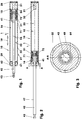
- the Figures 1 - 4 show a delay device (10), which is used for example in a guide system not shown here.
- This guide system carries and carries, for example, a drawer of a piece of furniture. It includes, in addition to the delay device (10), for example, a collection device.
- a collection device For example, when inserting the drawer surrounds before reaching the end position arranged on the drawer delay device (10) fixed in the piece of furniture driver. The lifting movement of the drawer relative to the piece of furniture is delayed.
- the collection device is triggered by means of the drawer.
- the feeder pulls against the action of the delay device (10) the drawer in the example closed end position.
- the delay device (10) remains in this case, for example, until reaching the end position in engagement with the driver.
- the use of a pneumatic retarding device (10) without a retraction device is also conceivable.
- the retarding device (10) comprises a cylinder (21) in which a piston unit (41) consisting of a piston (51) and a piston rod (42) is guided.
- the piston (51) carries two piston sealing elements (71, 72).
- the piston rod head (43) of e.g. largely cylindrical piston rod (42) is formed in this embodiment as a ball head (43). At this ball head (43), a driving element, a stop plate, etc. can be connected.
- the cylinder (21) comprises a pot-shaped cylinder jacket (22) with an integrated cylinder base (28) and a head part (29) closed by means of a piston rod seal (62). It is, for example, as injection molded thermoplastic parts, e.g. Polyoxymethylene, produced.
- the cylinder jacket (22) is cylindrical here on its outer side. Its length is for example five and a half times the diameter.
- the non-cylindrical cylinder inner wall (23) is e.g. formed in the shape of a truncated cone. The larger cross-sectional area of this truncated cone shell is located on the head part (29) of the cylinder (21), the smaller cross-sectional area on the cylinder bottom (28). The former cross-sectional area is e.g. 63 square millimeters. The slope of this Entformungskegels is for example 1:65.
- the inner wall (23) is optionally polished.
- the minimum wall thickness of the cylinder jacket (22) is e.g. 7% of its
- the cylinder bottom (28) has a frustoconical punch (31) projecting into the cylinder interior (25) and having a punch face (32). This limits together with the inner wall an annulus (33).
- the cross-sectional area of the annulus (33) is 80% of the larger cross-sectional area of the truncated cone shell. Its length is, for example, one-seventh of the piston stroke.
- the cylinder (21) can also be designed without a punch (31).
- a longitudinal groove (24) is arranged, see. FIG. 4 ,
- Their length is for example 60% of the cylinder length and ends depending on the design of the cylinder (21) in the plane of the punch face (32) or on the cylinder base (28).
- Their width is for example 2% of the larger diameter of the cylinder inner wall (23).
- the depth of the groove (24) is in this embodiment, a quarter of its width.
- the groove (24) is sharp-edged to the inner wall (23), the Nutauslauf has, for example, a slope of 45 degrees.
- a single groove (24) and a plurality of grooves (24) on the inner wall (23) may be arranged. These can also, for example, helically along the inner wall (23) of the cylinder jacket (22) along.
- the piston rod seal (62) has an outer support ring (63) and an inner sealing lip (64). It forms the piston rod leadthrough (61).
- the support ring (63) is non-sealingly against the piston rod (42).
- the outwardly facing sealing lip (64) engages around the piston rod (42) and seals in the in the FIG. 1 shown retracted piston position the cylinder interior (25) hermetically against the environment (1).
- a non-sealing stop ring (66) is oriented in the direction of the cylinder interior (25).
- the piston (51) and the piston rod (42) of the piston unit (41) are, for example, positively and materially connected to each other, they can be glued together.
- the overall length of the piston unit (41) is e.g. 5% longer than the length of the cylinder (21).
- the cross-sectional area of the piston rod (42), which is made of plastic for example, is one eighth of the internal cross section of the cylinder (21) on the cylinder head (29).
- the piston rod (42) may be bendable.
- the two piston sealing elements (71, 72) are arranged between a stop shoulder (45) of the piston unit (41) and a collar disk (56) oriented to the displacement space (15).
- the first piston sealing element (71) is cup-shaped. It sits firmly with a clamping area (73) between the piston rod (42) and the piston (51).
- An at least approximately cylindrical jacket-shaped collar region (74) adjoins this clamping region (73) and forms a deformation region (74).
- An inwardly projecting support ring (75) limits this piston sealing element (71) in the longitudinal direction (19). This support ring (75) is guided in a circumferential piston recess (52).
- the second sealing element (72) sits in the representation of FIG. 4 spaced from the first sealing element (71) in the piston recess (52). This is a direction in the direction of the displacement chamber (15) opened shaft seal (72) with an outer sealing collar (76).
- the piston sealing elements (71, 72) are made, for example, from nitrile butadiene rubber with a halogenated surface.
- the two piston sealing elements (71, 72) can also be designed as a common component.
- the total length of the unloaded, spaced-apart piston sealing elements (71, 72) is referred to below as the maximum length of the piston sealing elements (71, 72).
- the piston (51) has in the region of the piston recess (52) has two opposite longitudinal grooves (53) which are aligned with recesses (57) of the collar disc (56). These longitudinal grooves (53) connect the pressure chamber (17) of the first piston sealing element (71) with the displacement chamber (15).
- the piston rod (42) has longitudinal channels (48) in its lateral surface (47) in the section (46) adjoining the stop shoulder (45).
- the length of the e.g., the thickness of the cylinder head gasket (62) in a direction parallel to the piston rod (42) corresponds evenly to the longitudinal channels (48) distributed around the circumference.
- the length of the at least one longitudinal channel (48) corresponds, for example, to the length of the sealing lip (64) including its non-adjacent area (65).
- the longitudinal channel (48) projects out of the sealing lip (64) in the direction of the piston rod head (43). Its depth is for example 3% of the diameter of the piston rod (42), its width 16% of the piston rod diameter.
- the total cross section of the longitudinal channels (48) is thus 5% of the piston rod cross section.
- the piston rod (42) can also have spirally arranged channels (48). These can be the same or opposite, they can cut or penetrate, etc.
- the distance of the sealing lip (64) of the cylinder head gasket (62) to the beginning of the groove (24) in the cylinder inner wall (23) in the longitudinal direction (19) of the delay device (10) by three millimeters longer than the distance of the beginning of the longitudinal channels ( 48) to the displacement chamber side end of the sealing collar (76) of the second piston sealing element (72).
- the latter length is the sum of the length of the longitudinal channels (48), the length of a transition region (44) between the longitudinal channels (48) and the piston sealing elements (71, 72) and the maximum length of all piston sealing elements (71, 72).
- the displacement chamber (15).
- the piston (51) and the cylinder head (29) define a compensation chamber (16).
- the piston sealing element (71) and the piston (51) now delimit a pressure chamber (17), which communicates via the longitudinal grooves (53) and the recesses (57) with the displacement chamber (15).
- the piston (51) of the deceleration device (10) is extended, cf. Figures 2-4 , this is in the range of the larger inner diameter of the cylinder (21). For example, it lies in the groove-free, smooth region (26) of the cylinder inner wall (23).
- the sealing collar (76) non-sealingly contacts the cylinder inner wall (23).
- the sleeve portion (74) is undeformed with bilateral radial clearance between the cylinder inner wall (23) and the piston (51).
- the delay device (10) After installation in a piece of furniture, for example, when the drawer is extended, the delay device (10) out of engagement with the driver.
- the piston unit (51) is in their in the Figures 2-4 shown extended end position.
- the stop shoulder (45) abut the piston rod seal (62).
- the delay device (10) can also be designed such that in the extended end position of the piston unit (41) the stop shoulder (45), for example, by 2 to 3 millimeters spaced from the piston rod seal (62).
- a mechanical stop on the piston rod (42) outside or inside the cylinder (21) may be arranged.
- the piston rod (42) is retracted under the influence of the external force.
- the piston (51) is in this case from the cylinder head (29), see. Figure 2-4 , in the direction of the cylinder bottom (28), cf. FIG. 1 , postponed.
- the volume of the displacement chamber (15) - in the representation of Figures 2 and 4 this volume is maximum - diminished.
- the gas pressure for example the air pressure in the displacement chamber (15), increases and acts as an internal force on the piston sealing element (71).
- the sealing collar (76) is pressed against the cylinder inner wall (23) with deformation immediately at the beginning of the retraction movement of the piston rod (42).
- the displacement chamber (15) and the compensation chamber (16) are virtually hermetically isolated from each other.
- the compensation chamber (16) is hermetically sealed against the environment (1) by means of the piston rod seal (62). In the further retraction movement of the piston (51), a negative pressure is generated in the compensation chamber (16).
- the pressure that builds up in the displacement chamber (15) also acts on the inner surface of the brake collar (71).
- the Cuff area (74) is arched radially outward and pressed against the inner wall (23).
- the piston sealing element (71) is shortened in the axial direction.
- the support ring (75) travels along the e.g. frusto-conical piston recess (52) in the direction of the piston rod (42) and presses the deformation region (74) in addition radially outward, whereby the braking effect of the brake sleeve (71) is amplified.
- the connection channels (53, 57) are not interrupted, so that the displacement chamber (15) and the pressure chamber (17) communicate with each other during the entire stroke.
- the sealing collar (76) of the piston sealing element (72) reaches the beginning of the longitudinal groove (24).
- air is displaced from the displacement chamber (15) via the throttle channel (24) into the compensation chamber (16).
- the pressure in the displacement chamber (15) drops abruptly, for example.
- the brake sleeve (71) can still rest against the cylinder inner wall (23).
- the displaced from the displacement chamber (15) volume of air is greater than the volume by which the compensation chamber (16) is enlarged with the piston rod (42) penetrating it.
- the pressure in the compensation chamber (16) is increased. This air from the compensation chamber (16) by the against the environment (1) escape sealing piston rod seal (62) through into the environment (1).
- the drawer can couple with the collection device.
- the pressure in the displacement chamber (15) and in the compensation chamber (16) equalizes to the ambient pressure. There is no danger that in the rest position e.g. in material fatigue the delay device (10) bursts due to internal negative or positive pressure.
- the compensation chamber (16) is reduced and the displacement space (15) is increased. Due to the volume of the piston rod (42), the volume of the displaced air is smaller than the volume by which the displacement space (15) is increased. The air pressure in the displacement chamber (15) and in the compensation chamber (16) decreases.
- the displacement chamber (15) Shortly before reaching the extended end position of the piston unit (41) - the displacement chamber (15) has its maximum volume - the sealing lip (64) of the piston rod seal (62) reaches the at least one longitudinal groove (48) on the piston rod (42).
- a pneumatic connection (18) between the cylinder interior (25) and the environment (1) is opened. From the environment (1), air flows into the compensation chamber (16) and into the displacement chamber (15). The air pressure in these rooms (15, 16) is equal to the ambient pressure.
- the delay device (10) thus has a repeatable and constant performance.
- the elastically deformable piston rod (42) can be bent in the extended end position of the extended position.
- the piston rod seal (62) is deformed and leaking, so that for pressure equalization air from the environment (1) in the expansion chamber (16) and in the displacement chamber (15) can flow.
- the retarding device (10) can also be constructed such that the displacement space (15) is arranged between the piston (51) and the piston rod seal (62).
- the piston rod (42) penetrates the displacement chamber (15).
- the compensation chamber (16) is located between the piston (51) and the cylinder bottom (28).
- the delay device (10) described here may be part of a guidance system.
Landscapes
- Engineering & Computer Science (AREA)
- General Engineering & Computer Science (AREA)
- Mechanical Engineering (AREA)
- Actuator (AREA)
- Fluid-Damping Devices (AREA)
- Sealing Devices (AREA)
Description
- Die Erfindung betrifft eine pneumatische Verzögerungsvorrichtung mit einem Zylinder und mit einem in diesem mittels einer von einer Kolbenstangendichtung mit einer in Richtung eines Kolbenstangenkopfes zeigenden Dichtlippe umgriffenen Kolbenstange geführten, mit mindestens einem Kolbendichtelement ausgestatteten, einen Verdrängungsraum gegen einen Ausgleichsraum abgrenzenden Kolben, die durch Überdruck im Verdrängungsraum und Unterdruck im Ausgleichsraum eine der Hubbewegung des Kolbens entgegengesetzte Kraft aufbaut, wobei der Leckagestrom zwischen dem Verdrängungsraum und dem Ausgleichsraum zumindest hubrichtungsabhängig ist und wobei das Kolbendichtelement beim Druckaufbau im Verdrängungsraum den Verdrängungsraum und den Ausgleichsraum hermetisch voneinander isoliert.
- Aus der
DE 103 13 659 A1 ist eine derartige Verzögerungsvorrichtung bekannt. Die bei der Verzögerung aufgebauten Kräfte einer Vorrichtung können bei wiederholter Betätigung eine hohe Streubreite aufweisen. - Aus der
US 2004/0032068 A1 ist ein Reibungsdämpfer bekannt, bei dem beim Ein- und Ausfahren des Kolbens beide Kolbenseiten über eine Drosselöffnung miteinander kommunizieren. Beim Einfahren des Kolbens wird zusätzlich die Kolbendichtung umströmt. Im kolbenstangenseitigen Raum herrscht Umgebungsdruck. Sobald der Druck in der Umgebung größer ist als im kolbenstangenseitigen Raum, wird die Kolbenstangendichtung aufgedrückt und Luft strömt aus der Umgebung in den kolbenstangenseitigen Raum. - In der
US 5,697,477 ist der Ausgleichsraum ständig über Lufteintrittsöffnungen bzw. eine Durchgangsöffnung mit der Umgebung verbunden. Ein Unterdruck kann so nicht erzeugt werden. - Der vorliegenden Erfindung liegt daher die Aufgabe zugrunde, eine pneumatische Verzögerungsvorrichtung zu entwickeln, die eine geringe Streubreite der Verzögerungskräfte hat.
- Diese Problemstellung wird mit den Merkmalen des Hauptanspruches gelöst. Dazu weist die Verzögerungsvorrichtung in der Kolbenendlage des maximalen Verdrängungsraums eine verschließbare pneumatische Verbindung auf, so dass in dieser Endlage der Verdrängungsraum und der Ausgleichsraum mittels dieser Verbindung mit der Umgebung kommunizieren. Außerdem dichtet die Kolbenstangendichtung bei geschlossener Verbindung den Zylinderinnenraum zur Erzeugung des Unterdrucks im Ausgleichsraum hermetisch gegen die Umgebung ab.
- Weitere Einzelheiten der Erfindung ergeben sich aus den Unteransprüchen und der nachfolgenden Beschreibung schematisch dargestellter Ausführungsformen.
- Figur 1:
- Längsschnitt einer Verzögerungsvorrichtung mit eingefahrener Kolbenstange;
- Figur 2:
- Längsschnitt einer Verzögerungsvorrichtung mit ausgefahrener Kolbenstange;
- Figur 3:
- Teilquerschnitt der Kolbenstange und der Kolbenstangendichtung;
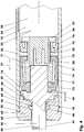
- Figur 4:
- Detail der
Figur 2 im Zylinderkopfbereich. - Die
Figuren 1 - 4 zeigen eine Verzögerungsvorrichtung (10), die z.B. in einem hier nicht weiter dargestellten Führungssystem eingesetzt ist. Dieses Führungssystem führt und trägt beispielsweise eine Schublade eines Möbelstücks. Es umfasst außer der Verzögerungsvorrichtung (10) z.B. eine Einzugsvorrichtung. Beispielsweise beim Einschieben der Schublade umgreift vor dem Erreichen der Endlage die an der Schublade angeordnete Verzögerungsvorrichtung (10) einen im Möbelstück fest angeordneten Mitnehmer. Die Hubbewegung der Schublade relativ zum Möbelstück wird verzögert. Gleichzeitig oder nach dem Zurücklegen eines weiteren Teilhubes in Richtung der Endlage wird mittels der Schublade die Einzugsvorrichtung ausgelöst. Die Einzugsvorrichtung zieht entgegen der Wirkung der Verzögerungsvorrichtung (10) die Schublade in die z.B. geschlossene Endlage. Die Verzögerungsvorrichtung (10) bleibt hierbei z.B. bis zum Erreichen der Endlage im Eingriff mit dem Mitnehmer. Auch der Einsatz einer pneumatischen Verzögerungsvorrichtung (10) ohne Einzugsvorrichtung ist denkbar. - Die Verzögerungsvorrichtung (10) umfasst einen Zylinder (21), in dem eine Kolbeneinheit (41), bestehend aus einem Kolben (51) und einer Kolbenstange (42), geführt ist. Der Kolben (51) trägt zwei Kolbendichtelemente (71, 72). Der Kolbenstangenkopf (43) der z.B. weitgehend zylindrischen Kolbenstange (42) ist in diesem Ausführungsbeispiel als Kugelkopf (43) ausgebildet. An diesen Kugelkopf (43) kann ein Mitnahmeelement, eine Anschlagplatte, etc. angeschlossen werden.
- Der Zylinder (21) umfasst einen topfförmigen Zylindermantel (22) mit einem integrierten Zylinderboden (28) und einem mittels einer Kolbenstangendichtung (62) verschlossenen Kopfteil (29). Er ist beispielsweise als Spritzgussteile aus thermoplastischem Kunststoff, z.B. Polyoximethylen, hergestellt. Der Zylindermantel (22) ist hier auf seiner Außenseite zylindrisch. Seine Länge beträgt beispielsweise das Fünfeinhalbfache des Durchmessers. Die nichtzylindrische Zylinderinnenwandung (23) ist z.B. in Form eines Kegelstumpfmantels ausgebildet. Die größere Querschnittsfläche dieses Kegelstumpfmantels befindet sich am Kopfteil (29) des Zylinders (21), die kleinere Querschnittsfläche am Zylinderboden (28). Die erstgenannte Querschnittsfläche beträgt z.B. 63 Quadratmillimeter. Die Steigung dieses Entformungskegels beträgt beispielsweise 1:65. Die Innenwandung (23) ist gegebenenfalls poliert. Die minimale Wandstärke des Zylindermantels (22) beträgt z.B. 7 % seines Außendurchmessers.
- Der Zylinderboden (28) hat einen in den Zylinderinnenraum (25) ragenden, kegelstumpfförmigen Stempel (31) mit einer Stempelstirnfläche (32). Dieser begrenzt zusammen mit der Innenwandung einen Ringraum (33). Die Querschnittsfläche des Ringraums (33) beträgt 80 % der größeren Querschnittsfläche des Kegelstumpfmantels. Seine Länge beträgt z.B. ein Siebtel des Kolbenhubs. Der Zylinder (21) kann auch ohne Stempel (31) ausgeführt sein.
- In der Zylinderinnenwandung (23) ist hier eine Längsnut (24) angeordnet, vgl.
Figur 4 . Ihre Länge beträgt beispielsweise 60 % der Zylinderlänge und endet je nach Ausführung des Zylinders (21) in der Ebene der Stempelstirnfläche (32) oder am Zylinderboden (28). Ihre Breite beträgt z.B. 2 % des größeren Durchmessers der Zylinderinnenwandung (23). Die Tiefe der Nut (24) beträgt in diesem Ausführungsbeispiel ein Viertel ihrer Breite. Die Nut (24) ist zur Innenwandung (23) hin scharfkantig, der Nutauslauf hat beispielsweise eine Steigung von 45 Grad. Statt einer einzelnen Nut (24) können auch mehrere Nuten (24) an der Innenwandung (23) angeordnet sein. Auch können sich diese z.B. schraubenlinienförmig an der Innenwandung (23) des Zylindermantels (22) entlangwinden. - Die Kolbenstangendichtung (62) hat einen außenliegenden Abstützring (63) und eine innenliegende Dichtlippe (64). Sie bildet die Kolbenstangendurchführung (61). Der Abstützring (63) liegt nichtabdichtend an der Kolbenstange (42) an. Die nach außen zeigende Dichtlippe (64) umgreift die Kolbenstange (42) und dichtet in der in der
Figur 1 dargestellten eingefahrenen Kolbenlage den Zylinderinnenraum (25) hermetisch gegen die Umgebung (1) ab. Ein nichtabdichtender Anschlagring (66) ist in Richtung des Zylinderinnenraums (25) orientiert. - Der Kolben (51) und die Kolbenstange (42) der Kolbeneinheit (41) sind beispielsweise formschlüssig und stoffschlüssig miteinander verbunden, sie können miteinander verklebt sein.
- Die Gesamtlänge der Kolbeneinheit (41) ist z.B. um 5 % länger als die Länge des Zylinders (21). Die Querschnittsfläche der beispielsweise aus Kunststoff hergestellten Kolbenstange (42) beträgt im Ausführungsbeispiel ein Achtel des Innenquerschnitts des Zylinders (21) am Zylinderkopf (29). Die Kolbenstange (42) kann biegbar sein.
- Die beiden Kolbendichtelemente (71, 72) sind zwischen einer Anschlagschulter (45) der Kolbeneinheit (41) und einer zum Verdrängungsraum (15) orientierten Bundscheibe (56) angeordnet. Das erste Kolbendichtelement (71) ist topfförmig ausgebildet. Es sitzt mit einem Einspannbereich (73) fest zwischen der Kolbenstange (42) und dem Kolben (51). An diesen Einspannbereich (73) schließt sich ein zumindest annähernd zylindermantelförmiger Manschettenbereich (74) an, der einen Verformungsbereich (74) bildet. Ein nach innen ragender Stützring (75) begrenzt dieses Kolbendichtelement (71) in der Längsrichtung (19). Dieser Stützring (75) ist in einer umlaufenden Kolbenausnehmung (52) geführt.
- Das zweite Dichtelement (72) sitzt in der Darstellung der
Figur 4 beabstandet zum ersten Dichtelement (71) in der Kolbenausnehmung (52). Dies ist ein in Richtung des Verdrängungsraums (15) geöffneter Wellendichtring (72) mit einem außenliegenden Dichtkragen (76). Die Kolbendichtelemente (71, 72) sind beispielsweise aus Nitril-Butadien-Kautschuk mit halogenisierter Oberfläche hergestellt. Die beiden Kolbendichtelemente (71, 72) können auch als ein gemeinsames Bauteil ausgebildet sein. Die Gesamtlänge der unbelasteten, voneinander beabstandeten Kolbendichtelemente (71, 72) ist im Folgenden als maximale Länge der Kolbendichtelemente (71, 72) bezeichnet. - Der Kolben (51) hat im Bereich der Kolbenausnehmung (52) zwei einander gegenüberliegende Längsnuten (53), die mit Aussparungen (57) der Bundscheibe (56) fluchten. Diese Längsnuten (53) verbinden den Druckraum (17) des ersten Kolbendichtelements (71) mit dem Verdrängungsraum (15).
- Die Kolbenstange (42) hat in dem an die Anschlagschulter (45) angrenzenden Abschnitt (46) in ihrer Mantelfläche (47) Längskanäle (48). Die Länge der z.B. gleichmäßig am Umfang verteilten Längskanäle (48) entspricht beispielsweise der Dicke der Zylinderkopfdichtung (62) in einer Richtung parallel zur Kolbenstange (42). Die Länge des mindestens einen Längskanals (48) entspricht beispielsweise der Länge der Dichtlippe (64) einschließlich ihres nichtanliegenden Bereichs (65). Der Längskanal (48) ragt jedoch in Richtung des Kolbenstangenkopfs (43) aus der Dichtlippe (64) heraus. Seine Tiefe beträgt beispielsweise 3 % des Durchmessers der Kolbenstange (42), seine Breite 16 % des Kolbenstangendurchmessers. Der Gesamtquerschnitt der Längskanäle (48) beträgt damit 5 % des Kolbenstangenquerschnitts.
- Anstatt der hier beschriebenen Längskanäle (48) kann die Kolbenstange (42) auch spiralförmig angeordnete Kanäle (48) aufweisen. Diese können gleich- oder gegenläufig sein, sie können sich schneiden oder durchdringen, etc.
- Im Ausführungsbeispiel ist in Längsrichtung (19) der Verzögerungsvorrichtung (10) der Abstand der Dichtlippe (64) der Zylinderkopfdichtung (62) zum Beginn der Nut (24) in der Zylinderinnenwandung (23) um drei Millimeter länger als der Abstand des Beginns der Längskanäle (48) zur verdrängungsraumseitigen Ende des Dichtkragens (76) des zweiten Kolbendichtelements (72). Die letztgenannte Länge ist die Summe aus der Länge der Längskanäle (48), der Länge eines Übergangsbereichs (44) zwischen den Längskanälen (48) und den Kolbendichtelementen (71, 72) sowie der maximalen Länge aller Kolbendichtelemente (71, 72).
- Nach der Montage begrenzen in diesem Ausführungsbeispiel der Kolben (51) und der Zylinderboden (28) den Verdrängungsraum (15). Der Kolben (51) und der Zylinderkopf (29) begrenzen einen Ausgleichsraum (16). Das Kolbendichtelement (71) und der Kolben (51) begrenzen nun einen Druckraum (17), der über die Längsnuten (53) und die Aussparungen (57) mit dem Verdrängungsraum (15) in Verbindung steht.
- Ist der Kolben (51) der Verzögerungsvorrichtung (10) ausgefahren, vgl.
Figuren 2 - 4 , befindet sich dieser im Bereich des größeren Innendurchmessers des Zylinders (21). Beispielsweise liegt er im nutfreien, glatten Bereich (26) der Zylinderinnenwandung (23). Der Dichtkragen (76) berührt nichtabdichtend die Zylinderinnenwandung (23). Der Manschettenbereich (74) liegt unverformt mit beidseitigem radialem Spiel zwischen der Zylinderinnenwandung (23) und dem Kolben (51). - Beim eingefahrenen Kolben (51), vgl.
Figur 1 , liegen die Kolbendichtelemente (71, 72) nichtabdichtend im Bereich der Längsnut (24) an der Zylinderinnenwandung (23) an. Die Längsnut (24) verbindet hierbei den Verdrängungs- (15) und den Ausgleichsraum (16). - Beispielsweise nach dem Einbau in ein Möbelstück ist z.B. bei ausgefahrener Schublade die Verzögerungsvorrichtung (10) außer Eingriff mit dem Mitnehmer. Die Kolbeneinheit (51) liegt in ihrer in den
Figuren 2 - 4 dargestellten ausgefahrenen Endlage. Hierbei kann die Anschlagschulter (45) an der Kolbenstangendichtung (62) anliegen. Die Verzögerungsvorrichtung (10) kann aber auch derart ausgebildet sein, dass in der ausgefahrenen Endlage der Kolbeneinheit (41) die Anschlagschulter (45) beispielsweise um 2 bis 3 Millimeter beabstandet von der Kolbenstangendichtung (62) ist. Hierfür kann z.B. ein mechanischer Anschlag an der Kolbenstange (42) außerhalb oder innerhalb des Zylinders (21) angeordnet sein. - Beispielsweise beim Schließen der Schublade umgreift in einem an die geschlossene Endlage der Schublade angrenzenden Teilhub des Gesamthubes der Mitnehmer den Kolbenstangenkopf (43) oder ein an diesem angeordnetes Mitnahmeelement.
- Die Kolbenstange (42) wird unter dem Einfluss der externen Kraft eingefahren. Der Kolben (51) wird hierbei vom Zylinderkopf (29), vgl.
Figur 2 - 4 , in Richtung des Zylinderbodens (28), vgl.Figur 1 , verschoben. Hierbei wird das Volumen des Verdrängungsraumes (15) - in der Darstellung derFiguren 2 und4 ist dieses Volumen maximal - vermindert. Der Gasdruck, z.B. der Luftdruck im Verdrängungsraum (15), erhöht sich und wirkt als interne Kraft auf das Kolbendichtelement (71). Nach dem Prinzip der Selbsthilfe wird unmittelbar mit dem Beginn der Einfahrbewegung der Kolbenstange (42) der Dichtkragen (76) unter Verformung an die Zylinderinnenwandung (23) angepresst. Der Verdrängungsraum (15) und der Ausgleichsraum (16) werden quasi hermetisch voneinander isoliert. Sobald die Dichtlippe (64) den zylindrischen Abschnitt (49) der Kolbenstange (42) erreicht hat, wird mittels der Kolbenstangendichtung (62) der Ausgleichsraum (16) hermetisch gegen die Umgebung (1) abgedichtet. Bei der weiteren Einfahrbewegung des Kolbens (51) wird im Ausgleichsraum (16) ein Unterdruck erzeugt. - Der Druck, der sich im Verdrängungsraum (15) aufbaut, wirkt auch auf die Innenfläche der Bremsmanschette (71). Der Manschettenbereich (74) wird radial nach außen gewölbt und an die Innenwandung (23) angepresst.
- Bei der Verformung der Bremsmanschette (71) wird das Kolbendichtelement (71) in axialer Richtung verkürzt. Der Stützring (75) wandert entlang der z.B. kegelstumpfförmigen Kolbenausnehmung (52) in Richtung der Kolbenstange (42) und drückt dabei den Verformungsbereich (74) zusätzlich radial nach außen, wobei die Bremswirkung der Bremsmanschette (71) verstärkt wird. Die Verbindungskanäle (53, 57) werden nicht unterbrochen, so dass der Verdrängungsraum (15) und der Druckraum (17) während des gesamten Hubes miteinander kommunizieren.
- Beim weiteren Einfahren der Kolbenstange (42) bewirken der an der Zylinderinnenwandung (23) angepresste Dichtkragen (76) und die an der Zylinderinnenwandung (23) anliegende Bremsmanschette (71) eine hohe Verzögerung der Kolbenhubbewegung. Die Schublade wird stark abgebremst.
- Mit zunehmendem Hub der Kolbenstange (42) erreicht der Dichtkragen (76) des Kolbendichtelements (72) den Beginn der Längsnut (24). Sobald der Dichtkragen (76) den hinteren Rand des Drosselkanals (24) passiert hat, wird Luft aus dem Verdrängungsraum (15) über den Drosselkanal (24) in den Ausgleichsraum (16) verdrängt. Der Druck im Verdrängungsraum (15) fällt z.B. schlagartig ab. Die Bremsmanschette (71) kann hierbei noch an der Zylinderinnenwandung (23) anliegen. Das aus dem Verdrängungsraum (15) verdrängte Volumen der Luft ist größer als das Volumen, um das der Ausgleichsraum (16) mit der ihn durchdringenden Kolbenstange (42) vergrößert wird. Der Druck im Ausgleichsraum (16) wird erhöht. Hierbei kann Luft aus dem Ausgleichsraum (16) durch die gegen die Umgebung (1) abdichtende Kolbenstangendichtung (62) hindurch in die Umgebung (1) entweichen.
- Sobald sich das Kolbendichtelement (71) vollständig von der Innenwandung (23) gelöst hat, strömt zusätzlich Luft aus dem Verdrängungsraum (15) in den Ausgleichsraum (16). Das Kolbendichtelement (71) nimmt wieder seine Ausgangslage vor dem Beginn der Hubbewegung an. Die Schublade hat jetzt eine geringe Restgeschwindigkeit. In der Endlage bleibt sie ohne Rückprall stehen.
- Während der Verzögerung der Hubbewegung kann die Schublade mit der Einzugsvorrichtung koppeln. Diese umfasst beispielsweise eine Feder, die eine zusätzliche interne Kraft auf die Führungsvorrichtung ausübt. Auf die Verzögerungsvorrichtung (10) wirkt diese Kraft als externe Kraft.
- Nach einem längeren Zeitintervall ohne weitere Betätigung der Verzögerungsvorrichtung (10) gleicht sich der Druck im Verdrängungsraum (15) und im Ausgleichsraum (16) dem Umgebungsdruck an. Es besteht keinerlei Gefahr, dass in der Ruhelage z.B. bei Materialermüdung die Verzögerungsvorrichtung (10) durch inneren Unter- oder Überdruck birst.
- Wird die Schublade wieder ausgezogen, strömt Luft aus dem Ausgleichsraum (16) über den Drosselkanal (24) in den Verdrängungsraum (15). Das Kolbendichtelement (71) bleibt weitgehend unverformt und hat zumindest während eines großen Teils des Hubes keinen Kontakt mit der Zylinderinnenwandung (23). Da während der Ausfahrbewegung die Luft weitgehend ungehindert aus dem Ausgleichsraum (16) in den Verdrängungsraum (15) strömt, verläuft die Auszugsbewegung zumindest annähernd widerstandsfrei.
- Während des Ausfahrens der Kolbeneinheit (41) wird der Ausgleichsraum (16) verkleinert und der Verdrängungsraum (15) vergrößert. Aufgrund des Volumens der Kolbenstange (42) ist das Volumen der verdrängten Luft kleiner als das Volumen, um das der Verdrängungsraum (15) vergrößert wird. Der Luftdruck im Verdrängungsraum (15) und im Ausgleichsraum (16) nimmt ab.
- Kurz vor dem Erreichen der ausgefahrenen Endlage der Kolbeneinheit (41) - der Verdängungsraum (15) hat sein maximales Volumen - erreicht die Dichtlippe (64) der Kolbenstangendichtung (62) die mindestens eine Längsnut (48) auf der Kolbenstange (42). Hiermit wird eine pneumatische Verbindung (18) zwischen dem Zylinderinnenraum (25) und der Umgebung (1) geöffnet. Aus der Umgebung (1) strömt Luft in den Ausgleichsraum (16) und in den Verdrängungsraum (15). Der Luftdruck in diesen Räumen (15, 16) gleicht sich an den Umgebungsdruck an.
- Sobald die Kolbenstange (42) vollständig ausgefahren ist, löst sich das kolbenstangenseitige Mitnahmlement vom möbelstückseitigen Mitnehmer. Die Verzögerungsvorrichtung (10) kommt außer Eingriff. Die Kolbenstange (42) der Verzögerungsvorrichtung (10) ist nun ausgefahren. Die Einzugsvorrichtung ist gelöst.
- Beim Wiedereinfahren des Kolbens (51) wird zunächst wieder die pneumatische Verbindung (18) des Zylinderinennraums (25) mit der Umgebung (1) verschlossen. Die Dichtlippe (64) gelangt auf den zylindrischen Bereich (49) der Kolbenstange (42). Erst beim weiteren Einfahren der Kolbeneinheit (41) gelangt der Dichtkragen (76) des Wellendichtrings (72) an die Längsnut (24) der Zylinderinnenwandung (23).
- Damit herrscht im Verdrängungsraum (15) bei Beginn jedes Verzögerungshubs der Umgebungsdruck. Die Verzögerungsvorrichtung (10) hat damit eine wiederholbare und konstante Leistung.
- Anstatt der Längskanäle (48) auf der Kolbenstange (42) kann die elastisch verformbare Kolbenstange (42) in der ausgefahrenen Endlage aus der gestreckten Lage gebogen werden. Hierbei wird die Kolbenstangendichtung (62) verformt und undicht, so dass zum Druckausgleich Luft aus der Umgebung (1) in den Ausgleichsraum (16) und in den Verdrängungsraum (15) strömen kann.
- Auch ist es denkbar, in der ausgefahrenen Endlage der Kolbeneinheit (41) ein separates Ventil zu öffnen. Dieses kann z.B. in der Kolbenstangendichtung (62) integriert sein.
- Die Verzögerungsvorrichtung (10) kann auch derart aufgebaut sein, dass der Verdrängungsraum (15) zwischen dem Kolben (51) und der Kolbenstangendichtung (62) angeordnet ist. Die Kolbenstange (42) durchdringt den Verdrängungsraum (15). Der Ausgleichsraum (16) befindet sich zwischen dem Kolben (51) und dem Zylinderboden (28).
- In einer derartigen Verzögerungsvorrichtung (10) erfolgt eine Verzögerung beim Herausziehen der Kolbenstange (42). Der nutfreie Bereich der Zylinderinennwandung (23) grenzt an den Zylinderboden an. In dieser Ausführungsform sind die Längskanäle (48) auf der Kolbenstange (42) z.B. in der Nähe des Kolbenstangenkopfes (43) angeordnet. Es ist auch in diesem Ausführungsbeispiel denkbar, die Kolbenstange (42) zu verformen oder in die Kolbenstangendichtung (62) ein Ventil anzuordnen, um in der Endlage der Kolbeneinheit (41) eine pneumatische Verbindung (18) zwischen dem Verdrängungsraum (15) und der Umgebung (1) herzustellen.
- Die hier beschriebene Verzögerungsvorrichtung (10) kann Teil eines Führungssystems sein.
-
- 1
- Umgebung
- 10
- Verzögerungsvorrichtung
- 15
- Verdrängungsraum
- 16
- Ausgleichsraum
- 17
- Druckraum
- 18
- pneumatische Verbindung
- 19
- Längsrichtung
- 21
- Zylinder
- 22
- Zylindermantel
- 23
- Zylinderinnenwandung
- 24
- Längsnut, Drosselkanal
- 25
- Zylinderinnenraum
- 26
- nutfreier Bereich von (23)
- 28
- zylinderboden
- 29
- Kopfteil, Zylinderkopf
- 31
- Stempel
- 32
- Stempelstirnfläche
- 33
- Ringraum
- 41
- Kolbeneinheit
- 42
- Kolbenstange
- 43
- Kolbenstangenkopf, Kugelkopf
- 44
- Übergangsbereich
- 45
- Anschlagschulter
- 46
- Abschnitt von (42)
- 47
- Mantelfläche
- 48
- Längskanäle
- 49
- zylindrischer Abschnitt von (42)
- 51
- Kolben
- 52
- Kolbenausnehmung
- 53
- Längsnuten
- 56
- Bundscheibe
- 57
- Aussparungen, Verbindungskanal
- 61
- Kolbenstangendurchführung
- 62
- Kolbenstangendichtung, Zylinderkopfdichtung
- 63
- Abstützring
- 64
- Dichtlippe
- 65
- nichtanliegender Bereich von (64)
- 66
- Anschlagring
- 71
- Kolbendichtelement, erstes Dichtelement, Bremsmanschette
- 72
- Kolbendichtelement, zweites Dichtelement, Wellendichtring
- 73
- Einspannbereich
- 74
- Manschettenbereich, Verformungsbereich
- 75
- Stützring
- 76
- Dichtlippe, Dichtkragen
Claims (6)
- Pneumatische Verzögerungsvorrichtung (10) mit einem Zylinder (21) und mit einem in diesem mittels einer von einer Kolbenstangendichtung (62) mit einer in Richtung eines Kolbenstangenkopfes (43) zeigenden Dichtlippe (64) umgriffenen Kolbenstange (42) geführten, mit mindestens einem Kolbendichtelement (71; 72) ausgestatteten, einen Verdrängungsraum (15) gegen einen Ausgleichsraum (16) abgrenzenden Kolben (51), die durch Überdruck im Verdrängungsraum (15) und Unterdruck im Ausgleichsraum (16) eine der Hubbewegung des Kolbens (51) entgegengesetzte Kraft aufbaut, wobei der Leckagestrom zwischen dem Verdrängungsraum (15) und dem Ausgleichsraum (16) zumindest hubrichtungsabhängig ist und wobei das Kolbendichtelement (71; 72) beim Druckaufbau im Verdrängungsraum (15) den Verdrängungsraum (15) und den Ausgleichsraum (16) quasi hermetisch voneinander isoliert, dadurch gekennzeichnet,- dass die Verzögerungsvorrichtung (10) in der Kolbenendlage des maximalen Verdrängungsraums (15) eine verschließbare pneumatische Verbindung (18) aufweist, so dass in dieser Endlage der Verdrängungsraum (15) und der Ausgleichsraum (16) mittels dieser Verbindung (18) mit der Umgebung (1) kommunizieren und- dass die Kolbenstangendichtung (62) bei geschlossener Verbindung (18) den Zylinderinnenraum (25) zur Erzeugung des Unterdrucks im Ausgleichsraum (16) hermetisch gegen die Umgebung (1) abdichtet.
- Verzögerungsvorrichtung (10) nach Anspruch 1, dadurch gekennzeichnet, dass die pneumatische Verbindung (18) in der Kolbenstangendichtung (62) und/oder in der Kolbenstange (42) angeordnet ist.
- Pneumatische Verzögerungsvorrichtung (10) nach Anspruch 1, dadurch gekennzeichnet, dass die pneumatische Verbindung (18) durch mindestens einen auf der Kolbenstange (42) angeordneten Längskanal (48) gebildet wird.
- Pneumatische Verzögerungsvorrichtung (10) nach Anspruch 3, dadurch gekennzeichnet, dass die Länge des Längskanals (48) kürzer ist als 5 % des Kolbenhubs.
- Pneumatische Verzögerungsvorrichtung (10) nach Anspruch 1, dadurch gekennzeichnet, dass der Zylinder (21) eine Zylinderinnenwandung (23) mit mindestens einer in Längsrichtung (19) orientierten Längsnut (24) hat, wobei die Länge der Längsnut (24) maximal 90 % der Länge des Zylinders (21) beträgt und wobei der Kolben (51) in der Endlage des maximalen Verdrängungsraums (15) in einem nutfreien Bereich (26) der Zylinderinnenwandung (23) liegt.
- Pneumatische Verzögerungsvorrichtung (10) nach den Ansprüchen 2, 4 und 5, dadurch gekennzeichnet, dass die Summe der Länge des Längskanals (48), der maximalen Länge aller Kolbendichtelemente (71, 72) sowie der Länge eines Übergangsbereichs (44) kürzer ist als der in Längsrichtung (19) gemessene Abstand der Einlippendichtung (64) zum vedrängungsraumseitigen Ende des nutfreien Bereichs (26) der Zylinderinnenwandung (23).
Priority Applications (1)
| Application Number | Priority Date | Filing Date | Title |
|---|---|---|---|
| PL11809297T PL2585735T3 (pl) | 2010-06-24 | 2011-06-22 | Pneumatyczne urządzenie spowalniające o stałej sile działania |
Applications Claiming Priority (2)
| Application Number | Priority Date | Filing Date | Title |
|---|---|---|---|
| DE201010024994 DE102010024994B4 (de) | 2010-06-24 | 2010-06-24 | Pneumatische Verzögerungsvorrichtung mit konstanter Leistung |
| PCT/DE2011/001356 WO2012010136A2 (de) | 2010-06-24 | 2011-06-22 | Pneumatische verzögerungsvorrichtung mit konstanter leistung |
Publications (2)
| Publication Number | Publication Date |
|---|---|
| EP2585735A2 EP2585735A2 (de) | 2013-05-01 |
| EP2585735B1 true EP2585735B1 (de) | 2019-08-14 |
Family
ID=45115542
Family Applications (1)
| Application Number | Title | Priority Date | Filing Date |
|---|---|---|---|
| EP11809297.2A Active EP2585735B1 (de) | 2010-06-24 | 2011-06-22 | Pneumatische verzögerungsvorrichtung mit konstanter leistung |
Country Status (6)
| Country | Link |
|---|---|
| US (1) | US9127493B2 (de) |
| EP (1) | EP2585735B1 (de) |
| JP (1) | JP5826258B2 (de) |
| DE (1) | DE102010024994B4 (de) |
| PL (1) | PL2585735T3 (de) |
| WO (1) | WO2012010136A2 (de) |
Families Citing this family (11)
| Publication number | Priority date | Publication date | Assignee | Title |
|---|---|---|---|---|
| GB2498747B (en) * | 2012-01-24 | 2018-05-09 | Titus Int Ltd | Improvements in damper assemblies |
| CN107636366B (zh) * | 2015-06-15 | 2021-03-12 | 卡明斯公司 | 燃烧室弹性装置 |
| KR101783546B1 (ko) * | 2016-04-08 | 2017-09-29 | 홍정기 | 창호용 에어 댐퍼 |
| JP6992165B2 (ja) * | 2018-03-28 | 2022-01-17 | 株式会社パイオラックス | ダンパー |
| JP7354239B2 (ja) | 2018-07-06 | 2023-10-02 | モシュン,エルエルシー | 調整可能な扉閉鎖制御のためのシステムおよびデバイス |
| JP7444766B2 (ja) | 2020-12-18 | 2024-03-06 | 株式会社パイオラックス | ダンパー |
| US11841065B2 (en) | 2021-01-08 | 2023-12-12 | Moshun, LLC | Systems and devices for motion control |
| JP7449885B2 (ja) * | 2021-02-15 | 2024-03-14 | 株式会社ニフコ | ダンパー装置 |
| GB2643979A (en) * | 2022-03-10 | 2026-03-11 | Piolax Inc | Damper device |
| US12467302B2 (en) * | 2022-03-23 | 2025-11-11 | Moshun, LLC | Systems and devices for motion control |
| US11959529B1 (en) * | 2023-08-14 | 2024-04-16 | Alfred Franklin Nibecker | Allow air springs to be self-charging |
Citations (2)
| Publication number | Priority date | Publication date | Assignee | Title |
|---|---|---|---|---|
| US5697477A (en) * | 1994-10-07 | 1997-12-16 | Nifco Inc. | Air damper |
| US20040032068A1 (en) * | 2002-08-19 | 2004-02-19 | Nifco Inc. | Damper |
Family Cites Families (15)
| Publication number | Priority date | Publication date | Assignee | Title |
|---|---|---|---|---|
| FR1588502A (de) | 1968-06-28 | 1970-04-17 | ||
| DE2415204A1 (de) | 1973-04-03 | 1974-10-24 | Klein Ets Georges | Sperrvorrichtung, insbesondere fuer die beweglichen elemente von fensteroeffnungen, im besonderen fuer fahrzeuge, wie wohnwagenanhaenger oder dergleichen |
| DE2516478C3 (de) * | 1975-04-15 | 1978-12-07 | Suspa-Federungstechnik Fritz Bauer & Soehne Ohg, 8503 Altdorf | Gasfeder |
| JPS583160B2 (ja) * | 1976-03-19 | 1983-01-20 | トキコ株式会社 | 圧力容器へのガス封入方法 |
| JPS6035812Y2 (ja) * | 1979-11-09 | 1985-10-24 | トキコ株式会社 | ガススプリング |
| DE3301544A1 (de) * | 1983-01-19 | 1984-07-19 | Stabilus Gmbh, 5400 Koblenz | Gasfeder als huborgan zum oeffnen von nach oben schwenkbaren klappen |
| US4683992A (en) * | 1985-09-13 | 1987-08-04 | Ford Motor Company | Vehicle suspension damper with remote control |
| IT1210723B (it) * | 1987-05-11 | 1989-09-20 | Boge Italia Spa | Molla a gas a spinta variabile |
| DE3817776A1 (de) * | 1988-05-26 | 1989-12-07 | Bauer Fritz & Soehne Ohg | Gasfeder |
| DE4003245C2 (de) * | 1990-02-03 | 1997-08-21 | Stabilus Gmbh | Führung für teleskopartig ineinander verschiebbare zylindrische Teile |
| JPH08105482A (ja) * | 1994-10-07 | 1996-04-23 | Nifco Inc | エアダンパ |
| DE4442547C1 (de) | 1994-11-30 | 1996-06-05 | Daimler Benz Ag | Feststellvorrichtung für eine aufschwenkbare Fahrzeugklappe |
| DE20122569U1 (de) * | 2001-01-09 | 2006-04-27 | Julius Blum Gmbh | Brems- und Dämpfeinrichtung, insbesondere für bewegbare Möbel |
| DE10313659B3 (de) * | 2003-03-26 | 2004-09-30 | Zimmer, Günther Stephan | Pneumatische Verzögerungsvorrichtung zum Abbremsen beweglicher Möbelteile |
| DE102006040085A1 (de) * | 2006-08-28 | 2008-03-20 | Zimmer, Günther | Kostengünstig herstellbare pneumatische Verzögerungsvorrichtung |
-
2010
- 2010-06-24 DE DE201010024994 patent/DE102010024994B4/de not_active Expired - Fee Related
-
2011
- 2011-06-22 PL PL11809297T patent/PL2585735T3/pl unknown
- 2011-06-22 WO PCT/DE2011/001356 patent/WO2012010136A2/de not_active Ceased
- 2011-06-22 JP JP2013515692A patent/JP5826258B2/ja not_active Expired - Fee Related
- 2011-06-22 EP EP11809297.2A patent/EP2585735B1/de active Active
-
2012
- 2012-12-16 US US13/716,157 patent/US9127493B2/en active Active
Patent Citations (2)
| Publication number | Priority date | Publication date | Assignee | Title |
|---|---|---|---|---|
| US5697477A (en) * | 1994-10-07 | 1997-12-16 | Nifco Inc. | Air damper |
| US20040032068A1 (en) * | 2002-08-19 | 2004-02-19 | Nifco Inc. | Damper |
Also Published As
| Publication number | Publication date |
|---|---|
| JP5826258B2 (ja) | 2015-12-02 |
| JP2013531154A (ja) | 2013-08-01 |
| US20130118846A1 (en) | 2013-05-16 |
| WO2012010136A3 (de) | 2012-06-14 |
| DE102010024994B4 (de) | 2012-06-14 |
| WO2012010136A2 (de) | 2012-01-26 |
| PL2585735T3 (pl) | 2020-02-28 |
| DE102010024994A1 (de) | 2011-12-29 |
| US9127493B2 (en) | 2015-09-08 |
| EP2585735A2 (de) | 2013-05-01 |
Similar Documents
| Publication | Publication Date | Title |
|---|---|---|
| EP2585735B1 (de) | Pneumatische verzögerungsvorrichtung mit konstanter leistung | |
| DE10214596B4 (de) | Führungssystem mit pneumatischer Verzögerungsvorrichtung | |
| EP1606532B1 (de) | Pneumatische verzögerungsvorrinchtung zum abbremsen beweglicher möbelteile | |
| EP2951458B1 (de) | Zylinder-kolben-einheit mit kolbendrossel | |
| DE20204986U1 (de) | Dämpfungsvorrichtung für bewegliche Möbelteile | |
| EP2057387B1 (de) | Kostengünstig herstellbare pneumatische verzögerungsvorrichtung | |
| DE112014002401T5 (de) | Verriegelungsmechanismus für Motorhauben-Anhebeeinrichtungen für Fußgänger | |
| EP3452344A1 (de) | Hydraulikzylinder, insbesondere hauptbremszylinder für hydraulische bremsanlagen | |
| DE3825077A1 (de) | Laengeneinstellbare verstelleinrichtung | |
| DE102007060472A1 (de) | Zweiteiliger Kolben für einen Verbrennungsmotor | |
| EP3458739A1 (de) | Schwingungsdämpfer mit hubabhängiger dämpfkraft | |
| EP2962022B1 (de) | Überströmventil | |
| EP2855943B1 (de) | Geberzylinder | |
| DE112008002530B4 (de) | Nehmerzylinder und Ausrücksystem | |
| EP1585909B1 (de) | Führungssystem mit pneumatischer verzögerungsvorrichtung | |
| DE102008010908B4 (de) | Kolbendichtelement und Verzögerungsvorrichtung mit Kolbendichtelement | |
| EP1662168B1 (de) | Pneumatische Verzögerungseinrichtung zum Abbremsen beweglicher Möbelteile, insbesondere von Auszügen | |
| DE2404111B2 (de) | Hydraulischer Einrohr-Stoßdämpfer | |
| DE102017106106A1 (de) | Dichtung für Kolben-Zylinder-Anordnung | |
| DE102012214713B4 (de) | Hydraulische Kolben-/Zylindereinheit | |
| DE102015217789A1 (de) | Druckzylinder, insbesondere Geberzylinder, mit bewegter Dichtung sowie bewegter Hülse und variabler Ausrückkraft | |
| DE102016201386B4 (de) | Gasdruckfeder | |
| DE2359751B2 (de) | ||
| DE202022000256U1 (de) | Pneumatische Verzögerungsvorrichtung mit wiederverwertbaren Werkstoffen | |
| EP4172520A1 (de) | Ventil und verfahren zur steuerung eines strömungsmittels mit dem ventil |
Legal Events
| Date | Code | Title | Description |
|---|---|---|---|
| PUAI | Public reference made under article 153(3) epc to a published international application that has entered the european phase |
Free format text: ORIGINAL CODE: 0009012 |
|
| 17P | Request for examination filed |
Effective date: 20130117 |
|
| AK | Designated contracting states |
Kind code of ref document: A2 Designated state(s): AL AT BE BG CH CY CZ DE DK EE ES FI FR GB GR HR HU IE IS IT LI LT LU LV MC MK MT NL NO PL PT RO RS SE SI SK SM TR |
|
| DAX | Request for extension of the european patent (deleted) | ||
| 17Q | First examination report despatched |
Effective date: 20140718 |
|
| GRAP | Despatch of communication of intention to grant a patent |
Free format text: ORIGINAL CODE: EPIDOSNIGR1 |
|
| STAA | Information on the status of an ep patent application or granted ep patent |
Free format text: STATUS: GRANT OF PATENT IS INTENDED |
|
| INTG | Intention to grant announced |
Effective date: 20190320 |
|
| GRAS | Grant fee paid |
Free format text: ORIGINAL CODE: EPIDOSNIGR3 |
|
| GRAA | (expected) grant |
Free format text: ORIGINAL CODE: 0009210 |
|
| STAA | Information on the status of an ep patent application or granted ep patent |
Free format text: STATUS: THE PATENT HAS BEEN GRANTED |
|
| AK | Designated contracting states |
Kind code of ref document: B1 Designated state(s): AL AT BE BG CH CY CZ DE DK EE ES FI FR GB GR HR HU IE IS IT LI LT LU LV MC MK MT NL NO PL PT RO RS SE SI SK SM TR |
|
| REG | Reference to a national code |
Ref country code: GB Ref legal event code: FG4D Free format text: NOT ENGLISH |
|
| REG | Reference to a national code |
Ref country code: CH Ref legal event code: EP Ref country code: AT Ref legal event code: REF Ref document number: 1167395 Country of ref document: AT Kind code of ref document: T Effective date: 20190815 |
|
| REG | Reference to a national code |
Ref country code: IE Ref legal event code: FG4D Free format text: LANGUAGE OF EP DOCUMENT: GERMAN |
|
| REG | Reference to a national code |
Ref country code: DE Ref legal event code: R096 Ref document number: 502011016008 Country of ref document: DE |
|
| REG | Reference to a national code |
Ref country code: NL Ref legal event code: FP |
|
| REG | Reference to a national code |
Ref country code: LT Ref legal event code: MG4D |
|
| PG25 | Lapsed in a contracting state [announced via postgrant information from national office to epo] |
Ref country code: FI Free format text: LAPSE BECAUSE OF FAILURE TO SUBMIT A TRANSLATION OF THE DESCRIPTION OR TO PAY THE FEE WITHIN THE PRESCRIBED TIME-LIMIT Effective date: 20190814 Ref country code: NO Free format text: LAPSE BECAUSE OF FAILURE TO SUBMIT A TRANSLATION OF THE DESCRIPTION OR TO PAY THE FEE WITHIN THE PRESCRIBED TIME-LIMIT Effective date: 20191114 Ref country code: BG Free format text: LAPSE BECAUSE OF FAILURE TO SUBMIT A TRANSLATION OF THE DESCRIPTION OR TO PAY THE FEE WITHIN THE PRESCRIBED TIME-LIMIT Effective date: 20191114 Ref country code: SE Free format text: LAPSE BECAUSE OF FAILURE TO SUBMIT A TRANSLATION OF THE DESCRIPTION OR TO PAY THE FEE WITHIN THE PRESCRIBED TIME-LIMIT Effective date: 20190814 Ref country code: HR Free format text: LAPSE BECAUSE OF FAILURE TO SUBMIT A TRANSLATION OF THE DESCRIPTION OR TO PAY THE FEE WITHIN THE PRESCRIBED TIME-LIMIT Effective date: 20190814 Ref country code: LT Free format text: LAPSE BECAUSE OF FAILURE TO SUBMIT A TRANSLATION OF THE DESCRIPTION OR TO PAY THE FEE WITHIN THE PRESCRIBED TIME-LIMIT Effective date: 20190814 Ref country code: PT Free format text: LAPSE BECAUSE OF FAILURE TO SUBMIT A TRANSLATION OF THE DESCRIPTION OR TO PAY THE FEE WITHIN THE PRESCRIBED TIME-LIMIT Effective date: 20191216 |
|
| PG25 | Lapsed in a contracting state [announced via postgrant information from national office to epo] |
Ref country code: RS Free format text: LAPSE BECAUSE OF FAILURE TO SUBMIT A TRANSLATION OF THE DESCRIPTION OR TO PAY THE FEE WITHIN THE PRESCRIBED TIME-LIMIT Effective date: 20190814 Ref country code: IS Free format text: LAPSE BECAUSE OF FAILURE TO SUBMIT A TRANSLATION OF THE DESCRIPTION OR TO PAY THE FEE WITHIN THE PRESCRIBED TIME-LIMIT Effective date: 20191214 Ref country code: LV Free format text: LAPSE BECAUSE OF FAILURE TO SUBMIT A TRANSLATION OF THE DESCRIPTION OR TO PAY THE FEE WITHIN THE PRESCRIBED TIME-LIMIT Effective date: 20190814 Ref country code: GR Free format text: LAPSE BECAUSE OF FAILURE TO SUBMIT A TRANSLATION OF THE DESCRIPTION OR TO PAY THE FEE WITHIN THE PRESCRIBED TIME-LIMIT Effective date: 20191115 Ref country code: AL Free format text: LAPSE BECAUSE OF FAILURE TO SUBMIT A TRANSLATION OF THE DESCRIPTION OR TO PAY THE FEE WITHIN THE PRESCRIBED TIME-LIMIT Effective date: 20190814 Ref country code: ES Free format text: LAPSE BECAUSE OF FAILURE TO SUBMIT A TRANSLATION OF THE DESCRIPTION OR TO PAY THE FEE WITHIN THE PRESCRIBED TIME-LIMIT Effective date: 20190814 |
|
| PG25 | Lapsed in a contracting state [announced via postgrant information from national office to epo] |
Ref country code: TR Free format text: LAPSE BECAUSE OF FAILURE TO SUBMIT A TRANSLATION OF THE DESCRIPTION OR TO PAY THE FEE WITHIN THE PRESCRIBED TIME-LIMIT Effective date: 20190814 |
|
| PG25 | Lapsed in a contracting state [announced via postgrant information from national office to epo] |
Ref country code: EE Free format text: LAPSE BECAUSE OF FAILURE TO SUBMIT A TRANSLATION OF THE DESCRIPTION OR TO PAY THE FEE WITHIN THE PRESCRIBED TIME-LIMIT Effective date: 20190814 Ref country code: DK Free format text: LAPSE BECAUSE OF FAILURE TO SUBMIT A TRANSLATION OF THE DESCRIPTION OR TO PAY THE FEE WITHIN THE PRESCRIBED TIME-LIMIT Effective date: 20190814 Ref country code: RO Free format text: LAPSE BECAUSE OF FAILURE TO SUBMIT A TRANSLATION OF THE DESCRIPTION OR TO PAY THE FEE WITHIN THE PRESCRIBED TIME-LIMIT Effective date: 20190814 |
|
| PG25 | Lapsed in a contracting state [announced via postgrant information from national office to epo] |
Ref country code: SK Free format text: LAPSE BECAUSE OF FAILURE TO SUBMIT A TRANSLATION OF THE DESCRIPTION OR TO PAY THE FEE WITHIN THE PRESCRIBED TIME-LIMIT Effective date: 20190814 Ref country code: SM Free format text: LAPSE BECAUSE OF FAILURE TO SUBMIT A TRANSLATION OF THE DESCRIPTION OR TO PAY THE FEE WITHIN THE PRESCRIBED TIME-LIMIT Effective date: 20190814 Ref country code: CZ Free format text: LAPSE BECAUSE OF FAILURE TO SUBMIT A TRANSLATION OF THE DESCRIPTION OR TO PAY THE FEE WITHIN THE PRESCRIBED TIME-LIMIT Effective date: 20190814 Ref country code: IS Free format text: LAPSE BECAUSE OF FAILURE TO SUBMIT A TRANSLATION OF THE DESCRIPTION OR TO PAY THE FEE WITHIN THE PRESCRIBED TIME-LIMIT Effective date: 20200224 |
|
| REG | Reference to a national code |
Ref country code: DE Ref legal event code: R097 Ref document number: 502011016008 Country of ref document: DE |
|
| PLBE | No opposition filed within time limit |
Free format text: ORIGINAL CODE: 0009261 |
|
| STAA | Information on the status of an ep patent application or granted ep patent |
Free format text: STATUS: NO OPPOSITION FILED WITHIN TIME LIMIT |
|
| PG2D | Information on lapse in contracting state deleted |
Ref country code: IS |
|
| 26N | No opposition filed |
Effective date: 20200603 |
|
| PG25 | Lapsed in a contracting state [announced via postgrant information from national office to epo] |
Ref country code: SI Free format text: LAPSE BECAUSE OF FAILURE TO SUBMIT A TRANSLATION OF THE DESCRIPTION OR TO PAY THE FEE WITHIN THE PRESCRIBED TIME-LIMIT Effective date: 20190814 |
|
| PGFP | Annual fee paid to national office [announced via postgrant information from national office to epo] |
Ref country code: NL Payment date: 20200707 Year of fee payment: 10 |
|
| PG25 | Lapsed in a contracting state [announced via postgrant information from national office to epo] |
Ref country code: MC Free format text: LAPSE BECAUSE OF FAILURE TO SUBMIT A TRANSLATION OF THE DESCRIPTION OR TO PAY THE FEE WITHIN THE PRESCRIBED TIME-LIMIT Effective date: 20190814 |
|
| REG | Reference to a national code |
Ref country code: CH Ref legal event code: PL |
|
| PG25 | Lapsed in a contracting state [announced via postgrant information from national office to epo] |
Ref country code: LU Free format text: LAPSE BECAUSE OF NON-PAYMENT OF DUE FEES Effective date: 20200622 |
|
| REG | Reference to a national code |
Ref country code: BE Ref legal event code: MM Effective date: 20200630 |
|
| PG25 | Lapsed in a contracting state [announced via postgrant information from national office to epo] |
Ref country code: CH Free format text: LAPSE BECAUSE OF NON-PAYMENT OF DUE FEES Effective date: 20200630 Ref country code: IE Free format text: LAPSE BECAUSE OF NON-PAYMENT OF DUE FEES Effective date: 20200622 Ref country code: LI Free format text: LAPSE BECAUSE OF NON-PAYMENT OF DUE FEES Effective date: 20200630 |
|
| PG25 | Lapsed in a contracting state [announced via postgrant information from national office to epo] |
Ref country code: BE Free format text: LAPSE BECAUSE OF NON-PAYMENT OF DUE FEES Effective date: 20200630 |
|
| REG | Reference to a national code |
Ref country code: AT Ref legal event code: MM01 Ref document number: 1167395 Country of ref document: AT Kind code of ref document: T Effective date: 20200622 |
|
| PG25 | Lapsed in a contracting state [announced via postgrant information from national office to epo] |
Ref country code: AT Free format text: LAPSE BECAUSE OF NON-PAYMENT OF DUE FEES Effective date: 20200622 |
|
| REG | Reference to a national code |
Ref country code: NL Ref legal event code: MM Effective date: 20210701 |
|
| PG25 | Lapsed in a contracting state [announced via postgrant information from national office to epo] |
Ref country code: NL Free format text: LAPSE BECAUSE OF NON-PAYMENT OF DUE FEES Effective date: 20210701 Ref country code: MT Free format text: LAPSE BECAUSE OF FAILURE TO SUBMIT A TRANSLATION OF THE DESCRIPTION OR TO PAY THE FEE WITHIN THE PRESCRIBED TIME-LIMIT Effective date: 20190814 Ref country code: CY Free format text: LAPSE BECAUSE OF FAILURE TO SUBMIT A TRANSLATION OF THE DESCRIPTION OR TO PAY THE FEE WITHIN THE PRESCRIBED TIME-LIMIT Effective date: 20190814 |
|
| PG25 | Lapsed in a contracting state [announced via postgrant information from national office to epo] |
Ref country code: MK Free format text: LAPSE BECAUSE OF FAILURE TO SUBMIT A TRANSLATION OF THE DESCRIPTION OR TO PAY THE FEE WITHIN THE PRESCRIBED TIME-LIMIT Effective date: 20190814 |
|
| PGFP | Annual fee paid to national office [announced via postgrant information from national office to epo] |
Ref country code: DE Payment date: 20250630 Year of fee payment: 15 Ref country code: PL Payment date: 20250430 Year of fee payment: 15 |
|
| PGFP | Annual fee paid to national office [announced via postgrant information from national office to epo] |
Ref country code: GB Payment date: 20250621 Year of fee payment: 15 |
|
| PGFP | Annual fee paid to national office [announced via postgrant information from national office to epo] |
Ref country code: FR Payment date: 20250617 Year of fee payment: 15 |
|
| PGFP | Annual fee paid to national office [announced via postgrant information from national office to epo] |
Ref country code: IT Payment date: 20250627 Year of fee payment: 15 |