EP2585735B1 - Dispositif ralentisseur pneumatique à puissance constante - Google Patents
Dispositif ralentisseur pneumatique à puissance constante Download PDFInfo
- Publication number
- EP2585735B1 EP2585735B1 EP11809297.2A EP11809297A EP2585735B1 EP 2585735 B1 EP2585735 B1 EP 2585735B1 EP 11809297 A EP11809297 A EP 11809297A EP 2585735 B1 EP2585735 B1 EP 2585735B1
- Authority
- EP
- European Patent Office
- Prior art keywords
- piston
- piston rod
- cylinder
- space
- deceleration device
- Prior art date
- Legal status (The legal status is an assumption and is not a legal conclusion. Google has not performed a legal analysis and makes no representation as to the accuracy of the status listed.)
- Active
Links
- 238000007789 sealing Methods 0.000 claims description 57
- 238000006073 displacement reaction Methods 0.000 claims description 46
- 230000001419 dependent effect Effects 0.000 claims description 3
- 230000007704 transition Effects 0.000 claims description 3
- 230000000979 retarding effect Effects 0.000 description 5
- 241000237942 Conidae Species 0.000 description 2
- 229920000459 Nitrile rubber Polymers 0.000 description 1
- 229930040373 Paraformaldehyde Natural products 0.000 description 1
- -1 Polyoxymethylene Polymers 0.000 description 1
- 230000002146 bilateral effect Effects 0.000 description 1
- 230000007423 decrease Effects 0.000 description 1
- 230000003111 delayed effect Effects 0.000 description 1
- 230000003292 diminished effect Effects 0.000 description 1
- 230000000694 effects Effects 0.000 description 1
- 238000002347 injection Methods 0.000 description 1
- 239000007924 injection Substances 0.000 description 1
- 238000009434 installation Methods 0.000 description 1
- 239000000463 material Substances 0.000 description 1
- 230000000149 penetrating effect Effects 0.000 description 1
- 239000004033 plastic Substances 0.000 description 1
- 229920006324 polyoxymethylene Polymers 0.000 description 1
- 230000000284 resting effect Effects 0.000 description 1
- 229920001169 thermoplastic Polymers 0.000 description 1
- 239000004416 thermosoftening plastic Substances 0.000 description 1
- 230000001960 triggered effect Effects 0.000 description 1
Images
Classifications
-
- F—MECHANICAL ENGINEERING; LIGHTING; HEATING; WEAPONS; BLASTING
- F16—ENGINEERING ELEMENTS AND UNITS; GENERAL MEASURES FOR PRODUCING AND MAINTAINING EFFECTIVE FUNCTIONING OF MACHINES OR INSTALLATIONS; THERMAL INSULATION IN GENERAL
- F16F—SPRINGS; SHOCK-ABSORBERS; MEANS FOR DAMPING VIBRATION
- F16F9/00—Springs, vibration-dampers, shock-absorbers, or similarly-constructed movement-dampers using a fluid or the equivalent as damping medium
- F16F9/32—Details
- F16F9/36—Special sealings, including sealings or guides for piston-rods
- F16F9/368—Sealings in pistons
-
- E—FIXED CONSTRUCTIONS
- E05—LOCKS; KEYS; WINDOW OR DOOR FITTINGS; SAFES
- E05F—DEVICES FOR MOVING WINGS INTO OPEN OR CLOSED POSITION; CHECKS FOR WINGS; WING FITTINGS NOT OTHERWISE PROVIDED FOR, CONCERNED WITH THE FUNCTIONING OF THE WING
- E05F3/00—Closers or openers with braking devices, e.g. checks; Construction of pneumatic or liquid braking devices
- E05F3/02—Closers or openers with braking devices, e.g. checks; Construction of pneumatic or liquid braking devices with pneumatic piston brakes
-
- F—MECHANICAL ENGINEERING; LIGHTING; HEATING; WEAPONS; BLASTING
- F16—ENGINEERING ELEMENTS AND UNITS; GENERAL MEASURES FOR PRODUCING AND MAINTAINING EFFECTIVE FUNCTIONING OF MACHINES OR INSTALLATIONS; THERMAL INSULATION IN GENERAL
- F16F—SPRINGS; SHOCK-ABSORBERS; MEANS FOR DAMPING VIBRATION
- F16F9/00—Springs, vibration-dampers, shock-absorbers, or similarly-constructed movement-dampers using a fluid or the equivalent as damping medium
- F16F9/02—Springs, vibration-dampers, shock-absorbers, or similarly-constructed movement-dampers using a fluid or the equivalent as damping medium using gas only or vacuum
- F16F9/0209—Telescopic
- F16F9/0218—Mono-tubular units
-
- F—MECHANICAL ENGINEERING; LIGHTING; HEATING; WEAPONS; BLASTING
- F16—ENGINEERING ELEMENTS AND UNITS; GENERAL MEASURES FOR PRODUCING AND MAINTAINING EFFECTIVE FUNCTIONING OF MACHINES OR INSTALLATIONS; THERMAL INSULATION IN GENERAL
- F16F—SPRINGS; SHOCK-ABSORBERS; MEANS FOR DAMPING VIBRATION
- F16F9/00—Springs, vibration-dampers, shock-absorbers, or similarly-constructed movement-dampers using a fluid or the equivalent as damping medium
- F16F9/32—Details
- F16F9/3207—Constructional features
- F16F9/3221—Constructional features of piston rods
-
- F—MECHANICAL ENGINEERING; LIGHTING; HEATING; WEAPONS; BLASTING
- F16—ENGINEERING ELEMENTS AND UNITS; GENERAL MEASURES FOR PRODUCING AND MAINTAINING EFFECTIVE FUNCTIONING OF MACHINES OR INSTALLATIONS; THERMAL INSULATION IN GENERAL
- F16F—SPRINGS; SHOCK-ABSORBERS; MEANS FOR DAMPING VIBRATION
- F16F9/00—Springs, vibration-dampers, shock-absorbers, or similarly-constructed movement-dampers using a fluid or the equivalent as damping medium
- F16F9/32—Details
- F16F9/43—Filling or drainage arrangements, e.g. for supply of gas
- F16F9/432—Filling or drainage arrangements, e.g. for supply of gas via piston rod sealing or guiding means
-
- F—MECHANICAL ENGINEERING; LIGHTING; HEATING; WEAPONS; BLASTING
- F16—ENGINEERING ELEMENTS AND UNITS; GENERAL MEASURES FOR PRODUCING AND MAINTAINING EFFECTIVE FUNCTIONING OF MACHINES OR INSTALLATIONS; THERMAL INSULATION IN GENERAL
- F16F—SPRINGS; SHOCK-ABSORBERS; MEANS FOR DAMPING VIBRATION
- F16F9/00—Springs, vibration-dampers, shock-absorbers, or similarly-constructed movement-dampers using a fluid or the equivalent as damping medium
- F16F9/32—Details
- F16F9/50—Special means providing automatic damping adjustment, i.e. self-adjustment of damping by particular sliding movements of a valve element, other than flexions or displacement of valve discs; Special means providing self-adjustment of spring characteristics
- F16F9/516—Special means providing automatic damping adjustment, i.e. self-adjustment of damping by particular sliding movements of a valve element, other than flexions or displacement of valve discs; Special means providing self-adjustment of spring characteristics resulting in the damping effects during contraction being different from the damping effects during extension, i.e. responsive to the direction of movement
Definitions
- the invention relates to a pneumatic deceleration device with a cylinder and with a guided in this by means of a piston rod seal with a pointing in the direction of a piston rod head sealing piston rod, equipped with at least one piston sealing element, a displacement chamber delimiting a compensation chamber piston by positive pressure in the displacement chamber and negative pressure in the expansion chamber builds up a force opposing the stroke movement of the piston, wherein the leakage flow between the displacement chamber and the compensation chamber is at least stroke direction-dependent and wherein the piston sealing element hermetically isolates the displacement chamber and the compensation chamber from one another during pressure build-up in the displacement chamber.
- the compensation chamber is constantly connected via air inlet openings or a through opening with the environment. A negative pressure can not be generated this way.
- the present invention is therefore based on the object to develop a pneumatic deceleration device which has a small spread of the deceleration forces.
- the delay device in the Kolbenendlage the maximum displacement space on a closable pneumatic connection, so that communicate in this end position of the displacement chamber and the compensation chamber by means of this connection with the environment.
- the piston rod seal seals the cylinder interior hermetically against the environment in order to generate the negative pressure in the compensation chamber.
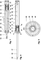
- the Figures 1 - 4 show a delay device (10), which is used for example in a guide system not shown here.
- This guide system carries and carries, for example, a drawer of a piece of furniture. It includes, in addition to the delay device (10), for example, a collection device.
- a collection device For example, when inserting the drawer surrounds before reaching the end position arranged on the drawer delay device (10) fixed in the piece of furniture driver. The lifting movement of the drawer relative to the piece of furniture is delayed.
- the collection device is triggered by means of the drawer.
- the feeder pulls against the action of the delay device (10) the drawer in the example closed end position.
- the delay device (10) remains in this case, for example, until reaching the end position in engagement with the driver.
- the use of a pneumatic retarding device (10) without a retraction device is also conceivable.
- the retarding device (10) comprises a cylinder (21) in which a piston unit (41) consisting of a piston (51) and a piston rod (42) is guided.
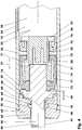
- the piston (51) carries two piston sealing elements (71, 72).
- the piston rod head (43) of e.g. largely cylindrical piston rod (42) is formed in this embodiment as a ball head (43). At this ball head (43), a driving element, a stop plate, etc. can be connected.
- the cylinder (21) comprises a pot-shaped cylinder jacket (22) with an integrated cylinder base (28) and a head part (29) closed by means of a piston rod seal (62). It is, for example, as injection molded thermoplastic parts, e.g. Polyoxymethylene, produced.
- the cylinder jacket (22) is cylindrical here on its outer side. Its length is for example five and a half times the diameter.
- the non-cylindrical cylinder inner wall (23) is e.g. formed in the shape of a truncated cone. The larger cross-sectional area of this truncated cone shell is located on the head part (29) of the cylinder (21), the smaller cross-sectional area on the cylinder bottom (28). The former cross-sectional area is e.g. 63 square millimeters. The slope of this Entformungskegels is for example 1:65.
- the inner wall (23) is optionally polished.
- the minimum wall thickness of the cylinder jacket (22) is e.g. 7% of its
- the cylinder bottom (28) has a frustoconical punch (31) projecting into the cylinder interior (25) and having a punch face (32). This limits together with the inner wall an annulus (33).
- the cross-sectional area of the annulus (33) is 80% of the larger cross-sectional area of the truncated cone shell. Its length is, for example, one-seventh of the piston stroke.
- the cylinder (21) can also be designed without a punch (31).
- a longitudinal groove (24) is arranged, see. FIG. 4 ,
- Their length is for example 60% of the cylinder length and ends depending on the design of the cylinder (21) in the plane of the punch face (32) or on the cylinder base (28).
- Their width is for example 2% of the larger diameter of the cylinder inner wall (23).
- the depth of the groove (24) is in this embodiment, a quarter of its width.
- the groove (24) is sharp-edged to the inner wall (23), the Nutauslauf has, for example, a slope of 45 degrees.
- a single groove (24) and a plurality of grooves (24) on the inner wall (23) may be arranged. These can also, for example, helically along the inner wall (23) of the cylinder jacket (22) along.
- the piston rod seal (62) has an outer support ring (63) and an inner sealing lip (64). It forms the piston rod leadthrough (61).
- the support ring (63) is non-sealingly against the piston rod (42).
- the outwardly facing sealing lip (64) engages around the piston rod (42) and seals in the in the FIG. 1 shown retracted piston position the cylinder interior (25) hermetically against the environment (1).
- a non-sealing stop ring (66) is oriented in the direction of the cylinder interior (25).
- the piston (51) and the piston rod (42) of the piston unit (41) are, for example, positively and materially connected to each other, they can be glued together.
- the overall length of the piston unit (41) is e.g. 5% longer than the length of the cylinder (21).
- the cross-sectional area of the piston rod (42), which is made of plastic for example, is one eighth of the internal cross section of the cylinder (21) on the cylinder head (29).
- the piston rod (42) may be bendable.
- the two piston sealing elements (71, 72) are arranged between a stop shoulder (45) of the piston unit (41) and a collar disk (56) oriented to the displacement space (15).
- the first piston sealing element (71) is cup-shaped. It sits firmly with a clamping area (73) between the piston rod (42) and the piston (51).
- An at least approximately cylindrical jacket-shaped collar region (74) adjoins this clamping region (73) and forms a deformation region (74).
- An inwardly projecting support ring (75) limits this piston sealing element (71) in the longitudinal direction (19). This support ring (75) is guided in a circumferential piston recess (52).
- the second sealing element (72) sits in the representation of FIG. 4 spaced from the first sealing element (71) in the piston recess (52). This is a direction in the direction of the displacement chamber (15) opened shaft seal (72) with an outer sealing collar (76).
- the piston sealing elements (71, 72) are made, for example, from nitrile butadiene rubber with a halogenated surface.
- the two piston sealing elements (71, 72) can also be designed as a common component.
- the total length of the unloaded, spaced-apart piston sealing elements (71, 72) is referred to below as the maximum length of the piston sealing elements (71, 72).
- the piston (51) has in the region of the piston recess (52) has two opposite longitudinal grooves (53) which are aligned with recesses (57) of the collar disc (56). These longitudinal grooves (53) connect the pressure chamber (17) of the first piston sealing element (71) with the displacement chamber (15).
- the piston rod (42) has longitudinal channels (48) in its lateral surface (47) in the section (46) adjoining the stop shoulder (45).
- the length of the e.g., the thickness of the cylinder head gasket (62) in a direction parallel to the piston rod (42) corresponds evenly to the longitudinal channels (48) distributed around the circumference.
- the length of the at least one longitudinal channel (48) corresponds, for example, to the length of the sealing lip (64) including its non-adjacent area (65).
- the longitudinal channel (48) projects out of the sealing lip (64) in the direction of the piston rod head (43). Its depth is for example 3% of the diameter of the piston rod (42), its width 16% of the piston rod diameter.
- the total cross section of the longitudinal channels (48) is thus 5% of the piston rod cross section.
- the piston rod (42) can also have spirally arranged channels (48). These can be the same or opposite, they can cut or penetrate, etc.
- the distance of the sealing lip (64) of the cylinder head gasket (62) to the beginning of the groove (24) in the cylinder inner wall (23) in the longitudinal direction (19) of the delay device (10) by three millimeters longer than the distance of the beginning of the longitudinal channels ( 48) to the displacement chamber side end of the sealing collar (76) of the second piston sealing element (72).
- the latter length is the sum of the length of the longitudinal channels (48), the length of a transition region (44) between the longitudinal channels (48) and the piston sealing elements (71, 72) and the maximum length of all piston sealing elements (71, 72).
- the displacement chamber (15).
- the piston (51) and the cylinder head (29) define a compensation chamber (16).
- the piston sealing element (71) and the piston (51) now delimit a pressure chamber (17), which communicates via the longitudinal grooves (53) and the recesses (57) with the displacement chamber (15).
- the piston (51) of the deceleration device (10) is extended, cf. Figures 2-4 , this is in the range of the larger inner diameter of the cylinder (21). For example, it lies in the groove-free, smooth region (26) of the cylinder inner wall (23).
- the sealing collar (76) non-sealingly contacts the cylinder inner wall (23).
- the sleeve portion (74) is undeformed with bilateral radial clearance between the cylinder inner wall (23) and the piston (51).
- the delay device (10) After installation in a piece of furniture, for example, when the drawer is extended, the delay device (10) out of engagement with the driver.
- the piston unit (51) is in their in the Figures 2-4 shown extended end position.
- the stop shoulder (45) abut the piston rod seal (62).
- the delay device (10) can also be designed such that in the extended end position of the piston unit (41) the stop shoulder (45), for example, by 2 to 3 millimeters spaced from the piston rod seal (62).
- a mechanical stop on the piston rod (42) outside or inside the cylinder (21) may be arranged.
- the piston rod (42) is retracted under the influence of the external force.
- the piston (51) is in this case from the cylinder head (29), see. Figure 2-4 , in the direction of the cylinder bottom (28), cf. FIG. 1 , postponed.
- the volume of the displacement chamber (15) - in the representation of Figures 2 and 4 this volume is maximum - diminished.
- the gas pressure for example the air pressure in the displacement chamber (15), increases and acts as an internal force on the piston sealing element (71).
- the sealing collar (76) is pressed against the cylinder inner wall (23) with deformation immediately at the beginning of the retraction movement of the piston rod (42).
- the displacement chamber (15) and the compensation chamber (16) are virtually hermetically isolated from each other.
- the compensation chamber (16) is hermetically sealed against the environment (1) by means of the piston rod seal (62). In the further retraction movement of the piston (51), a negative pressure is generated in the compensation chamber (16).
- the pressure that builds up in the displacement chamber (15) also acts on the inner surface of the brake collar (71).
- the Cuff area (74) is arched radially outward and pressed against the inner wall (23).
- the piston sealing element (71) is shortened in the axial direction.
- the support ring (75) travels along the e.g. frusto-conical piston recess (52) in the direction of the piston rod (42) and presses the deformation region (74) in addition radially outward, whereby the braking effect of the brake sleeve (71) is amplified.
- the connection channels (53, 57) are not interrupted, so that the displacement chamber (15) and the pressure chamber (17) communicate with each other during the entire stroke.
- the sealing collar (76) of the piston sealing element (72) reaches the beginning of the longitudinal groove (24).
- air is displaced from the displacement chamber (15) via the throttle channel (24) into the compensation chamber (16).
- the pressure in the displacement chamber (15) drops abruptly, for example.
- the brake sleeve (71) can still rest against the cylinder inner wall (23).
- the displaced from the displacement chamber (15) volume of air is greater than the volume by which the compensation chamber (16) is enlarged with the piston rod (42) penetrating it.
- the pressure in the compensation chamber (16) is increased. This air from the compensation chamber (16) by the against the environment (1) escape sealing piston rod seal (62) through into the environment (1).
- the drawer can couple with the collection device.
- the pressure in the displacement chamber (15) and in the compensation chamber (16) equalizes to the ambient pressure. There is no danger that in the rest position e.g. in material fatigue the delay device (10) bursts due to internal negative or positive pressure.
- the compensation chamber (16) is reduced and the displacement space (15) is increased. Due to the volume of the piston rod (42), the volume of the displaced air is smaller than the volume by which the displacement space (15) is increased. The air pressure in the displacement chamber (15) and in the compensation chamber (16) decreases.
- the displacement chamber (15) Shortly before reaching the extended end position of the piston unit (41) - the displacement chamber (15) has its maximum volume - the sealing lip (64) of the piston rod seal (62) reaches the at least one longitudinal groove (48) on the piston rod (42).
- a pneumatic connection (18) between the cylinder interior (25) and the environment (1) is opened. From the environment (1), air flows into the compensation chamber (16) and into the displacement chamber (15). The air pressure in these rooms (15, 16) is equal to the ambient pressure.
- the delay device (10) thus has a repeatable and constant performance.
- the elastically deformable piston rod (42) can be bent in the extended end position of the extended position.
- the piston rod seal (62) is deformed and leaking, so that for pressure equalization air from the environment (1) in the expansion chamber (16) and in the displacement chamber (15) can flow.
- the retarding device (10) can also be constructed such that the displacement space (15) is arranged between the piston (51) and the piston rod seal (62).
- the piston rod (42) penetrates the displacement chamber (15).
- the compensation chamber (16) is located between the piston (51) and the cylinder bottom (28).
- the delay device (10) described here may be part of a guidance system.
Landscapes
- Engineering & Computer Science (AREA)
- General Engineering & Computer Science (AREA)
- Mechanical Engineering (AREA)
- Actuator (AREA)
- Fluid-Damping Devices (AREA)
- Sealing Devices (AREA)
Claims (6)
- Dispositif d'amortissement pneumatique (10) comportant un cylindre (21) et un piston (51) guidé dans ce cylindre à l'aide d'une tige de piston (42) entourée d'une lèvre d'étanchéité (64) orientée vers une tête de tige de piston (43), comportant au moins un élément d'étanchéité du piston (71; 72) délimitant une chambre de refoulement (15) par rapport à une chambre de compensation (16), qui établit une force opposée à la course du piston (51) par surpression dans la chambre de refoulement (15) et par dépression dans la chambre de compensation (16), le courant de fuite entre la chambre de refoulement (15) et la chambre de compensation (16) dépendant au moins de la direction de la course
et l'élément d'étanchéité du piston (71; 72) isole la chambre de refoulement (15) et la chambre de compensation (16) quasi hermétiquement lors de la montée de la pression dans la chambre de refoulement (15),
caractérisé en ce- que le dispositif d'amortissement (10) présente une liaison pneumatique obturable (18) dans la position de fin de course du piston de la chambre maximale de refoulement (15), de sorte que la chambre de refoulement (15) et la chambre compensation (16), dans cette position finale, peuvent communiquer avec l'extérieur (1) à l'aide de cette liaison et- que le joint de la tige de piston (62), lorsque la liaison (18) est fermée, ferme l'espace intérieur du cylindre (25) hermétiquement contre l'espace extérieur (1) afin de produire la dépression dans la chambre de compensation (16). - Dispositif d'amortissement (10) selon la revendication 1, caractérisé en ce que la liaison pneumatique (18) est disposée dans le joint de la tige du piston (62) et/ou dans la tige du piston (42).
- Dispositif d'amortissement (10) selon la revendication 1, caractérisé en ce que la liaison pneumatique (18) est formée par au moins un canal longitudinal (42) disposé sur la tige du piston (42).
- Dispositif d'amortissement 10) selon la revendication 3, caractérisé en ce que la longueur du canal longitudinal (48) est inférieure à 5 % de la course du piston.
- Dispositif d'amortissement (10) selon la revendication 1, caractérisé en ce que le cylindre (21) a une paroi intérieure de cylindre (23) comportant au moins une rainure longitudinale (24) orientée dans le sens de la longueur (19), la longueur de la rainure longitudinale (24) étant au maximum de 90 % de la longueur du cylindre (21) et le piston (51) dans la position finale de l'espace de refoulement maximal (15) se trouvant dans une zone sans rainure (26) de la paroi intérieure du cylindre (23).
- Dispositif d'amortissement (10) selon les revendications 2, 4 et 5, caractérisé en ce que la somme de la longueur du canal longitudinal (48), de la longueur maximale de tous les éléments d'étanchéité de piston (71, 72) ainsi que de la longueur d'une zone de transition (44) est inférieure à la distance mesurée dans le sens longitudinal du joint monolèvre (64) par rapport à l'extrémité de la zone sans rainure (26) du côté chambre de refoulement de la paroi intérieur du cylindre (23).
Priority Applications (1)
| Application Number | Priority Date | Filing Date | Title |
|---|---|---|---|
| PL11809297T PL2585735T3 (pl) | 2010-06-24 | 2011-06-22 | Pneumatyczne urządzenie spowalniające o stałej sile działania |
Applications Claiming Priority (2)
| Application Number | Priority Date | Filing Date | Title |
|---|---|---|---|
| DE201010024994 DE102010024994B4 (de) | 2010-06-24 | 2010-06-24 | Pneumatische Verzögerungsvorrichtung mit konstanter Leistung |
| PCT/DE2011/001356 WO2012010136A2 (fr) | 2010-06-24 | 2011-06-22 | Dispositif ralentisseur pneumatique à puissance constante |
Publications (2)
| Publication Number | Publication Date |
|---|---|
| EP2585735A2 EP2585735A2 (fr) | 2013-05-01 |
| EP2585735B1 true EP2585735B1 (fr) | 2019-08-14 |
Family
ID=45115542
Family Applications (1)
| Application Number | Title | Priority Date | Filing Date |
|---|---|---|---|
| EP11809297.2A Active EP2585735B1 (fr) | 2010-06-24 | 2011-06-22 | Dispositif ralentisseur pneumatique à puissance constante |
Country Status (6)
| Country | Link |
|---|---|
| US (1) | US9127493B2 (fr) |
| EP (1) | EP2585735B1 (fr) |
| JP (1) | JP5826258B2 (fr) |
| DE (1) | DE102010024994B4 (fr) |
| PL (1) | PL2585735T3 (fr) |
| WO (1) | WO2012010136A2 (fr) |
Families Citing this family (8)
| Publication number | Priority date | Publication date | Assignee | Title |
|---|---|---|---|---|
| GB2498747B (en) * | 2012-01-24 | 2018-05-09 | Titus Int Ltd | Improvements in damper assemblies |
| EP3308059B1 (fr) * | 2015-06-15 | 2021-05-26 | Cummins, Inc. | Dispositif d'élasticité pour chambre de combustion |
| KR101783546B1 (ko) * | 2016-04-08 | 2017-09-29 | 홍정기 | 창호용 에어 댐퍼 |
| US11459812B2 (en) * | 2018-03-28 | 2022-10-04 | Piolax, Inc. | Damper |
| JP7444766B2 (ja) | 2020-12-18 | 2024-03-06 | 株式会社パイオラックス | ダンパー |
| JP7449885B2 (ja) * | 2021-02-15 | 2024-03-14 | 株式会社ニフコ | ダンパー装置 |
| WO2023171654A1 (fr) * | 2022-03-10 | 2023-09-14 | 株式会社パイオラックス | Dispositif amortisseur |
| US11959529B1 (en) * | 2023-08-14 | 2024-04-16 | Alfred Franklin Nibecker | Allow air springs to be self-charging |
Citations (2)
| Publication number | Priority date | Publication date | Assignee | Title |
|---|---|---|---|---|
| US5697477A (en) * | 1994-10-07 | 1997-12-16 | Nifco Inc. | Air damper |
| US20040032068A1 (en) * | 2002-08-19 | 2004-02-19 | Nifco Inc. | Damper |
Family Cites Families (15)
| Publication number | Priority date | Publication date | Assignee | Title |
|---|---|---|---|---|
| FR1588502A (fr) | 1968-06-28 | 1970-04-17 | ||
| DE2415204A1 (de) | 1973-04-03 | 1974-10-24 | Klein Ets Georges | Sperrvorrichtung, insbesondere fuer die beweglichen elemente von fensteroeffnungen, im besonderen fuer fahrzeuge, wie wohnwagenanhaenger oder dergleichen |
| DE2516478C3 (de) * | 1975-04-15 | 1978-12-07 | Suspa-Federungstechnik Fritz Bauer & Soehne Ohg, 8503 Altdorf | Gasfeder |
| JPS583160B2 (ja) * | 1976-03-19 | 1983-01-20 | トキコ株式会社 | 圧力容器へのガス封入方法 |
| JPS6035812Y2 (ja) * | 1979-11-09 | 1985-10-24 | トキコ株式会社 | ガススプリング |
| DE3301544A1 (de) * | 1983-01-19 | 1984-07-19 | Stabilus Gmbh, 5400 Koblenz | Gasfeder als huborgan zum oeffnen von nach oben schwenkbaren klappen |
| US4683992A (en) * | 1985-09-13 | 1987-08-04 | Ford Motor Company | Vehicle suspension damper with remote control |
| IT1210723B (it) * | 1987-05-11 | 1989-09-20 | Boge Italia Spa | Molla a gas a spinta variabile |
| DE3817776A1 (de) * | 1988-05-26 | 1989-12-07 | Bauer Fritz & Soehne Ohg | Gasfeder |
| DE4003245C2 (de) * | 1990-02-03 | 1997-08-21 | Stabilus Gmbh | Führung für teleskopartig ineinander verschiebbare zylindrische Teile |
| JPH08105482A (ja) * | 1994-10-07 | 1996-04-23 | Nifco Inc | エアダンパ |
| DE4442547C1 (de) | 1994-11-30 | 1996-06-05 | Daimler Benz Ag | Feststellvorrichtung für eine aufschwenkbare Fahrzeugklappe |
| DE20122569U1 (de) * | 2001-01-09 | 2006-04-27 | Julius Blum Gmbh | Brems- und Dämpfeinrichtung, insbesondere für bewegbare Möbel |
| DE10313659B3 (de) * | 2003-03-26 | 2004-09-30 | Zimmer, Günther Stephan | Pneumatische Verzögerungsvorrichtung zum Abbremsen beweglicher Möbelteile |
| DE102006040085A1 (de) * | 2006-08-28 | 2008-03-20 | Zimmer, Günther | Kostengünstig herstellbare pneumatische Verzögerungsvorrichtung |
-
2010
- 2010-06-24 DE DE201010024994 patent/DE102010024994B4/de not_active Expired - Fee Related
-
2011
- 2011-06-22 PL PL11809297T patent/PL2585735T3/pl unknown
- 2011-06-22 WO PCT/DE2011/001356 patent/WO2012010136A2/fr active Application Filing
- 2011-06-22 EP EP11809297.2A patent/EP2585735B1/fr active Active
- 2011-06-22 JP JP2013515692A patent/JP5826258B2/ja not_active Expired - Fee Related
-
2012
- 2012-12-16 US US13/716,157 patent/US9127493B2/en active Active
Patent Citations (2)
| Publication number | Priority date | Publication date | Assignee | Title |
|---|---|---|---|---|
| US5697477A (en) * | 1994-10-07 | 1997-12-16 | Nifco Inc. | Air damper |
| US20040032068A1 (en) * | 2002-08-19 | 2004-02-19 | Nifco Inc. | Damper |
Also Published As
| Publication number | Publication date |
|---|---|
| JP5826258B2 (ja) | 2015-12-02 |
| WO2012010136A2 (fr) | 2012-01-26 |
| US9127493B2 (en) | 2015-09-08 |
| JP2013531154A (ja) | 2013-08-01 |
| PL2585735T3 (pl) | 2020-02-28 |
| WO2012010136A3 (fr) | 2012-06-14 |
| US20130118846A1 (en) | 2013-05-16 |
| DE102010024994B4 (de) | 2012-06-14 |
| EP2585735A2 (fr) | 2013-05-01 |
| DE102010024994A1 (de) | 2011-12-29 |
Similar Documents
| Publication | Publication Date | Title |
|---|---|---|
| EP2585735B1 (fr) | Dispositif ralentisseur pneumatique à puissance constante | |
| DE10214596B4 (de) | Führungssystem mit pneumatischer Verzögerungsvorrichtung | |
| EP1606532B1 (fr) | Dispositif de deceleration pneumatique servant a reduire la vitesse de pieces de meubles mobiles | |
| EP2951458B1 (fr) | Unité cylindre-piston comprenant un étranglement de piston | |
| DE112014002401T5 (de) | Verriegelungsmechanismus für Motorhauben-Anhebeeinrichtungen für Fußgänger | |
| EP2057387B1 (fr) | Dispositif pneumatique de deceleration de fabrication economique | |
| EP2962022B1 (fr) | Soupape de trop-plein | |
| DE3825077A1 (de) | Laengeneinstellbare verstelleinrichtung | |
| DE102007060472A1 (de) | Zweiteiliger Kolben für einen Verbrennungsmotor | |
| DE112008002530B4 (de) | Nehmerzylinder und Ausrücksystem | |
| EP1662168B1 (fr) | Dispositif pneumatique de décélération pour le freinage | |
| WO2017190829A1 (fr) | Cylindre hydraulique, en particulier maître-cylindre d'un système de freinage hydraulique | |
| EP3458739A1 (fr) | Amortisseur de vibrations dont la force d'amortissement est fonction de la course | |
| EP1585909B1 (fr) | Systeme de guidage comportant un dispositif pneumatique de ralentissement | |
| DE102008010908B4 (de) | Kolbendichtelement und Verzögerungsvorrichtung mit Kolbendichtelement | |
| DE102005004195A1 (de) | Geberzylinder für hydraulische Betätigungssysteme | |
| DE1605326A1 (de) | Hydraulische Teleskopvorrichtung zur Beeinflussung der Geschwindigkeit von Schienenfahrzeugen ueber ihte Raeder | |
| DE2404111B2 (de) | Hydraulischer Einrohr-Stoßdämpfer | |
| DE102017106106A1 (de) | Dichtung für Kolben-Zylinder-Anordnung | |
| DE102015217789A1 (de) | Druckzylinder, insbesondere Geberzylinder, mit bewegter Dichtung sowie bewegter Hülse und variabler Ausrückkraft | |
| DE102012214713B4 (de) | Hydraulische Kolben-/Zylindereinheit | |
| DE2359751B2 (fr) | ||
| DE102016201386B4 (de) | Gasdruckfeder | |
| DE202005004719U1 (de) | Pneumatische Verzögerungseinrichtung zum Abbremsen beweglicher Möbelteile, insbesondere von Auszügen | |
| DE202022000256U1 (de) | Pneumatische Verzögerungsvorrichtung mit wiederverwertbaren Werkstoffen |
Legal Events
| Date | Code | Title | Description |
|---|---|---|---|
| PUAI | Public reference made under article 153(3) epc to a published international application that has entered the european phase |
Free format text: ORIGINAL CODE: 0009012 |
|
| 17P | Request for examination filed |
Effective date: 20130117 |
|
| AK | Designated contracting states |
Kind code of ref document: A2 Designated state(s): AL AT BE BG CH CY CZ DE DK EE ES FI FR GB GR HR HU IE IS IT LI LT LU LV MC MK MT NL NO PL PT RO RS SE SI SK SM TR |
|
| DAX | Request for extension of the european patent (deleted) | ||
| 17Q | First examination report despatched |
Effective date: 20140718 |
|
| GRAP | Despatch of communication of intention to grant a patent |
Free format text: ORIGINAL CODE: EPIDOSNIGR1 |
|
| STAA | Information on the status of an ep patent application or granted ep patent |
Free format text: STATUS: GRANT OF PATENT IS INTENDED |
|
| INTG | Intention to grant announced |
Effective date: 20190320 |
|
| GRAS | Grant fee paid |
Free format text: ORIGINAL CODE: EPIDOSNIGR3 |
|
| GRAA | (expected) grant |
Free format text: ORIGINAL CODE: 0009210 |
|
| STAA | Information on the status of an ep patent application or granted ep patent |
Free format text: STATUS: THE PATENT HAS BEEN GRANTED |
|
| AK | Designated contracting states |
Kind code of ref document: B1 Designated state(s): AL AT BE BG CH CY CZ DE DK EE ES FI FR GB GR HR HU IE IS IT LI LT LU LV MC MK MT NL NO PL PT RO RS SE SI SK SM TR |
|
| REG | Reference to a national code |
Ref country code: GB Ref legal event code: FG4D Free format text: NOT ENGLISH |
|
| REG | Reference to a national code |
Ref country code: CH Ref legal event code: EP Ref country code: AT Ref legal event code: REF Ref document number: 1167395 Country of ref document: AT Kind code of ref document: T Effective date: 20190815 |
|
| REG | Reference to a national code |
Ref country code: IE Ref legal event code: FG4D Free format text: LANGUAGE OF EP DOCUMENT: GERMAN |
|
| REG | Reference to a national code |
Ref country code: DE Ref legal event code: R096 Ref document number: 502011016008 Country of ref document: DE |
|
| REG | Reference to a national code |
Ref country code: NL Ref legal event code: FP |
|
| REG | Reference to a national code |
Ref country code: LT Ref legal event code: MG4D |
|
| PG25 | Lapsed in a contracting state [announced via postgrant information from national office to epo] |
Ref country code: FI Free format text: LAPSE BECAUSE OF FAILURE TO SUBMIT A TRANSLATION OF THE DESCRIPTION OR TO PAY THE FEE WITHIN THE PRESCRIBED TIME-LIMIT Effective date: 20190814 Ref country code: NO Free format text: LAPSE BECAUSE OF FAILURE TO SUBMIT A TRANSLATION OF THE DESCRIPTION OR TO PAY THE FEE WITHIN THE PRESCRIBED TIME-LIMIT Effective date: 20191114 Ref country code: BG Free format text: LAPSE BECAUSE OF FAILURE TO SUBMIT A TRANSLATION OF THE DESCRIPTION OR TO PAY THE FEE WITHIN THE PRESCRIBED TIME-LIMIT Effective date: 20191114 Ref country code: SE Free format text: LAPSE BECAUSE OF FAILURE TO SUBMIT A TRANSLATION OF THE DESCRIPTION OR TO PAY THE FEE WITHIN THE PRESCRIBED TIME-LIMIT Effective date: 20190814 Ref country code: HR Free format text: LAPSE BECAUSE OF FAILURE TO SUBMIT A TRANSLATION OF THE DESCRIPTION OR TO PAY THE FEE WITHIN THE PRESCRIBED TIME-LIMIT Effective date: 20190814 Ref country code: LT Free format text: LAPSE BECAUSE OF FAILURE TO SUBMIT A TRANSLATION OF THE DESCRIPTION OR TO PAY THE FEE WITHIN THE PRESCRIBED TIME-LIMIT Effective date: 20190814 Ref country code: PT Free format text: LAPSE BECAUSE OF FAILURE TO SUBMIT A TRANSLATION OF THE DESCRIPTION OR TO PAY THE FEE WITHIN THE PRESCRIBED TIME-LIMIT Effective date: 20191216 |
|
| PG25 | Lapsed in a contracting state [announced via postgrant information from national office to epo] |
Ref country code: RS Free format text: LAPSE BECAUSE OF FAILURE TO SUBMIT A TRANSLATION OF THE DESCRIPTION OR TO PAY THE FEE WITHIN THE PRESCRIBED TIME-LIMIT Effective date: 20190814 Ref country code: IS Free format text: LAPSE BECAUSE OF FAILURE TO SUBMIT A TRANSLATION OF THE DESCRIPTION OR TO PAY THE FEE WITHIN THE PRESCRIBED TIME-LIMIT Effective date: 20191214 Ref country code: LV Free format text: LAPSE BECAUSE OF FAILURE TO SUBMIT A TRANSLATION OF THE DESCRIPTION OR TO PAY THE FEE WITHIN THE PRESCRIBED TIME-LIMIT Effective date: 20190814 Ref country code: GR Free format text: LAPSE BECAUSE OF FAILURE TO SUBMIT A TRANSLATION OF THE DESCRIPTION OR TO PAY THE FEE WITHIN THE PRESCRIBED TIME-LIMIT Effective date: 20191115 Ref country code: AL Free format text: LAPSE BECAUSE OF FAILURE TO SUBMIT A TRANSLATION OF THE DESCRIPTION OR TO PAY THE FEE WITHIN THE PRESCRIBED TIME-LIMIT Effective date: 20190814 Ref country code: ES Free format text: LAPSE BECAUSE OF FAILURE TO SUBMIT A TRANSLATION OF THE DESCRIPTION OR TO PAY THE FEE WITHIN THE PRESCRIBED TIME-LIMIT Effective date: 20190814 |
|
| PG25 | Lapsed in a contracting state [announced via postgrant information from national office to epo] |
Ref country code: TR Free format text: LAPSE BECAUSE OF FAILURE TO SUBMIT A TRANSLATION OF THE DESCRIPTION OR TO PAY THE FEE WITHIN THE PRESCRIBED TIME-LIMIT Effective date: 20190814 |
|
| PG25 | Lapsed in a contracting state [announced via postgrant information from national office to epo] |
Ref country code: EE Free format text: LAPSE BECAUSE OF FAILURE TO SUBMIT A TRANSLATION OF THE DESCRIPTION OR TO PAY THE FEE WITHIN THE PRESCRIBED TIME-LIMIT Effective date: 20190814 Ref country code: DK Free format text: LAPSE BECAUSE OF FAILURE TO SUBMIT A TRANSLATION OF THE DESCRIPTION OR TO PAY THE FEE WITHIN THE PRESCRIBED TIME-LIMIT Effective date: 20190814 Ref country code: RO Free format text: LAPSE BECAUSE OF FAILURE TO SUBMIT A TRANSLATION OF THE DESCRIPTION OR TO PAY THE FEE WITHIN THE PRESCRIBED TIME-LIMIT Effective date: 20190814 |
|
| PG25 | Lapsed in a contracting state [announced via postgrant information from national office to epo] |
Ref country code: SK Free format text: LAPSE BECAUSE OF FAILURE TO SUBMIT A TRANSLATION OF THE DESCRIPTION OR TO PAY THE FEE WITHIN THE PRESCRIBED TIME-LIMIT Effective date: 20190814 Ref country code: SM Free format text: LAPSE BECAUSE OF FAILURE TO SUBMIT A TRANSLATION OF THE DESCRIPTION OR TO PAY THE FEE WITHIN THE PRESCRIBED TIME-LIMIT Effective date: 20190814 Ref country code: CZ Free format text: LAPSE BECAUSE OF FAILURE TO SUBMIT A TRANSLATION OF THE DESCRIPTION OR TO PAY THE FEE WITHIN THE PRESCRIBED TIME-LIMIT Effective date: 20190814 Ref country code: IS Free format text: LAPSE BECAUSE OF FAILURE TO SUBMIT A TRANSLATION OF THE DESCRIPTION OR TO PAY THE FEE WITHIN THE PRESCRIBED TIME-LIMIT Effective date: 20200224 |
|
| REG | Reference to a national code |
Ref country code: DE Ref legal event code: R097 Ref document number: 502011016008 Country of ref document: DE |
|
| PLBE | No opposition filed within time limit |
Free format text: ORIGINAL CODE: 0009261 |
|
| STAA | Information on the status of an ep patent application or granted ep patent |
Free format text: STATUS: NO OPPOSITION FILED WITHIN TIME LIMIT |
|
| PG2D | Information on lapse in contracting state deleted |
Ref country code: IS |
|
| 26N | No opposition filed |
Effective date: 20200603 |
|
| PG25 | Lapsed in a contracting state [announced via postgrant information from national office to epo] |
Ref country code: SI Free format text: LAPSE BECAUSE OF FAILURE TO SUBMIT A TRANSLATION OF THE DESCRIPTION OR TO PAY THE FEE WITHIN THE PRESCRIBED TIME-LIMIT Effective date: 20190814 |
|
| PGFP | Annual fee paid to national office [announced via postgrant information from national office to epo] |
Ref country code: NL Payment date: 20200707 Year of fee payment: 10 |
|
| PG25 | Lapsed in a contracting state [announced via postgrant information from national office to epo] |
Ref country code: MC Free format text: LAPSE BECAUSE OF FAILURE TO SUBMIT A TRANSLATION OF THE DESCRIPTION OR TO PAY THE FEE WITHIN THE PRESCRIBED TIME-LIMIT Effective date: 20190814 |
|
| REG | Reference to a national code |
Ref country code: CH Ref legal event code: PL |
|
| PG25 | Lapsed in a contracting state [announced via postgrant information from national office to epo] |
Ref country code: LU Free format text: LAPSE BECAUSE OF NON-PAYMENT OF DUE FEES Effective date: 20200622 |
|
| REG | Reference to a national code |
Ref country code: BE Ref legal event code: MM Effective date: 20200630 |
|
| PG25 | Lapsed in a contracting state [announced via postgrant information from national office to epo] |
Ref country code: CH Free format text: LAPSE BECAUSE OF NON-PAYMENT OF DUE FEES Effective date: 20200630 Ref country code: IE Free format text: LAPSE BECAUSE OF NON-PAYMENT OF DUE FEES Effective date: 20200622 Ref country code: LI Free format text: LAPSE BECAUSE OF NON-PAYMENT OF DUE FEES Effective date: 20200630 |
|
| PG25 | Lapsed in a contracting state [announced via postgrant information from national office to epo] |
Ref country code: BE Free format text: LAPSE BECAUSE OF NON-PAYMENT OF DUE FEES Effective date: 20200630 |
|
| REG | Reference to a national code |
Ref country code: AT Ref legal event code: MM01 Ref document number: 1167395 Country of ref document: AT Kind code of ref document: T Effective date: 20200622 |
|
| PG25 | Lapsed in a contracting state [announced via postgrant information from national office to epo] |
Ref country code: AT Free format text: LAPSE BECAUSE OF NON-PAYMENT OF DUE FEES Effective date: 20200622 |
|
| REG | Reference to a national code |
Ref country code: NL Ref legal event code: MM Effective date: 20210701 |
|
| PG25 | Lapsed in a contracting state [announced via postgrant information from national office to epo] |
Ref country code: NL Free format text: LAPSE BECAUSE OF NON-PAYMENT OF DUE FEES Effective date: 20210701 Ref country code: MT Free format text: LAPSE BECAUSE OF FAILURE TO SUBMIT A TRANSLATION OF THE DESCRIPTION OR TO PAY THE FEE WITHIN THE PRESCRIBED TIME-LIMIT Effective date: 20190814 Ref country code: CY Free format text: LAPSE BECAUSE OF FAILURE TO SUBMIT A TRANSLATION OF THE DESCRIPTION OR TO PAY THE FEE WITHIN THE PRESCRIBED TIME-LIMIT Effective date: 20190814 |
|
| PG25 | Lapsed in a contracting state [announced via postgrant information from national office to epo] |
Ref country code: MK Free format text: LAPSE BECAUSE OF FAILURE TO SUBMIT A TRANSLATION OF THE DESCRIPTION OR TO PAY THE FEE WITHIN THE PRESCRIBED TIME-LIMIT Effective date: 20190814 |
|
| PGFP | Annual fee paid to national office [announced via postgrant information from national office to epo] |
Ref country code: FR Payment date: 20230623 Year of fee payment: 13 |
|
| PGFP | Annual fee paid to national office [announced via postgrant information from national office to epo] |
Ref country code: IT Payment date: 20230629 Year of fee payment: 13 Ref country code: GB Payment date: 20230622 Year of fee payment: 13 |
|
| PGFP | Annual fee paid to national office [announced via postgrant information from national office to epo] |
Ref country code: DE Payment date: 20230720 Year of fee payment: 13 |
|
| PGFP | Annual fee paid to national office [announced via postgrant information from national office to epo] |
Ref country code: PL Payment date: 20240311 Year of fee payment: 14 |