EP2572901B1 - Bearing device for wheel - Google Patents
Bearing device for wheel Download PDFInfo
- Publication number
- EP2572901B1 EP2572901B1 EP11783512.4A EP11783512A EP2572901B1 EP 2572901 B1 EP2572901 B1 EP 2572901B1 EP 11783512 A EP11783512 A EP 11783512A EP 2572901 B1 EP2572901 B1 EP 2572901B1
- Authority
- EP
- European Patent Office
- Prior art keywords
- axle housing
- wheel
- seal ring
- annular groove
- wheel bearing
- Prior art date
- Legal status (The legal status is an assumption and is not a legal conclusion. Google has not performed a legal analysis and makes no representation as to the accuracy of the status listed.)
- Not-in-force
Links
Images


Classifications
-
- F—MECHANICAL ENGINEERING; LIGHTING; HEATING; WEAPONS; BLASTING
- F16—ENGINEERING ELEMENTS AND UNITS; GENERAL MEASURES FOR PRODUCING AND MAINTAINING EFFECTIVE FUNCTIONING OF MACHINES OR INSTALLATIONS; THERMAL INSULATION IN GENERAL
- F16C—SHAFTS; FLEXIBLE SHAFTS; ELEMENTS OR CRANKSHAFT MECHANISMS; ROTARY BODIES OTHER THAN GEARING ELEMENTS; BEARINGS
- F16C33/00—Parts of bearings; Special methods for making bearings or parts thereof
- F16C33/72—Sealings
- F16C33/76—Sealings of ball or roller bearings
- F16C33/78—Sealings of ball or roller bearings with a diaphragm, disc, or ring, with or without resilient members
- F16C33/7803—Sealings of ball or roller bearings with a diaphragm, disc, or ring, with or without resilient members suited for particular types of rolling bearings
- F16C33/7813—Sealings of ball or roller bearings with a diaphragm, disc, or ring, with or without resilient members suited for particular types of rolling bearings for tapered roller bearings
-
- B—PERFORMING OPERATIONS; TRANSPORTING
- B60—VEHICLES IN GENERAL
- B60B—VEHICLE WHEELS; CASTORS; AXLES FOR WHEELS OR CASTORS; INCREASING WHEEL ADHESION
- B60B27/00—Hubs
- B60B27/001—Hubs with roller-bearings
-
- B—PERFORMING OPERATIONS; TRANSPORTING
- B60—VEHICLES IN GENERAL
- B60B—VEHICLE WHEELS; CASTORS; AXLES FOR WHEELS OR CASTORS; INCREASING WHEEL ADHESION
- B60B27/00—Hubs
- B60B27/0073—Hubs characterised by sealing means
-
- B—PERFORMING OPERATIONS; TRANSPORTING
- B60—VEHICLES IN GENERAL
- B60B—VEHICLE WHEELS; CASTORS; AXLES FOR WHEELS OR CASTORS; INCREASING WHEEL ADHESION
- B60B27/00—Hubs
- B60B27/0078—Hubs characterised by the fixation of bearings
- B60B27/0084—Hubs characterised by the fixation of bearings caulking to fix inner race
-
- B—PERFORMING OPERATIONS; TRANSPORTING
- B60—VEHICLES IN GENERAL
- B60B—VEHICLE WHEELS; CASTORS; AXLES FOR WHEELS OR CASTORS; INCREASING WHEEL ADHESION
- B60B35/00—Axle units; Parts thereof ; Arrangements for lubrication of axles
- B60B35/12—Torque-transmitting axles
- B60B35/18—Arrangement of bearings
-
- F—MECHANICAL ENGINEERING; LIGHTING; HEATING; WEAPONS; BLASTING
- F16—ENGINEERING ELEMENTS AND UNITS; GENERAL MEASURES FOR PRODUCING AND MAINTAINING EFFECTIVE FUNCTIONING OF MACHINES OR INSTALLATIONS; THERMAL INSULATION IN GENERAL
- F16C—SHAFTS; FLEXIBLE SHAFTS; ELEMENTS OR CRANKSHAFT MECHANISMS; ROTARY BODIES OTHER THAN GEARING ELEMENTS; BEARINGS
- F16C19/00—Bearings with rolling contact, for exclusively rotary movement
- F16C19/22—Bearings with rolling contact, for exclusively rotary movement with bearing rollers essentially of the same size in one or more circular rows, e.g. needle bearings
- F16C19/34—Bearings with rolling contact, for exclusively rotary movement with bearing rollers essentially of the same size in one or more circular rows, e.g. needle bearings for both radial and axial load
- F16C19/38—Bearings with rolling contact, for exclusively rotary movement with bearing rollers essentially of the same size in one or more circular rows, e.g. needle bearings for both radial and axial load with two or more rows of rollers
- F16C19/383—Bearings with rolling contact, for exclusively rotary movement with bearing rollers essentially of the same size in one or more circular rows, e.g. needle bearings for both radial and axial load with two or more rows of rollers with tapered rollers, i.e. rollers having essentially the shape of a truncated cone
- F16C19/385—Bearings with rolling contact, for exclusively rotary movement with bearing rollers essentially of the same size in one or more circular rows, e.g. needle bearings for both radial and axial load with two or more rows of rollers with tapered rollers, i.e. rollers having essentially the shape of a truncated cone with two rows, i.e. double-row tapered roller bearings
- F16C19/386—Bearings with rolling contact, for exclusively rotary movement with bearing rollers essentially of the same size in one or more circular rows, e.g. needle bearings for both radial and axial load with two or more rows of rollers with tapered rollers, i.e. rollers having essentially the shape of a truncated cone with two rows, i.e. double-row tapered roller bearings in O-arrangement
-
- F—MECHANICAL ENGINEERING; LIGHTING; HEATING; WEAPONS; BLASTING
- F16—ENGINEERING ELEMENTS AND UNITS; GENERAL MEASURES FOR PRODUCING AND MAINTAINING EFFECTIVE FUNCTIONING OF MACHINES OR INSTALLATIONS; THERMAL INSULATION IN GENERAL
- F16C—SHAFTS; FLEXIBLE SHAFTS; ELEMENTS OR CRANKSHAFT MECHANISMS; ROTARY BODIES OTHER THAN GEARING ELEMENTS; BEARINGS
- F16C33/00—Parts of bearings; Special methods for making bearings or parts thereof
- F16C33/30—Parts of ball or roller bearings
- F16C33/58—Raceways; Race rings
- F16C33/583—Details of specific parts of races
- F16C33/586—Details of specific parts of races outside the space between the races, e.g. end faces or bore of inner ring
-
- F—MECHANICAL ENGINEERING; LIGHTING; HEATING; WEAPONS; BLASTING
- F16—ENGINEERING ELEMENTS AND UNITS; GENERAL MEASURES FOR PRODUCING AND MAINTAINING EFFECTIVE FUNCTIONING OF MACHINES OR INSTALLATIONS; THERMAL INSULATION IN GENERAL
- F16C—SHAFTS; FLEXIBLE SHAFTS; ELEMENTS OR CRANKSHAFT MECHANISMS; ROTARY BODIES OTHER THAN GEARING ELEMENTS; BEARINGS
- F16C33/00—Parts of bearings; Special methods for making bearings or parts thereof
- F16C33/72—Sealings
- F16C33/76—Sealings of ball or roller bearings
- F16C33/768—Sealings of ball or roller bearings between relatively stationary parts, i.e. static seals
-
- F—MECHANICAL ENGINEERING; LIGHTING; HEATING; WEAPONS; BLASTING
- F16—ENGINEERING ELEMENTS AND UNITS; GENERAL MEASURES FOR PRODUCING AND MAINTAINING EFFECTIVE FUNCTIONING OF MACHINES OR INSTALLATIONS; THERMAL INSULATION IN GENERAL
- F16C—SHAFTS; FLEXIBLE SHAFTS; ELEMENTS OR CRANKSHAFT MECHANISMS; ROTARY BODIES OTHER THAN GEARING ELEMENTS; BEARINGS
- F16C35/00—Rigid support of bearing units; Housings, e.g. caps, covers
- F16C35/04—Rigid support of bearing units; Housings, e.g. caps, covers in the case of ball or roller bearings
- F16C35/06—Mounting or dismounting of ball or roller bearings; Fixing them onto shaft or in housing
- F16C35/067—Fixing them in a housing
-
- B—PERFORMING OPERATIONS; TRANSPORTING
- B60—VEHICLES IN GENERAL
- B60B—VEHICLE WHEELS; CASTORS; AXLES FOR WHEELS OR CASTORS; INCREASING WHEEL ADHESION
- B60B2380/00—Bearings
- B60B2380/10—Type
- B60B2380/14—Roller bearings
-
- B—PERFORMING OPERATIONS; TRANSPORTING
- B60—VEHICLES IN GENERAL
- B60B—VEHICLE WHEELS; CASTORS; AXLES FOR WHEELS OR CASTORS; INCREASING WHEEL ADHESION
- B60B2380/00—Bearings
- B60B2380/70—Arrangements
- B60B2380/73—Double track
-
- B—PERFORMING OPERATIONS; TRANSPORTING
- B60—VEHICLES IN GENERAL
- B60B—VEHICLE WHEELS; CASTORS; AXLES FOR WHEELS OR CASTORS; INCREASING WHEEL ADHESION
- B60B2900/00—Purpose of invention
- B60B2900/20—Avoidance of
- B60B2900/211—Soiling
-
- B—PERFORMING OPERATIONS; TRANSPORTING
- B60—VEHICLES IN GENERAL
- B60B—VEHICLE WHEELS; CASTORS; AXLES FOR WHEELS OR CASTORS; INCREASING WHEEL ADHESION
- B60B2900/00—Purpose of invention
- B60B2900/50—Improvement of
- B60B2900/511—Sealing
- B60B2900/5112—Sealing against dust or dirt
-
- B—PERFORMING OPERATIONS; TRANSPORTING
- B60—VEHICLES IN GENERAL
- B60Y—INDEXING SCHEME RELATING TO ASPECTS CROSS-CUTTING VEHICLE TECHNOLOGY
- B60Y2200/00—Type of vehicle
- B60Y2200/10—Road Vehicles
- B60Y2200/11—Passenger cars; Automobiles
-
- F—MECHANICAL ENGINEERING; LIGHTING; HEATING; WEAPONS; BLASTING
- F16—ENGINEERING ELEMENTS AND UNITS; GENERAL MEASURES FOR PRODUCING AND MAINTAINING EFFECTIVE FUNCTIONING OF MACHINES OR INSTALLATIONS; THERMAL INSULATION IN GENERAL
- F16C—SHAFTS; FLEXIBLE SHAFTS; ELEMENTS OR CRANKSHAFT MECHANISMS; ROTARY BODIES OTHER THAN GEARING ELEMENTS; BEARINGS
- F16C2240/00—Specified values or numerical ranges of parameters; Relations between them
- F16C2240/40—Linear dimensions, e.g. length, radius, thickness, gap
- F16C2240/42—Groove sizes
-
- F—MECHANICAL ENGINEERING; LIGHTING; HEATING; WEAPONS; BLASTING
- F16—ENGINEERING ELEMENTS AND UNITS; GENERAL MEASURES FOR PRODUCING AND MAINTAINING EFFECTIVE FUNCTIONING OF MACHINES OR INSTALLATIONS; THERMAL INSULATION IN GENERAL
- F16C—SHAFTS; FLEXIBLE SHAFTS; ELEMENTS OR CRANKSHAFT MECHANISMS; ROTARY BODIES OTHER THAN GEARING ELEMENTS; BEARINGS
- F16C2326/00—Articles relating to transporting
- F16C2326/01—Parts of vehicles in general
- F16C2326/02—Wheel hubs or castors
Definitions
- the present invention relates to a wheel bearing apparatus for rotatably supporting a wheel of a vehicle such as an automobile relative to a suspension apparatus of the vehicle, and more particularly to a wheel bearing apparatus of a semi-floating type in which a driving wheel is supported by a double row rolling bearing.
- a vehicle such as a truck having a body of a frame structure
- an axle structure of a full-floating type driving wheel has been widely adopted.
- a double row rolling bearing unit structure has been widely adopted so as to improve the readiness of assembly, reduction of weight and size.
- Fig. 6 One example of such a semi-floating type wheel bearing apparatus of the prior art is shown in Fig. 6 .
- double row rolling bearing 52 has an outer member 54 formed with, in its inner circumference, double row tapered outer raceway surfaces 54a, 54a, and in its outer circumference, a body mounting flange 54b which is fixed to an axle housing H; a pair of inner rings 60, 60, which is inserted in the outer member 54 and in which a tapered inner raceway surface 60a is formed opposite to the double row outer raceway surfaces 54a, 54a in its outer circumference; and double row conical rollers 55, 55 which are rollably accommodated between both raceway surfaces 54a, 60a.
- the pair of inner rings 60, 60 are press-fitted in the cylindrical portion 57 formed in the outer circumference of the wheel hub 51.
- a cap 61 is press-fitted in an opening of the wheel hub 51.
- the cap 61 is configured of a metal core 61a made of a steel plate which is press-formed as having a substantially "C"-shaped cross-section of an austenitic-stainless steel sheet (JIS SUS 304 etc.) or preserved cold rolled steel sheet (JIS SPCC etc.), and an elastic member 61b of a rubber bonded via vulcanization to at least the fitting portion of the metal core 61a.
- the elastic member 61b is elastically deformed into the fitting surface to fluid-tightly seal the inside thereof.
- the cap 61 almost uninfluenced by the elastic deformation of the wheel hub 51 even though the wheel hub 51 repeatedly receives a moment load and is elastic deformed when driving the vehicle (for example, see Patent Literature 1).
- Patent Document 1 Japanese Laid-open Patent Publication No. 2005-297944 .
- an object of the present invention to provide a wheel bearing apparatus which can prevent penetration of rain water or dust and leakage of differential gear oil so that the sealing effect is increased and reliability is ensured over the long term.
- a wheel bearing apparatus includes: an axle housing into which a driving shaft connecting to a differential gear is inserted and which is supported on the lower surface of a vehicle body; a wheel hub which is joined to the driving shaft and integrally has a wheel mounting flange for attaching a wheel and in which a cylindrical portion extending in an outer circumference in an axial direction; a wheel bearing which is fitted between the cylindrical portion of the wheel hub and an opening of the axle housing and rotatably supports the wheel; an outer member in which the wheel bearing integrally has a body mounting flange to be attached to the axle housing in the outer circumference and a pilot portion fitted into the axle housing at an end portion of an inner side, and double row outer raceway surfaces are integrally formed in the inner circumference; an inner member which is press-fitted in the cylindrical portion of the wheel hub and configured of at least one inner ring in which inner raceway surfaces are formed opposite to the double row outer raceway surfaces; double row rolling bodies which are
- the wheel bearing apparatus including the axle housing which is inserted in the driving shaft connecting the differential gear and is supported on the lower surface of the vehicle body; the wheel hub integrally having the wheel mounting flange; and wheel bearing which is configured of double row rolling bearing fitted between the wheel hub and the opening of the axle housing, the annular groove is formed at the pilot portion of the outer member, the seal ring, which is formed of the synthetic rubber, is mounted in the annular groove and elastically contacts the axle housing, and a slight gap of the fitting portion between the outer member and the axle housing is blocked off so that the wheel bearing apparatus can be provided which can prevent penetration of rain water or dust and leakage of differential gear oil so that sealing effect is increased and reliability is ensured over the long term.
- the assembly of the bearing portion to the axle housing is easily performed and the assembly work can be simplified and readiness of assembly of the bearing portion to the axle housing is improved. Also, when the bearing portion is assembled to the axle housing, it is possible to prevent the seal ring being bitten by the axle housing due to the seal ring bends.
- an outer diameter of the seal ring after mounting be set to be smaller than the inner diameter of the cylindrical portion of the axle housing. Accordingly, when the bearing portion is assembled to the axle housing, it is possible to reliably prevent the seal ring being bitten into by the axle housing.
- the annular groove be formed with a substantially rectangular cross-section and a corner R in a near side of the outer raceway surface in corners R of the annular groove be set to be larger than a corner R in a far side thereof. Accordingly, since the distance from the outer raceway surface is larger than that of the same corner R substantially, it is advantageous with respect to the heat treatment deformation and when the bending load is repeatedly applied, the strength is increased and the durability can be improved.
- the annular groove be formed in substantially semi-circular cross-section and the groove bottom portion have a single radius of curvature. Accordingly, the annular groove is subject to almost not thermal influence due to the quenching and decrease in the strength due to cut-out effect can be suppressed.
- a compression set in the rubber material values of the seal ring be 40 % or less in 120°C x 70 hours and TR10 value (elongation rate 50 %) is -20°C or less. Accordingly, the distortion recovery characteristic is satisfactory even in a low temperature region and desired sealing effect can be maintained.
- a color of the seal ring be set as a warm color. Accordingly, when assembling, forgetting to mount or overlooking confirmation of the mounting of the seal ring can be prevented and the assembly work can be simplified.
- the same grease as enclosed inside the bearing be coated on the seal ring beforehand and the seal ring be mounted in a state where the grease is attached to its surface. Accordingly, mounting ability of the seal ring can be improved and the bearing portion can be smoothly fitted in the axle housing without bending even though the seal ring contacts the axle housing when assembling.
- the seal ring be selected from hydrogenation acrylonitrile-butadiene rubber, ethylene propylene rubber, polyacrylic rubber, fluorine rubber or silicon rubber. Accordingly, the seal ring is excellent in heat resistance and in chemical resistance and durability thereof can be improved.
- the wheel bearing apparatus of the present invention includes: an axle housing into which a driving shaft connecting to a differential gear is inserted and which is supported on the lower surface of a vehicle body; a wheel hub which is joined to the driving shaft and integrally has a wheel mounting flange for attaching a wheel and in which a cylindrical portion extending in an outer circumference in an axial direction; a wheel bearing which is fitted between the cylindrical portion of the wheel hub and an opening of the axle housing and rotatably supports the wheel; an outer member in which the wheel bearing integrally has a body mounting flange to be attached to the axle housing in the outer circumference and a pilot portion fitted into the axle housing at an end portion of an inner side, and double row outer raceway surfaces are integrally formed in the inner circumference; an inner member which is press-fitted in the cylindrical portion of the wheel hub and configured of at least one inner ring in which inner raceway surfaces are formed opposite to the double row outer raceway surfaces; double row rolling bodies which are rollably accommodated between the inner member and both raceway surfaces of the outer member
- the semi-floating type wheel bearing apparatus includes: an axle housing into which a driving shaft connecting to a differential gear is inserted and which is supported on the lower surface of a vehicle body; a wheel hub which is joined to the driving shaft via serration and integrally has a wheel mounting flange for attaching a wheel and in which a cylindrical portion extending in an outer circumference in an axial direction is formed; a wheel bearing which is fitted between the cylindrical portion of the wheel hub and an opening of the axle housing and rotatably supports the wheel; an outer member in which the wheel bearing integrally has a body mounting flange to be attached to the axle housing in the outer circumference and a pilot portion fitted into the axle housing at an end portion of an inboard side, and double row outer raceway surfaces are integrally formed in the inner circumference; a pair of inner rings in which an inner raceway surface is formed opposite to the double row outer raceway surface at the outer circumference; double row rolling bodies which are rollably accommodated between the pair of inner rings and both raceway surfaces of the outer member via a cage;
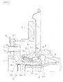
- Fig. 1 is a longitudinal-section view of around an underbody of an embodiment of a wheel bearing apparatus
- Fig. 2 is a longitudinal-section view illustrating the wheel bearing apparatus in Fig. 1
- Fig. 3(a) is an enlarged view of a main portion of Fig. 2
- Fig. 3(b) is a partially enlarged view of Fig. 3(a)
- Fig. 4(a) is an enlarged view of the present invention showing a main portion illustrating a modification example of Fig. 3(a)
- Fig. 4(b) is a cross-sectional view illustrating a seal ring unit of Fig. 4(a)
- Fig. 5(a) is a partially enlarged view of Fig.
- Fig. 5(b) is a partially enlarged view illustrating a modification example of Fig. 5(a) .
- a side of a bearing positioned to the outside of a vehicle when it is mounted on a vehicle is referred to as the "outboard" side (the left side in Fig. 1 )
- a side of the bearing positioned to the center of the vehicle is referred to as "inboard” side (the right side in Fig. 1 ).
- the semi-floating type wheel bearing apparatus is configured of a wheel hub 1 and double row rolling bearing 2 as a unit and is connected to the driving shaft D/S.
- the double row rolling bearing 2 includes an inner member 3, an outer member 4 and double row rolling bodies (conical rollers) 5, 5 which are rollably accommodated between both members 3, 4.
- the inner member 3 means the wheel hub 1, and a pair of inner rings 10, 10 press-fitted in the wheel hub 1.
- the wheel hub 1 integrally has a wheel mounting flange 6 for attaching the wheel W and a brake rotor B at an end portion of the outboard side.
- a cylindrical portion 7 extending from the wheel mounting flange 6 in its outer circumference in the axial direction and a serrations (or a spline) 8 in its inner circumference thereof are formed.
- the driving shaft D/S is inserted via the serrations 8.
- the wheel hub 1 and the driving shaft D/S are joined with freely transmitting the torque and removably.
- the double row rolling bearing 2 includes the outer member 4 formed with double row tapered outer raceway surfaces 4a, 4a on its inner circumference and with a vehicle body mounting flange 4b to be secured in an axle housing 14 on its outer circumference; a pair of inner rings 10, 10 inserted in the outer member 4 and formed with tapered inner raceway surfaces 10a on its outer circumference opposite to the double row outer raceway surfaces 4a, 4a; double row rolling bodies 5, 5 accommodated between both raceway surfaces 4a, 10a; and a cage 11 for rollably holding the double row rolling bodies 5, 5.
- a pair of inner rings 10, 10 is formed with, at a larger diameter side of the inner raceway surface 10a, a large flange 10b for guiding the rolling body 5, and a small flange 10c for preventing from being removed of the rolling body 5 at the small diameter side.
- the pair of inner rings 10, 10 are arranged so that their forward ends abut each other and thus form a so-called back-abutted type double row conical roller bearing.
- Seals 12, 12 are mounted at the openings of an annular space formed between the outer member 4 and inner ring 10.
- the seals 12, 12 prevent leakage of lubricating grease sealed within the bearing to the outside and penetration of rain water or dust from the external environments into the bearing.
- the inboard side seal 12 further prevents penetration or penetration of differential gear oil into the inside of the bearing via the serration 8 of the wheel hub 1.
- the pair of inner rings 10, 10 are press-fitted onto the cylindrical portion 7 of the wheel hub 1 via a predetermined interference and the inner rings 10, 10 are fixed to the wheel hub 1 in the axial direction by a caulked portion 13 formed by plastically deforming the end of the cylindrical portion 7 radially outward, in a state where the preload of the bearing is provided. Since this embodiment adopts the self-retaining structure of the second generation, it is not required to control the amount of preload as in a conventional manner by tightly fastening a nut or the like against the inner ring. Accordingly, it is possible to substantially reduce the number of parts and thus to improve the readiness of assembly and maintain the amount of preload over the long term as well as to reduce its manufacturing cost, weight and size.
- the wheel hub 1 is made of medium and high carbon steel such as S53C including carbon of 0.40 to 0.80% by weight and hardened by high frequency induction quenching so that the double row rolling bearing 2 has the surface hardness of 50 to 64 HRC (the hardened portion is shown in drawings by cross-hatched lines) from the shoulder portion 1a through the cylindrical portion 7.
- the caulked portion 13 remains as an unhardened portion having its surface hardness of 25 HRC or less. This improves the durability and workability of the caulked portion 13 during plastic deformation, and also prevents generation of cracks therein and then the reliability of the quality thereof is improved.
- the outer member 4 is also made of medium and high carbon steel such as S53C including carbon of 0.40 to 0.80% by weight and at least the double row outer raceway surfaces 4a, 4a are hardened by high frequency induction quenching so that their surface hardness is in a range of 58 to 64 HRC.
- the inner rings 10 and the rolling body 5 are made of a high carbon chrome bearing steel such as SUJ2 and hardened to its core by dipping quenching to have a surface hardness of HRC 60 to 64.
- a double row conical roller bearing using tapered roller as rolling bodies 5, 5 a double row angular ball bearing using balls may be also used.
- the present invention is not limited to the description and may be the wheel bearing apparatus configured of the third generation structure wherein the inner raceway surface is formed directly on the outer circumference of the wheel hub even though not illustrated.
- a cap 9 is press-fitted into an opening of the wheel hub 1 at its outboard side.
- the cap 9 is configured of a metal core 9a made of a steel plate which is press-formed as having a substantially "C"-shaped cross-section of an austenitic-stainless steel sheet (JIS SUS 304 etc.) or preserved cold rolled steel sheet (JIS SPCC etc.), and an elastic member 9b of a synthetic rubber bonded via vulcanization to at least the fitting portion of the metal core 9a.
- the elastic member 9b is elastically deformed in the fitting surface to fluid-tightly seal the inside thereof. Accordingly, it is possible to prevent leakage of the differential gear oil to outside and penetration of rain water or dust from the outside into the driving shaft and thus to mix into the differential gear oil.
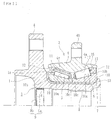
- a pilot portion 15 of the outer member 4 is configured of a cylindrical portion 15a extending from the body mounting flange 4b in the axial direction and a tapered portion 15b which gradually decreases in diameter from the cylindrical portion 15a to an end surface of the inboard side.
- the fitting portion 16 of the axle housing 14 is also configured of a cylindrical portion 16a along the cylindrical portion 15a and a tapered portion 16b gradually decreasing in its diameter from the cylindrical portion 16a to the inboard side corresponding to the shape of the pilot portion 15 of the outer member 4.
- the double row rolling bearing 2 is fitted in the axle housing 14, in a state where the brake cover B/C is clamped. Accordingly, the assembly of the bearing portion to the axle housing 14 is easily performed and the assembly work is simplified, and the airtight of the fitting portion of the bearing portion with the axle housing increases.
- annular groove 17 having a rectangular cross-section is formed at the cylindrical portion 15a of the pilot portion 15 and a seal ring 18 having a circular cross-section is mounted in the annular groove 17.
- the seal ring 18 is formed of a synthetic rubber such as NBR, elastically contacts the axle housing 14 and cuts off a slight gap of the fitting portion between the outer member 4 and the axle housing 14. Accordingly, the penetration of rainwater or dust and leakage of the differential gear oil are prevented so that the wheel bearing apparatus may be provided in which the sealing effect is increased and the reliability is ensured over the long term.
- the material of the seal ring 18 includes for example, HNBR (hydrogenation acrylonitrile-butadiene rubber), EPDM (ethylene propylene rubber), ACM (polyacrylic rubber) or FKM (fluorine rubber) or silicon rubber which are excellent in heat resistance besides NBR.
- HNBR hydrogenation acrylonitrile-butadiene rubber
- EPDM ethylene propylene rubber
- ACM polyacrylic rubber
- FKM fluorine rubber
- silicon rubber which are excellent in heat resistance besides NBR.
- ACM, FKM, EPDM and silicon rubber having excellent heat resistance and chemical resistance are preferable for the use to contact this type of differential gear oil.
- the seal ring 18 is used in which the compression set in the rubber material values is 40 % or less in 120°C x 70 hours and TR10 value (elongation rate 50 %) is -20°C or less. Accordingly, the distortion recovery characteristic is satisfactory even in a low temperature region and desired sealing effect can be maintained.
- the TR10 value means the temperature when the distortion that is given beforehand is recovered by 10 % and near the value is empirically used as a low temperature limit value of the rubber material.
- the inner diameter of the seal ring 18 before mounting is set to be smaller than the diameter of the bottom of the annular groove 17. Accordingly, the interference is present when the seal ring 18 is mounted. It is possible to prevent the seal ring 18 bending and then being bitten by the axle housing 14, when the bearing portion is assembled in the axle housing 14.
- the annular groove is formed at the axle housing and the seal ring is mounted in the annular groove beforehand. However, in this case, it is not preferable because there is concern that when the bearing portion is assembled at the axle housing, the seal ring may contact the outer member and may be removed from the annular groove and then be bitten.
- a predetermined hardened layer 19 is formed at the double row outer raceway surface 4a of the outer member 4 by high frequency induction quenching (the hardened portion is shown in drawings by cross-hatched lines) and an effective hardened layer depth of the hardened layer 19 is set to be in a range of 2 to 4.5 mm.
- the annular groove 17 is arranged so that the shortest distance L between the annular groove 17 where the seal ring 18 is mounted and the outer raceway surface 4a is 4.5 mm or more. Accordingly, the annular groove 17 is not subject to thermal influence due to the quenching and its heat-treatment deformation can be prevented, and then decrease in the strength due to annealing or the like can be prevented and then the reliability can be improved.
- the color of the seal ring 18 is set as a warm color such as red, yellow, orange, the yellow green. Accordingly, when assembling, forgetting to mount or overlooking confirmation of the mounting of the seal ring 18 can be prevented and the assembly work can be simplified.
- seal ring 18 is coated on the seal ring 18 beforehand which is the same grease as enclosed inside the bearing and the seal ring 18 is mounted in a state where the grease is attached to its surface. Accordingly, mounting ability of the seal ring 18 can be improved and the bearing portion can be smoothly fitted in the axle housing 14 without bending even though the seal ring 18 contacts the axle housing 14 when assembling.
- a pilot portion 21 of an outer member 20 is configured of a cylindrical portion 21a extending from the body mounting flange 4b in the axial direction and a tapered portion 21b gradually decreasing in its diameter from the cylindrical portion 21a to the end surface of the inboard side.
- the outer member 20 is fitted in the axle housing 14 in a state where the brake cover B/C is clamped.
- an annular groove 22 having a rectangular cross-section is formed at the tapered portion 21b of the pilot portion 21 and a seal ring 23 having a circular cross-section is mounted in the annular groove 22.
- the seal ring 23 is formed of ACM, and is molded having a substantially circular cross-section and is elastically contacts the tapered portion 16b of the axle housing 14.
- the inner diameter d2 of the seal ring 23 unit is set to be smaller (d2 ⁇ d1) than the groove bottom diameter d1 and the outer diameter d3 of the seal ring 23 after mounting is set to be smaller (d3 ⁇ d4) than the inner diameter d4 of the cylindrical portion 16a of the axle housing 14. Accordingly, when the bearing portion is assembled in the axle housing 14, it is possible to reliably prevent the seal ring 23 being bitten by the axle housing 14.
- a predetermined hardened layer 19 is formed at the double row outer raceway surface 4a of the outer member 20 by high frequency induction quenching (the hardened portion is shown in drawings by cross-hatched lines) and an effective hardened layer depth of the hardened layer 19 is set to be in a range of 2 to 4.5 mm.
- the annular groove 22 is arranged so that the shortest distance L between the annular groove 22 where the seal ring 23 is mounted and the outer raceway surface 4a is 4.5 mm or more. Accordingly, the annular groove 22 is not subject to thermal influence due to the quenching and its heat-treatment deformation can be prevented, and simultaneously decrease in the strength due to annealing or the like can be prevented and then the reliability can be improved.
- An outer member 24 of Fig. 5(b) is a modification example of the outer member 20 of Fig. 5(a) .
- An annular groove 25, in which the seal ring 23 is mounted, is formed at the tapered portion 21b of the pilot portion 21.
- the annular groove 25 having a substantially semi-circular cross-section is configured such that the shape of the groove bottom portion is formed with a single radius of curvature R0. Accordingly, the annular groove 25 is subject to nearly no thermal influence to the quenching and decrease in the strength due to cut-out effect can be suppressed.
- the wheel bearing apparatus of the present invention can be applied to the wheel bearing apparatus of the semi-floating type in which the wheel bearing is mounted at the opening of the axle housing and the driving shaft, and the wheel of the vehicle is rotatably supported.
Applications Claiming Priority (2)
| Application Number | Priority Date | Filing Date | Title |
|---|---|---|---|
| JP2010112824A JP5560090B2 (ja) | 2010-05-17 | 2010-05-17 | 車輪用軸受装置 |
| PCT/JP2011/061234 WO2011145578A1 (ja) | 2010-05-17 | 2011-05-16 | 車輪用軸受装置 |
Publications (3)
| Publication Number | Publication Date |
|---|---|
| EP2572901A1 EP2572901A1 (en) | 2013-03-27 |
| EP2572901A4 EP2572901A4 (en) | 2014-11-26 |
| EP2572901B1 true EP2572901B1 (en) | 2017-08-09 |
Family
ID=44991681
Family Applications (1)
| Application Number | Title | Priority Date | Filing Date |
|---|---|---|---|
| EP11783512.4A Not-in-force EP2572901B1 (en) | 2010-05-17 | 2011-05-16 | Bearing device for wheel |
Country Status (5)
| Country | Link |
|---|---|
| US (1) | US8777492B2 (ja) |
| EP (1) | EP2572901B1 (ja) |
| JP (1) | JP5560090B2 (ja) |
| CN (1) | CN102939208B (ja) |
| WO (1) | WO2011145578A1 (ja) |
Families Citing this family (11)
| Publication number | Priority date | Publication date | Assignee | Title |
|---|---|---|---|---|
| JP2015010681A (ja) * | 2013-07-01 | 2015-01-19 | 株式会社ジェイテクト | 軸受ユニット |
| JP2017082945A (ja) * | 2015-10-29 | 2017-05-18 | Ntn株式会社 | 複列円すいころ軸受、軌道輪および複列円すいころ軸受の製造方法 |
| ITUB20160674A1 (it) * | 2016-02-11 | 2017-08-11 | Fpt Ind Spa | Mozzo ruota con sistema di tenuta migliorato |
| IT201700058071A1 (it) * | 2017-05-29 | 2018-11-29 | Skf Ab | Gruppo cuscinetto mozzo-ruota |
| JP6936695B2 (ja) | 2017-10-24 | 2021-09-22 | Ntn株式会社 | 車輪用軸受装置とその製造方法 |
| US20230003256A1 (en) * | 2017-10-24 | 2023-01-05 | Ntn Corporation | Wheel bearing device and method for manufacturing said device |
| DE102017222310A1 (de) * | 2017-12-08 | 2019-06-13 | Aktiebolaget Skf | Radlagereinheit und Vormontageverfahren |
| DE102019212595A1 (de) * | 2018-09-07 | 2020-03-12 | Aktiebolaget Skf | Dichtungsvorrichtung für eine Radlagereinheit |
| DE102019212747A1 (de) * | 2018-09-10 | 2020-04-30 | Aktiebolaget Skf | Dichtungsvorrichtung für eine Radlagereinheit |
| JP7441609B2 (ja) * | 2019-03-25 | 2024-03-01 | Ntn株式会社 | 車輪用軸受装置 |
| IT202000026608A1 (it) | 2020-11-09 | 2022-05-09 | Skf Ab | Unita’ cuscinetto in acciaio a basso teneore di carbonio |
Family Cites Families (29)
| Publication number | Priority date | Publication date | Assignee | Title |
|---|---|---|---|---|
| US3854735A (en) * | 1972-10-24 | 1974-12-17 | Exxon Production Research Co | Static face seal |
| US4692040A (en) * | 1985-05-06 | 1987-09-08 | The Torrington Company | Multirow roller bearing with seals between the races |
| JP2524095Y2 (ja) * | 1991-04-15 | 1997-01-29 | 住友電装株式会社 | 自動車エンジンの高圧接続部のキヤップ |
| JPH0679606A (ja) | 1992-08-27 | 1994-03-22 | Koike Sanso Kogyo Co Ltd | 研削装置 |
| JP2597023Y2 (ja) * | 1992-11-05 | 1999-06-28 | 日本精工株式会社 | 回転速度検出装置付半浮動式車軸用転がり軸受ユニット |
| JPH0679606U (ja) * | 1993-04-27 | 1994-11-08 | エヌティエヌ株式会社 | 車輪支持装置 |
| JP3862453B2 (ja) * | 1999-09-10 | 2006-12-27 | Ntn株式会社 | 車輪軸受装置 |
| JP2001150909A (ja) * | 1999-11-29 | 2001-06-05 | Nachi Fujikoshi Corp | 車両用転がり軸受ユニット |
| US6386764B1 (en) * | 2000-09-07 | 2002-05-14 | The Timken Company | Bearing unitized for handling |
| JP4135355B2 (ja) * | 2001-11-12 | 2008-08-20 | 株式会社ジェイテクト | 車両用軸受装置 |
| JP4318205B2 (ja) * | 2003-06-23 | 2009-08-19 | Ntn株式会社 | 車輪用転がり軸受およびそれを備えた半浮動式車輪用軸受装置 |
| JP2005054994A (ja) * | 2003-07-24 | 2005-03-03 | Ntn Corp | 車輪用転がり軸受およびそれを備えた半浮動式車輪用軸受装置 |
| JP2005042894A (ja) * | 2003-07-25 | 2005-02-17 | Nsk Ltd | 複列転がり軸受装置 |
| JP2005104260A (ja) * | 2003-09-30 | 2005-04-21 | Nsk Ltd | 車輪支持装置 |
| JP4716481B2 (ja) | 2003-12-01 | 2011-07-06 | Ntn株式会社 | 車輪用軸受装置 |
| JP2005195168A (ja) | 2003-12-10 | 2005-07-21 | Ntn Corp | 車輪用軸受およびそれを備えたセミフローティングタイプの車輪用軸受装置 |
| CN100469600C (zh) * | 2003-12-10 | 2009-03-18 | Ntn株式会社 | 车轮用轴承和具有它的半浮式车轮用轴承装置 |
| ITTO20031031A1 (it) * | 2003-12-22 | 2005-06-23 | Skf Ab | Dispositivo di tenuta per un gruppo mozzo-ruota. |
| JP2005321375A (ja) * | 2004-04-09 | 2005-11-17 | Ntn Corp | 回転速度検出装置付き車輪用軸受装置 |
| JP2005297744A (ja) * | 2004-04-09 | 2005-10-27 | Honda Motor Co Ltd | 水中スクータ |
| ITTO20040330A1 (it) * | 2004-05-19 | 2004-08-19 | Skf Ab | Dispositivo di tenuta per un gruppo mozza ruota |
| US20070217728A1 (en) * | 2004-09-30 | 2007-09-20 | Shinichirou Kashiwagi | Hub Unit, Rolling Bearing Assembly and Manufacture Method Thereof, as Well as Assembling Apparatus for Rolling Bearing Assebly and Assebly Method Thereof |
| JP2006118563A (ja) * | 2004-10-20 | 2006-05-11 | Jtekt Corp | 車輪用軸受装置 |
| DE112005003355T5 (de) * | 2005-01-27 | 2007-12-13 | Daimlerchrysler Ag | Lagervorrichtung für ein Fahrzeugrad |
| JP4672530B2 (ja) * | 2005-11-17 | 2011-04-20 | 日東電工株式会社 | 通気部材 |
| JP2007326402A (ja) * | 2006-06-06 | 2007-12-20 | Ntn Corp | 車輪用軸受装置 |
| JP2008045674A (ja) * | 2006-08-17 | 2008-02-28 | Ntn Corp | 車輪用軸受装置 |
| EP1961584B1 (en) * | 2007-02-23 | 2010-11-10 | NTN Corporation | Bearing apparatus for wheel |
| JP5183358B2 (ja) * | 2008-08-22 | 2013-04-17 | Ntn株式会社 | 車輪用軸受装置 |
-
2010
- 2010-05-17 JP JP2010112824A patent/JP5560090B2/ja not_active Expired - Fee Related
-
2011
- 2011-05-16 CN CN201180024334.7A patent/CN102939208B/zh not_active Expired - Fee Related
- 2011-05-16 EP EP11783512.4A patent/EP2572901B1/en not_active Not-in-force
- 2011-05-16 WO PCT/JP2011/061234 patent/WO2011145578A1/ja active Application Filing
-
2012
- 2012-11-15 US US13/677,427 patent/US8777492B2/en not_active Expired - Fee Related
Non-Patent Citations (1)
| Title |
|---|
| None * |
Also Published As
| Publication number | Publication date |
|---|---|
| EP2572901A4 (en) | 2014-11-26 |
| JP2011240755A (ja) | 2011-12-01 |
| CN102939208A (zh) | 2013-02-20 |
| CN102939208B (zh) | 2015-07-08 |
| US8777492B2 (en) | 2014-07-15 |
| JP5560090B2 (ja) | 2014-07-23 |
| EP2572901A1 (en) | 2013-03-27 |
| US20130076111A1 (en) | 2013-03-28 |
| WO2011145578A1 (ja) | 2011-11-24 |
Similar Documents
| Publication | Publication Date | Title |
|---|---|---|
| EP2572901B1 (en) | Bearing device for wheel | |
| US8790017B2 (en) | Wheel bearing apparatus | |
| US20110188792A1 (en) | Bearing Apparatus For A Wheel Of Vehicle | |
| US8267593B2 (en) | Bearing apparatus for a wheel of vehicle | |
| JP4298717B2 (ja) | 車輪用軸受装置 | |
| JP4697792B2 (ja) | 車輪用軸受装置 | |
| JP6392531B2 (ja) | 車輪用軸受装置 | |
| JP2011148409A (ja) | 車輪用軸受装置 | |
| JP2008032067A (ja) | 車輪用軸受装置 | |
| WO2007138738A1 (ja) | 車輪用軸受装置 | |
| JP4807804B2 (ja) | 車輪用軸受装置 | |
| JP5314877B2 (ja) | 車輪用軸受装置 | |
| JP5083861B2 (ja) | 車輪用軸受装置 | |
| JP2008163979A (ja) | 車輪用軸受装置 | |
| JP6483460B2 (ja) | 密封装置およびこれを備えた車輪用軸受装置 | |
| JP4936373B2 (ja) | 車輪用軸受装置 | |
| JP2006052752A (ja) | 車輪用軸受装置 | |
| JP5166755B2 (ja) | 車輪用軸受およびこれを備えた車輪用軸受装置 | |
| JP2013040664A (ja) | 車輪用軸受装置 | |
| JP2011256935A (ja) | 車輪用軸受装置 | |
| JP5166754B2 (ja) | 車輪用軸受装置 | |
| JP5000183B2 (ja) | 車輪用軸受装置 | |
| JP2007292184A (ja) | 車輪用軸受装置 | |
| JP2009204064A (ja) | 車輪用軸受装置 | |
| JP2008138766A (ja) | 車輪用軸受装置 |
Legal Events
| Date | Code | Title | Description |
|---|---|---|---|
| PUAI | Public reference made under article 153(3) epc to a published international application that has entered the european phase |
Free format text: ORIGINAL CODE: 0009012 |
|
| 17P | Request for examination filed |
Effective date: 20121127 |
|
| AK | Designated contracting states |
Kind code of ref document: A1 Designated state(s): AL AT BE BG CH CY CZ DE DK EE ES FI FR GB GR HR HU IE IS IT LI LT LU LV MC MK MT NL NO PL PT RO RS SE SI SK SM TR |
|
| DAX | Request for extension of the european patent (deleted) | ||
| A4 | Supplementary search report drawn up and despatched |
Effective date: 20141023 |
|
| RIC1 | Information provided on ipc code assigned before grant |
Ipc: F16C 33/64 20060101ALI20141017BHEP Ipc: B60B 35/16 20060101ALI20141017BHEP Ipc: B60B 27/00 20060101ALI20141017BHEP Ipc: B60B 35/18 20060101AFI20141017BHEP Ipc: F16C 33/78 20060101ALI20141017BHEP Ipc: F16C 33/62 20060101ALI20141017BHEP Ipc: F16C 19/38 20060101ALI20141017BHEP Ipc: F16C 35/067 20060101ALI20141017BHEP Ipc: F16J 15/10 20060101ALI20141017BHEP Ipc: F16C 19/18 20060101ALI20141017BHEP Ipc: F16J 15/06 20060101ALI20141017BHEP Ipc: F16C 33/76 20060101ALI20141017BHEP |
|
| GRAP | Despatch of communication of intention to grant a patent |
Free format text: ORIGINAL CODE: EPIDOSNIGR1 |
|
| INTG | Intention to grant announced |
Effective date: 20170222 |
|
| GRAS | Grant fee paid |
Free format text: ORIGINAL CODE: EPIDOSNIGR3 |
|
| GRAA | (expected) grant |
Free format text: ORIGINAL CODE: 0009210 |
|
| AK | Designated contracting states |
Kind code of ref document: B1 Designated state(s): AL AT BE BG CH CY CZ DE DK EE ES FI FR GB GR HR HU IE IS IT LI LT LU LV MC MK MT NL NO PL PT RO RS SE SI SK SM TR |
|
| REG | Reference to a national code |
Ref country code: GB Ref legal event code: FG4D |
|
| REG | Reference to a national code |
Ref country code: CH Ref legal event code: EP Ref country code: AT Ref legal event code: REF Ref document number: 916386 Country of ref document: AT Kind code of ref document: T Effective date: 20170815 |
|
| REG | Reference to a national code |
Ref country code: IE Ref legal event code: FG4D |
|
| REG | Reference to a national code |
Ref country code: DE Ref legal event code: R096 Ref document number: 602011040449 Country of ref document: DE |
|
| REG | Reference to a national code |
Ref country code: NL Ref legal event code: MP Effective date: 20170809 |
|
| REG | Reference to a national code |
Ref country code: LT Ref legal event code: MG4D |
|
| REG | Reference to a national code |
Ref country code: AT Ref legal event code: MK05 Ref document number: 916386 Country of ref document: AT Kind code of ref document: T Effective date: 20170809 |
|
| PG25 | Lapsed in a contracting state [announced via postgrant information from national office to epo] |
Ref country code: FI Free format text: LAPSE BECAUSE OF FAILURE TO SUBMIT A TRANSLATION OF THE DESCRIPTION OR TO PAY THE FEE WITHIN THE PRESCRIBED TIME-LIMIT Effective date: 20170809 Ref country code: NL Free format text: LAPSE BECAUSE OF FAILURE TO SUBMIT A TRANSLATION OF THE DESCRIPTION OR TO PAY THE FEE WITHIN THE PRESCRIBED TIME-LIMIT Effective date: 20170809 Ref country code: LT Free format text: LAPSE BECAUSE OF FAILURE TO SUBMIT A TRANSLATION OF THE DESCRIPTION OR TO PAY THE FEE WITHIN THE PRESCRIBED TIME-LIMIT Effective date: 20170809 Ref country code: NO Free format text: LAPSE BECAUSE OF FAILURE TO SUBMIT A TRANSLATION OF THE DESCRIPTION OR TO PAY THE FEE WITHIN THE PRESCRIBED TIME-LIMIT Effective date: 20171109 Ref country code: HR Free format text: LAPSE BECAUSE OF FAILURE TO SUBMIT A TRANSLATION OF THE DESCRIPTION OR TO PAY THE FEE WITHIN THE PRESCRIBED TIME-LIMIT Effective date: 20170809 Ref country code: SE Free format text: LAPSE BECAUSE OF FAILURE TO SUBMIT A TRANSLATION OF THE DESCRIPTION OR TO PAY THE FEE WITHIN THE PRESCRIBED TIME-LIMIT Effective date: 20170809 Ref country code: AT Free format text: LAPSE BECAUSE OF FAILURE TO SUBMIT A TRANSLATION OF THE DESCRIPTION OR TO PAY THE FEE WITHIN THE PRESCRIBED TIME-LIMIT Effective date: 20170809 |
|
| PG25 | Lapsed in a contracting state [announced via postgrant information from national office to epo] |
Ref country code: GR Free format text: LAPSE BECAUSE OF FAILURE TO SUBMIT A TRANSLATION OF THE DESCRIPTION OR TO PAY THE FEE WITHIN THE PRESCRIBED TIME-LIMIT Effective date: 20171110 Ref country code: RS Free format text: LAPSE BECAUSE OF FAILURE TO SUBMIT A TRANSLATION OF THE DESCRIPTION OR TO PAY THE FEE WITHIN THE PRESCRIBED TIME-LIMIT Effective date: 20170809 Ref country code: BG Free format text: LAPSE BECAUSE OF FAILURE TO SUBMIT A TRANSLATION OF THE DESCRIPTION OR TO PAY THE FEE WITHIN THE PRESCRIBED TIME-LIMIT Effective date: 20171109 Ref country code: LV Free format text: LAPSE BECAUSE OF FAILURE TO SUBMIT A TRANSLATION OF THE DESCRIPTION OR TO PAY THE FEE WITHIN THE PRESCRIBED TIME-LIMIT Effective date: 20170809 Ref country code: IS Free format text: LAPSE BECAUSE OF FAILURE TO SUBMIT A TRANSLATION OF THE DESCRIPTION OR TO PAY THE FEE WITHIN THE PRESCRIBED TIME-LIMIT Effective date: 20171209 Ref country code: PL Free format text: LAPSE BECAUSE OF FAILURE TO SUBMIT A TRANSLATION OF THE DESCRIPTION OR TO PAY THE FEE WITHIN THE PRESCRIBED TIME-LIMIT Effective date: 20170809 Ref country code: ES Free format text: LAPSE BECAUSE OF FAILURE TO SUBMIT A TRANSLATION OF THE DESCRIPTION OR TO PAY THE FEE WITHIN THE PRESCRIBED TIME-LIMIT Effective date: 20170809 |
|
| REG | Reference to a national code |
Ref country code: FR Ref legal event code: PLFP Year of fee payment: 8 |
|
| PG25 | Lapsed in a contracting state [announced via postgrant information from national office to epo] |
Ref country code: RO Free format text: LAPSE BECAUSE OF FAILURE TO SUBMIT A TRANSLATION OF THE DESCRIPTION OR TO PAY THE FEE WITHIN THE PRESCRIBED TIME-LIMIT Effective date: 20170809 Ref country code: CZ Free format text: LAPSE BECAUSE OF FAILURE TO SUBMIT A TRANSLATION OF THE DESCRIPTION OR TO PAY THE FEE WITHIN THE PRESCRIBED TIME-LIMIT Effective date: 20170809 Ref country code: DK Free format text: LAPSE BECAUSE OF FAILURE TO SUBMIT A TRANSLATION OF THE DESCRIPTION OR TO PAY THE FEE WITHIN THE PRESCRIBED TIME-LIMIT Effective date: 20170809 |
|
| REG | Reference to a national code |
Ref country code: DE Ref legal event code: R097 Ref document number: 602011040449 Country of ref document: DE |
|
| PG25 | Lapsed in a contracting state [announced via postgrant information from national office to epo] |
Ref country code: SM Free format text: LAPSE BECAUSE OF FAILURE TO SUBMIT A TRANSLATION OF THE DESCRIPTION OR TO PAY THE FEE WITHIN THE PRESCRIBED TIME-LIMIT Effective date: 20170809 Ref country code: IT Free format text: LAPSE BECAUSE OF FAILURE TO SUBMIT A TRANSLATION OF THE DESCRIPTION OR TO PAY THE FEE WITHIN THE PRESCRIBED TIME-LIMIT Effective date: 20170809 Ref country code: SK Free format text: LAPSE BECAUSE OF FAILURE TO SUBMIT A TRANSLATION OF THE DESCRIPTION OR TO PAY THE FEE WITHIN THE PRESCRIBED TIME-LIMIT Effective date: 20170809 Ref country code: EE Free format text: LAPSE BECAUSE OF FAILURE TO SUBMIT A TRANSLATION OF THE DESCRIPTION OR TO PAY THE FEE WITHIN THE PRESCRIBED TIME-LIMIT Effective date: 20170809 |
|
| PLBE | No opposition filed within time limit |
Free format text: ORIGINAL CODE: 0009261 |
|
| STAA | Information on the status of an ep patent application or granted ep patent |
Free format text: STATUS: NO OPPOSITION FILED WITHIN TIME LIMIT |
|
| 26N | No opposition filed |
Effective date: 20180511 |
|
| PG25 | Lapsed in a contracting state [announced via postgrant information from national office to epo] |
Ref country code: SI Free format text: LAPSE BECAUSE OF FAILURE TO SUBMIT A TRANSLATION OF THE DESCRIPTION OR TO PAY THE FEE WITHIN THE PRESCRIBED TIME-LIMIT Effective date: 20170809 |
|
| REG | Reference to a national code |
Ref country code: CH Ref legal event code: PL |
|
| GBPC | Gb: european patent ceased through non-payment of renewal fee |
Effective date: 20180516 |
|
| REG | Reference to a national code |
Ref country code: BE Ref legal event code: MM Effective date: 20180531 |
|
| PG25 | Lapsed in a contracting state [announced via postgrant information from national office to epo] |
Ref country code: MC Free format text: LAPSE BECAUSE OF FAILURE TO SUBMIT A TRANSLATION OF THE DESCRIPTION OR TO PAY THE FEE WITHIN THE PRESCRIBED TIME-LIMIT Effective date: 20170809 |
|
| REG | Reference to a national code |
Ref country code: IE Ref legal event code: MM4A |
|
| PG25 | Lapsed in a contracting state [announced via postgrant information from national office to epo] |
Ref country code: LI Free format text: LAPSE BECAUSE OF NON-PAYMENT OF DUE FEES Effective date: 20180531 Ref country code: CH Free format text: LAPSE BECAUSE OF NON-PAYMENT OF DUE FEES Effective date: 20180531 |
|
| PG25 | Lapsed in a contracting state [announced via postgrant information from national office to epo] |
Ref country code: LU Free format text: LAPSE BECAUSE OF NON-PAYMENT OF DUE FEES Effective date: 20180516 |
|
| PG25 | Lapsed in a contracting state [announced via postgrant information from national office to epo] |
Ref country code: IE Free format text: LAPSE BECAUSE OF NON-PAYMENT OF DUE FEES Effective date: 20180516 Ref country code: GB Free format text: LAPSE BECAUSE OF NON-PAYMENT OF DUE FEES Effective date: 20180516 |
|
| PG25 | Lapsed in a contracting state [announced via postgrant information from national office to epo] |
Ref country code: BE Free format text: LAPSE BECAUSE OF NON-PAYMENT OF DUE FEES Effective date: 20180531 |
|
| PG25 | Lapsed in a contracting state [announced via postgrant information from national office to epo] |
Ref country code: MT Free format text: LAPSE BECAUSE OF NON-PAYMENT OF DUE FEES Effective date: 20180516 |
|
| PG25 | Lapsed in a contracting state [announced via postgrant information from national office to epo] |
Ref country code: TR Free format text: LAPSE BECAUSE OF FAILURE TO SUBMIT A TRANSLATION OF THE DESCRIPTION OR TO PAY THE FEE WITHIN THE PRESCRIBED TIME-LIMIT Effective date: 20170809 |
|
| PG25 | Lapsed in a contracting state [announced via postgrant information from national office to epo] |
Ref country code: HU Free format text: LAPSE BECAUSE OF FAILURE TO SUBMIT A TRANSLATION OF THE DESCRIPTION OR TO PAY THE FEE WITHIN THE PRESCRIBED TIME-LIMIT; INVALID AB INITIO Effective date: 20110516 Ref country code: PT Free format text: LAPSE BECAUSE OF FAILURE TO SUBMIT A TRANSLATION OF THE DESCRIPTION OR TO PAY THE FEE WITHIN THE PRESCRIBED TIME-LIMIT Effective date: 20170809 |
|
| PG25 | Lapsed in a contracting state [announced via postgrant information from national office to epo] |
Ref country code: MK Free format text: LAPSE BECAUSE OF NON-PAYMENT OF DUE FEES Effective date: 20170809 Ref country code: CY Free format text: LAPSE BECAUSE OF FAILURE TO SUBMIT A TRANSLATION OF THE DESCRIPTION OR TO PAY THE FEE WITHIN THE PRESCRIBED TIME-LIMIT Effective date: 20170809 |
|
| PG25 | Lapsed in a contracting state [announced via postgrant information from national office to epo] |
Ref country code: AL Free format text: LAPSE BECAUSE OF FAILURE TO SUBMIT A TRANSLATION OF THE DESCRIPTION OR TO PAY THE FEE WITHIN THE PRESCRIBED TIME-LIMIT Effective date: 20170809 |
|
| PGFP | Annual fee paid to national office [announced via postgrant information from national office to epo] |
Ref country code: DE Payment date: 20210420 Year of fee payment: 11 Ref country code: FR Payment date: 20210412 Year of fee payment: 11 |
|
| REG | Reference to a national code |
Ref country code: DE Ref legal event code: R119 Ref document number: 602011040449 Country of ref document: DE |
|
| PG25 | Lapsed in a contracting state [announced via postgrant information from national office to epo] |
Ref country code: FR Free format text: LAPSE BECAUSE OF NON-PAYMENT OF DUE FEES Effective date: 20220531 |
|
| PG25 | Lapsed in a contracting state [announced via postgrant information from national office to epo] |
Ref country code: DE Free format text: LAPSE BECAUSE OF NON-PAYMENT OF DUE FEES Effective date: 20221201 |