EP2561344B1 - Gasanalyt-spektrumsschärfung und -trennung mit mehrdimensionalem mikro-gc zur gaschromatographie-analyse - Google Patents
Gasanalyt-spektrumsschärfung und -trennung mit mehrdimensionalem mikro-gc zur gaschromatographie-analyse Download PDFInfo
- Publication number
- EP2561344B1 EP2561344B1 EP11772674.5A EP11772674A EP2561344B1 EP 2561344 B1 EP2561344 B1 EP 2561344B1 EP 11772674 A EP11772674 A EP 11772674A EP 2561344 B1 EP2561344 B1 EP 2561344B1
- Authority
- EP
- European Patent Office
- Prior art keywords
- fluid
- gas chromatograph
- gas
- coupled
- temperature
- Prior art date
- Legal status (The legal status is an assumption and is not a legal conclusion. Google has not performed a legal analysis and makes no representation as to the accuracy of the status listed.)
- Active
Links
Images









Classifications
-
- G—PHYSICS
- G01—MEASURING; TESTING
- G01N—INVESTIGATING OR ANALYSING MATERIALS BY DETERMINING THEIR CHEMICAL OR PHYSICAL PROPERTIES
- G01N30/00—Investigating or analysing materials by separation into components using adsorption, absorption or similar phenomena or using ion-exchange, e.g. chromatography or field flow fractionation
- G01N30/02—Column chromatography
- G01N30/26—Conditioning of the fluid carrier; Flow patterns
- G01N30/28—Control of physical parameters of the fluid carrier
- G01N30/30—Control of physical parameters of the fluid carrier of temperature
-
- B—PERFORMING OPERATIONS; TRANSPORTING
- B21—MECHANICAL METAL-WORKING WITHOUT ESSENTIALLY REMOVING MATERIAL; PUNCHING METAL
- B21D—WORKING OR PROCESSING OF SHEET METAL OR METAL TUBES, RODS OR PROFILES WITHOUT ESSENTIALLY REMOVING MATERIAL; PUNCHING METAL
- B21D21/00—Combined processes according to methods covered by groups B21D1/00 - B21D19/00
-
- B—PERFORMING OPERATIONS; TRANSPORTING
- B21—MECHANICAL METAL-WORKING WITHOUT ESSENTIALLY REMOVING MATERIAL; PUNCHING METAL
- B21D—WORKING OR PROCESSING OF SHEET METAL OR METAL TUBES, RODS OR PROFILES WITHOUT ESSENTIALLY REMOVING MATERIAL; PUNCHING METAL
- B21D51/00—Making hollow objects
- B21D51/16—Making hollow objects characterised by the use of the objects
- B21D51/26—Making hollow objects characterised by the use of the objects cans or tins; Closing same in a permanent manner
- B21D51/2653—Methods or machines for closing cans by applying caps or bottoms
- B21D51/2661—Sealing or closing means therefor
-
- B—PERFORMING OPERATIONS; TRANSPORTING
- B21—MECHANICAL METAL-WORKING WITHOUT ESSENTIALLY REMOVING MATERIAL; PUNCHING METAL
- B21D—WORKING OR PROCESSING OF SHEET METAL OR METAL TUBES, RODS OR PROFILES WITHOUT ESSENTIALLY REMOVING MATERIAL; PUNCHING METAL
- B21D51/00—Making hollow objects
- B21D51/16—Making hollow objects characterised by the use of the objects
- B21D51/38—Making inlet or outlet arrangements of cans, tins, baths, bottles, or other vessels; Making can ends; Making closures
- B21D51/383—Making inlet or outlet arrangements of cans, tins, baths, bottles, or other vessels; Making can ends; Making closures scoring lines, tear strips or pulling tabs
-
- B—PERFORMING OPERATIONS; TRANSPORTING
- B65—CONVEYING; PACKING; STORING; HANDLING THIN OR FILAMENTARY MATERIAL
- B65B—MACHINES, APPARATUS OR DEVICES FOR, OR METHODS OF, PACKAGING ARTICLES OR MATERIALS; UNPACKING
- B65B61/00—Auxiliary devices, not otherwise provided for, for operating on sheets, blanks, webs, binding material, containers or packages
- B65B61/18—Auxiliary devices, not otherwise provided for, for operating on sheets, blanks, webs, binding material, containers or packages for making package-opening or unpacking elements
- B65B61/184—Auxiliary devices, not otherwise provided for, for operating on sheets, blanks, webs, binding material, containers or packages for making package-opening or unpacking elements by applying tabs over discharge openings, e.g. over discharge openings defined by tear or score lines
-
- B—PERFORMING OPERATIONS; TRANSPORTING
- B65—CONVEYING; PACKING; STORING; HANDLING THIN OR FILAMENTARY MATERIAL
- B65D—CONTAINERS FOR STORAGE OR TRANSPORT OF ARTICLES OR MATERIALS, e.g. BAGS, BARRELS, BOTTLES, BOXES, CANS, CARTONS, CRATES, DRUMS, JARS, TANKS, HOPPERS, FORWARDING CONTAINERS; ACCESSORIES, CLOSURES, OR FITTINGS THEREFOR; PACKAGING ELEMENTS; PACKAGES
- B65D17/00—Rigid or semi-rigid containers specially constructed to be opened by cutting or piercing, or by tearing of frangible members or portions
- B65D17/28—Rigid or semi-rigid containers specially constructed to be opened by cutting or piercing, or by tearing of frangible members or portions at lines or points of weakness
- B65D17/34—Arrangement or construction of pull or lift tabs
- B65D17/347—Arrangement or construction of pull or lift tabs characterised by the connection between the tab and a detachable member or portion of the container
- B65D17/353—Arrangement or construction of pull or lift tabs characterised by the connection between the tab and a detachable member or portion of the container the connecting means being integral with the tab or with the detachable member or portion
-
- B—PERFORMING OPERATIONS; TRANSPORTING
- B65—CONVEYING; PACKING; STORING; HANDLING THIN OR FILAMENTARY MATERIAL
- B65D—CONTAINERS FOR STORAGE OR TRANSPORT OF ARTICLES OR MATERIALS, e.g. BAGS, BARRELS, BOTTLES, BOXES, CANS, CARTONS, CRATES, DRUMS, JARS, TANKS, HOPPERS, FORWARDING CONTAINERS; ACCESSORIES, CLOSURES, OR FITTINGS THEREFOR; PACKAGING ELEMENTS; PACKAGES
- B65D17/00—Rigid or semi-rigid containers specially constructed to be opened by cutting or piercing, or by tearing of frangible members or portions
- B65D17/28—Rigid or semi-rigid containers specially constructed to be opened by cutting or piercing, or by tearing of frangible members or portions at lines or points of weakness
- B65D17/401—Rigid or semi-rigid containers specially constructed to be opened by cutting or piercing, or by tearing of frangible members or portions at lines or points of weakness characterised by having the line of weakness provided in an end wall
- B65D17/4011—Rigid or semi-rigid containers specially constructed to be opened by cutting or piercing, or by tearing of frangible members or portions at lines or points of weakness characterised by having the line of weakness provided in an end wall for opening completely by means of a tearing tab
-
- B—PERFORMING OPERATIONS; TRANSPORTING
- B65—CONVEYING; PACKING; STORING; HANDLING THIN OR FILAMENTARY MATERIAL
- B65D—CONTAINERS FOR STORAGE OR TRANSPORT OF ARTICLES OR MATERIALS, e.g. BAGS, BARRELS, BOTTLES, BOXES, CANS, CARTONS, CRATES, DRUMS, JARS, TANKS, HOPPERS, FORWARDING CONTAINERS; ACCESSORIES, CLOSURES, OR FITTINGS THEREFOR; PACKAGING ELEMENTS; PACKAGES
- B65D17/00—Rigid or semi-rigid containers specially constructed to be opened by cutting or piercing, or by tearing of frangible members or portions
- B65D17/28—Rigid or semi-rigid containers specially constructed to be opened by cutting or piercing, or by tearing of frangible members or portions at lines or points of weakness
- B65D17/401—Rigid or semi-rigid containers specially constructed to be opened by cutting or piercing, or by tearing of frangible members or portions at lines or points of weakness characterised by having the line of weakness provided in an end wall
- B65D17/4012—Rigid or semi-rigid containers specially constructed to be opened by cutting or piercing, or by tearing of frangible members or portions at lines or points of weakness characterised by having the line of weakness provided in an end wall for opening partially by means of a tearing tab
-
- G—PHYSICS
- G01—MEASURING; TESTING
- G01N—INVESTIGATING OR ANALYSING MATERIALS BY DETERMINING THEIR CHEMICAL OR PHYSICAL PROPERTIES
- G01N29/00—Investigating or analysing materials by the use of ultrasonic, sonic or infrasonic waves; Visualisation of the interior of objects by transmitting ultrasonic or sonic waves through the object
- G01N29/02—Analysing fluids
- G01N29/022—Fluid sensors based on microsensors, e.g. quartz crystal-microbalance [QCM], surface acoustic wave [SAW] devices, tuning forks, cantilevers, flexural plate wave [FPW] devices
-
- G—PHYSICS
- G01—MEASURING; TESTING
- G01N—INVESTIGATING OR ANALYSING MATERIALS BY DETERMINING THEIR CHEMICAL OR PHYSICAL PROPERTIES
- G01N30/00—Investigating or analysing materials by separation into components using adsorption, absorption or similar phenomena or using ion-exchange, e.g. chromatography or field flow fractionation
- G01N30/02—Column chromatography
- G01N30/26—Conditioning of the fluid carrier; Flow patterns
- G01N30/38—Flow patterns
- G01N30/46—Flow patterns using more than one column
- G01N30/461—Flow patterns using more than one column with serial coupling of separation columns
- G01N30/463—Flow patterns using more than one column with serial coupling of separation columns for multidimensional chromatography
-
- G—PHYSICS
- G01—MEASURING; TESTING
- G01N—INVESTIGATING OR ANALYSING MATERIALS BY DETERMINING THEIR CHEMICAL OR PHYSICAL PROPERTIES
- G01N30/00—Investigating or analysing materials by separation into components using adsorption, absorption or similar phenomena or using ion-exchange, e.g. chromatography or field flow fractionation
- G01N30/02—Column chromatography
- G01N30/26—Conditioning of the fluid carrier; Flow patterns
- G01N30/38—Flow patterns
- G01N30/46—Flow patterns using more than one column
- G01N30/461—Flow patterns using more than one column with serial coupling of separation columns
- G01N30/465—Flow patterns using more than one column with serial coupling of separation columns with specially adapted interfaces between the columns
-
- G—PHYSICS
- G01—MEASURING; TESTING
- G01N—INVESTIGATING OR ANALYSING MATERIALS BY DETERMINING THEIR CHEMICAL OR PHYSICAL PROPERTIES
- G01N30/00—Investigating or analysing materials by separation into components using adsorption, absorption or similar phenomena or using ion-exchange, e.g. chromatography or field flow fractionation
- G01N30/02—Column chromatography
- G01N30/60—Construction of the column
- G01N30/6095—Micromachined or nanomachined, e.g. micro- or nanosize
-
- B—PERFORMING OPERATIONS; TRANSPORTING
- B65—CONVEYING; PACKING; STORING; HANDLING THIN OR FILAMENTARY MATERIAL
- B65D—CONTAINERS FOR STORAGE OR TRANSPORT OF ARTICLES OR MATERIALS, e.g. BAGS, BARRELS, BOTTLES, BOXES, CANS, CARTONS, CRATES, DRUMS, JARS, TANKS, HOPPERS, FORWARDING CONTAINERS; ACCESSORIES, CLOSURES, OR FITTINGS THEREFOR; PACKAGING ELEMENTS; PACKAGES
- B65D2517/00—Containers specially constructed to be opened by cutting, piercing or tearing of wall portions, e.g. preserving cans or tins
- B65D2517/0001—Details
- B65D2517/001—Action for opening container
- B65D2517/0014—Action for opening container pivot tab and push-down tear panel
-
- B—PERFORMING OPERATIONS; TRANSPORTING
- B65—CONVEYING; PACKING; STORING; HANDLING THIN OR FILAMENTARY MATERIAL
- B65D—CONTAINERS FOR STORAGE OR TRANSPORT OF ARTICLES OR MATERIALS, e.g. BAGS, BARRELS, BOTTLES, BOXES, CANS, CARTONS, CRATES, DRUMS, JARS, TANKS, HOPPERS, FORWARDING CONTAINERS; ACCESSORIES, CLOSURES, OR FITTINGS THEREFOR; PACKAGING ELEMENTS; PACKAGES
- B65D2517/00—Containers specially constructed to be opened by cutting, piercing or tearing of wall portions, e.g. preserving cans or tins
- B65D2517/0001—Details
- B65D2517/001—Action for opening container
- B65D2517/0016—Action for opening container pivot tab, push-down and pull-out tear panel
-
- G—PHYSICS
- G01—MEASURING; TESTING
- G01N—INVESTIGATING OR ANALYSING MATERIALS BY DETERMINING THEIR CHEMICAL OR PHYSICAL PROPERTIES
- G01N30/00—Investigating or analysing materials by separation into components using adsorption, absorption or similar phenomena or using ion-exchange, e.g. chromatography or field flow fractionation
- G01N30/02—Column chromatography
- G01N30/88—Integrated analysis systems specially adapted therefor, not covered by a single one of the groups G01N30/04 - G01N30/86
- G01N2030/8809—Integrated analysis systems specially adapted therefor, not covered by a single one of the groups G01N30/04 - G01N30/86 analysis specially adapted for the sample
- G01N2030/884—Integrated analysis systems specially adapted therefor, not covered by a single one of the groups G01N30/04 - G01N30/86 analysis specially adapted for the sample organic compounds
-
- G—PHYSICS
- G01—MEASURING; TESTING
- G01N—INVESTIGATING OR ANALYSING MATERIALS BY DETERMINING THEIR CHEMICAL OR PHYSICAL PROPERTIES
- G01N2291/00—Indexing codes associated with group G01N29/00
- G01N2291/02—Indexing codes associated with the analysed material
- G01N2291/021—Gases
-
- G—PHYSICS
- G01—MEASURING; TESTING
- G01N—INVESTIGATING OR ANALYSING MATERIALS BY DETERMINING THEIR CHEMICAL OR PHYSICAL PROPERTIES
- G01N2291/00—Indexing codes associated with group G01N29/00
- G01N2291/02—Indexing codes associated with the analysed material
- G01N2291/025—Change of phase or condition
- G01N2291/0256—Adsorption, desorption, surface mass change, e.g. on biosensors
-
- G—PHYSICS
- G01—MEASURING; TESTING
- G01N—INVESTIGATING OR ANALYSING MATERIALS BY DETERMINING THEIR CHEMICAL OR PHYSICAL PROPERTIES
- G01N2291/00—Indexing codes associated with group G01N29/00
- G01N2291/04—Wave modes and trajectories
- G01N2291/042—Wave modes
- G01N2291/0423—Surface waves, e.g. Rayleigh waves, Love waves
-
- G—PHYSICS
- G01—MEASURING; TESTING
- G01N—INVESTIGATING OR ANALYSING MATERIALS BY DETERMINING THEIR CHEMICAL OR PHYSICAL PROPERTIES
- G01N2291/00—Indexing codes associated with group G01N29/00
- G01N2291/04—Wave modes and trajectories
- G01N2291/042—Wave modes
- G01N2291/0426—Bulk waves, e.g. quartz crystal microbalance, torsional waves
-
- G—PHYSICS
- G01—MEASURING; TESTING
- G01N—INVESTIGATING OR ANALYSING MATERIALS BY DETERMINING THEIR CHEMICAL OR PHYSICAL PROPERTIES
- G01N30/00—Investigating or analysing materials by separation into components using adsorption, absorption or similar phenomena or using ion-exchange, e.g. chromatography or field flow fractionation
- G01N30/02—Column chromatography
- G01N30/26—Conditioning of the fluid carrier; Flow patterns
- G01N30/38—Flow patterns
- G01N30/46—Flow patterns using more than one column
- G01N30/468—Flow patterns using more than one column involving switching between different column configurations
Definitions
- the present disclosure relates generally to gas chromatography and in particular, but not exclusively, to gas chromatography with gas analyte spectrum sharpening and separation using individual, cascaded and/or multi-dimensional micro gas chromatographs (micro-GCs).
- micro-GCs micro gas chromatographs
- Gas analysis can be an important means for detecting the presence and concentration of certain chemicals in the gas and determining the meaning of the particular combination of chemicals present.
- VOCs volatile organic compounds
- the presence of certain volatile organic compounds (VOCs) in exhaled human breath are correlated to certain diseases, such as pneumonia, pulmonary tuberculosis (TB), asthma, lung cancer, liver diseases, kidney diseases, etc. The correlations are especially evidential for lung-related diseases.
- gas analysis can be used to determine the presence of dangerous substances incompatible with human presence, such as methane, carbon monoxide or carbon dioxide in a mine.
- GC column coatings are usually optimized for specific temperatures and chemicals, so that no single GC can separate a large array of chemicals, even by varying its temperature. Because existing GCs are large, heavy units housed in labs, a carrier gas with many chemicals may need to be sent to multiple locations for separation, which substantially increases cost.
- the gas analyte/volatile organic compound (VOC) concentration distribution (spectrum) usually is broadened when injected into the GC column.
- VOC volatile organic compound
- the current column focusing can only be achieved by direct impinging liquid nitrogen or dry ice to a small section of bulky GC column for focusing effect. Such approach is expensive and cannot be implemented as a portable gas analysis system.
- US 5 979 221 A describes a method and an apparatus for separating selected materials in a gas chromatograph.
- the gas mixture is introduced into a separation column of the gas chromatograph and the separation column is heated inside a chamber of the gas chromatograph to a preset temperature.
- the preset temperature is matched to the material to be separated and that heating is accomplished by using IR radiation.
- WO 2008/094 030 A1 describes a device for capillary chromatography which comprises a first receiving space arranged in a circuit board and of a form such that the first receiving space is suitable for receiving a coiled part of a capillary separation column.
- the capillary separation column can be heated.
- US 2005/199 121 A1 describes a method for performing GC separations using a separation protocol including a negative temperature ramp, where the negative temperature ramp is controlled either by the introduction of a gaseous coolant at a controlled and adjustable rate or by the introduction of the coolant along with the application of microwave radiation to a column capable of absorbing microwave radiation.
- US 4 948 389 A describes an apparatus for performing a chromatographic separation of a given compound wherein the compound and a carrier gas are passed through an injection port and onto a column and wherein a portion of the column is contained in an oven.
- US 5 281 256 A discloses a first gas chromatography column in a first separation dimension, followed by second and third gas chromatography columns in a second separation dimension with a switching network to selectively switch the analytes eluting from the first column into either the second or the third column.
- Embodiments of an apparatus, process and system for gas analysis in point-of-care medical applications are described herein.
- numerous specific details are described to provide a thorough understanding of embodiments of the invention.
- One skilled in the relevant art will recognize, however, that the invention can be practiced without one or more of the specific details, or with other methods, components, materials, etc.
- well-known structures, materials, or operations are not shown or described in detail but are nonetheless encompassed within the scope of the invention.
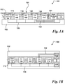
- Figs. 1A and 1B together illustrate an embodiment of a small scale (e.g., handheld) gas analysis device 100.
- Device 100 includes a substrate 102 on which are mounted a fluid handling assembly 101, a controller 126 coupled to the individual elements within fluid handling assembly 101, and a reading and analysis circuit 128 coupled to detector array 110 and to controller 126.
- the embodiment shown in the Figs. illustrates one possible arrangement of the elements on substrate 102, but in other embodiments the elements can, of course, be arranged on the substrate differently.
- Substrate 102 can be any kind of substrate that provides the required physical support and communication connections for the elements of device 100.
- substrate 102 can be a printed circuit board (PCB) of the single-layer variety with conductive traces on its surface, but in other embodiments it can be a PCB of the multi-layer variety with conductive traces in the interior of the circuit board.
- PCB printed circuit board
- substrate 102 can be chip or wafer made of silicon or some other semiconductor.
- substrate 102 can also be a chip or wafer in which optical waveguides can be formed to support optical communication between the components of device 100.
- Fluid handling assembly 101 includes a filter and valve assembly 104, a pre-concentrator 106, a gas chromatograph 108, a detector array 110 and a pump 112.
- Elements 104-112 are fluidly coupled in series: filter and valve assembly 104 is fluidly coupled to pre-concentrator 106 by fluid connection 116, pre-concentrator 106 is fluidly coupled to gas chromatograph 108 by fluid connection 118, gas chromatograph 108 is fluidly coupled to detector array 110 by fluid connection 120, and detector array 110 is coupled to pump 112 by fluid connection 122.
- elements 104-112 can be micro-electro-mechanical (MEMS) elements or MEMS-based elements, meaning that some parts of each device can be MEMS and other parts not. In other embodiments of device 100, some or all of elements 104-112 need not be MEMS or MEMS-based, but can instead be some non-MEMS chip scale device.
- MEMS micro-electro-mechanical
- Fluid handling assembly 101 also includes a shroud or cover 112 that protects individual elements 104-112.
- a fluid e.g., one or more gases
- Fluid handling assembly 101 also includes a shroud or cover 112 that protects individual elements 104-112.
- channels formed in shroud 112 provide the fluid connections between the elements, but in other embodiments the fluid connections between elements can be provided by other means, such as tubing. In still other embodiments shroud 112 can be omitted.
- Filter and valve assembly 104 includes an inlet 114 and an outlet coupled to fluid connection 116 such that fluid exiting filter and valve assembly 104 flows into pre-concentrator 106.
- Filter and valve assembly 104 includes a filter to remove particulates from fluid entering through inlet 114.
- the small scale of parts within the MEMS elements means that fluid entering through inlet 114 might need to be filtered to remove these particles so that the particles do not enter the MEMS elements and either them or render them inoperative.
- the filter portion of filter and valve assembly 104 can be omitted.
- Filter and valve assembly 104 also includes a valve so that further flow through inlet 114 into fluid handling assembly 101 can be stopped once sufficient fluid has passed through the device. Stopping further flow through inlet 114 prevents dilution of fluids that will flow out of pre-concentrator 106 during later operation of device 100 ( see description of operation below).
- filter and valve assembly 104 can also include a de-humidifier to remove water vapor from the fluid entering through inlet 114, thus improving the accuracy and sensitivity of device 100.
- Pre-concentrator 106 includes an inlet coupled to fluid connection 116 and an outlet coupled to fluid connection 118. Pre-concentrator 106 receives fluid from filter and valve assembly 104 through fluid connection 116 and outputs fluid to gas chromatograph 108 through fluid connection 118. As fluid flows through pre-concentrator 106, the pre-concentrator absorbs certain chemicals from the passing fluid, thus concentrating those chemicals for later separation and detection.
- pre-concentrator 106 can be a MEMS pre-concentrator, but in other embodiments pre-concentrator 106 can be a non-MEMS chip scale device. Further details of an embodiment of a MEMS pre-concentrator are described below in connection with Fig. 2 .
- Gas chromatograph 108 includes an inlet coupled to fluid connection 118 and an outlet coupled to fluid connection 120. Gas chromatograph 108 receives fluid from pre-concentrator 106 through fluid connection 118 and outputs fluid to detector array 110 through fluid connection 120. As fluid received from pre-concentrator 106 flows through gas chromatograph 108, individual chemicals in the fluid received from the pre-concentrator are separated from each other in the time domain for later input into detector array 110.
- gas chromatograph 108 can be a MEMS gas chromatograph, but in other embodiments gas chromatograph 108 can be a non-MEMS chip scale device. Further details of an embodiment of a MEMS gas chromatograph 108 are described below in connection with Figs. 3A-3C .
- gas chromatograph 108 can be any of the gas chromatographs shown in Fig. 10 et seq.
- gas chromatograph 108 includes multiple chromatographs, it can be necessary to adjust the number of downstream and/or upstream components in device 100 to coincide with the input or output configuration of the gas chromatograph.
- the chromatograph 1400 shown in Fig. 14A is used as chromatograph 108 in device 100, it can be necessary to adjust the number of detector arrays 110, pumps 112, and so forth, to correspond to the number of outputs of chromatograph 1400.
- Detector array 110 includes an inlet coupled to fluid connection 120 and an outlet coupled fluid connection 122. Detector array 110 receives fluid from gas chromatograph 108 through fluid connection 120 and outputs fluid to pump 112 through fluid connection 122. As fluid flows through detector array 110, the chemicals that were time-domain separated by gas chromatograph 108 enter the detector array and their presence and/or concentration is sensed by sensors within the detector array.
- detector array 110 can be a MEMS detector array, but in other embodiments detector array 110 can be a non-MEMS chip scale device. Further details of an embodiment of a detector array 110 are described below in connection with Fig. 4 . Although shown in the Fig. as a single detector array, in other embodiments detector array 110 can actually include multiple detector arrays.
- gas chromatograph 108 is a configuration made up of several individual chromatographs, such as chromatograph 1400 shown in Fig. 14 , it can be necessary to adjust the number of detector arrays to match the output configuration of the cascaded chromatographs.
- Pump 112 includes an inlet coupled to fluid connection 122, as well as an outlet coupled to an exhaust 124, such that pump 112 draws fluid from detector array 110 through fluid connections 122 and returns it to the atmosphere through exhaust 124.
- Pump 112 can be any kind of pump that meets the size and form factor requirements of device 100, provides the desired flow rate and flow rate control, and has adequate reliability (i.e., adequate mean time between failures (MTBF)).
- pump 112 can be a MEMS or MEMS-based pump, but in other embodiments it can be another type of pump. Examples of pumps that can be used include small axial pumps (e.g., fans), piston pumps, and electro-osmotic pumps. Although shown in the Fig.
- pump 112 can actually be made up of multiple pumps.
- gas chromatograph 108 is a cascaded configuration made up of several individual chromatographs, such as chromatograph 1400 shown in Fig. 14 , it can be necessary to adjust the number of pumps to match the output configuration of the cascaded chromatographs.
- Controller 126 is communicatively coupled to the individual elements within fluid handling assembly 101 such that it can send control signals and/or receive feedback signals from the individual elements.
- controller 126 can be an application-specific integrated circuit (ASIC) designed specifically for the task, for example a CMOS controller including processing, volatile and/or non-volatile storage, memory and communication circuits, as well as associated logic to control the various circuits and communicate externally to the elements of fluid handling assembly 101.
- ASIC application-specific integrated circuit
- controller 126 can instead be a general-purpose microprocessor in which the control functions are implemented in software.
- controller 126 is electrically coupled to the individual elements within fluid handling assembly 101 by conductive traces 130 on the surface or in the interior of substrate 102, but in other embodiments controller 126 can be coupled to the elements by other means, such as optical.
- Readout and analysis circuit 128 is coupled to an output of detector array 110 such that it can receive data signals from individual sensors within detector array 110 and process and analyze these data signals.
- readout and analysis circuit 128 can be an application-specific integrated circuit (ASIC) designed specifically for the task, such as a CMOS controller including processing, volatile and/or non-volatile storage, memory and communication circuits, as well as associated logic to control the various circuits and communicate externally.
- ASIC application-specific integrated circuit
- CMOS controller including processing, volatile and/or non-volatile storage, memory and communication circuits, as well as associated logic to control the various circuits and communicate externally.
- readout and analysis circuit 128 can instead be a general-purpose microprocessor in which the control functions are implemented in software.
- readout and analysis circuit 128 can also include signal conditioning and processing elements such as amplifiers, filters, analog-to-digital converters, etc., for both pre-processing of data signals received from detector array 110 and post-processing of data generated or extracted from the received data by readout and analysis circuit 128.
- signal conditioning and processing elements such as amplifiers, filters, analog-to-digital converters, etc.
- readout and analysis circuit 128 is electrically coupled to detector array 110 by conductive traces 132 positioned on the surface or in the interior of substrate 102, but in other embodiments controller 126 can be coupled to the elements by other means, such as optical means. Readout and analysis circuit 128 is also coupled to controller 126 and can send signals to, and receive signals from, controller 126 so that the two elements can coordinate and optimize operation of device 100. Although the illustrated embodiment shows controller 126 and readout and analysis circuit 128 as physically separate units, in other embodiments the controller and the readout and analysis circuit could be combined in a single unit.
- the system is first powered up and any necessary logic (i.e., software instructions) is loaded into controller 126 and readout and analysis circuit 128and initialized.
- the valve in filter and valve unit 104 is opened and pump 112 is set to allow flow through the fluid handling assembly. Fluid is then input to fluid handling assembly 101 through inlet 114 at a certain flow rate and/or for a certain amount of time; the amount of time needed will usually be determined by the time needed for pre-concentrator 106 to generate adequate concentrations of the particular analytes (e.g., chemicals or VOCs) whose presence and/or concentration are being determined.
- fluid As fluid is input to the system through inlet 114, it is filtered by filter and valve assembly 104 and flows through elements 104-112 within fluid handling assembly 101 by virtue of the fluid connections between these elements. After flowing through elements 104-112, the fluid exits the fluid handling assembly through exhaust 124.
- valve in filter and valve assembly 104 is closed to prevent further input of fluid.
- a heater in pre-concentrator 106 activates to heat the pre-concentrator. The heat releases the chemicals absorbed and concentrated by the pre-concentrator.
- pump 112 is activated to draw the released chemicals through gas chromatograph 108 and detector array 110 and output the chemicals through exhaust 124. Activation of pump 112 also prevents backflow through fluid handling assembly 101.
- gas chromatograph 108 As the chemicals released from pre-concentrator 106 are drawn by pump 112 through gas chromatograph 108, the chromatograph separates different chemicals from each other in the time domain-that is, different chemicals are output from the gas chromatograph at different times. As the different chemicals exit gas chromatograph 108 separated in time, each chemical enters MEMS detection array 110, where sensors in the detection array detect the presence and/or concentration of each chemical.
- the time-domain separation performed in gas chromatograph 108 substantially enhances the accuracy and sensitivity of MEMS detection array 110, since it prevents numerous chemicals from entering the detection array at the same time and thus prevents cross-contamination and potential interference in the sensors within the array.
- the detection array senses the interaction and outputs a signal to readout and analysis circuit 128, which can then use the signal to determine presence and/or concentration of the chemicals.
- readout and analysis circuit 128 can use various analysis techniques, such as correlation and pattern matching, to extract some meaning from the particular combination of chemicals present and their concentrations.
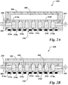
- Fig. 2A illustrates an embodiment of a MEMS pre-concentrator 200 that can be used as pre-concentrator 106 in device 100.
- Pre-concentrator 200 includes a substrate 202 having a cover plate 204 bonded thereto and sealed around the perimeter of the substrate to create a cavity 206.
- Substrate 202 has formed therein an inlet 208 on one side, an outlet 210 on a different side, and pockets 212 having absorbents therein.
- substrate 202 is a silicon substrate, but in other embodiments substrate 202 can of course be made of other materials.
- Heater 216 is formed on the side of substrate 202 opposite the side where cover plate 204 is attached.
- inlet 208, outlet 210 and pockets 212 can be formed using standard photolithographic patterning and etching. Although the illustrated embodiment shows seven pockets 212a-212g, the number of pockets needed depends on the number of different chemicals to be absorbed and concentrated, and on the nature of the absorbents used. In an embodiment where each absorbent absorbs only one chemical, the number of pockets 212 can correspond exactly to the number of chemicals to be absorbed and concentrated, but in other embodiments where each absorbent absorbs only one chemical a greater number of pockets can be used to increase the absorption area. In still other embodiments where each absorbent can absorb more than one chemical, a lesser number of pockets can be used.
- Each pocket 212 has a corresponding absorbent 214 in its interior-pocket 212a has absorbent 214a, pocket 212b has absorbent 214b, and so on.
- absorbents 214 can be coatings on the walls of pockets 212 or can be a continuous substance that partially or fully fills each pocket 212.
- Other embodiments can include combinations of granular, wall coatings or continuous filling absorbents.
- Each absorbent can have a chemical affinity for one or more particular chemicals, meaning that the exact absorbents used will depend on the number and nature of chemicals to be absorbed and concentrated. Examples of absorbents that can be used include cabopack B, cabopack X, etc.
- fluid from filter and valve assembly 104 enters through inlet 208, passes through absorbent 214a in pocket 212a, and enters cavity 206.
- Cover plate 204 helps guide fluid entering the cavity 206 into the different pockets 212b-212g and through absorbents 214b-214g, until the fluid, minus the chemicals absorbed by absorbents 214a-214g, exits the pre-concentrator through outlet 210.
- the valve in filter and valve assembly 104 is closed to prevent further flow through inlet 208. Heater 216 is then activated.
- Heater 216 heats absorbents 214a-214f, causing them to release the absorbed chemicals through processes such as outgassing. Simultaneously with activating heater 216, or shortly thereafter, pump 112 is activated, drawing the released chemicals out through outlet 210 to gas chromatograph 108.
- Fig. 2B illustrates an alternative embodiment of a MEMS pre-concentrator 250.
- MEMS pre-concentrator 250 is in many respects similar to MEMS pre-concentrator 200, The primary difference between the two is that in MEMS pre-concentrator 250, the cover plate 252 is directly bonded to the substrate 202 without formation of cavity 206 found in cover plate 204.
- channels/openings 252 can exist in substrate 202 between the different pockets 212 to allow the fluid to flow through adjacent pockets.
- fluid enters through inlet 208, passes through the different pockets 212a-212g via the channels/openings 252 between the pockets, and finally exits the pre-concentrator through outlet 210.
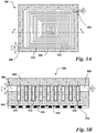
- MEMS gas chromatograph 300 includes a substrate 302 with an inlet 306 on one side, an outlet 308 on a different side, and a separation column 310 having a stationary phase coating on its walls.
- a cover plate 304 is bonded to substrate 302 to seal column 310.
- substrate 302 is a silicon substrate, but in other embodiments substrate 302 can of course be made of other materials.
- inlet 306, outlet 308 and column 310 can be formed using standard photolithographic patterning and etching, such as deep reactive ion etching (DRIE).
- DRIE deep reactive ion etching
- Temperature control 314 is formed on the side of substrate 302 opposite the side where cover plate 204 is attached.
- temperature control is integrated with chromatograph 300 and can include heating elements and/or cooling elements, or elements that are capable of both heating and cooling such as a Peltier device or thermo-electric cooler (TEC).
- TEC thermo-electric cooler
- Temperature control 314 can also include one or more temperature sensors 316 to allow for monitoring and/or feedback control of temperature control 314.
- Channel or column 310 provides a continuous fluid path from inlet 306 to outlet 308, and some or all of the walls of column 310 are coated with a stationary phase coating that can interact with the chemicals being separated by the chromatograph or, in other words, the column walls are coated with specific materials that have specific selectivity/separation power for the desired gas analysis.
- a stationary phase coating that can interact with the chemicals being separated by the chromatograph or, in other words, the column walls are coated with specific materials that have specific selectivity/separation power for the desired gas analysis.
- How thoroughly and how fast chemicals are separated from the fluid depend on the stationary phase coating, the overall path length of column 310, and the temperature. For a given stationary phase coating, the longer the column the better the chemical spectrum separation, but a long column also extends the separation time. For a given application, the required path length will therefore usually be determined by a tradeoff among the coating, the column length and the temperature.
- column 310 shows column 310 as a spiral column in which the column path length will depend on the number of coils in the spiral. In other embodiments, however, column 310 can be shaped differently. In one embodiment, column 310 can be between 1m and 10m in length, but in other embodiment can be outside this range. In the illustrated MEMS GC, column 310 can be formed by micromachining or micro-electro-mechanical-systems (MEMS) process on silicon wafer, glass wafer, PCB board, or any type of substrate.
- MEMS micro-electro-mechanical-systems
- fluid from pre-concentrator 106 enters through inlet 306 and passes through column 310.
- the different chemicals in the fluid interact with stationary phase coating 312 at different rates, meaning that the chemicals are separated after traveling through the column, with the chemicals that interact strongly with the stationary phase being separated first and the chemicals that interact weakly with the stationary phase being separated last.
- chemicals that interact strongly with the stationary phase are retained longer in the stationary phase, while chemicals that interacted weakly with the stationary phase retained less time in the stationary phase.
- this time-domain separation can occur according to molecular weight (e.g., chemicals with the lowest molecular weight are separated first, followed by higher molecular weights), but in other embodiments it can occur according to other chemical characteristics or other separation mechanisms.
- pump 112 draws them out of MEMS gas chromatograph 300 through outlet 308.
- the chemicals exit through outlet 308 in the reverse order of their separation-that is, chemicals with low retention time exit first, while chemicals with higher retention times exit later. After leaving outlet 308, the chemicals enter detector array 110.
- Fig. 3C illustrates an alternative embodiment of an individual gas chromatograph 350.
- Gas chromatograph 350 is in most respects similar to gas chromatograph 300 shown in Fig. 3B .
- the primary difference between gas chromatographs 300 and 350 is the configuration of the temperature control.
- temperature control 352 is not integrated into the chromatograph, but instead is an external component, such as a Peltier device, a thermo-electric cooler (TEC) or a heating and/or cooling plate, that is thermally coupled to the chromatograph.
- TEC thermo-electric cooler
- Thermal coupling between external temperature control 352 and the chromatograph can be accomplished, for example, using thermally conductive adhesives or with thermal interface materials.
- temperature control 352 can include one or more temperature sensors 354 to monitor the temperature and/or provide feedback control of the temperature control. Since the GC is small (about 1 inch range in one embodiment, but not limited to this range), fast heating and cooling control can be achieved with either the integrated or external temperature controls.
- FIGs. 3D and 3E together illustrate an alternative embodiment of an individual gas chromatograph 380.
- the primary difference between gas chromatographs 380 and 350 is the formation in chromatograph 380 of a conventional chromatography column instead of a MEMS chromatography column.
- Gas chromatograph 380 includes a substrate 382 having a cavity or opening 384 therein.
- a chromatography column 386 Positioned within cavity 384 is a chromatography column 386, which in one embodiment can be formed using coiled capillary tube used in conventional chromatography.
- the length of column 386 can be from 1-10m, but in other embodiments it can be necessary to limit the length to 1-3m because of the more bulky configuration.
- temperature control 390 is bonded to substrate 382 to close cavity 384, thus enclosing column 386.
- temperature control 390 can be an external temperature control as shown and described for Fig. 3C , and can include one or more temperature sensors 388 to monitor the temperature and/or provide feedback control of the temperature control.
- GC 380 can be packaged in a small size to achieve faster heating and cooling control.
- gas chromatograph 380 Operation of gas chromatograph 380 is similar to gas chromatograph 350 shown in Fig. 3C .
- the primary difference between gas chromatographs 380 and 350 is the formation of chromatography column.
- the column can be formed by coiled capillary tube used in conventional chromatography.
- the column is then enclosed by a temperature control 381 as shown in Fig. 3D .
- Such a GC can be packaged in a small size to achieve faster heating and cooling control.
- Figs. 4A-4B illustrate an embodiment of a detector array 400 that can be used as detector array 110 in device 100.
- Detector array 400 includes a substrate 402 with an array of sensors S1-S9 formed thereon.
- sensors S1-S9 form a regularly shaped 3-by-3 array of sensors, but in other embodiments the sensor array can have a greater or lesser number of sensors, and the sensors can be arranged in any pattern, regular or irregular.
- a cover 404 is bonded to the perimeter of substrate 402 to form a cavity 410 within which sensors S1-S9 are located.
- Cover 404 also includes an inlet 406 through which fluid can enter from gas chromatograph 108 and an outlet 408 through which fluid can exit to pump 112.
- a heater 412 is formed on the side of substrate 402 opposite the side where cover 404 is attached to control the temperature of detector array 400, and hence the sensors within the detector array, during operation.
- detector array 400 of course includes outputs by which signals generated by sensors S1-S9 can be output for processing.
- Each sensor S1-S9 includes a surface with a coating thereon.
- Each coating used will have an affinity for one or more of the particular chemicals being detected, such that the coating absorbs or chemically interacts with its corresponding chemical or chemicals.
- the interaction between coating and chemical changes a physical property of the sensor such as resonant frequency, capacitance or electrical resistance, and that changed physical property of the sensor can be measured using a transducer or other measurement device.
- the particular coatings chosen for sensors S1-S9 will depend on the chemicals that sensor array 110 will be used to detect.
- the chemical affinity of coatings also varies strongly with temperature, so that the operating temperature range should be considered in selecting coatings.
- sensor array 110 will be used to detect volatile organic compounds in human breath-such as benzene, toluene, n-octane, ethylbenzene, m,p-xylene, ⁇ -pinene, d-limonene, nonanal, and benzaldehyde, 2-methylhexane, 4-methyloctane, and so on-coatings that can be used in different applications include amorphous copolymers of 2,2-bistrifluoromethyl-4,5-difluoro-1,3-dioxole (PDD) and tetrafluoroethylene (TFE), PtCl2 (olefin), C8-MPN, etc.
- volatile organic compounds in human breath- such as benzene, toluene, n-octane, ethylbenzene, m,p-xylene, ⁇ -pinene, d-limonene, nonanal, and
- the illustrated embodiment has nine sensors, the number of sensors needed depends on the number of different chemicals to be detected, and on the nature of the coatings used on the sensors.
- the number of sensors can correspond exactly to the number of chemicals to be detected, but in other embodiments it can be desirable to have a given coating on more than one sensor for redundancy.
- there is no one-to-one correlation between chemicals to coatings in other words, each coating reacts with more than one different chemical and the reaction between different chemicals and a given coating will vary in nature and strength.
- a detector array having sensors with different coatings is therefore useful because the response of the detector array can have different patterns for different gases.
- sensors S1-S9 are MEMS sensors positioned on the surface of substrate 402, meaning that they are surface micromachined sensors. In other embodiments using MEMS sensors, however, sensors S1-S9 can be bulk micromachined sensors, meaning that at least some of the MEMS sensors are formed within substrate 402 instead of on the surface. Still other embodiments of sensor array 110 using MEMS sensors can include combinations of surface-micromachined and bulk-micromachined sensors. Different types of MEMS sensors can be used, depending on the application and the required sensitivity. Examples of MEMS sensors that can be used include chemiresistors, bulk acoustic wave (BAW)sensors, etc.
- BAW bulk acoustic wave
- one or more of sensors S1-S9 can be a non-MEMS sensor.
- non-MEMS sensors that can be used in detector array400 include quartz crystal microbalance (QCM) or surface acoustic wave (SAW) sensors with quartz or Gallium Arsenide (GaAs) substrates.
- QCM quartz crystal microbalance
- SAW surface acoustic wave
- GaAs Gallium Arsenide
- fluid from gas chromatograph 108 enters through inlet 406 and passes into cavity 410.
- Fluid entering cavity 410 carries time-domain separated chemicals. As each chemical enters cavity 410 it interacts with one or more sensors whose coating has an affinity for that chemical. The interaction of the chemical with the sensor is sensed and measured, and the presence and concentration of the particular chemical can be extracted. As more fluid flows into cavity 410, the first chemical is pushed out of cavity 410 through outlet 408 and fluid with the next time-domain-separated chemical enters cavity 410, interacts with the sensor array and is measured. This process continues until all the time-domain-separated chemicals from gas chromatograph 108 have flowed through detector array 110.
- detector array 110 can be re-usable: after all time-domain-separated chemicals have been sensed, heater 412 can be activated to heat the sensors and cause the coatings to release the respective chemicals with which they interacted, making the interaction reversible.
- heater 412 can be activated to heat the sensors and cause the coatings to release the respective chemicals with which they interacted, making the interaction reversible.
- heating of the sensor array could help release the partially absorbed gas from the coating materials.
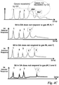
- Figure 4C illustrates an alternative embodiment of the operation of detector array 400 in device 100.
- analytes e.g., chemicals such as gases or volatile organic compounds (VOCs)
- VOCs volatile organic compounds
- the fluid flowing through system 100 contains seven analytes, but GC 108 could not completely separate all seven: analytes 1-3 were completely separated by GC108, as indicated by their narrow peaks on the graph, but analytes 4-5 could not be completely separated, nor could analytes 6-7, as indicated by their broad peaks in the graph.
- FIG. 4C illustrates the response of detector S4 where detector S4 has been chosen to be unresponsive to analytes 5-7, so that detector S4 can detect analyte 4 even though it wasn't completely separated by GC 108.
- the third graph in Fig. 4C illustrates the response of detector S5 where detector S5 has been chosen to be unresponsive to analytes 4 and 7, so that detector S5 can detect analytes 5 and 6 even though they did't completely separated by GC 108.
- the last graph in Fig. 4C illustrates the response of detector S6 where detector S6 has been chosen to be unresponsive to analytes 4, 5 and 6, so that detector S6 can detect analyte 7 even though it wasn't completely separated by GC 108.
- GC 108 and detector array effectively cooperate to separate chemicals that cannot be separated by GC108 alone.
- Fig. 5 illustrates an embodiment of a system 500 using an alternative embodiment of a MEMS-based gas analysis device 502.
- Device 502 is in most respects similar to device 100.
- the primary difference between device 502 and device 100 is the presence in device 502 of a wireless transceiver circuit 504 and an antenna 506 mounted on substrate 102.
- Wireless transceiver circuit 504 can both transmit (Tx) data and receive (Rx) data and is coupled to reading and analysis circuit 128 and antenna 506.
- transceiver 504 can be used to wirelessly transmit raw data from reading and analysis circuit 128 to one or both of a router 508 and a computer 510. When transmitted to router 508, the data can then be re-transmitted to another destination for analysis. For example, in an application where device 502 is used for health-related chemical analysis, data sent to router 508 can be re-transmitted to one or more of a doctor's office, a hospital, a government health department, or someplace else for analysis and interpretation.
- the doctor's office, hospital or health department can send instructions to device 502 through router 508, antenna 506 and transceiver 504 to signal the result, to try to fix or improve the data, or to signal that the test must be performed again.
- wireless transceiver 504 can be used to transmit raw data to computer 510.
- Computer 510 can either forward the raw data to a doctor, hospital, etc., as did the router, or can analyze the data with software installed thereon to provide extract information from the data, such as one or more possible medical diagnoses, and provide the extracted information to the user of device 502.
- computer 510 can also forward the diagnosis, alone or with the analysis and raw data, on to the doctor, hospital, etc.
- the doctor's office, hospital or health department can send instructions to device 502 through computer 510, antenna 506 and transceiver 504 to try to fix or improve the data, to signal that the test must be performed again, and so on.
- the raw data can be processed, and information such as potential diagnoses extracted from the data, by reading and analysis circuit 128.
- the potential diagnoses determined by reading and analysis circuit 128 can then be sent to computer 510 to be reviewed by the user and/or forwarded, or can be immediately forwarded alone or with the supporting raw data to the doctor's office, etc.
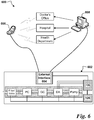
- Fig. 6 illustrates an embodiment of a system 600 using an alternative embodiment of a MEMS-based gas analysis device 602.
- Device 602 is in most respects similar to device 502.
- the primary difference between device 502 and device 602 is that the wireless transceiver circuit 504 and antenna 506 are replaced with a hardware data interface 604 coupled to reading and analysis circuit 128.
- hardware data interface 604 could be a network interface card, but in other embodiments hardware data interface can be an Ethernet card, a simple cable plug, etc.
- External devices can be connected to device 602 through traditional means such as cables. Although it has a different communication interface, device 602 and system 600 have all the same functionality as device 502 and system 500.
- MEMS-based gas analysis device 602 can transmit data to, and receive data from, one or both of a computer 608 and a wireless device 606, such as a cell phone or personal digital assistant (PDA).
- a wireless device 606 such as a cell phone or personal digital assistant (PDA).
- PDA personal digital assistant
- the data can then be forwarded to a doctor's office, hospital, or government health department, and the recipients of the data can in turn send data or instructions back to gas analysis device 602 through the wireless device.
- data when data is transmitted to computer 608 it can be forwarded or can be analyzed by the computer and the result displayed for the user and/or forwarded, and instructions can be transmitted to device 602 through computer 608.
- the data from gas analysis device 602 can be analyzed by reading and analysis circuit 128. After analysis by circuit 128, the extracted information (e.g., one or more diagnoses) and/or the raw data can be forwarded via the hardware data interface 604.
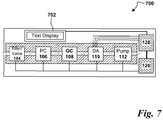
- Fig. 7 illustrates an alternative embodiment of a MEMS-based gas analysis device 700.
- Device 700 is in most respects similar to device 100.
- the primary difference between system 700 and device 100 is that device 700 includes an on-board display 702 for conveying to a user the results of the analysis performed by reading and analysis circuit 128.
- the illustrated embodiment uses an on-board text display 702, for example an LCD screen that can convey text information to a user.
- display 702 could be used to display the test results in analog numbers indicating the situation of patients.
- Display 702 could indicate a positive or negative diagnosis, could indicate probabilities of a given diagnosis, or could indicate the raw data from the detector array.
- simpler displays can be used, such as one with three lights that indicate a positive, negative, or indeterminate result depending on which light is switched on.
- Fig. 8 illustrates an alternative embodiment of a MEMS-based gas analysis device 800.
- Device 800 is in most respects similar to device 100.
- the primary difference between device 800 and device 100 is that in device 800 one or more elements of fluid handling assembly 101 are replaceable.
- the elements are made replaceable by mounting them onto substrate 102 using sockets: filter and valve assembly 104 is mounted to substrate 102 by socket 804, pre-concentrator is mounted to substrate 102 by socket 804, gas chromatograph 108 is mounted to substrate 102 by socket 808, detector array 110 is mounted to substrate 102 by socket 810, and pump 112 is mounted to substrate 102 by socket 812.
- sockets 804-812 are sockets such as zero insertion force (ZIF) sockets that permit easy replacement by a user, but in other embodiments other types of sockets can be used.
- ZIF zero insertion force
- the illustrated embodiment shows all the components of fluid handling assembly 101 being replaceable, in other embodiments only some of the components such as pump 112 and detector array 110 can be made replaceable.
- Fig. 9 illustrates an alternative embodiment of a MEMS-based gas analysis device 900.
- Gas analysis device 900 is in most respects similar to device 100.
- the primary difference between device 900 and device 100 is that device 900 includes provisions for an external pre-concentrator 902 (i.e., a pre-concentrator not mounted on substrate 102).
- a valve 904 is placed between pre-concentrator 106 and gas chromatograph 108, and provisions are made to attach external pre-concentrator 902 to the valve.
- Valve 904 allows the user to use external pre-concentrator 902 instead of, or in addition to, on-board pre-concentrator 106.
- external pre-concentrator 902 is a breath collection bag, but in other embodiments it can be something different.
- pre-concentrator 106 can be permanently removed and replaced by external pre-concentrator 902.
- external pre-concentrator 902 replaces pre-concentrator 106, instead of inserting a valve between pre-concentrator 106 and gas chromatograph 108, external pre-concentrator 902 can be coupled upstream of the filter and valve assembly 104.
- FIG. 9A illustrates a further alternative embodiment of a gas analysis device 950.
- Gas analysis device 950 is in most respects similar to device 100.
- the primary difference between device 950 and device 100 is that device 950 includes a three-way valve TV1 in the fluid connection between pre-concentrator 106 and gas chromatograph (GC) 108, as well as a fluid connection 952 that couples three-way valve TV1 to the fluid connection between detector array (DA) 110 and pump 112.
- GC gas chromatograph
- DA detector array
- Three-way valve TV1 and fluid connection 952 provide device 950 with different fluid paths for different operation modes.
- three-way valve TV1 When device 950 is operated in sampling mode (e.g., collecting a breath sample for analysis), three-way valve TV1 is set so that the fluid flows through device 950 along the flow path shown with the dotted line labeled S. In sampling mode, fluid enters device 950 and passes through filter/valve 104 and through pre-concentrator 106. Following the pre-concentrator, three-way valve TV1 diverts the flow into fluid connection 952 so that the flow bypasses GC 108 and DA 110 and goes into the inlet of pump 112, which then exhausts the fluid to the atmosphere.
- sampling mode fluid enters device 950 and passes through filter/valve 104 and through pre-concentrator 106.
- pre-concentrator 106 Following the pre-concentrator, three-way valve TV1 diverts the flow into fluid connection 952 so that the flow bypasses GC 108 and DA 110 and goes into the inlet of pump 112, which then exhausts the fluid to the atmosphere.
- three-way valve TV1 When device 950 is operated in analysis mode (e.g., when separating analytes such as VOCs), three-way valve TV1 is set so that the fluid flows through device 950 along the flow path shown with the dotted line labeled A. In analysis mode, fluid enters device 950 and passes through filter/valve 104 and through pre-concentrator 106. Following the pre-concentrator, three-way valve TV1 is set to direct the flow into GC 108 instead of fluid connection 952. After passing through GC 108, the flow continues into DA 110 for analysis and then goes into pump 112, after which it is exhausted to the atmosphere.
- Figure 9B illustrates a further alternative embodiment of a gas analysis device 975.
- Gas analysis device 975 is in most respects similar to device 100. The primary difference between device 975 and device 100 is that device 975 includes additional elements to provide different fluid paths for different operation modes.
- Device 975 includes a first three-way valve TV2 in the fluid connection between filter/valve unit 104 and pre-concentrator 106, as well as a second three-way valve TV3 in the fluid connection between PC 106 and gas chromatograph (GC) 108.
- a fluid connection 977 couples second three-way valve TV3 to a third three-way valve TV4, which is in turn coupled to the inlet of pump 112 by fluid connection 979.
- a fluid connection 983 couples first three-way valve TV2 to a fourth three-way valve TV5, and fourth three-way valve TV5 is in turn coupled to the outlet of pump 112 by fluid connection 981.
- three-way valves TV2-TV5 are set so that the fluid flows through device 975 along the flow path shown with the dotted line labeled S.
- sampling mode fluid enters device 975 and passes through filter/valve 104 and pre-concentrator 106.
- pre-concentrator 106 three-way valve TV3 diverts the flow into fluid connection 977, so that the flow bypasses GC 108 and DA 110 and goes to three-way valve TV4.
- Three-way valve TV4 is set so that it directs the flow to the inlet of pump 112, which then exhausts the fluid into fluid connection 981.
- Fluid connection 981 directs the fluid from pump 112 to three-way valve TV5, which is set to exhaust the fluid to the atmosphere.
- three-way valves TV2-TV5 are set so that the fluid flows through device 975 along the flow path shown with the dotted line labeled A.
- pump 112 draws fluid from the atmosphere into device 975 through three-way valve TV4 and fluid connection 979.
- Fluid connection 981 is coupled to the outlet of pump 112 and carries the fluid to three-way valve TV5, which is set to direct the fluid into fluid connection 983.
- Fluid connection 983 then carries the fluid to three-way valve TV2, which is set to direct the fluid to the inlet of PC 106.
- Three-way valve TV3 is set so that fluid exiting PC 106 is directed into GC 108,then into DA110, and then into the atmosphere.
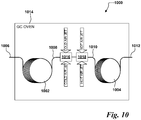
- FIG. 10 illustrates an example useful for understanding the invention of a cascaded gas chromatograph (CGC) 1000 using analyte focusing.
- CGC 1000 includes a first gas chromatograph (GC) 1002 having a fluid inlet 1006 and a fluid outlet 1008.
- a second GC 1004 has a fluid inlet 1010 and a fluid outlet 1012, with the fluid inlet 1010 coupled to the fluid outlet 1008 by a fluid connection.
- a cooling section 1016 and a heating section 1018 Surrounding the fluid connection between GC 1002 and GC 1004 are a cooling section 1016 and a heating section 1018. The entire assembly is positioned within a GC oven 1014.
- a carrier gas including one or more chemicals enters first GC 1002 through its fluid inlet 1006.
- the analytes circulates through GC 1002, they exit the GC through fluid outlet 1008 and flow in the fluid connection through cooling section 1016, where a cold air jet is directed into the cooling section to cool the analytes.
- the cold air used in cooling section 1016 can be produced using either liquid nitrogen or dry ice.
- the analytes continue into heating section 1018.
- heating section 1018 a hot air jet is used to heat the previously cooled analytes.
- the analytes proceed through fluid inlet 1010 to enter GC 1004 for further separation.
- CGC 1000 is bulky and expensive, and therefore cannot be used as portable gas analysis systems. Moreover, only a small section of CGC 1000 can be cooled due to its large thermal mass.
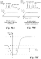
- Figs. 11A-11B illustrate an example useful for understanding the invention of focusing analytes (such as volatile organic compounds (VOCs)by cooling and/or heating a GC.
- the lower graph illustrates a temperature profile (e.g., a variation of temperature with time) that is applied to a GC
- the upper graph illustrates the response of a detector coupled to that GC.
- Fig. 11A illustrates an approach in which the GC begins at an initial temperature that is then ramped up to a target temperature at a desired ramping rate. With this temperature profile, gases 1, 2 and 3, are separated, but other gases remain unseparated by the GC. In most situations, the input analytes/VOCs have a broad concentration distribution when entering the GC column.
- FIG 11B illustrates an alternative approach.
- the temperature profile is shown in the bottom graph: the temperature of the chromatograph begins at initial temperature and is then cooled (reduced or lowered) to a lower temperature. After reaching the lowest temperature desired, the cooling is followed by heating the chromatograph to an operating temperature.
- the results of applying the temperature profile shown in the lower graph are shown in the detector response graph.
- the same gases 1-3 are separated from the analyte, but because of the focusing effect of cooling the analyte, gases that were previously un-separated are now separated, as shown by the sharp peaks in the detector response.
- the cooling produces an immediate focusing effect and narrowing (sharpening) of the spectrum profile.
- micro-GC is then heated to targeted temperature with the desired ramping rate to achieve analyte/VOC separation. Due to the operation of micro-GC cooling, the output spectrums are sharper compared to non-cooling operation. With sharper spectrums, gases/VOCs overlap at the micro-GC output will be reduced. As a result, more analytes can be resolved with micro-GC cooling.
- Fig. 11C illustrates an example useful for understanding the invention of a temperature profile that can be applied to a GC to obtain analyte focusing.
- the term "temperature profile" refers to a variation of temperature with time.
- the vertical axis represents a temperature of the GC, while the horizontal axis represents time.
- initial temperature T0 is substantially room temperature (typically around 20°C, but not limited to this temperature), but in other examples the initial temperature can be a temperature lower or higher than room temperature.
- the profile begins a first time period from time t 0 until time t 1 during which the temperature of the GC is lowered ( i.e., the GC is cooled) until it reaches a temperature T1 lower than the initial temperature T0.
- temperature T1 is a temperature below freezing, for example -10°C, but in other examples T1 can be any temperature lower than initial temperature T0.
- the duration of the first period ( t 1 -t 0 ) can be from 2-10 seconds, but in other examples the first period can be shorter or longer.
- the illustrated example shows the temperature decreasing linearly in the first period, in other examples the temperature decrease in the first period need not be linear.
- the temperature profile enters a second period from time t 1 to time t 2 during which the temperature of the GC is held substantially at or about T1.
- the temperature profile enters a third period from time t 2 to time t 3 during which the GC temperature is increased from T1 to a target temperature T2.
- T2 can be about +80°C, but in other examples other target temperatures are possible.
- the duration of the third period ( t 3 - t 2 ) can be from 2-10 seconds, but in other examples the third period can be shorter or longer.
- the illustrated example shows the temperature increasing linearly at the beginning of the third period and then increasing more slowly and non-linearly until the temperature reaches T2, but in other examples other distributions of temperature with time are possible.
- the temperature increase during the third period can be completely linear from t 2 to t 3 .
- the temperature of the gas chromatograph can initially overshoot temperature T2 and then be cooled to return the temperature to T2.
- Figs. 12A-12C illustrate the construction and operation of an example of a system 1200.
- System 1200 includes a GC 1202 having a fluid inlet 1204 and a fluid outlet 1206.
- a detector 1208 is coupled to the fluid outlet 1206 by a fluid connection.
- GC 1202 includes a temperature control that allows the GC to be heated, cooled, or both heated and cooled, for example by using a temperature profile such as the one illustrated in Fig. 11C .
- GC 1202 can have the construction illustrated in Fig. 3B-3C , but in other examples it can have a different construction, such as the one shown in Figs. 3D-3E or some other construction altogether.
- Detector 1208 can be any kind of chemical detector; in one example, it can be a detector array such as detector array 400 shown in Figs. 4A-4B , but in other examples other kinds of detector arrays can be used.
- the temperature control of gas chromatograph 1202 can be coupled to a control circuit (such as control circuit 126 when chromatograph 1202 is used in gas analysis systems such as the ones shown in Figures 1A-1B and 5-9 ) that applies the temperature profile to the temperature control.
- Figs. 12B-12C illustrates the results obtained with system 1200 when temperature profiles such as the one shown in Figs. 11A-11C are applied to GC 1200 and when a flame ionization detector (FID) is used ( Fig. 12B ) or when an acoustic resonator detector such as a surface acoustic wave (SAW) or QCM detector ( Fig. 12C ).
- FID flame ionization detector
- SAW surface acoustic wave
- QCM detector Fig. 12C
- Both figures show the results of applying three temperature profiles to GC 1202: a first temperature profile in which the temperature is kept at a constant 50C, a second temperature profile in which the temperature is reduced to 10°C, held for 15 seconds, and then increased to 50C, and a third temperature profile in which the temperature is reduced to -15C, held for 15 seconds, and then increased to 50C.
- the results obtained from both detectors show significant improvement in VOC (analyte) spectrum sharpening (narrower and higher peaks). The lower the cooling temperature that is applied, the better the sharpening of the spectrum. With an increase on the spectrum height, the detector's detection limit can be improved. Meanwhile, with a narrower VOC spectrum, additional VOCs can be resolved (separated) from neighboring VOCs.
- Figs. 13A-13C illustrate the construction and operation of a cascaded gas chromatograph (CGC) 1300.
- CGC 1300 can be used in place of, or one or more of its components can be used to supplement, gas chromatograph (GC) 108 and detector 110 in gas analysis systems such as the ones shown in Figures 1A-1B and 5-9 .
- CGC 1300 includes a first gas chromatograph (GC) 1302 coupled to a second GC 1304.
- GCs 1302 and 1304 are coupled in series such that outlet 1306 of GC 1302 is coupled to inlet 1310 of GC 1304 by a fluid connection 1314.
- Outlet 1312 of GC 1304 is coupled to a detector 1318 by a fluid connection 1316, although in other examples outlet 1312 could be coupled to some entirely different component.
- a fluid connection 1316 although in other examples outlet 1312 could be coupled to some entirely different component.
- the illustrated example has only two GCs, in other examples one or more additional GCs, as well as other components such as additional fluid connections, flow splitters, three-way valves detectors and switch valves, can be added to form a larger cascade of GCs.
- GCs 1302 and 1304 are MEMS GCs with individual temperature controls, such as those shown in Figures 3B or 3C , but in other examples they can be the capillary column GCs shown in Figs. 3D-3E or some other construction altogether.
- the individual temperature controls allow the operating temperature of each GC to be controlled independently of the other.
- GCs 1302 and 1304 need not be of the same type that is, CGC 1300 can include both MEMS and non-MEMS chromatographs.
- both chromatographs can have the same kind of temperature control, but in other examples both chromatographs need not have the same temperature control; for example, in the illustrated example with two MEMS chromatographs, GC 1302 can have an integrated temperature control as shown in Fig. 3B , while GC 1304 has an external temperature control, as shown in Figs. 3C-3E .
- detector 1318 is a detector array as shown in Figs. 4A-4B , but in other examples it can be a different type of detector.
- the temperature control of GCs 1302 and 1304 can be coupled to a control circuit (such as control circuit 126 when CGC 1300 is used in gas analysis systems such as the ones shown in Figures 1A-1B and 5-9 ) that applies a temperature profile to the temperature control. Because the temperature controls of GCs 1302 and 1304 are independent, in some examples different temperature profiles can be applied to each GC.
- a control circuit such as control circuit 126 when CGC 1300 is used in gas analysis systems such as the ones shown in Figures 1A-1B and 5-9 .
- GCs 1302 and 1304 can have the same characteristics, but in other examples GCs 1302 and 1304 need not have the same characteristics and can have different column lengths, column coatings, operating temperatures, etc.
- GC 1302 can be coated with material A, which can be especially selective to polar or non-polar chemicals, and can have its optimum temperature control profile to separate specific chemicals.
- GC 1304 can have a different column length and can be coated with another material B, which can separate different chemicals that GC 1302 cannot resolve (separate); in other words, GC 1304 is complementary to GC 1302. Since each GC in the configuration can has its own temperature control, GC 1304 can be optimized to separate the remaining gases of interest that are not resolved (separated) by GC 1302. The separated gases can then be detected by detector 1318 at output of GC 1304.
- a carrier fluid having one or more chemicals therein enters GC 1302 through inlet 1306 and flows through the GC's column while a temperature profile from Figs. 11C or 13B is applied to the GC's temperature control.
- the carrier fluid with any chemicals not resolved (separated) by GC 1302, exits through outlet 1308 into fluid connection 1314.
- Fluid connection 1314 carries the fluid into GC 1304, where the fluid flows through the GC's column while a temperature profile from Figs. 11C or 13C , which can be the same or different than the profile applied to GC 1302, is applied to the temperature control of GC 1304.
- Outlet 1312 of GC 1304 is coupled to a detector 1318, which can then be used to detect the chemicals separated from the carrier fluid by the two GCs.
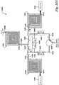
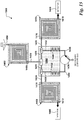
- Figs. 14A-14B together illustrate the construction and operation of an embodiment of a multi-dimensional gas chromatograph 1400.
- Embodiments of gas chromatograph 1400 can be used in place of, or one or more of its components can be used to supplement, gas chromatograph (GC) 108 and/or detector 110 in gas analysis systems such as the ones shown in Figs. 1A-1B and 5-9 .
- GC gas chromatograph
- Multi-dimensional gas chromatograph 1400 includes a first gas chromatograph (GC) 1402, a second GC 1408 and a third GC 1414 fluidly coupled to each other by several components that together form a "Dean switch.”
- GC gas chromatograph
- Each of the first, second and third GCs has its own temperature control that is independent of the others.
- the first, second and third GCs can have the construction illustrated in Figs. 3A-3C , but in other embodiments they can have a different construction, such as the one shown in Figs. 3D-3E or some other construction altogether.
- the first, second and third gas chromatographs need not have the same construction.
- GCs 1402, 1408 and 1414 can have the same characteristics, but in other embodiments the individual GCs need not have the same characteristics and can have different column lengths, column coatings, operating temperatures, etc.
- the temperature controls of GCs 1402, 1408 and 1414 can be coupled to a controller or control circuit (such as control circuit 126 when multi-dimensional chromatograph 1400 is used in gas analysis systems such as the ones shown in Figures 1A-1B and 5-9 ) that applies temperature profiles to the temperature controls of the individual GCs during operation.
- First GC 1402 includes a fluid inlet 1404 through which the analytes (e.g., volatile organic compounds (VOCs)) enter the GC and a fluid outlet 1406 through which separated chemicals exit GC 1402.
- Fluid outlet 1406 is coupled by fluid connection 1420 to a first Y-splitter Y1.
- First Y splitter Y1 is coupled to second Y-splitter Y2 by fluid connection 1422 and to third Y-splitter Y3 by fluid connection 1426.
- Second Y-splitter Y2 is further fluidly coupled to fluid inlet 1410 of second GC 1408 by fluid connection 1424, and fluid outlet 1412 of GC 1408 is coupled to a detector 1446.
- third Y-splitter Y3 is coupled to fluid inlet 1416 of GC 1414 by fluid connection 1428, and fluid outlet 1418 of GC 1414 is coupled to a detector 1448.
- Second Y-splitter Y2 is coupled by secondary fluid connection 1430 to flow rate restrictor1432, and flow-rate restrictor1432 is coupled by fluid connection 1434 to a three-way valve 1436.
- third Y-splitter Y3 is coupled by secondary fluid connection 1442 to flow rate restrictor 1440, and flow-rate restrictor 1440 is coupled by fluid connection 1433 to three-way valve 1436.
- Three-way valve 1436 is also coupled to a source of a secondary carrier gas.
- a flow resistor 1444 can optionally be fluidly coupled between fluid connections 1430 and 1442.
- the group of elements including the Y-splitters, the flow rate restrictors, the flow resistor, and the fluid connections among them together form a "Dean switch.”
- Use of the Dean switch permits the use of "heart-cutting.”
- one or more unresolved (i.e., un-separated) analytes from a first chromatograph (first dimension) are transferred to one or more additional chromatographs having a different polarity (second dimension) where the separation of the compounds un-separated by the first chromatograph will be achieved.
- the carrier gas containing chemicals is directed into fluid inlet 1404 of GC 1404. Separated and unseparated analytes exit through fluid connection 1420 to Y-splitter Y1.
- three-way valve 1436 is set to direct a secondary carrier gas into fluid connection 1438, so that the secondary carrier gas will flow through flow rate restrictor 1440 to Y-splitter Y3, where a portion of the secondary gas will flow into third GC 1414 and the remaining portion will flow through Y-splitters Y1 and Y2 into second GC 1408.
- flow resistor 1444 is present, part of the secondary gas flows though the flow resistor.
- FIG. 14B illustrates another mode of operation of multi-dimensional GC 1400 in which flow is directed into third GC 1414 instead of second GC 1408 by switching three-way valve 1436 to its other position, such that the flow path S of the secondary carrier gas now changes the primary path P.
- temperature profiles are applied to the individual GCs to improve separation of the analytes. Because the temperature controls of GCs are independent, in some embodiments different temperature profiles can be applied to each GC.
- FIG 15 illustrates an alternative embodiment of a multi-dimensional gas chromatograph 1500.
- Embodiments of gas chromatograph 1500 can be used in place of, or one or more of its components can be used to supplement, gas chromatograph (GC) 108 and/or detector 110 in gas analysis systems such as the ones shown in Figs. 1A-1B and 5-9 .
- Multi-dimensional chromatograph 1500 is in most respects similar to multi-dimensional chromatograph 1400.
- the primary difference between chromatographs 1400 and 1500 is that in chromatograph 1500 elements of the Dean switch are formed on a microchip 1502.
- Y-splitters Y1, Y2 and Y3 are formed on chip 1502 along with flow rate restrictors 1432 and 1440 and fluid connections between these elements.
- additional elements such as flow resistor 1444 can also be formed on chip 1502.
- FIG 16 illustrates another alternative embodiment of a multi-dimensional gas chromatograph 1600.
- Embodiments of gas chromatograph 1600 can be used in place of, or one or more of its components can be used to supplement, gas chromatograph (GC) 108 and/or detector 110 in gas analysis systems such as the ones shown in Figs. 1A-1B and 5-9 .
- Multi-dimensional chromatograph 1600 is in most respects similar to multi-dimensional chromatographs 1400 and 1500.
- the individual GCs 1602, 1604 and 1606 in chromatograph 1600 have at least the same features and characteristics as the individual GCs in chromatographs 1400 and 1500.
- chromatograph 1600 The primary difference between chromatograph 1600 and chromatographs 1400 and 1500 is that in chromatograph 1600 certain elements of the Dean switch are integrally formed in the individual GCs.
- Y-splitters Y1 is integrally formed in first GC 1602, along with fluid connections that allow GC 1602 to be coupled to the other GCs.
- second GC 1604 has flow rate restrictor 1432 and Y-splitter Y2 formed therein
- third GC 1606 has third Y-splitter Y3 and flow rate restrictor 1440 formed therein.
- Embodiments are disclosed of a new method of gas analyte (e.g., chemicals such as volatile organic compounds (VOCs)) spectrum sharpening and separation enhancement using multi-dimensional miniaturized gas chromatography column (GC) or micro-GC configuration.
- gas analyte e.g., chemicals such as volatile organic compounds (VOCs)
- VOCs volatile organic compounds
- the disclosed embodiments utilizes miniaturized GC / micro-GC columns, which can be cascaded with different coating materials for gas separation analysis.
- the micro-GCs are small in size (can be fabricated into micro-chip size if necessary) and thus can be promptly cooled down to sub-zero temperature with a simple small cooling device (e.g., thermoelectric cooler, TE cooler), which cannot be achieved using traditional bulky GC unless liquid nitrogen is used.
- a simple small cooling device e.g., thermoelectric cooler, TE cooler
- the disclosed embodiments can also include a cascade of multiple micro-GCs to form a heart-cutting gas chromatography configuration.
- the disclosed embodiments are the first implementation of a direct fast GC cooling on micro-GC with simple cooling device, which allows the possibility of achieving spectrum sharpening without using liquid nitrogen. Meanwhile, they also improve the detection limit. As a result, the disclosed embodiments can be implemented as a portable gas analysis system and significantly improve the system resolution and detection limit.
Landscapes
- Chemical & Material Sciences (AREA)
- Physics & Mathematics (AREA)
- Analytical Chemistry (AREA)
- Health & Medical Sciences (AREA)
- Life Sciences & Earth Sciences (AREA)
- Biochemistry (AREA)
- General Health & Medical Sciences (AREA)
- General Physics & Mathematics (AREA)
- Immunology (AREA)
- Pathology (AREA)
- Engineering & Computer Science (AREA)
- Mechanical Engineering (AREA)
- Nanotechnology (AREA)
- Acoustics & Sound (AREA)
- Sampling And Sample Adjustment (AREA)
Claims (11)
- Vorrichtung, die Folgendes enthält:einen ersten Gaschromatographen (108; 1402), der einen Fluideinlass (1404), einen Fluidauslass (1406) und eine erste Temperatursteuerung (314) enthält; undeine Steuereinheit (126), die an die erste Temperatursteuerung (314) gekoppelt ist, wobei die Steuereinheit (126) eine Logik enthält, um ein erstes Temperaturprofil auf die erste Temperatursteuerung (314) anzuwenden, um den ersten Gaschromatographen (108; 1402) zu erwärmen, zu kühlen oder sowohl zu erwärmen als auch zu kühlen,einen zweiten Gaschromatographen (1408), der einen Fluideinlass (1410), einen Fluidauslass (1412) und eine zweite Temperatursteuerung enthält; undeinen dritten Gaschromatographen (1414), der einen Fluideinlass (1416), einen Fluidauslass (1418) und eine dritte Temperatursteuereinheit enthält; wobeider Fluidauslass (1406) des ersten Gaschromatographen (108; 1402) durch ein Herzschneidventil an die Fluideinlässe (1410, 1416) des zweiten und des dritten Gaschromatographen (1408, 1414) gekoppelt ist, die zweite und die dritte Tempertatursteuerung an die Steuereinheit (126) gekoppelt sind und die Steuereinheit (126) eine Logik enthält, um ein zweites Temperaturprofil auf die zweite Temperatursteuerung und ein drittes Temperaturprofil auf die dritte Temperatursteuerung anzuwenden, um den zweiten und den dritten Gaschromatographen (1408, 1414) zu erwärmen, zu kühlen oder sowohl zu erwärmen als auch zu kühlen, wobeidas Herzschneidventil Folgendes enthält:einen ersten Y-Verteiler, der an den Fluidauslass (1406) des ersten Gaschromatographen (108; 1402) gekoppelt ist;einen zweiten Y-Verteiler, der an den ersten Y-Verteiler, den Fluideinlass (1410) des zweiten Gaschromatographen (1408) und eine erste sekundäre Fluidverbindung (1430, 1434) gekoppelt ist; undeinen dritten Y-Verteiler, der an den ersten Y-Verteiler, den Fluideinlass (1416) des dritten Gaschromatographen (1414) und eine zweite sekundäre Fluidverbindung (1442, 1438) gekoppelt ist, unddas Herzschneidventil ferner einen Strömungswiderstand (1444), der zwischen einem ersten Durchflussregulierer (1432) und dem zweiten Y-Verteiler an die erste sekundäre Fluidverbindung (1430, 1434) gekoppelt ist, und der zwischen einem zweiten Durchflussregulierer (1440) und dem Y-Verteiler an die zweite sekundäre Fluidverbindung gekoppelt ist, enthält.
- Vorrichtung nach Anspruch 1, wobei das Herzschneidventil an einem Mikrochip (1502) gebildet ist.
- Gasanalysesystem, das Folgendes enthält:eine Vorrichtung nach Anspruch 1;ein Substrat (102),wobei das System ferner Folgendes enthält:eine erste Erkennungseinrichtung (1446) und eine zweite Erkennungseinrichtung (1448), wobei die Erkennungseinrichtungen (1446, 1448) einen ersten Fluideinlass besitzen, wobei der Fluideinlass von jeder der Erkennungseinrichtungen fluidtechnisch an den Fluidauslass (1412) des zweiten Gaschromatographen (1408) bzw. den Fluidauslass (1418) des dritten Gaschromatographen (1414) gekoppelt ist;die Steuereinheit (126) an die Gaschromatographen (108; 1402, 1408, 1414) und an die Erkennungseinrichtungen (1446, 1448) gekoppelt ist, wobei die Steuereinheit (126) mit den Gaschromatographen (108; 1402, 1408, 1414) und mit den Erkennungseinrichtungen (1446, 1448) kommunizieren kann; undeine Ausleseschaltung, die an die Erkennungseinrichtungen (1446, 1448) und an die Steuereinheit (126) gekoppelt ist, wobei die Ausleseschaltung mit der Steuereinheit (126) und den Erkennungseinrichtungen (1446, 1448) kommunizieren kann.
- Vorrichtung nach Anspruch 1, wobei das erste Temperaturprofil vom zweiten Temperaturprofil verschieden ist.
- Vorgang zum Abscheiden im Zeitbereich einer oder mehrerer Chemikalien von einem Fluid, wobei der Vorgang Folgendes umfasst:Einspritzen eines Fluids, das mehrere Chemikalien enthält, in den ersten Gaschromatographen (108; 1402) von einem Gasanalysesystem nach Anspruch 3;Anwenden des ersten Temperaturprofils auf die erste Temperatursteuerung, um den ersten Gaschromatographen (108; 1402) zu erwärmen, zu kühlen oder sowohl zu erwärmen als auch zu kühlen;Detektieren jeder der mehreren im Zeitbereich abgeschiedenen Chemikalien unter Verwendung eines oder mehrerer Sensoren in der ersten und der zweiten Erkennungseinrichtung (1446, 1448), die an den zweiten Gaschromatographen (1408) bzw. den dritten Gaschromatographen (1414) gekoppelt sind; undVerarbeiten von Signalen des einen oder der mehreren Sensoren in der ersten und der zweiten Erkennungseinrichtung (1446, 1448), um die Anwesenheit und Konzentration jeder Chemikalie zu bestimmen.
- Vorgang nach Anspruch 5, der ferner Folgendes umfasst:Einspritzen von Fluid vom Fluidauslass (1406) des ersten Gaschromatographen (108; 1402) in einen Fluideinlass (1410) des zweiten Gaschromatographen (1408), der die zweite Temperatursteuerung besitzt;Anwenden des zweiten Temperaturprofils auf die zweite Temperatursteuerung, um den zweiten Gaschromatographen (1408) zu erwärmen, zu kühlen oder sowohl zu erwärmen als auch zu kühlen.
- Vorgang nach Anspruch 5, der ferner Folgendes umfasst:Einspritzen von Fluid vom Fluidauslass (1406) des ersten Gaschromatographen (108; 1402) in einen Fluideinlass (1410) des zweiten Gaschromatogra= phen (1408), der die zweite Temperatursteuerung besitzt;Einspritzen von Fluid vom Fluidauslass (1406) des ersten Gaschromatographen (108; 1402) in einen Fluideinlass (1416) des dritten Gaschromatographen (1414), der die dritte Temperatursteuerung besitzt;Anwenden des zweiten Temperaturprofils auf die zweite Temperatursteuerung, um den zweiten Gaschromatographen (1408) zu erwärmen, zu kühlen oder sowohl zu erwärmen als auch zu kühlen; undAnwenden des dritten Temperaturprofils auf die dritte Temperatursteuerung, um den dritten Gaschromatographen (1414) zu erwärmen, zu kühlen oder sowohl zu erwärmen als auch zu kühlen.
- Vorgang nach Anspruch 5, der ferner vor dem Abscheiden im Zeitbereich das Vorkonzentrieren der mehreren Chemikalien in einem Vorkonzentrator umfasst.
- Vorgang nach Anspruch 8, der ferner vor dem Vorkonzentrieren der Chemikalien ein Filtern des Fluids umfasst.
- Vorgang nach Anspruch 5, wobei das Verarbeiten der Signale ferner das Analysieren der Anwesenheit und Konzentration jeder Chemikalie umfasst, um eine Bedeutung zu bestimmen.
- Vorgang nach Anspruch 5, wobei das Detektieren jeder der mehreren im Zeitbereich abgeschiedenen Chemikalien ferner das Detektieren einer oder mehrerer nicht abgeschiedener oder teilweise abgeschiedener Chemikalien unter Verwendung eines Sensors, der für die nicht abgeschiedenen oder teilweise abgeschiedenen Chemikalien selektiv ist, umfasst.
Applications Claiming Priority (3)
| Application Number | Priority Date | Filing Date | Title |
|---|---|---|---|
| US32739210P | 2010-04-23 | 2010-04-23 | |
| US13/089,850 US8978444B2 (en) | 2010-04-23 | 2011-04-19 | Gas analyte spectrum sharpening and separation with multi-dimensional micro-GC for gas chromatography analysis |
| PCT/US2011/033325 WO2011133721A2 (en) | 2010-04-23 | 2011-04-20 | Gas analyte spectrum sharpening and separation with multi-dimensional micro-gc for gas chromatography analysis |
Publications (3)
| Publication Number | Publication Date |
|---|---|
| EP2561344A2 EP2561344A2 (de) | 2013-02-27 |
| EP2561344A4 EP2561344A4 (de) | 2015-07-22 |
| EP2561344B1 true EP2561344B1 (de) | 2018-11-14 |
Family
ID=44814630
Family Applications (1)
| Application Number | Title | Priority Date | Filing Date |
|---|---|---|---|
| EP11772674.5A Active EP2561344B1 (de) | 2010-04-23 | 2011-04-20 | Gasanalyt-spektrumsschärfung und -trennung mit mehrdimensionalem mikro-gc zur gaschromatographie-analyse |
Country Status (5)
| Country | Link |
|---|---|
| US (5) | US8978444B2 (de) |
| EP (1) | EP2561344B1 (de) |
| CN (2) | CN106324160B (de) |
| TW (1) | TWI547689B (de) |
| WO (1) | WO2011133721A2 (de) |
Families Citing this family (31)
| Publication number | Priority date | Publication date | Assignee | Title |
|---|---|---|---|---|
| US8087283B2 (en) | 2008-06-17 | 2012-01-03 | Tricorntech Corporation | Handheld gas analysis systems for point-of-care medical applications |
| EP2369989A4 (de) | 2008-12-01 | 2013-05-15 | Tricorntech Corp | Atemanalysesystem und -vefahren für die diagnose und behandlung von asthma, tuberkulose und lungenkrebs |
| US8999245B2 (en) * | 2009-07-07 | 2015-04-07 | Tricorn Tech Corporation | Cascaded gas chromatographs (CGCs) with individual temperature control and gas analysis systems using same |
| US8707760B2 (en) | 2009-07-31 | 2014-04-29 | Tricorntech Corporation | Gas collection and analysis system with front-end and back-end pre-concentrators and moisture removal |
| US8978444B2 (en) | 2010-04-23 | 2015-03-17 | Tricorn Tech Corporation | Gas analyte spectrum sharpening and separation with multi-dimensional micro-GC for gas chromatography analysis |
| FR2993990B1 (fr) | 2012-07-26 | 2015-04-03 | Commissariat Energie Atomique | Micro-dispositif d'analyse par chromatographie en phase gazeuse offrant une grande compacite |
| US10859474B2 (en) | 2013-02-28 | 2020-12-08 | TricornTech Taiwan | Real-time on-site gas analysis network for ambient air monitoring and active control and response |
| US10197519B2 (en) * | 2013-03-15 | 2019-02-05 | H2Scan Corporation | Gas sensing systems and methods |
| JP6256933B2 (ja) * | 2013-05-23 | 2018-01-10 | 木村 光照 | 濃縮機能を有する水素ガスセンサとこれに用いる水素ガスセンサプローブ |
| WO2015084776A1 (en) * | 2013-12-02 | 2015-06-11 | Geoservices Equipements Sas | Fast field mud gas analyzer |
| US9733225B2 (en) * | 2015-03-07 | 2017-08-15 | Matthew David Armstrong | Spectroscopic breath detector |
| TWI585405B (zh) * | 2015-04-30 | 2017-06-01 | 名閎科技股份有限公司 | 揮發性有機物質量測系統 |
| US10520490B2 (en) * | 2015-08-06 | 2019-12-31 | Htc Corporation | Gas detecting device and gas detecting method using the same |
| DE102015219838A1 (de) * | 2015-10-13 | 2017-04-13 | bentekk GmbH | Kontinuierliche und trennende Gasanalyse |
| US10371674B2 (en) * | 2016-04-13 | 2019-08-06 | Horiba Stec, Co., Ltd. | Chromatograph sampler and method for operating chromatograph sampler |
| JP6810649B2 (ja) * | 2016-05-17 | 2021-01-06 | 株式会社堀場製作所 | ガス分析装置 |
| US11016066B2 (en) * | 2016-06-17 | 2021-05-25 | Koninklijke Philips N.V. | Compact gas analysis device and method |
| CN106940353A (zh) * | 2017-04-28 | 2017-07-11 | 中国科学院电子学研究所 | 多传感色谱检测仪及其检测方法 |
| US11927574B2 (en) | 2017-05-15 | 2024-03-12 | The Regents Of The University Of Michigan | Progressive cellular architecture for microfabricated gas chromatograph |
| US10866220B2 (en) * | 2017-05-15 | 2020-12-15 | The Regents Of The University Of Michigan | Progressive cellular architecture for microfabricated gas chromatograph |
| US20190033275A1 (en) * | 2017-07-25 | 2019-01-31 | Pulmostics Limited | Temperature variation for sensor array based detection technology |
| US11331019B2 (en) | 2017-08-07 | 2022-05-17 | The Research Foundation For The State University Of New York | Nanoparticle sensor having a nanofibrous membrane scaffold |
| CN108490092A (zh) * | 2018-03-27 | 2018-09-04 | 天津大学 | 一种气体检测系统 |
| US11592427B2 (en) | 2018-10-01 | 2023-02-28 | Brown University | Multi-parametric machine olfaction |
| US11668677B2 (en) * | 2019-04-23 | 2023-06-06 | Pall Corporation | Aircraft air contaminant analyzer and method of use |
| US11559246B2 (en) * | 2019-05-15 | 2023-01-24 | Know Biological, Inc. | Health monitoring device |
| US11020042B2 (en) * | 2019-05-15 | 2021-06-01 | Know Biological, Inc. | Seizure detection device |
| WO2023039473A1 (en) * | 2021-09-08 | 2023-03-16 | Georgia Tech Research Corporation | Vapor analyzers and vapor analysis systems and methods |
| US12352732B1 (en) * | 2022-06-21 | 2025-07-08 | National Technology & Engineering Solutions Of Sandia, Llc | Monolithic multi-dimensional chromatography |
| JP2025521536A (ja) * | 2022-06-22 | 2025-07-10 | ザ レジェンツ オブ ザ ユニバーシティ オブ ミシガン | 多次元ガス・クロマトグラフィ・システム用の流量制限空気式モジュレータ |
| FR3157547B1 (fr) * | 2023-12-22 | 2026-03-20 | Centre Nat Etd Spatiales | Système de chromatographie |
Family Cites Families (120)
| Publication number | Priority date | Publication date | Assignee | Title |
|---|---|---|---|---|
| DE1079352B (de) | 1958-03-04 | 1960-04-07 | Perkin Elmer Corp | Geraet zur Trennung von Stoffgemischen durch Gaschromatographie |
| US3112639A (en) | 1960-01-04 | 1963-12-03 | Beckman Instruments Inc | Dual column gas chromatograph and method for analysis |
| US3538744A (en) | 1967-11-09 | 1970-11-10 | Phillips Petroleum Co | Chromatography apparatus |
| US4470298A (en) | 1978-01-30 | 1984-09-11 | Gomidas Jibelian | Method and apparatus for analyzing gases |
| US4670405A (en) | 1984-03-02 | 1987-06-02 | The United States Of America As Represented By The United States Department Of Energy | Sensor array for toxic gas detection |
| US4888295A (en) | 1984-03-02 | 1989-12-19 | The United States Of America As Represented By The United States Department Of Energy | Portable system and method combining chromatography and array of electrochemical sensors |
| US5106756A (en) * | 1984-03-02 | 1992-04-21 | The United States Of America As Represented By The United States Department Of Energy | Method and system for gathering a library of response patterns for sensor arrays |
| JPS60230058A (ja) | 1984-04-27 | 1985-11-15 | Sord Comput Corp | ポータブルキャピラリーガスクロマトグラフ装置用シリコンウエハ |
| US4869876A (en) | 1984-04-30 | 1989-09-26 | International Business Machines Corp. | Multi-purpose plural-oven gas chromatography system with shared controls |
| DE3708504A1 (de) | 1987-03-16 | 1988-09-29 | Siemens Ag | Einrichtung zur stroemungsteilung bei der gaschromatographischen analyse |
| US5099743A (en) | 1987-07-08 | 1992-03-31 | Thermedics Inc. | Selective detection with high speed gas chromatography |
| US4948389A (en) * | 1989-05-22 | 1990-08-14 | Hewlett-Packard Company | Gas chromatograph having cyro blast coolings |
| US5109691A (en) | 1989-12-08 | 1992-05-05 | Research Corporation Technologies, Inc. | Explosive detection screening system |
| FR2652417B1 (fr) * | 1989-09-22 | 1993-12-03 | Air Liquide | Procede et dispositif de dosage d'impuretes dans un gaz par chromatographie en phase gazeuse et utilisation pour la calibration d'impuretes dopantes dans le silane. |
| US5108705A (en) | 1990-03-12 | 1992-04-28 | Thermedics Inc. | Vapor detection with high speed gas chromatography |
| US5071547A (en) | 1990-03-23 | 1991-12-10 | Separations Technology, Inc. | Column chromatographic column apparatus with switching capability |
| SE470347B (sv) | 1990-05-10 | 1994-01-31 | Pharmacia Lkb Biotech | Mikrostruktur för vätskeflödessystem och förfarande för tillverkning av ett sådant system |
| US5268302A (en) * | 1990-05-29 | 1993-12-07 | Thermedics Inc. | Selective, high speed detection of vapors with analysis of multiple GC-separated portions |
| US5281256A (en) * | 1990-09-28 | 1994-01-25 | Regents Of The University Of Michigan | Gas chromatography system with column bifurcation and tunable selectivity |
| US5108468A (en) | 1991-03-26 | 1992-04-28 | General Electric Company | Switching system for a multidimensional gas chromatograph |
| JPH05126817A (ja) * | 1991-10-31 | 1993-05-21 | Shimadzu Corp | ガスクロマトグラフ |
| CA2097363A1 (en) | 1992-06-03 | 1993-12-04 | Hideo Ueda | Expired air examination device and method for clinical purpose |
| CA2098215A1 (en) | 1992-06-12 | 1993-12-13 | Hideo Ueda | Expired gas analytical method and device |
| US5770088A (en) | 1992-06-30 | 1998-06-23 | Daicel Chemical Industries, Ltd. | Simulated moving bed chromatographic separation process |
| JPH06242095A (ja) | 1993-01-29 | 1994-09-02 | Zenkoku Sekiyu Kyokai | ガソリン中の灯油、メタノール、btx及びmtbeの同時定量分析方法 |
| US5471055A (en) | 1993-05-28 | 1995-11-28 | The United States Of America As Represented By The Secretary Of The Army | Focal plane array test facility |
| US5352585A (en) | 1993-06-29 | 1994-10-04 | Bio-Rad Laboratories, Inc. | System for benzodiazepine detection |
| EP0654667A1 (de) * | 1993-11-05 | 1995-05-24 | The Regents of The University of Michigan | Gaschromatographie-Systeme |
| US5611846A (en) | 1994-01-14 | 1997-03-18 | Board Of Supervisors Of Louisiana State University And Agricultural And Mechanical College | Portable gas chromatograph |
| CN2192933Y (zh) | 1994-05-25 | 1995-03-22 | 韩宗侃 | 装饰型彩色光纤显示屏 |
| JPH07318545A (ja) | 1994-05-30 | 1995-12-08 | Hitachi Ltd | 自動前処理機能付ガスクロマトグラフ |
| US5492555A (en) * | 1994-06-09 | 1996-02-20 | Lovelace Biomedical & Environmental Research Institute, Inc. | Automated two-dimensional interface for capillary gas chromatography |
| DE69637079T2 (de) * | 1995-10-16 | 2008-01-24 | Thermo Orion Inc., Beverly | Hochgeschwindigkeitschromatographie |
| DE19601571A1 (de) | 1996-01-17 | 1997-07-24 | Siemens Ag | Gas-Chromatograph |
| US5983703A (en) | 1996-09-09 | 1999-11-16 | Perkin-Elmer (Canada) Ltd. | Analytical engine for gas chromatograph |
| DE19707114C1 (de) * | 1997-02-22 | 1998-09-10 | Wma Airsense Analysentechnik G | Verfahren zur Trennung ausgewählter Stoffe in einem Gaschromatographen und Gaschromatograph zur Durchführung des Verfahrens |
| US5983710A (en) | 1997-11-24 | 1999-11-16 | Brinkman Instruments, Inc. | Modular chromatography column heating system |
| US6138470A (en) | 1997-12-04 | 2000-10-31 | Fedders Corporation | Portable liquid desiccant dehumidifier |
| JPH11248694A (ja) * | 1998-02-26 | 1999-09-17 | Mitsubishi Chemical Corp | ガスクロマトグラフ及びガスクロマトグラフィー |
| US6165251A (en) | 1998-05-05 | 2000-12-26 | The United States Of America As Represented By The Administrator Of The U.S. Environmental Protection Agency | On-line gas chromatograph with sample preparation, concentration, and calibration apparatus for measuring trace organic species from combustor flue gas |
| US6759013B2 (en) | 1998-09-17 | 2004-07-06 | Agilent Technologies, Inc. | Modular apparatus for chemical microanalysis |
| DE19843942C1 (de) | 1998-09-24 | 2000-03-16 | Siemens Ag | Gasdurchfluß-Umschalteinrichtung |
| US6258263B1 (en) | 1999-09-17 | 2001-07-10 | The University Of Cincinnati | Liquid chromatograph on a chip |
| US6306200B1 (en) | 1999-11-17 | 2001-10-23 | The Regents Of The University Of California | Hand-held multiple system gas chromatograph |
| JP2001194373A (ja) | 2000-01-06 | 2001-07-19 | Olympus Optical Co Ltd | 超小型化学操作装置 |
| CA2431615A1 (en) | 2000-01-25 | 2001-08-02 | The State Of Oregon Acting By And Through The State Board Of Higher Educ Ation On Behalf Of Portland State University | Method and apparatus for concentrating samples for analysis |
| CN2439025Y (zh) | 2000-09-29 | 2001-07-11 | 中国科学院大连化学物理研究所 | 一种气体样品的动态预浓缩装置 |
| US6497138B1 (en) | 2000-10-18 | 2002-12-24 | Agilent Technologies, Inc., | Multilayered gas chromatograph |
| US6632268B2 (en) * | 2001-02-08 | 2003-10-14 | Oakland University | Method and apparatus for comprehensive two-dimensional gas chromatography |
| DE10116458A1 (de) * | 2001-03-29 | 2002-10-10 | Claus Knippschild | Vorrichtung und Verfahren zur Kryofokussierung in der Chromatographie |
| JP2003057223A (ja) | 2001-08-15 | 2003-02-26 | Horiba Ltd | ガス分析計 |
| MXPA04004389A (es) | 2001-11-09 | 2004-08-12 | Dow Global Technologies Inc | Aparato medico portatil. |
| JP4064349B2 (ja) | 2001-11-19 | 2008-03-19 | バイオセンサー、アプリケーションズ、スエーデン、アクチボラグ | サンプルの固体支持体から液体中への移動 |
| US6527835B1 (en) | 2001-12-21 | 2003-03-04 | Sandia Corporation | Chemical preconcentrator with integral thermal flow sensor |
| WO2003064994A2 (en) | 2002-01-29 | 2003-08-07 | Talton James D | Methods of collecting and analyzing human breath |
| CN2520508Y (zh) * | 2002-02-07 | 2002-11-13 | 中国石油化工股份有限公司 | 多维气相色谱分析仪 |
| US6838640B2 (en) | 2002-05-13 | 2005-01-04 | The Regents Of The University Of Michigan | Separation microcolumn assembly for a microgas chromatograph and the like |
| US6914220B2 (en) | 2002-09-24 | 2005-07-05 | The Regents Of The University Of Michigan | Microelectromechanical heating apparatus and fluid preconcentrator device utilizing same |
| US6792794B2 (en) | 2002-09-27 | 2004-09-21 | Honeywell International Inc. | Low power gas leak detector |
| US20050063865A1 (en) | 2002-09-27 | 2005-03-24 | Ulrich Bonne | Phased VII micro fluid analyzer having a modular structure |
| CN1217188C (zh) | 2002-12-05 | 2005-08-31 | 清华大学 | 微型气相色谱柱、气相色谱系统以及在样品中分析组分的方法 |
| US20050085740A1 (en) | 2003-04-01 | 2005-04-21 | Davis Cristina E. | Non-invasive breath analysis using field asymmetric ion mobility spectrometry |
| US6828910B2 (en) | 2003-04-16 | 2004-12-07 | Ge Medical Systems Information Technologies, Inc. | Apparatus for monitoring gas concentrations |
| US7091044B2 (en) * | 2003-08-29 | 2006-08-15 | Valco Instruments Co., Inc. | Partial modulation via pulsed flow modulator for comprehensive two-dimensional liquid or gas chromatography |
| WO2005028973A2 (en) | 2003-09-17 | 2005-03-31 | Sionex Corporation | Solid-state flow generator and related systems, applications, and methods |
| US7437779B2 (en) | 2003-12-09 | 2008-10-21 | Fixture Guards International, Inc. | Fixture guard panels and systems |
| FI117179B (fi) | 2004-01-23 | 2006-07-14 | Environics Oy | Kaasukromatografi |
| US7688260B2 (en) | 2004-08-26 | 2010-03-30 | Global Locate, Inc. | Method and apparatus for locating position of a mobile device in an assisted satellite positioning system |
| EP1715932A4 (de) | 2004-02-17 | 2007-10-17 | California Inst Of Techn | Verfahren und vorrichtungen für temperaturgesteuerte on-chip-flüssigkeitschromatographie |
| US7291203B2 (en) * | 2004-03-10 | 2007-11-06 | Petroleum Ana Ryzes Company Lp | Negative temperature profiling using microwave GC apparatus |
| US6966212B2 (en) | 2004-04-08 | 2005-11-22 | Agilent Technologies, Inc. | Focusing device based on bonded plate structures |
| CN1954208A (zh) | 2004-05-17 | 2007-04-25 | 弗门尼舍有限公司 | 新型多维气相色谱装置及使用多个冷却线连接件的分析物输送方法 |
| US7538972B2 (en) | 2004-05-25 | 2009-05-26 | 3M Innovative Properties Company | Internally replenished enclosure |
| CN1301406C (zh) | 2004-05-27 | 2007-02-21 | 上海烟草(集团)公司 | 一种无阀压力切换的全自动多维气相色谱系统及其应用 |
| US20060038402A1 (en) * | 2004-08-23 | 2006-02-23 | Norman Wesley M | Efficient fluid coupling and method |
| JP2006064646A (ja) * | 2004-08-30 | 2006-03-09 | Shimadzu Corp | ガスクロマトグラフ装置及びガスクロマトグラフ分析方法 |
| DE102004050569B3 (de) | 2004-10-15 | 2006-06-14 | Sls Micro Technology Gmbh | Miniaturisierte Trennsäule mit Haftvermittler für einen Gaschromatographen |
| US7273517B1 (en) | 2005-02-25 | 2007-09-25 | Sandia Corporation | Non-planar microfabricated gas chromatography column |
| US7401498B2 (en) | 2005-03-07 | 2008-07-22 | Syagen Technology | Multiple trace portal detection systems |
| US7695681B2 (en) | 2005-03-31 | 2010-04-13 | Intel Corporation | Miniature chemical analysis system |
| EP1874424A2 (de) | 2005-04-14 | 2008-01-09 | California Institute of Technology | Integrierte chromatographievorrichtungen und -systeme zur überwachung von analyten in echtzeit und herstellungsverfahren dafür |
| US7608818B2 (en) | 2005-04-29 | 2009-10-27 | Sionex Corporation | Compact gas chromatography and ion mobility based sample analysis systems, methods, and devices |
| CN2798088Y (zh) | 2005-06-22 | 2006-07-19 | 中国石油化工股份有限公司 | 多维气相色谱分析仪 |
| US20070000305A1 (en) | 2005-06-30 | 2007-01-04 | Qing Ma | Gas phase chemical sensor based on film bulk resonators (FBAR) |
| CN101223439B (zh) | 2005-07-19 | 2012-01-18 | 皇家飞利浦电子股份有限公司 | 流体分析仪 |
| CN2859526Y (zh) * | 2005-07-28 | 2007-01-17 | 上海烟草(集团)公司 | 一种大孔径柱到毛细柱的多维气相色谱系统 |
| CN101263385A (zh) | 2005-08-08 | 2008-09-10 | 琳德股份有限公司 | 气体分析方法 |
| US7343779B1 (en) | 2005-12-05 | 2008-03-18 | Yu Conrad M | High performance, hand-held gas chromatograph, method and system |
| CN1979172B (zh) | 2005-12-06 | 2010-06-02 | 上海神开石油化工装备股份有限公司 | 一种气体分析方法 |
| US7383718B2 (en) * | 2006-02-21 | 2008-06-10 | Agilent Technologies, Inc. | Single stage flow modulator for performing comprehensive chromatography |
| WO2007112224A2 (en) | 2006-03-24 | 2007-10-04 | Waters Investments Limited | Ceramic-based chromatography apparatus and methods for making same |
| US7926368B2 (en) | 2006-11-01 | 2011-04-19 | Zefon International, Inc. | Humidity-controlled gas-borne matter collection device |
| US7600413B2 (en) | 2006-11-29 | 2009-10-13 | Schlumberger Technology Corporation | Gas chromatography system architecture |
| GB0625480D0 (en) | 2006-12-20 | 2007-01-31 | Smiths Group Plc | Detector apparatus, pre-concentrators and methods |
| NL1033317C2 (nl) * | 2007-02-01 | 2008-08-04 | C2V B V | Inrichting voor capillaire chromatografie en werkwijze voor het vervaardigen van zo een inrichting. |
| US20080264491A1 (en) | 2007-04-27 | 2008-10-30 | Klee Matthew S | Fluid multiplexer for capillary column gas chromatography |
| JP5126817B2 (ja) | 2007-06-12 | 2013-01-23 | 株式会社イノアックコーポレーション | ミキシングヘッド装置及びこれを用いた成形方法 |
| GB2453531B (en) | 2007-10-04 | 2010-01-06 | Microsaic Systems Ltd | Pre-concentrator and sample interface |
| JP4826570B2 (ja) * | 2007-10-19 | 2011-11-30 | 株式会社島津製作所 | ガス流路切替装置 |
| CN101657710B (zh) | 2007-10-29 | 2011-12-21 | 松下电器产业株式会社 | 呼气分析方法 |
| US7823439B2 (en) * | 2007-11-15 | 2010-11-02 | Midwest Research Institute | Method for identifying the composition of a sample |
| EP2065703A1 (de) * | 2007-11-30 | 2009-06-03 | Services Pétroliers Schlumberger | Naturgasanalysator auf einem Mikrochip |
| EP2065704B1 (de) | 2007-11-30 | 2019-03-06 | Inrag AG | Gaschromatograph |
| GB0723563D0 (en) | 2007-12-01 | 2008-01-09 | Smiths Detection Watford Ltd | Detection apparatus |
| CN101196457B (zh) | 2007-12-14 | 2010-11-10 | 武汉钢铁(集团)公司 | 气体分析仪 |
| CN201133905Y (zh) | 2007-12-28 | 2008-10-15 | 上海烟草(集团)公司 | 一种用于单柱箱多维气相色谱仪的柱箱外冷却、加热装置 |
| JP2009183905A (ja) | 2008-02-08 | 2009-08-20 | Mitsubishi Paper Mills Ltd | 除湿用フィルター材 |
| US9640609B2 (en) | 2008-02-26 | 2017-05-02 | Cree, Inc. | Double guard ring edge termination for silicon carbide devices |
| US20090238722A1 (en) | 2008-03-18 | 2009-09-24 | Agilent Technologies, Inc. | Pressure-Reinforced Fluidic Chip |
| US8087283B2 (en) | 2008-06-17 | 2012-01-03 | Tricorntech Corporation | Handheld gas analysis systems for point-of-care medical applications |
| US7984638B2 (en) * | 2008-07-03 | 2011-07-26 | The Board Of Regents Of The University Of Oklahoma | Gas chromatograph oven |
| GB0812190D0 (en) | 2008-07-03 | 2008-08-13 | Univ York | Chromatographic device and method of fabrication and chromatographic methods |
| US8613216B2 (en) * | 2008-11-20 | 2013-12-24 | Proxeon Biosystems A/S | Dynamic thermal focusing of chromatographic separations |
| US8613215B2 (en) * | 2008-12-23 | 2013-12-24 | Schlumberger Technology Corporation | Apparatus and method for multi-dimensional gas chromatography |
| US8999245B2 (en) | 2009-07-07 | 2015-04-07 | Tricorn Tech Corporation | Cascaded gas chromatographs (CGCs) with individual temperature control and gas analysis systems using same |
| US8707760B2 (en) | 2009-07-31 | 2014-04-29 | Tricorntech Corporation | Gas collection and analysis system with front-end and back-end pre-concentrators and moisture removal |
| GB2475300B (en) | 2009-11-13 | 2012-12-05 | Alan Finlay | Microengineered supercritical fluid chromatography system |
| US8277544B2 (en) * | 2010-03-26 | 2012-10-02 | Agilent Technologies, Inc. | Thermal modulation device for two dimensional gas chromatography |
| US8978444B2 (en) | 2010-04-23 | 2015-03-17 | Tricorn Tech Corporation | Gas analyte spectrum sharpening and separation with multi-dimensional micro-GC for gas chromatography analysis |
| US9341604B2 (en) | 2011-11-09 | 2016-05-17 | The Regents Of The University Of Michigan | Devices and methods for adaptive micro-gas chromatography |
-
2011
- 2011-04-19 US US13/089,850 patent/US8978444B2/en active Active
- 2011-04-20 CN CN201610671753.4A patent/CN106324160B/zh active Active
- 2011-04-20 CN CN201180026437.7A patent/CN102918390B/zh active Active
- 2011-04-20 EP EP11772674.5A patent/EP2561344B1/de active Active
- 2011-04-20 WO PCT/US2011/033325 patent/WO2011133721A2/en not_active Ceased
- 2011-04-22 TW TW100114151A patent/TWI547689B/zh active
-
2015
- 2015-03-16 US US14/659,212 patent/US9921192B2/en active Active
-
2018
- 2018-03-19 US US15/925,322 patent/US11035834B2/en active Active
-
2021
- 2021-06-09 US US17/343,645 patent/US11796515B2/en active Active
-
2023
- 2023-10-16 US US18/487,924 patent/US12265067B2/en active Active
Non-Patent Citations (1)
| Title |
|---|
| None * |
Also Published As
| Publication number | Publication date |
|---|---|
| TW201213801A (en) | 2012-04-01 |
| CN106324160B (zh) | 2018-11-02 |
| WO2011133721A2 (en) | 2011-10-27 |
| EP2561344A2 (de) | 2013-02-27 |
| US20210300622A1 (en) | 2021-09-30 |
| WO2011133721A3 (en) | 2012-03-01 |
| EP2561344A4 (de) | 2015-07-22 |
| CN102918390A (zh) | 2013-02-06 |
| US20240044850A1 (en) | 2024-02-08 |
| US11035834B2 (en) | 2021-06-15 |
| CN102918390B (zh) | 2016-09-07 |
| US11796515B2 (en) | 2023-10-24 |
| US12265067B2 (en) | 2025-04-01 |
| US20150192550A1 (en) | 2015-07-09 |
| US20180209946A1 (en) | 2018-07-26 |
| US8978444B2 (en) | 2015-03-17 |
| US20110259081A1 (en) | 2011-10-27 |
| US9921192B2 (en) | 2018-03-20 |
| CN106324160A (zh) | 2017-01-11 |
| TWI547689B (zh) | 2016-09-01 |
Similar Documents
| Publication | Publication Date | Title |
|---|---|---|
| US12265067B2 (en) | Gas analyte spectrum sharpening and separation with multi-dimensional micro-GC for gas chromatography analysis | |
| US9683974B2 (en) | Cascaded gas chromatographs (CGCs) with individual temperature control and gas analysis systems using same | |
| US8707760B2 (en) | Gas collection and analysis system with front-end and back-end pre-concentrators and moisture removal | |
| EP3443317B1 (de) | System und verfahren zur überwachung organischer verbindungen in einer gasumgebung | |
| Zampolli et al. | Real-time monitoring of sub-ppb concentrations of aromatic volatiles with a MEMS-enabled miniaturized gas-chromatograph | |
| Kim et al. | Microfabricated gas chromatograph for the selective determination of trichloroethylene vapor at sub-parts-per-billion concentrations in complex mixtures | |
| US8695401B2 (en) | Handheld gas analysis systems for point-of-care medical applications | |
| Wang et al. | Compact prototype microfabricated gas chromatographic analyzer for autonomous determinations of VOC mixtures at typical workplace concentrations | |
| Liu et al. | Smart multi-channel two-dimensional micro-gas chromatography for rapid workplace hazardous volatile organic compounds measurement | |
| US20140298990A1 (en) | Devices and methods for adaptive micro-gas chromatography | |
| Alfeeli et al. | MEMS-based selective preconcentration of trace level breath analytes |
Legal Events
| Date | Code | Title | Description |
|---|---|---|---|
| PUAI | Public reference made under article 153(3) epc to a published international application that has entered the european phase |
Free format text: ORIGINAL CODE: 0009012 |
|
| 17P | Request for examination filed |
Effective date: 20121122 |
|
| AK | Designated contracting states |
Kind code of ref document: A2 Designated state(s): AL AT BE BG CH CY CZ DE DK EE ES FI FR GB GR HR HU IE IS IT LI LT LU LV MC MK MT NL NO PL PT RO RS SE SI SK SM TR |
|
| DAX | Request for extension of the european patent (deleted) | ||
| RIC1 | Information provided on ipc code assigned before grant |
Ipc: G01N 30/16 20060101ALI20150107BHEP Ipc: G01N 30/30 20060101ALI20150107BHEP Ipc: G01N 30/60 20060101ALI20150107BHEP Ipc: G01N 30/46 20060101ALI20150107BHEP Ipc: G01N 30/88 20060101ALN20150107BHEP Ipc: G01N 33/497 20060101ALI20150107BHEP Ipc: B01D 15/08 20060101ALI20150107BHEP Ipc: G01N 30/02 20060101AFI20150107BHEP |
|
| A4 | Supplementary search report drawn up and despatched |
Effective date: 20150622 |
|
| RIC1 | Information provided on ipc code assigned before grant |
Ipc: G01N 33/497 20060101ALI20150616BHEP Ipc: G01N 30/30 20060101ALI20150616BHEP Ipc: B01D 15/08 20060101ALI20150616BHEP Ipc: G01N 30/16 20060101ALI20150616BHEP Ipc: G01N 30/46 20060101ALI20150616BHEP Ipc: G01N 30/02 20060101AFI20150616BHEP Ipc: G01N 30/60 20060101ALI20150616BHEP Ipc: G01N 30/88 20060101ALN20150616BHEP Ipc: G01N 29/02 20060101ALI20150616BHEP |
|
| STAA | Information on the status of an ep patent application or granted ep patent |
Free format text: STATUS: EXAMINATION IS IN PROGRESS |
|
| 17Q | First examination report despatched |
Effective date: 20170612 |
|
| RAP1 | Party data changed (applicant data changed or rights of an application transferred) |
Owner name: TRICORNTECH TAIWAN |
|
| GRAP | Despatch of communication of intention to grant a patent |
Free format text: ORIGINAL CODE: EPIDOSNIGR1 |
|
| STAA | Information on the status of an ep patent application or granted ep patent |
Free format text: STATUS: GRANT OF PATENT IS INTENDED |
|
| RIC1 | Information provided on ipc code assigned before grant |
Ipc: G01N 30/02 20060101AFI20180502BHEP Ipc: G01N 30/88 20060101ALN20180502BHEP Ipc: G01N 29/02 20060101ALI20180502BHEP Ipc: G01N 30/60 20060101ALI20180502BHEP Ipc: G01N 33/497 20060101ALI20180502BHEP Ipc: G01N 30/16 20060101ALI20180502BHEP Ipc: B01D 15/08 20060101ALI20180502BHEP Ipc: G01N 30/30 20060101ALI20180502BHEP Ipc: G01N 30/46 20060101ALI20180502BHEP |
|
| INTG | Intention to grant announced |
Effective date: 20180524 |
|
| GRAS | Grant fee paid |
Free format text: ORIGINAL CODE: EPIDOSNIGR3 |
|
| GRAA | (expected) grant |
Free format text: ORIGINAL CODE: 0009210 |
|
| STAA | Information on the status of an ep patent application or granted ep patent |
Free format text: STATUS: THE PATENT HAS BEEN GRANTED |
|
| AK | Designated contracting states |
Kind code of ref document: B1 Designated state(s): AL AT BE BG CH CY CZ DE DK EE ES FI FR GB GR HR HU IE IS IT LI LT LU LV MC MK MT NL NO PL PT RO RS SE SI SK SM TR |
|
| REG | Reference to a national code |
Ref country code: GB Ref legal event code: FG4D |
|
| REG | Reference to a national code |
Ref country code: CH Ref legal event code: EP Ref country code: AT Ref legal event code: REF Ref document number: 1065424 Country of ref document: AT Kind code of ref document: T Effective date: 20181115 |
|
| REG | Reference to a national code |
Ref country code: DE Ref legal event code: R096 Ref document number: 602011053898 Country of ref document: DE |
|
| REG | Reference to a national code |
Ref country code: IE Ref legal event code: FG4D |
|
| REG | Reference to a national code |
Ref country code: NL Ref legal event code: MP Effective date: 20181114 |
|
| REG | Reference to a national code |
Ref country code: LT Ref legal event code: MG4D |
|
| REG | Reference to a national code |
Ref country code: AT Ref legal event code: MK05 Ref document number: 1065424 Country of ref document: AT Kind code of ref document: T Effective date: 20181114 |
|
| PG25 | Lapsed in a contracting state [announced via postgrant information from national office to epo] |
Ref country code: IS Free format text: LAPSE BECAUSE OF FAILURE TO SUBMIT A TRANSLATION OF THE DESCRIPTION OR TO PAY THE FEE WITHIN THE PRESCRIBED TIME-LIMIT Effective date: 20190314 Ref country code: FI Free format text: LAPSE BECAUSE OF FAILURE TO SUBMIT A TRANSLATION OF THE DESCRIPTION OR TO PAY THE FEE WITHIN THE PRESCRIBED TIME-LIMIT Effective date: 20181114 Ref country code: BG Free format text: LAPSE BECAUSE OF FAILURE TO SUBMIT A TRANSLATION OF THE DESCRIPTION OR TO PAY THE FEE WITHIN THE PRESCRIBED TIME-LIMIT Effective date: 20190214 Ref country code: HR Free format text: LAPSE BECAUSE OF FAILURE TO SUBMIT A TRANSLATION OF THE DESCRIPTION OR TO PAY THE FEE WITHIN THE PRESCRIBED TIME-LIMIT Effective date: 20181114 Ref country code: LV Free format text: LAPSE BECAUSE OF FAILURE TO SUBMIT A TRANSLATION OF THE DESCRIPTION OR TO PAY THE FEE WITHIN THE PRESCRIBED TIME-LIMIT Effective date: 20181114 Ref country code: ES Free format text: LAPSE BECAUSE OF FAILURE TO SUBMIT A TRANSLATION OF THE DESCRIPTION OR TO PAY THE FEE WITHIN THE PRESCRIBED TIME-LIMIT Effective date: 20181114 Ref country code: LT Free format text: LAPSE BECAUSE OF FAILURE TO SUBMIT A TRANSLATION OF THE DESCRIPTION OR TO PAY THE FEE WITHIN THE PRESCRIBED TIME-LIMIT Effective date: 20181114 Ref country code: AT Free format text: LAPSE BECAUSE OF FAILURE TO SUBMIT A TRANSLATION OF THE DESCRIPTION OR TO PAY THE FEE WITHIN THE PRESCRIBED TIME-LIMIT Effective date: 20181114 Ref country code: NO Free format text: LAPSE BECAUSE OF FAILURE TO SUBMIT A TRANSLATION OF THE DESCRIPTION OR TO PAY THE FEE WITHIN THE PRESCRIBED TIME-LIMIT Effective date: 20190214 |
|
| PG25 | Lapsed in a contracting state [announced via postgrant information from national office to epo] |
Ref country code: GR Free format text: LAPSE BECAUSE OF FAILURE TO SUBMIT A TRANSLATION OF THE DESCRIPTION OR TO PAY THE FEE WITHIN THE PRESCRIBED TIME-LIMIT Effective date: 20190215 Ref country code: PT Free format text: LAPSE BECAUSE OF FAILURE TO SUBMIT A TRANSLATION OF THE DESCRIPTION OR TO PAY THE FEE WITHIN THE PRESCRIBED TIME-LIMIT Effective date: 20190314 Ref country code: RS Free format text: LAPSE BECAUSE OF FAILURE TO SUBMIT A TRANSLATION OF THE DESCRIPTION OR TO PAY THE FEE WITHIN THE PRESCRIBED TIME-LIMIT Effective date: 20181114 Ref country code: NL Free format text: LAPSE BECAUSE OF FAILURE TO SUBMIT A TRANSLATION OF THE DESCRIPTION OR TO PAY THE FEE WITHIN THE PRESCRIBED TIME-LIMIT Effective date: 20181114 Ref country code: SE Free format text: LAPSE BECAUSE OF FAILURE TO SUBMIT A TRANSLATION OF THE DESCRIPTION OR TO PAY THE FEE WITHIN THE PRESCRIBED TIME-LIMIT Effective date: 20181114 Ref country code: AL Free format text: LAPSE BECAUSE OF FAILURE TO SUBMIT A TRANSLATION OF THE DESCRIPTION OR TO PAY THE FEE WITHIN THE PRESCRIBED TIME-LIMIT Effective date: 20181114 |
|
| PG25 | Lapsed in a contracting state [announced via postgrant information from national office to epo] |
Ref country code: IT Free format text: LAPSE BECAUSE OF FAILURE TO SUBMIT A TRANSLATION OF THE DESCRIPTION OR TO PAY THE FEE WITHIN THE PRESCRIBED TIME-LIMIT Effective date: 20181114 Ref country code: CZ Free format text: LAPSE BECAUSE OF FAILURE TO SUBMIT A TRANSLATION OF THE DESCRIPTION OR TO PAY THE FEE WITHIN THE PRESCRIBED TIME-LIMIT Effective date: 20181114 Ref country code: DK Free format text: LAPSE BECAUSE OF FAILURE TO SUBMIT A TRANSLATION OF THE DESCRIPTION OR TO PAY THE FEE WITHIN THE PRESCRIBED TIME-LIMIT Effective date: 20181114 Ref country code: PL Free format text: LAPSE BECAUSE OF FAILURE TO SUBMIT A TRANSLATION OF THE DESCRIPTION OR TO PAY THE FEE WITHIN THE PRESCRIBED TIME-LIMIT Effective date: 20181114 |
|
| REG | Reference to a national code |
Ref country code: DE Ref legal event code: R097 Ref document number: 602011053898 Country of ref document: DE |
|
| PG25 | Lapsed in a contracting state [announced via postgrant information from national office to epo] |
Ref country code: RO Free format text: LAPSE BECAUSE OF FAILURE TO SUBMIT A TRANSLATION OF THE DESCRIPTION OR TO PAY THE FEE WITHIN THE PRESCRIBED TIME-LIMIT Effective date: 20181114 Ref country code: SK Free format text: LAPSE BECAUSE OF FAILURE TO SUBMIT A TRANSLATION OF THE DESCRIPTION OR TO PAY THE FEE WITHIN THE PRESCRIBED TIME-LIMIT Effective date: 20181114 Ref country code: SM Free format text: LAPSE BECAUSE OF FAILURE TO SUBMIT A TRANSLATION OF THE DESCRIPTION OR TO PAY THE FEE WITHIN THE PRESCRIBED TIME-LIMIT Effective date: 20181114 Ref country code: EE Free format text: LAPSE BECAUSE OF FAILURE TO SUBMIT A TRANSLATION OF THE DESCRIPTION OR TO PAY THE FEE WITHIN THE PRESCRIBED TIME-LIMIT Effective date: 20181114 |
|
| PLBE | No opposition filed within time limit |
Free format text: ORIGINAL CODE: 0009261 |
|
| STAA | Information on the status of an ep patent application or granted ep patent |
Free format text: STATUS: NO OPPOSITION FILED WITHIN TIME LIMIT |
|
| 26N | No opposition filed |
Effective date: 20190815 |
|
| PG25 | Lapsed in a contracting state [announced via postgrant information from national office to epo] |
Ref country code: SI Free format text: LAPSE BECAUSE OF FAILURE TO SUBMIT A TRANSLATION OF THE DESCRIPTION OR TO PAY THE FEE WITHIN THE PRESCRIBED TIME-LIMIT Effective date: 20181114 |
|
| REG | Reference to a national code |
Ref country code: CH Ref legal event code: PL |
|
| REG | Reference to a national code |
Ref country code: BE Ref legal event code: MM Effective date: 20190430 |
|
| PG25 | Lapsed in a contracting state [announced via postgrant information from national office to epo] |
Ref country code: MC Free format text: LAPSE BECAUSE OF FAILURE TO SUBMIT A TRANSLATION OF THE DESCRIPTION OR TO PAY THE FEE WITHIN THE PRESCRIBED TIME-LIMIT Effective date: 20181114 Ref country code: LU Free format text: LAPSE BECAUSE OF NON-PAYMENT OF DUE FEES Effective date: 20190420 |
|
| PG25 | Lapsed in a contracting state [announced via postgrant information from national office to epo] |
Ref country code: LI Free format text: LAPSE BECAUSE OF NON-PAYMENT OF DUE FEES Effective date: 20190430 Ref country code: CH Free format text: LAPSE BECAUSE OF NON-PAYMENT OF DUE FEES Effective date: 20190430 |
|
| PG25 | Lapsed in a contracting state [announced via postgrant information from national office to epo] |
Ref country code: BE Free format text: LAPSE BECAUSE OF NON-PAYMENT OF DUE FEES Effective date: 20190430 |
|
| PG25 | Lapsed in a contracting state [announced via postgrant information from national office to epo] |
Ref country code: TR Free format text: LAPSE BECAUSE OF FAILURE TO SUBMIT A TRANSLATION OF THE DESCRIPTION OR TO PAY THE FEE WITHIN THE PRESCRIBED TIME-LIMIT Effective date: 20181114 |
|
| PG25 | Lapsed in a contracting state [announced via postgrant information from national office to epo] |
Ref country code: IE Free format text: LAPSE BECAUSE OF NON-PAYMENT OF DUE FEES Effective date: 20190420 |
|
| PG25 | Lapsed in a contracting state [announced via postgrant information from national office to epo] |
Ref country code: CY Free format text: LAPSE BECAUSE OF FAILURE TO SUBMIT A TRANSLATION OF THE DESCRIPTION OR TO PAY THE FEE WITHIN THE PRESCRIBED TIME-LIMIT Effective date: 20181114 |
|
| PG25 | Lapsed in a contracting state [announced via postgrant information from national office to epo] |
Ref country code: MT Free format text: LAPSE BECAUSE OF FAILURE TO SUBMIT A TRANSLATION OF THE DESCRIPTION OR TO PAY THE FEE WITHIN THE PRESCRIBED TIME-LIMIT Effective date: 20181114 Ref country code: HU Free format text: LAPSE BECAUSE OF FAILURE TO SUBMIT A TRANSLATION OF THE DESCRIPTION OR TO PAY THE FEE WITHIN THE PRESCRIBED TIME-LIMIT; INVALID AB INITIO Effective date: 20110420 |
|
| PG25 | Lapsed in a contracting state [announced via postgrant information from national office to epo] |
Ref country code: MK Free format text: LAPSE BECAUSE OF FAILURE TO SUBMIT A TRANSLATION OF THE DESCRIPTION OR TO PAY THE FEE WITHIN THE PRESCRIBED TIME-LIMIT Effective date: 20181114 |
|
| REG | Reference to a national code |
Ref country code: DE Ref legal event code: R081 Ref document number: 602011053898 Country of ref document: DE Owner name: TRICORNTECH CORPORATION, TW Free format text: FORMER OWNER: TRICORNTECH TAIWAN, NEW TAIPEI CITY, TW |
|
| PGFP | Annual fee paid to national office [announced via postgrant information from national office to epo] |
Ref country code: GB Payment date: 20260420 Year of fee payment: 16 |
|
| PGFP | Annual fee paid to national office [announced via postgrant information from national office to epo] |
Ref country code: DE Payment date: 20260414 Year of fee payment: 16 |
|
| PGFP | Annual fee paid to national office [announced via postgrant information from national office to epo] |
Ref country code: FR Payment date: 20260421 Year of fee payment: 16 |