EP2540577B1 - Structure de section avant de véhicule - Google Patents
Structure de section avant de véhicule Download PDFInfo
- Publication number
- EP2540577B1 EP2540577B1 EP10846518.8A EP10846518A EP2540577B1 EP 2540577 B1 EP2540577 B1 EP 2540577B1 EP 10846518 A EP10846518 A EP 10846518A EP 2540577 B1 EP2540577 B1 EP 2540577B1
- Authority
- EP
- European Patent Office
- Prior art keywords
- vehicle
- contact
- grille
- radiator grille
- vehicle front
- Prior art date
- Legal status (The legal status is an assumption and is not a legal conclusion. Google has not performed a legal analysis and makes no representation as to the accuracy of the status listed.)
- Not-in-force
Links
Images


Classifications
-
- B—PERFORMING OPERATIONS; TRANSPORTING
- B60—VEHICLES IN GENERAL
- B60R—VEHICLES, VEHICLE FITTINGS, OR VEHICLE PARTS, NOT OTHERWISE PROVIDED FOR
- B60R19/00—Wheel guards; Radiator guards, e.g. grilles; Obstruction removers; Fittings damping bouncing force in collisions
- B60R19/52—Radiator or grille guards ; Radiator grilles
-
- B—PERFORMING OPERATIONS; TRANSPORTING
- B62—LAND VEHICLES FOR TRAVELLING OTHERWISE THAN ON RAILS
- B62D—MOTOR VEHICLES; TRAILERS
- B62D21/00—Understructures, i.e. chassis frame on which a vehicle body may be mounted
- B62D21/15—Understructures, i.e. chassis frame on which a vehicle body may be mounted having impact absorbing means, e.g. a frame designed to permanently or temporarily change shape or dimension upon impact with another body
- B62D21/152—Front or rear frames
-
- B—PERFORMING OPERATIONS; TRANSPORTING
- B62—LAND VEHICLES FOR TRAVELLING OTHERWISE THAN ON RAILS
- B62D—MOTOR VEHICLES; TRAILERS
- B62D25/00—Superstructure or monocoque structure sub-units; Parts or details thereof not otherwise provided for
- B62D25/08—Front or rear portions
- B62D25/082—Engine compartments
- B62D25/084—Radiator supports
-
- B—PERFORMING OPERATIONS; TRANSPORTING
- B60—VEHICLES IN GENERAL
- B60R—VEHICLES, VEHICLE FITTINGS, OR VEHICLE PARTS, NOT OTHERWISE PROVIDED FOR
- B60R21/00—Arrangements or fittings on vehicles for protecting or preventing injuries to occupants or pedestrians in case of accidents or other traffic risks
- B60R21/34—Protecting non-occupants of a vehicle, e.g. pedestrians
- B60R2021/343—Protecting non-occupants of a vehicle, e.g. pedestrians using deformable body panel, bodywork or components
Definitions
- the present invention relates to a vehicle front section structure in which a bumper cover is supported from a vehicle rear side by a radiator grille.
- a radiator support is provided at a position disposed away from the displacement trajectory of an engine hood during an impact by an impacting body from diagonally above and front side of the vehicle. A large load is thereby prevented from acting on an impacting body.
- DE 103 50 294 A1 discloses the basis for the preamble of claim 1.
- a subject of the present invention is to obtain a vehicle front section structure that can reduce the maximum load acting on an impacting body when the impacting body collides with a bumper cover from the vehicle front side.
- a vehicle front section structure includes the features disclosed in claim 1.
- Advantageous embodiments are subject of the subclaims.
- the bumper cover is supported from the vehicle rear side by the grille main body portion of the radiator grille. Load is therefore input from the vehicle front side to the grille main body portion when an impacting body collides with the bumper cover from the vehicle front side.
- the planned bending portion provided between the fixed portion fixed to the vehicle body side and the grille main body portion of the radiator grille, is accordingly bent, and the grille main body portion rotates towards the retreat position on the vehicle rear side.
- the contact portion provided to the radiator grille makes contact with the vehicle body side member during the rotation of the grille main body portion.
- the load acting on the impacting body accordingly increases, however the contact release section releases the contact state of the contact portion with the vehicle body side member when load of a set value or greater due to such contact is input to the contact release section. Rotation of the grille main body portion towards the retreat position is thereby permitted, and the load input from the bumper cover to the impacting body is reduced. The maximum load acting on the impacting body can thereby be reduced.
- a vehicle front section structure is the vehicle front section structure of the first aspect, wherein the contact release section is a contact side weakened portion provided at the radiator grille, and the contact side weakened portion deforms or ruptures when the input load is the set value or greater.
- the contact side weakened portion provided at the radiator grille deforms or ruptures when the input load is the set value or greater due to the contact portion provided to the radiator grille making contact with the vehicle body side member. Accordingly, the state of contact between the contact portion and the vehicle body side member is released with a simple configuration which is employed for the contact release section.
- a vehicle front section structure is the vehicle front section structure of the first or second aspects, wherein the planned bending portion is formed with a curved line profile as viewed from the vehicle top-bottom direction such that a vehicle width direction central part of the planned bending portion is positioned further towards the vehicle front side than vehicle width direction end sides of the planned bending portion.
- the radiator grille when load is input from the vehicle front side to the grille main body portion of the radiator grille, the radiator grille is bent at the planned bending portion formed with a curved line profile as viewed from the vehicle top-bottom direction such that the vehicle width direction central part of the planned bending portion is positioned further towards the vehicle front side than the vehicle width direction end sides of the planned bending portion.
- the planned bending portion is formed with the curved line profile as viewed from the vehicle top-bottom direction such that the vehicle width direction central part of the planned bending portion positioned further towards the vehicle front side than the vehicle width direction end sides of the planned bending portion.
- the radiator grille can be hence bent in a desirable fashion at the planned bending portion even when the front face side of the radiator grille is formed in a curve so as to bulge out towards the vehicle front side at the vehicle width direction central part of the radiator grille.
- a vehicle front section structure of a fourth aspect of the present invention is the vehicle front section structure of either the first or the second aspect wherein the radiator grille is formed with a curvature on the front face side, as viewed from the vehicle top-bottom direction, and the radiator grille is provided with the planned bending portion formed as a single straight line provided along the vehicle width direction, or the radiator grille is provided with plural planned bending portions formed as straight lines disposed in a row along the vehicle width direction so as to follow the curvature of the front face side of the radiator grille.
- the radiator grille when load is input from the vehicle front side to the grille main body portion of the radiator grille, the radiator grille is bent at the planned bending portion that is a single straight line provided at the radiator grille along the vehicle width direction, or is bent at the plural planned bending portions that are straight lines provided in a row along the vehicle width direction so as to follow the curvature of the front-face side of the radiator grille.
- Any adverse effect due to the front face side of the radiator grille being curved can be reduced by thus forming the planned bending portion(s) as straight lines, and the radiator grille can be bent at the planned bending portion(s) in a desirable fashion.
- a vehicle front section structure of a fifth aspect of the present invention is the vehicle front section structure of any one of the first to the fourth aspects wherein the vehicle body side member is disposed at a position so as to make contact with the contact portion at an initial period of the rotation of the grille main body portion.
- the contact portion provided to the radiator grille makes contact with the vehicle body side member during the initial period of rotation of the grille main body portion.
- the load acting on the impacting body at the initial period can accordingly be caused to rise rapidly.
- a vehicle front section structure of a sixth aspect of the present invention is the vehicle front section structure of any one of the first to the fifth aspects wherein the vehicle body side member is a bumper reinforcement, and the contact portion is provided at a bottom edge portion of the radiator grille.
- the contact portion provided at the bottom edge portion of the radiator grille makes contact with the bumper reinforcement. Since the contact portion makes contact with the bumper reinforcement which is normally disposed at a bottom side of the radiator grille, the contact portion can contact with the bumper reinforcement immediately after rotation of the grille main body portion has started. The load acting on the impacting body in the initial period can accordingly be made to rise rapidly.
- a vehicle front section structure according to a seventh aspect of the present invention is the vehicle front section structure of any one of the first to the sixth aspects wherein the planned bending portion is a weakened portion for rotation configured by weakening the radiator grille between the grille main body portion and the fixed portion.
- the grille main body portion rotates towards the retreat position due to bending of the weakened portion for rotation, provided between the fixed portion fixed to the vehicle body side and the grille main body portion.
- the planned bending portion can be achieved with a simple configuration by thus providing the weakened portion for rotation to the radiator grille so that the radiator grille can be bent.
- a vehicle front section structure of an eighth aspect of the present invention is the vehicle front section structure of the seventh aspect wherein the attachment member is formed with a higher rigidity than the radiator grille, and the weakened portion for rotation is disposed facing an end portion of the attachment member.
- the weakened portion for rotation of the radiator grille is disposed facing the end portion of the attachment member that has a higher rigidity than the radiator grille. Stress arising when load is input to the grille main body portion of the radiator grille can accordingly be concentrated at the weakened portion for rotation. The radiator grille can accordingly be bent in a desirable fashion at the weakened portion for rotation.
- a vehicle front section structure of a ninth aspect of the present invention is the vehicle front section structure of any one of the first to the eighth aspect, wherein the vehicle body side member faces the contact portion and is separated from the contact portion by a gap.
- the maximum load acting on the impacting body can be reduced in the vehicle front section structure according to the first aspect of the invention.
- the contact release section can be achieved with a simple configuration in the vehicle front section structure according to the second aspect of the invention.
- the radiator grille can be bent around the planned bending portion in a desirable fashion even in cases where the front face side of the radiator grille is formed in a curve such that the vehicle width direction central part thereof bulges towards the vehicle front side.
- any adverse effects arising from the curved front face side of the radiator grille can be reduced, and the radiator grille can be bent around the planned bending portion in a desirable fashion.
- the initial load acting on the impacting body can be caused to rise rapidly in the vehicle front section structure according to the fifth aspect of the invention.
- the contact portion can be made to contact the bumper reinforcement immediately after the grille main body begins to rotate, and therefore the load acting on the impacting body in the initial period can be caused to rise rapidly.
- a simple configuration can be achieved for the planned bending portion in the vehicle front section structure according to the seventh aspect of the invention.
- the radiator grille can be bent around the weakened portion for rotation in a desirable fashion in the vehicle front section structure according to the eighth aspect of the invention.
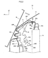
- Fig. 1 is a schematic perspective view illustrating a vehicle front section to which a vehicle front section structure according to a first exemplary embodiment of the present invention has been applied;
- arrow FR indicates a vehicle front direction
- arrow UP indicates a vehicle top direction
- arrow IN indicates a vehicle width inside direction.
- a vehicle front section structure 10 is provided with a bumper cover 12 extending along a vehicle width direction at a front portion of the vehicle.
- the bumper cover 12 is formed from a resin material with a thin walled profile, and configures a design face of the vehicle front section.
- an upper side of the bumper cover 12 extends upwards and inclines towards the vehicle rear side, and an upper end portion of the bumper cover 12 is disposed facing a front end portion of a hood 14 that covers an engine room at a vehicle body front section.
- the design face of the bumper cover 12 and the design face of the hood 14 are therefore configured such that one continues from the other. Since the upper side of the bumper cover 12 is extended towards the vehicle rear side, the front end portion of the hood 14 is disposed to be relatively retreated towards the vehicle rear side (note that Fig. 2 shows a schematic cross-section of the hood 14).
- a radiator support 16 that is a framework member configuring the vehicle body is disposed at a lower side of the front end portion of the hood 14.
- a radiator not shown in the drawings, is attached to the radiator support 16.
- the upper end portion of the bumper cover 12 is fixed through a bracket, not shown in the drawings, to an upper radiator support 16A that configures an upper portion of the radiator support 16. Note that both vehicle width direction end sides and a bottom end side of the bumper cover 12 are fixed to a vehicle body through brackets or the like, not shown in the drawings.
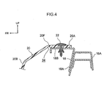
- radiator support brackets 18 serving as attachment members are disposed at a front face side of the upper radiator support 16A along the vehicle width direction.
- the radiator support brackets 18 are formed by bending a sheet metal material into a substantially L-shaped profile (see Fig. 4 ), and each include a joining portion 18A that is welded to the front face of the upper radiator support 16A, and a grille attachment portion 18B extending integrally from a top end of the joining portion 18A towards the vehicle front side.
- a radiator grille 20 is attached to the radiator support brackets 18.
- the radiator grille 20 is formed from a resin material having higher rigidity than the bumper cover 12, and lower rigidity than the radiator support brackets 18, and is disposed at the vehicle rear side of the bumper cover 12.
- the radiator grille 20 is provided with a plate shaped fixed portion 20A that is supported from below by the grille attachment portions 18B of the radiator support bracket 18.
- the fixed portion 20A is fixed to the radiator support bracket 18 by clips 22 that pass through the fixed portion 20A and the grille attachment portions 18B.
- screws or bolts may be used in place of the clips 22.
- a grille main body portion 20B extends integrally from a front end of the fixed portion 20A, inclined downwards towards the vehicle front side.
- a lower portion side of the grille main body portion 20B is formed with a lattice pattern corresponding to a lattice portion 12A formed at the bumper cover 12, and fits into the lattice portion 12A of the bumper cover 12 from the vehicle rear side.
- the bumper cover 12 is consequently supported from the vehicle rear side by the radiator grille 20.
- a plate shaped lower side extension portion 20C extends from a bottom edge of the grille main body portion 20B, inclined downwards towards the vehicle rear side.
- a contact portion 20D is provided at a lower side of the lower side extension portion 20C.
- the contact portion 20D is provided with a plate shaped vertical wall 24 extending integrally from a bottom edge of the lower side extension portion 20C towards the vehicle lower side.
- a plate shaped horizontal wall 26 extends integrally from a bottom edge of the vertical wall 24 towards the vehicle front side.
- Plural plate shaped ribs 28 integrally connect the front face of the vertical wall 24 and the top face of the horizontal wall 26.
- the ribs 28 are disposed in a row along the vehicle width direction with a plate thickness direction aligned with the vehicle width direction.
- the vertical wall 24 and the horizontal wall 26 are accordingly reinforced by the ribs 28.
- a contact side weakened portion 20E is provided between the vertical wall 24 of the contact portion 20D and the lower side extension portion 20C.
- the contact side weakened portion 20E is formed with a groove 30 extending in the vehicle width direction on a front face of the radiator grille 20 between the vertical wall 24 and the lower side extension portion 20C.
- the contact side weakened portion 20E is formed by thinning the wall such that the radiator grille 20 is weakened at a location of the contact side weakened portion 20E.
- a bumper reinforcement 32 is disposed to the vehicle rear side of the contact portion 20D described above, as a framework member provided at a vehicle body front section. A top end portion of the bumper reinforcement 32 is disposed facing the contact portion 20D and separated therefrom by a small gap at the vehicle rear side of the contact portion 20D. Note that the gap is set with dimensions such that the contact portion 20D and the bumper reinforcement 32 do not unintentionally interfere with one another during normal vehicle use.
- the radiator grille 20 described above is formed to be curved as viewed from the vehicle top-bottom direction, such that a vehicle width direction central part bulges out further towards the vehicle front side than vehicle width direction end sides.
- a weakened portion for rotation 20F (planned bending portion, see Fig. 3 ) is also provided between the fixed portion 20A and the grille main body portion 20B (note that for ease of explanation, the weakened portion for rotation 20F is shown by a bold dotted line in Fig. 3 ).
- the weakened portion for rotation 20F is formed by a groove 34 (see Fig.
- the weakened portion for rotation 20F is formed with a curved line shape when viewed from the vehicle top-bottom direction, curving such that a vehicle width direction central part is positioned further towards the vehicle front side than vehicle width direction end sides.
- the weakened portion for rotation 20F is disposed facing front ends of each of the radiator support brackets 18. In other words, when viewed from the vehicle top-bottom direction, the weakened portion for rotation 20F is disposed so as to locate at a front end portion of each of the radiator support brackets 18.
- configuration may be made in another exemplary embodiment such that a weakened portion for rotation (planned bending portion) is provided to the radiator grille 20 by forming, for example, slits or holes between the fixed portion 20A and the grille main body portion 20B.
- the weakened portion for rotation 20F is thus provided to the radiator grille 20.
- the grille main body portion 20B accordingly is moved to rotate along with the lower side extension portion 20C and the contact portion 20D, towards a retreat position (the position shown by the single-dashed intermittent lines in Fig. 2 ) at the vehicle rear side, by the weakened portion for rotation 20F bending when load is input to the grille main body portion 20B of the radiator grille 20 from the vehicle front side.
- the grille main body portion 20B, the lower side extension portion 20C and the contact portion 20D rotate towards the vehicle rear side relative to the fixed portion 20A that is attached to the radiator support 16, or in other words, relative to the vehicle body side.
- the top end portion of the bumper reinforcement 32 is disposed facing the rear side of the contact portion 20D as described above. Therefore, when the contact portion 20D rotates towards the vehicle rear side as described above, the contact portion 20D comes into contact with the top end portion of the bumper reinforcement 32. Note that the contact portion 20D comes into contact with the bumper reinforcement 32 at the stage immediately after starting to rotate together with the grille main body portion 20B towards the retreat position.
- the bumper cover 12 is supported by the grille main body portion 20B of the radiator grille 20 from the vehicle rear side. Accordingly, when, for example, an impacting body 36 collides with the bumper cover 12 from diagonally above the vehicle front side, load is input to the grille main body portion 20B from the vehicle front side towards the vehicle rear side.
- the weakened portion for rotation 20F provided between the fixed portion 20A and the grille main body portion 20B of the radiator grille 20 accordingly bends, and the grille main body portion 20B is moved to rotate together with the lower side extension portion 20C and the contact portion 20D towards the retreat position on the vehicle rear side.
- the contact portion 20D since the top end portion of the bumper reinforcement 32 is disposed facing the vehicle rear side of the contact portion 20D, when the contact portion 20D rotates towards the vehicle rear side together with the grille main body portion 20B etc. as described above, the contact portion 20D comes into contact with the top end portion of the bumper reinforcement 32. The rotation of the grille main body portion 20B towards the vehicle rear side is therefore obstructed, and a load imparted to the impacting body 36 from the bumper cover 12 increases.
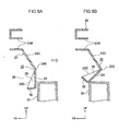
- the contact side weakened portion 20E when a load of a set value or above is input the contact side weakened portion 20E by the above contact of the contact portion 20D and the top end portion of the bumper reinforcement 32, the contact portion 20D folds up and slides past the bumper reinforcement 32 (the contact released state between the contact portion 20D and the bumper reinforcement 32, see the double-dashed intermittent lines in Fig. 2 , and Fig. 5B ) due to the contact side weakened portion 20E bending.
- the grille main body portion 20B is therefore allowed to rotate as far as the retreat position, reducing the load imparted to the impacting body 36 from the bumper cover 12.
- the first exemplary embodiment can accordingly reduce the maximum load acting on the impacting body 36.
- the F-S line graph shown in Fig. 6 illustrates by the curved line C1 the relationship between the load that the impacting body 36 receives from the bumper cover 12 and a displacement of the impacting body 36.
- Point A in Fig. 6 illustrates the relationship between the load acting on the impacting body 36 and a movement stroke when the contact portion 20D has made contact with the bumper reinforcement 32
- point B illustrates the relationship between the load acting on the impacting body 36 and the movement stroke when the contact side weakened portion 20E is bending.
- a range indicated by E in Fig. 6 shows an "initial period" of the rotation of the grille main body portion 20B.
- the load that the impacting body receives from the bumper cover 12 increases as far as a specific maximum load F max , after which it immediately starts to decrease.
- the maximum load F max can be set in advance, and is based on a load which is input to bend the contact side weakened portion 20E when contact is made between the contact portion 20D and the bumper reinforcement 32.
- the maximum load F max acting on the impacting body 36 can accordingly be adjusted by appropriately changing setting of a bending rigidity of the contact side weakened portion 20E.
- the contact portion 20D of the radiator grille 20 is disposed facing the top end portion of the bumper reinforcement 32 and separated therefrom by a small gap. Therefore, the contact portion 20D comes into contact with the top end portion of the bumper reinforcement 32 immediately after rotational displacement starts when the contact portion 20D moves towards the vehicle rear side together with the grille main body portion 20B etc. as described above. Consequently, the load acting on the impacting body 36 in the initial period can be made to rapidly rise to the maximum load F max and then start decreasing. Accordingly, even in cases where the impacting body 36 goes on to further collides with the hood 14, the increase in the load received by the impacting body 36 from the hood 14 (see the curved line C2 in Fig.
- the first exemplary embodiment can therefore improve impacting body protection performance (in particular, the protection performance with respect to a thigh region of a pedestrian).
- the configuration of the contact release section in the first exemplary embodiment can also be kept simple as the contact side weakened portion 20E provided to the radiator grille 20 is bent (deformed) thereby releasing the contact state between the contact portion 20D and the bumper reinforcement 32.
- the weakened portion for rotation 20F provided to the radiator grille 20 is formed as a curved line following a curvature of the front side face of the radiator grille 20.
- the weakened portion for rotation 20F can alleviate any effects of difficulty in bending the radiator grille 20 which may be caused as the front face side of the radiator grille 20 is curved.
- the radiator grille 20 can accordingly be bent around the weakened portion for rotation 20F in a desirable fashion.
- a simple configuration can also be achieved for the planned bending portion since it is sufficient merely to provide a weakened portion (the weakened portion for rotation 20F) to the radiator grille 20.
- the weakened portion for rotation 20F of the radiator grille Due to disposing the weakened portion for rotation 20F of the radiator grille facing the front end portions of the respective radiator support brackets 18 in the first exemplary embodiment, stress can be concentrated on the weakened portion for rotation 20F when load is input to the grille main body portion 20B of the radiator grille 20.
- the radiator grille 20 can accordingly be bent around the weakened portion for rotation 20F in a desirable fashion.
- the contact portion 20D of the radiator grille 20 also comes into contact with the bumper reinforcement 32 provided at the lower side of the radiator grille 20.
- the contact portion 20D can therefore be caused to make contact with the bumper reinforcement 32 immediately after the grille main body portion 20B begins to be rotationally displaced. This is preferable as the initial load acting on the impacting body 36 is rapidly risen.
- Deformation of the contact portion 20D by reaction force from the bumper reinforcement 32 can be suppressed in the first exemplary embodiment due to the contact portion 20D of the radiator grille 20 being reinforced by the ribs 28. Load can therefore be input effectively to the contact side weakened portion 20E, enabling the contact side weakened portion 20E to be folded up as intended.
- Fig. 7 shows a schematic perspective view of a radiator grille 40 that is a configuration member of a vehicle front section structure according to a second exemplary embodiment of the present invention.
- a radiator grille 40 of the present second exemplary embodiment has the same basic configuration as the radiator grille 20 of the first exemplary embodiment. However, in place of the weakened portion for rotation 20F of the first exemplary embodiment, the radiator grille 40 is provided with plural (3 in this case) weakened portions for rotation 20F1, 20F2, 20F3 (all of which are planned bending portions) formed as straight lines in a row along the vehicle width direction. (Note that for ease of explanation, the weakened portions for rotation 20F1, 20F2, 20F3 are shown by bold dotted lines in Fig. 7 ).
- the weakened portions for rotation 20F1, 20F2, 20F3 are formed as plural (3 in this case) grooves along the vehicle width direction on a back face of a radiator grille 40 between a fixed portion 20A and a grille main body portion 20B.
- the grooves are formed by thinning a wall to weaken the radiator grille 40 between the fixed portion 20A and the grille main body portion 20B.
- the weakened portions for rotation 20F1, 20F2, 20F3 are disposed facing front end portions of the previously described radiator support brackets 18.
- the weakened portion for rotation 20F2 disposed at a vehicle width direction central portion of the radiator grille 40 and is formed parallel to the vehicle width direction.
- the weakened portions for rotation 20F1, 20F3 disposed at the vehicle width direction end sides of the radiator grill 40 are slightly inclined with respect to the vehicle width direction, such that their respective outer side end portions in the vehicle width direction are disposed slightly further to a vehicle rear direction side than their inner side end portions.
- the weakened portions for rotation 20F, 20F2, 20F3 are accordingly disposed in a row along the vehicle width direction so as to follow a curvature of the front face side of the radiator grille 40.
- the grille main body portion 20B of the radiator grille 40 When a load is input to the grille main body portion 20B of the radiator grille 40 from the vehicle front side, the grille main body portion 20B, the lower side extension portion 20C and the contact portion 20D are displaced to rotate together towards a retreat position (the position shown by the single-dashed intermittent lines in Fig. 2 ) at the vehicle rear side due to one or more of the weakened portions for rotation 20F1, 20F2, 20F3 bending.
- the weakened portions for rotation 20F1, 20F2, 20F3 of the radiator grille 40 are formed as straight lines and provided in a row along the vehicle width direction so as to follow the curvature of the front side of the radiator grille 40, the weakened portions for rotation 20F1, 20F2, 20F3 can reduce the effects of any difficulty in bending the radiator grille 20 caused by the front face side of the radiator grille 20 which has a curved shape.
- the radiator grille 40 can accordingly be bent around the weakened portions for rotation 20F1, 20F2, 20F3 in a desirable fashion.
- the weakened portions for rotation 20F1, 20F2, 20F3 of the radiator grille facing the front ends of the respective radiator support brackets 18 in the second exemplary embodiment, stress can be concentrated on the weakened portions for rotation 20F1, 20F2, 20F3 when load is input to the grille main body portion 20B of the radiator grille 40.
- the radiator grille 40 can accordingly be bent around the weakened portions for rotation 20F1, 20F2, 20F3 in a desirable fashion.
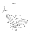
- Fig. 8 shows a schematic perspective view of a radiator grille 50 that is a configuration member of a vehicle front section structure according to a third exemplary embodiment of the present invention.
- Fig. 9A shows a vertical cross-section taken along line 9-9 in Fig. 8 .
- a radiator grille 50 of the third exemplary embodiment has the same basic configuration as the radiator grille 20 of the first exemplary embodiment. However in the radiator grille 50 a vehicle width direction central portion of a grille main body portion 20B is formed with a plate shape (the lattice is omitted).
- a lower side extension portion 20C also extends from a lower edge of the grille main body portion 20B towards the vehicle bottom side.
- a bottom edge of the lower side extension portion 20C is curved, as viewed along the vehicle front-rear direction, such that a vehicle width direction central portion thereof projects out further towards the vehicle bottom side than vehicle width direction end sides thereof.
- a vertical wall 24 of a contact portion 20D is integrally connected to the vehicle width direction central portion of the lower side extension portion 20C. Notches 52, 54 are consequently formed between the contact portion 20D and the lower side extension portion 20C.
- connection portion between the contact portion 20D and the lower side extension portion 20C is formed with a thin plate profile.
- a contact side weakened portion 20G is thereby provided between the lower side extension portion 20C and the contact portion 20D.
- the contact side weakened portion 20G is configured to rupture across from the notches 52, 54 when a load of a preset value or greater acts on the contact side weakened portion 20G.
- the grille main body portion 20B is moved to rotate together with the lower side extension portion 20C and the contact portion 20D towards the vehicle rear side when load is input from the vehicle front side to the grille main body portion 20B of the radiator grille 50.
- the contact portion 20D accordingly contacts the top end portion of the bumper reinforcement 32.
- the contact side weakened portion 20G ruptures and the contact portion 20D falls away, as shown in Fig. 9B .
- the above contact state is thereby released, allowing rotation of the grille main body portion 20B towards the retreat position.
- the operation and advantageous effects of the present exemplary embodiment are accordingly basically the same as those of the first exemplary embodiment.
- radiator grilles 20, 40, 50 according to each of the exemplary embodiments above are respectively configured with the weakened portion for rotation 20F and the weakened portions for rotation 20F1, 20F2, 20F3 disposed facing front end portions of the radiator support brackets 18, the invention is not limited thereto. It is sufficient to dispose the weakened portion(s) for rotation (planned bending portion(s)) anywhere between the fixed portion 20A and the grille main body portion 20B.
- configuration is such that the weakened portion(s) for rotation (planned bending portion(s)) is positioned between the leading end of the extending portion of the fixed portion 20A and the grille main body portion 20B.
- Each of the above exemplary embodiments is respectively configured with the weakened portion for rotation 20F, or the weakened portions for rotation 20F1, 20F2, 20F3, as weakened portion(s) that serve as the planned bending portion, however the invention is not limited thereto. Any configuration may be made in which the planned bending section bends when a load of a preset value or greater is input from the vehicle front side to the grille main body portion 20B, thereby permitting the grille main body portion 20B to be moved to rotate towards the vehicle rear side.
- radiator grilles 20, 40, 50 of each of the above exemplary embodiments are configured with a curve as viewed from the vehicle top-bottom direction, the invention is not limited thereto, and the shape of the radiator grille may be altered as appropriate.
- the bumper reinforcement 32 serves as a vehicle body side member
- the invention is not limited thereto. Any member that is either part of the vehicle body or is attached to the vehicle body, and that has a sufficient degree of rigidity such that the contact side weakened portion 20E is caused to bend when the member makes contact with the contact portion 20D may be employed as the vehicle body side member.
- the contact portion 20D is provided at a bottom edge portion of the radiator grille 20 in each of the above exemplary embodiments, however the invention is not limited thereto and where the contact portion is disposed may be varied as appropriate.
- the contact release section is configured by the contact side weakened portions 20E, 20G that bend (deform) or rupture, however the invention is not limited thereto.
- the contact portion 20D is made to contact a vehicle body side member attached for example to the bumper reinforcement 32 (vehicle body side)
- configuration may be made such that the contact state between the contact portion 20D and the vehicle body side member is released by causing the vehicle body side member to move with respect to the vehicle body against for example a frictional force.
Landscapes
- Engineering & Computer Science (AREA)
- Mechanical Engineering (AREA)
- Chemical & Material Sciences (AREA)
- Combustion & Propulsion (AREA)
- Transportation (AREA)
- Body Structure For Vehicles (AREA)
Claims (9)
- Structure (10) de section avant de véhicule comprenant :un couvercle de pare-chocs (12) s'étendant dans la direction de la largeur de véhicule au niveau d'une section avant de véhicule ;une grille (20) de radiateur disposée du côté arrière de véhicule par rapport au couvercle de pare-chocs (12) et comprenant :une partie fixe (20A) disposée du côté supérieur de la grille (20) de radiateur, la partie fixe (20A) étant fixée à un élément de fixation au niveau d'un côté de carrosserie de véhicule ;une partie (20B) formant corps principal de grille disposée sous la partie fixe (20A) et supportant le couvercle de pare-chocs (12) à partir du côté dans la direction arrière de véhicule,
caractérisée par :une partie pliante plane (20E, 20F) qui est disposée entre la partie (20B) formant corps principal de grille et la partie fixe (20A), et qui se plie pour permettre à la partie (20B) formant corps principal de grille de tourner en direction d'une position en retrait du côté arrière de véhicule lorsqu'un effort est appliqué à la partie (20B) formant corps principal de grille depuis le côté avant de véhicule ; etune partie (20D) de contact qui fait contact avec un élément latéral (32) de carrosserie de véhicule durant la rotation de la partie (20B) formant corps principal de grille ; etune section (20E) de libération de contact qui libère l'état de contact de la partie (20D) de contact avec l'élément latéral (32) de carrosserie de véhicule lorsqu'un effort entré en raison du contact est au moins égal à une valeur fixée. - Structure (10) de section avant de véhicule selon la revendication 1, dans laquelle la section (20E) de libération de contact est une partie affaiblie du côté contact (20E) prévue sur la grille (20) de radiateur, et dans laquelle la partie affaiblie du côté contact (20E) se déforme ou se rompt lorsque l'effort entré est au moins égal à la valeur fixée.
- Structure (10) de section avant de véhicule selon soit la revendication 1 soit la revendication 2, dans laquelle la partie pliante plane (20E, 20F) est formée avec un profil curviligne vu depuis la direction haut-bas de sorte qu'une pièce centrale dans la direction de la largeur de véhicule de la partie pliante plane (20E, 20F) est placée davantage vers le côté avant de véhicule que les côtés d'extrémité dans la direction de la largeur de véhicule de la partie pliante plane (20E, 20F).
- Structure (10) de section avant de véhicule selon soit la revendication 1 soit la revendication 2, dans laquelle la grille (20) de radiateur est formée avec une courbure du côté de la face avant, vue depuis la direction haut-bas de véhicule, et la grille (20) de radiateur est pourvue d'une partie pliante plane (20E, 20F) formée comme une unique ligne droite disposée suivant la direction de la largeur de véhicule, ou bien la grille (20) de radiateur est pourvue d'une pluralité de parties pliantes planes (20E, 20F) formées comme des lignes droites disposées en une rangée suivant la direction de la largeur de véhicule de façon à suivre la courbure du côté de face avant de la grille (20) de radiateur.
- Structure (10) de section avant de véhicule selon l'une quelconque de la revendication 1 à la revendication 4, dans laquelle l'élément latéral de carrosserie de véhicule est disposé à une position propre à faire contact avec la partie (20D) de contact au moment d'une période initiale de la rotation.
- Structure (10) de section avant de véhicule selon l'une quelconque de la revendication 1 à la revendication 5, dans laquelle l'élément latéral de carrosserie de véhicule est un renfort de pare-chocs, et la partie (20D) de contact est disposée à la partie de bord inférieur de la grille (20) de radiateur.
- Structure (10) de section avant de véhicule selon l'une quelconque de la revendication 1 à la revendication 6, dans laquelle la partie pliante plane (20E, 20F) est une partie affaiblie pour rotation là où la grille (20) de radiateur est réalisée plus faible entre la partie (20B) formant corps principal de grille et la partie fixe (20A).
- Structure (10) de section avant de véhicule selon la revendication 7, dans laquelle l'élément de fixation est réalisé avec une rigidité plus grande que la grille (20) de radiateur, et dans laquelle la partie affaiblie pour rotation est disposée en face d'une partie d'extrémité de l'élément de fixation.
- Structure (10) de section avant de véhicule selon l'une quelconque de la revendication 1 à la revendication 8, dans laquelle l'élément latéral de carrosserie de véhicule fait face à la partie (20D) de contact et est séparé de la partie (20D) de contact par un espace.
Applications Claiming Priority (1)
| Application Number | Priority Date | Filing Date | Title |
|---|---|---|---|
| PCT/JP2010/053048 WO2011104853A1 (fr) | 2010-02-26 | 2010-02-26 | Structure avant de véhicule |
Publications (3)
| Publication Number | Publication Date |
|---|---|
| EP2540577A1 EP2540577A1 (fr) | 2013-01-02 |
| EP2540577A4 EP2540577A4 (fr) | 2013-10-16 |
| EP2540577B1 true EP2540577B1 (fr) | 2014-07-02 |
Family
ID=44506298
Family Applications (1)
| Application Number | Title | Priority Date | Filing Date |
|---|---|---|---|
| EP10846518.8A Not-in-force EP2540577B1 (fr) | 2010-02-26 | 2010-02-26 | Structure de section avant de véhicule |
Country Status (3)
| Country | Link |
|---|---|
| EP (1) | EP2540577B1 (fr) |
| JP (1) | JP5110221B2 (fr) |
| WO (1) | WO2011104853A1 (fr) |
Families Citing this family (9)
| Publication number | Priority date | Publication date | Assignee | Title |
|---|---|---|---|---|
| GB2501467A (en) | 2012-04-05 | 2013-10-30 | Aston Martin Lagonda Ltd | Vehicle grille assembly |
| DE102013208981A1 (de) * | 2013-05-15 | 2014-11-20 | Bayerische Motoren Werke Aktiengesellschaft | Fahrzeug mit einer Grundkarosserie und einem Außenkarosserieteil |
| JP6154249B2 (ja) * | 2013-08-27 | 2017-06-28 | 株式会社Subaru | 車体前部構造 |
| JP2016030522A (ja) * | 2014-07-29 | 2016-03-07 | トヨタ車体株式会社 | ラジエータグリル |
| US9415734B2 (en) | 2015-01-09 | 2016-08-16 | Toyota Motor Engineering & Manufacturing North America, Inc. | Bumper assemblies for vehicles |
| JP6935767B2 (ja) * | 2018-02-15 | 2021-09-15 | トヨタ自動車株式会社 | グリルインナ取付構造 |
| DE102021202608A1 (de) | 2021-03-18 | 2022-09-22 | Volkswagen Aktiengesellschaft | Stützstruktur für eine Außenverkleidung des Frontbereichs eines Kraftfahrzeugs und Frontend-Modul für ein Kraftfahrzeug |
| FR3122155A1 (fr) * | 2021-04-22 | 2022-10-28 | Psa Automobiles Sa | Armature pour le maintien d’un pare-chocs d’un vehicule automobile comprenant une zone de pliage |
| FR3136209B1 (fr) * | 2022-06-07 | 2024-04-19 | Psa Automobiles Sa | Armature de pare-chocs adaptée au choc d’une tête, pour une façade avant de véhicule |
Family Cites Families (17)
| Publication number | Priority date | Publication date | Assignee | Title |
|---|---|---|---|---|
| JPS5634541A (en) * | 1979-08-27 | 1981-04-06 | Nissan Motor Co Ltd | Mounting structure of radiator grill |
| JPS5830874A (ja) * | 1981-08-17 | 1983-02-23 | Nissan Motor Co Ltd | 車体前部構造 |
| US5478127A (en) * | 1994-01-28 | 1995-12-26 | Lacks Industries, Inc. | Compliant attachments for a hood-mounted flexible grille |
| JP3791703B2 (ja) * | 1995-10-31 | 2006-06-28 | マツダ株式会社 | 自動車のグリル取り付け構造 |
| JP3624551B2 (ja) * | 1996-06-24 | 2005-03-02 | マツダ株式会社 | 自動車のフロントバンパー構造 |
| JP3717820B2 (ja) * | 2001-09-14 | 2005-11-16 | 本田技研工業株式会社 | 車両用フロントグリル衝撃吸収構造 |
| JP3642754B2 (ja) * | 2001-09-14 | 2005-04-27 | 本田技研工業株式会社 | 車両の水冷エンジン用ラジエータ上部取付構造 |
| DE10350294B4 (de) * | 2002-10-24 | 2007-12-20 | Decoma (Germany) Gmbh | Kühlergrillanordnung für ein Kraftfahrzeug |
| JP2004203183A (ja) * | 2002-12-25 | 2004-07-22 | Toyota Motor Corp | 車両の前部車体構造 |
| JP4349243B2 (ja) | 2004-09-09 | 2009-10-21 | トヨタ自動車株式会社 | 車両前部構造 |
| JP4389847B2 (ja) * | 2005-06-27 | 2009-12-24 | トヨタ自動車株式会社 | 車両の前面部構造 |
| JP4434096B2 (ja) * | 2005-07-11 | 2010-03-17 | トヨタ自動車株式会社 | バンパ構造 |
| JP4843630B2 (ja) * | 2008-03-14 | 2011-12-21 | 本田技研工業株式会社 | 車両のフロント構造 |
| JP5087461B2 (ja) * | 2008-04-17 | 2012-12-05 | 本田技研工業株式会社 | 車両の車体前部構造 |
| JP5056588B2 (ja) * | 2008-05-29 | 2012-10-24 | スズキ株式会社 | 自動車のフロントグリル構造 |
| JP2010000881A (ja) * | 2008-06-19 | 2010-01-07 | Kanto Auto Works Ltd | 自動車のフロントグリルの取付部構造 |
| JP4991645B2 (ja) * | 2008-06-26 | 2012-08-01 | 本田技研工業株式会社 | 車体前部の衝撃吸収構造 |
-
2010
- 2010-02-26 WO PCT/JP2010/053048 patent/WO2011104853A1/fr active Application Filing
- 2010-02-26 EP EP10846518.8A patent/EP2540577B1/fr not_active Not-in-force
- 2010-02-26 JP JP2012501584A patent/JP5110221B2/ja not_active Expired - Fee Related
Also Published As
| Publication number | Publication date |
|---|---|
| JPWO2011104853A1 (ja) | 2013-06-17 |
| EP2540577A4 (fr) | 2013-10-16 |
| JP5110221B2 (ja) | 2012-12-26 |
| EP2540577A1 (fr) | 2013-01-02 |
| WO2011104853A1 (fr) | 2011-09-01 |
Similar Documents
| Publication | Publication Date | Title |
|---|---|---|
| EP2540577B1 (fr) | Structure de section avant de véhicule | |
| JP4470607B2 (ja) | 車両用フード構造 | |
| US8307935B2 (en) | Vehicle pop up hood apparatus | |
| JP4872541B2 (ja) | 自動車のバンパ構造 | |
| EP1726490B1 (fr) | Structure de partie avant de carrosserie d'un véhicule | |
| EP2647552B1 (fr) | Panneau intérieur de capot | |
| JP5499056B2 (ja) | 車両用バンパ構造 | |
| JP2005096629A (ja) | 車両用フード構造 | |
| CN106114642B (zh) | 用于支承车辆的外部装饰部件的支承结构 | |
| JP6090206B2 (ja) | バンパカバーリテーナ、ラジエータグリル及び車両前部構造 | |
| JP3956846B2 (ja) | 自動車の前部構造 | |
| US8628113B2 (en) | Side impact absorbing apparatus for vehicle | |
| JP2006111249A (ja) | エンジンアンダカバー取付構造 | |
| EP2008884A1 (fr) | Capot pour véhicules à moteur | |
| JP4457909B2 (ja) | カウルルーバ | |
| JP4685906B2 (ja) | 車両用フード構造 | |
| JP6558384B2 (ja) | 車両の前部構造 | |
| US7097221B2 (en) | Bumper having a roll-formed ridge | |
| JP6076798B2 (ja) | 自動車の前部車体構造 | |
| JP5520081B2 (ja) | 自動車のカウル構造 | |
| CN210437270U (zh) | 一种汽车翼子板及车辆 | |
| JP6001481B2 (ja) | 車体前部構造 | |
| JP2014111400A (ja) | 自動車の脚払い構造 | |
| JP3915433B2 (ja) | 自動車用バンパー | |
| JP5777472B2 (ja) | 車両用フードの衝撃力吸収構造 |
Legal Events
| Date | Code | Title | Description |
|---|---|---|---|
| PUAI | Public reference made under article 153(3) epc to a published international application that has entered the european phase |
Free format text: ORIGINAL CODE: 0009012 |
|
| 17P | Request for examination filed |
Effective date: 20120821 |
|
| AK | Designated contracting states |
Kind code of ref document: A1 Designated state(s): AT BE BG CH CY CZ DE DK EE ES FI FR GB GR HR HU IE IS IT LI LT LU LV MC MK MT NL NO PL PT RO SE SI SK SM TR |
|
| RAP1 | Party data changed (applicant data changed or rights of an application transferred) |
Owner name: TOYOTA JIDOSHA KABUSHIKI KAISHA |
|
| DAX | Request for extension of the european patent (deleted) | ||
| A4 | Supplementary search report drawn up and despatched |
Effective date: 20130918 |
|
| RIC1 | Information provided on ipc code assigned before grant |
Ipc: B60R 19/02 20060101ALI20130912BHEP Ipc: B60R 19/52 20060101AFI20130912BHEP |
|
| GRAP | Despatch of communication of intention to grant a patent |
Free format text: ORIGINAL CODE: EPIDOSNIGR1 |
|
| INTG | Intention to grant announced |
Effective date: 20140116 |
|
| GRAS | Grant fee paid |
Free format text: ORIGINAL CODE: EPIDOSNIGR3 |
|
| GRAA | (expected) grant |
Free format text: ORIGINAL CODE: 0009210 |
|
| RIN1 | Information on inventor provided before grant (corrected) |
Inventor name: OTSUKA, RYUJI |
|
| AK | Designated contracting states |
Kind code of ref document: B1 Designated state(s): AT BE BG CH CY CZ DE DK EE ES FI FR GB GR HR HU IE IS IT LI LT LU LV MC MK MT NL NO PL PT RO SE SI SK SM TR |
|
| REG | Reference to a national code |
Ref country code: GB Ref legal event code: FG4D |
|
| REG | Reference to a national code |
Ref country code: CH Ref legal event code: EP Ref country code: AT Ref legal event code: REF Ref document number: 675733 Country of ref document: AT Kind code of ref document: T Effective date: 20140715 |
|
| REG | Reference to a national code |
Ref country code: IE Ref legal event code: FG4D |
|
| REG | Reference to a national code |
Ref country code: DE Ref legal event code: R096 Ref document number: 602010017305 Country of ref document: DE Effective date: 20140814 |
|
| REG | Reference to a national code |
Ref country code: AT Ref legal event code: MK05 Ref document number: 675733 Country of ref document: AT Kind code of ref document: T Effective date: 20140702 |
|
| REG | Reference to a national code |
Ref country code: DE Ref legal event code: R084 Ref document number: 602010017305 Country of ref document: DE |
|
| REG | Reference to a national code |
Ref country code: NL Ref legal event code: VDEP Effective date: 20140702 |
|
| REG | Reference to a national code |
Ref country code: GB Ref legal event code: 746 Effective date: 20141119 |
|
| REG | Reference to a national code |
Ref country code: LT Ref legal event code: MG4D |
|
| REG | Reference to a national code |
Ref country code: DE Ref legal event code: R084 Ref document number: 602010017305 Country of ref document: DE Effective date: 20141117 |
|
| PG25 | Lapsed in a contracting state [announced via postgrant information from national office to epo] |
Ref country code: BG Free format text: LAPSE BECAUSE OF FAILURE TO SUBMIT A TRANSLATION OF THE DESCRIPTION OR TO PAY THE FEE WITHIN THE PRESCRIBED TIME-LIMIT Effective date: 20141002 Ref country code: PT Free format text: LAPSE BECAUSE OF FAILURE TO SUBMIT A TRANSLATION OF THE DESCRIPTION OR TO PAY THE FEE WITHIN THE PRESCRIBED TIME-LIMIT Effective date: 20141103 Ref country code: LT Free format text: LAPSE BECAUSE OF FAILURE TO SUBMIT A TRANSLATION OF THE DESCRIPTION OR TO PAY THE FEE WITHIN THE PRESCRIBED TIME-LIMIT Effective date: 20140702 Ref country code: ES Free format text: LAPSE BECAUSE OF FAILURE TO SUBMIT A TRANSLATION OF THE DESCRIPTION OR TO PAY THE FEE WITHIN THE PRESCRIBED TIME-LIMIT Effective date: 20140702 Ref country code: SE Free format text: LAPSE BECAUSE OF FAILURE TO SUBMIT A TRANSLATION OF THE DESCRIPTION OR TO PAY THE FEE WITHIN THE PRESCRIBED TIME-LIMIT Effective date: 20140702 Ref country code: CZ Free format text: LAPSE BECAUSE OF FAILURE TO SUBMIT A TRANSLATION OF THE DESCRIPTION OR TO PAY THE FEE WITHIN THE PRESCRIBED TIME-LIMIT Effective date: 20140702 Ref country code: NO Free format text: LAPSE BECAUSE OF FAILURE TO SUBMIT A TRANSLATION OF THE DESCRIPTION OR TO PAY THE FEE WITHIN THE PRESCRIBED TIME-LIMIT Effective date: 20141002 Ref country code: GR Free format text: LAPSE BECAUSE OF FAILURE TO SUBMIT A TRANSLATION OF THE DESCRIPTION OR TO PAY THE FEE WITHIN THE PRESCRIBED TIME-LIMIT Effective date: 20141003 Ref country code: FI Free format text: LAPSE BECAUSE OF FAILURE TO SUBMIT A TRANSLATION OF THE DESCRIPTION OR TO PAY THE FEE WITHIN THE PRESCRIBED TIME-LIMIT Effective date: 20140702 |
|
| REG | Reference to a national code |
Ref country code: FR Ref legal event code: PLFP Year of fee payment: 6 |
|
| PG25 | Lapsed in a contracting state [announced via postgrant information from national office to epo] |
Ref country code: IS Free format text: LAPSE BECAUSE OF FAILURE TO SUBMIT A TRANSLATION OF THE DESCRIPTION OR TO PAY THE FEE WITHIN THE PRESCRIBED TIME-LIMIT Effective date: 20141102 Ref country code: AT Free format text: LAPSE BECAUSE OF FAILURE TO SUBMIT A TRANSLATION OF THE DESCRIPTION OR TO PAY THE FEE WITHIN THE PRESCRIBED TIME-LIMIT Effective date: 20140702 Ref country code: LV Free format text: LAPSE BECAUSE OF FAILURE TO SUBMIT A TRANSLATION OF THE DESCRIPTION OR TO PAY THE FEE WITHIN THE PRESCRIBED TIME-LIMIT Effective date: 20140702 Ref country code: PL Free format text: LAPSE BECAUSE OF FAILURE TO SUBMIT A TRANSLATION OF THE DESCRIPTION OR TO PAY THE FEE WITHIN THE PRESCRIBED TIME-LIMIT Effective date: 20140702 Ref country code: HR Free format text: LAPSE BECAUSE OF FAILURE TO SUBMIT A TRANSLATION OF THE DESCRIPTION OR TO PAY THE FEE WITHIN THE PRESCRIBED TIME-LIMIT Effective date: 20140702 Ref country code: CY Free format text: LAPSE BECAUSE OF FAILURE TO SUBMIT A TRANSLATION OF THE DESCRIPTION OR TO PAY THE FEE WITHIN THE PRESCRIBED TIME-LIMIT Effective date: 20140702 Ref country code: NL Free format text: LAPSE BECAUSE OF FAILURE TO SUBMIT A TRANSLATION OF THE DESCRIPTION OR TO PAY THE FEE WITHIN THE PRESCRIBED TIME-LIMIT Effective date: 20140702 |
|
| REG | Reference to a national code |
Ref country code: DE Ref legal event code: R097 Ref document number: 602010017305 Country of ref document: DE |
|
| PG25 | Lapsed in a contracting state [announced via postgrant information from national office to epo] |
Ref country code: EE Free format text: LAPSE BECAUSE OF FAILURE TO SUBMIT A TRANSLATION OF THE DESCRIPTION OR TO PAY THE FEE WITHIN THE PRESCRIBED TIME-LIMIT Effective date: 20140702 Ref country code: DK Free format text: LAPSE BECAUSE OF FAILURE TO SUBMIT A TRANSLATION OF THE DESCRIPTION OR TO PAY THE FEE WITHIN THE PRESCRIBED TIME-LIMIT Effective date: 20140702 Ref country code: RO Free format text: LAPSE BECAUSE OF FAILURE TO SUBMIT A TRANSLATION OF THE DESCRIPTION OR TO PAY THE FEE WITHIN THE PRESCRIBED TIME-LIMIT Effective date: 20140702 Ref country code: SK Free format text: LAPSE BECAUSE OF FAILURE TO SUBMIT A TRANSLATION OF THE DESCRIPTION OR TO PAY THE FEE WITHIN THE PRESCRIBED TIME-LIMIT Effective date: 20140702 |
|
| PGFP | Annual fee paid to national office [announced via postgrant information from national office to epo] |
Ref country code: IT Payment date: 20150218 Year of fee payment: 6 |
|
| PLBE | No opposition filed within time limit |
Free format text: ORIGINAL CODE: 0009261 |
|
| STAA | Information on the status of an ep patent application or granted ep patent |
Free format text: STATUS: NO OPPOSITION FILED WITHIN TIME LIMIT |
|
| PGFP | Annual fee paid to national office [announced via postgrant information from national office to epo] |
Ref country code: FR Payment date: 20150210 Year of fee payment: 6 Ref country code: GB Payment date: 20150225 Year of fee payment: 6 |
|
| 26N | No opposition filed |
Effective date: 20150407 |
|
| PG25 | Lapsed in a contracting state [announced via postgrant information from national office to epo] |
Ref country code: BE Free format text: LAPSE BECAUSE OF NON-PAYMENT OF DUE FEES Effective date: 20150228 |
|
| PG25 | Lapsed in a contracting state [announced via postgrant information from national office to epo] |
Ref country code: LU Free format text: LAPSE BECAUSE OF FAILURE TO SUBMIT A TRANSLATION OF THE DESCRIPTION OR TO PAY THE FEE WITHIN THE PRESCRIBED TIME-LIMIT Effective date: 20150226 |
|
| REG | Reference to a national code |
Ref country code: CH Ref legal event code: PL |
|
| PG25 | Lapsed in a contracting state [announced via postgrant information from national office to epo] |
Ref country code: MC Free format text: LAPSE BECAUSE OF FAILURE TO SUBMIT A TRANSLATION OF THE DESCRIPTION OR TO PAY THE FEE WITHIN THE PRESCRIBED TIME-LIMIT Effective date: 20140702 Ref country code: LI Free format text: LAPSE BECAUSE OF NON-PAYMENT OF DUE FEES Effective date: 20150228 Ref country code: CH Free format text: LAPSE BECAUSE OF NON-PAYMENT OF DUE FEES Effective date: 20150228 |
|
| REG | Reference to a national code |
Ref country code: IE Ref legal event code: MM4A |
|
| PG25 | Lapsed in a contracting state [announced via postgrant information from national office to epo] |
Ref country code: SI Free format text: LAPSE BECAUSE OF FAILURE TO SUBMIT A TRANSLATION OF THE DESCRIPTION OR TO PAY THE FEE WITHIN THE PRESCRIBED TIME-LIMIT Effective date: 20140702 |
|
| PG25 | Lapsed in a contracting state [announced via postgrant information from national office to epo] |
Ref country code: IE Free format text: LAPSE BECAUSE OF NON-PAYMENT OF DUE FEES Effective date: 20150226 |
|
| PG25 | Lapsed in a contracting state [announced via postgrant information from national office to epo] |
Ref country code: BE Free format text: LAPSE BECAUSE OF FAILURE TO SUBMIT A TRANSLATION OF THE DESCRIPTION OR TO PAY THE FEE WITHIN THE PRESCRIBED TIME-LIMIT Effective date: 20140702 |
|
| GBPC | Gb: european patent ceased through non-payment of renewal fee |
Effective date: 20160226 |
|
| REG | Reference to a national code |
Ref country code: FR Ref legal event code: ST Effective date: 20161028 |
|
| PG25 | Lapsed in a contracting state [announced via postgrant information from national office to epo] |
Ref country code: IT Free format text: LAPSE BECAUSE OF NON-PAYMENT OF DUE FEES Effective date: 20160226 Ref country code: MT Free format text: LAPSE BECAUSE OF FAILURE TO SUBMIT A TRANSLATION OF THE DESCRIPTION OR TO PAY THE FEE WITHIN THE PRESCRIBED TIME-LIMIT Effective date: 20140702 |
|
| PG25 | Lapsed in a contracting state [announced via postgrant information from national office to epo] |
Ref country code: FR Free format text: LAPSE BECAUSE OF NON-PAYMENT OF DUE FEES Effective date: 20160229 Ref country code: GB Free format text: LAPSE BECAUSE OF NON-PAYMENT OF DUE FEES Effective date: 20160226 |
|
| PGFP | Annual fee paid to national office [announced via postgrant information from national office to epo] |
Ref country code: DE Payment date: 20170221 Year of fee payment: 8 |
|
| PG25 | Lapsed in a contracting state [announced via postgrant information from national office to epo] |
Ref country code: SM Free format text: LAPSE BECAUSE OF FAILURE TO SUBMIT A TRANSLATION OF THE DESCRIPTION OR TO PAY THE FEE WITHIN THE PRESCRIBED TIME-LIMIT Effective date: 20140702 Ref country code: HU Free format text: LAPSE BECAUSE OF FAILURE TO SUBMIT A TRANSLATION OF THE DESCRIPTION OR TO PAY THE FEE WITHIN THE PRESCRIBED TIME-LIMIT; INVALID AB INITIO Effective date: 20100226 |
|
| PG25 | Lapsed in a contracting state [announced via postgrant information from national office to epo] |
Ref country code: TR Free format text: LAPSE BECAUSE OF FAILURE TO SUBMIT A TRANSLATION OF THE DESCRIPTION OR TO PAY THE FEE WITHIN THE PRESCRIBED TIME-LIMIT Effective date: 20140702 |
|
| PG25 | Lapsed in a contracting state [announced via postgrant information from national office to epo] |
Ref country code: MK Free format text: LAPSE BECAUSE OF FAILURE TO SUBMIT A TRANSLATION OF THE DESCRIPTION OR TO PAY THE FEE WITHIN THE PRESCRIBED TIME-LIMIT Effective date: 20140702 |
|
| REG | Reference to a national code |
Ref country code: DE Ref legal event code: R119 Ref document number: 602010017305 Country of ref document: DE |
|
| PG25 | Lapsed in a contracting state [announced via postgrant information from national office to epo] |
Ref country code: DE Free format text: LAPSE BECAUSE OF NON-PAYMENT OF DUE FEES Effective date: 20180901 |