EP2538443A2 - Semiconductor element, method for manufacturing same, display device, and electronic device - Google Patents
Semiconductor element, method for manufacturing same, display device, and electronic device Download PDFInfo
- Publication number
- EP2538443A2 EP2538443A2 EP12171717A EP12171717A EP2538443A2 EP 2538443 A2 EP2538443 A2 EP 2538443A2 EP 12171717 A EP12171717 A EP 12171717A EP 12171717 A EP12171717 A EP 12171717A EP 2538443 A2 EP2538443 A2 EP 2538443A2
- Authority
- EP
- European Patent Office
- Prior art keywords
- organic semiconductor
- source
- semiconductor layer
- drain electrodes
- electrode
- Prior art date
- Legal status (The legal status is an assumption and is not a legal conclusion. Google has not performed a legal analysis and makes no representation as to the accuracy of the status listed.)
- Withdrawn
Links
Images


Classifications
-
- H—ELECTRICITY
- H10—SEMICONDUCTOR DEVICES; ELECTRIC SOLID-STATE DEVICES NOT OTHERWISE PROVIDED FOR
- H10K—ORGANIC ELECTRIC SOLID-STATE DEVICES
- H10K10/00—Organic devices specially adapted for rectifying, amplifying, oscillating or switching; Organic capacitors or resistors having potential barriers
- H10K10/80—Constructional details
- H10K10/82—Electrodes
- H10K10/84—Ohmic electrodes, e.g. source or drain electrodes
-
- H—ELECTRICITY
- H10—SEMICONDUCTOR DEVICES; ELECTRIC SOLID-STATE DEVICES NOT OTHERWISE PROVIDED FOR
- H10K—ORGANIC ELECTRIC SOLID-STATE DEVICES
- H10K10/00—Organic devices specially adapted for rectifying, amplifying, oscillating or switching; Organic capacitors or resistors having potential barriers
- H10K10/80—Constructional details
- H10K10/88—Passivation; Containers; Encapsulations
-
- H—ELECTRICITY
- H10—SEMICONDUCTOR DEVICES; ELECTRIC SOLID-STATE DEVICES NOT OTHERWISE PROVIDED FOR
- H10K—ORGANIC ELECTRIC SOLID-STATE DEVICES
- H10K59/00—Integrated devices, or assemblies of multiple devices, comprising at least one organic light-emitting element covered by group H10K50/00
- H10K59/10—OLED displays
- H10K59/12—Active-matrix OLED [AMOLED] displays
- H10K59/125—Active-matrix OLED [AMOLED] displays including organic TFTs [OTFT]
-
- H—ELECTRICITY
- H10—SEMICONDUCTOR DEVICES; ELECTRIC SOLID-STATE DEVICES NOT OTHERWISE PROVIDED FOR
- H10K—ORGANIC ELECTRIC SOLID-STATE DEVICES
- H10K59/00—Integrated devices, or assemblies of multiple devices, comprising at least one organic light-emitting element covered by group H10K50/00
- H10K59/10—OLED displays
- H10K59/12—Active-matrix OLED [AMOLED] displays
- H10K59/131—Interconnections, e.g. wiring lines or terminals
Definitions
- the present disclosure relates to a semiconductor element, a method for manufacturing the same, a display device and an electronic device.
- organic semiconductors such as organic TFTs (Thin Film Transistors) and the like have recently been underway (see C. D. Dimitrakopoulos and P. R. L. Malieri, Adv. Mater. 2002, 14, No. 2, p. 99 , for example).
- the semiconductor elements using the organic semiconductors are assumed to be applied to display devices such as flexible organic EL (Electro Luminescence) displays, flexible electronic papers, and the like as well as electronic devices such as flexible printed boards, organic thin film solar batteries, touch panels, and the like.
- display devices such as flexible organic EL (Electro Luminescence) displays, flexible electronic papers, and the like as well as electronic devices such as flexible printed boards, organic thin film solar batteries, touch panels, and the like.
- an electrode for example a source electrode and a drain electrode
- a wiring layer When an electrode (for example a source electrode and a drain electrode) and a wiring layer are formed on an organic semiconductor layer in a semiconductor element using the organic semiconductor as described above, a break in the wiring layer may occur in the vicinity of end parts of the organic semiconductor layer (edge parts of a semiconductor island), for example.
- contact resistance between the organic semiconductor layer and the electrode or wiring resistance may be increased.
- Such a break in the wiring layer and such an increase in resistance value are factors in manufacturing defects. Therefore the proposition of a method for improving reliability is desired.
- the present disclosure has been made in view of such problems. It is desirable to provide a semiconductor element, a method for manufacturing the same, as well as a display device and an electronic device that can improve reliability.
- the present disclosure relates to a semiconductor element having an organic semiconductor layer, a method for manufacturing the same, and a display device and an electronic device including such a semiconductor element.
- a semiconductor element includes: an organic semiconductor layer; an electrode disposed so as to be in contact with the organic semiconductor layer; and a wiring layer formed separately from the electrode and electrically connected to the electrode.
- a display device includes the semiconductor element according to the above-described embodiment of the present disclosure and a display layer.
- An electronic device includes the display device according to the above-described embodiment of the present disclosure.
- the electrode disposed so as to be in contact with the organic semiconductor layer and the wiring layer electrically connected to the electrode are formed separately from each other. This can prevent a break in the wiring layer in the vicinity of end parts of the organic semiconductor layer (edge parts of a semiconductor island), for example, from occurring easily, and reduce wiring resistance while suppressing contact resistance between the organic semiconductor layer and the electrode, as compared with a case where the electrode and the wiring layer are formed integrally with each other.
- a method for manufacturing a semiconductor element according to an embodiment of the present disclosure includes: forming an organic semiconductor layer and an electrode in contact with the organic semiconductor layer; and forming a wiring layer electrically connected to the electrode.
- the electrode in contact with the organic semiconductor layer is formed, and the wiring layer electrically connected to the electrode is formed.
- This can prevent a break in the wiring layer in the vicinity of end parts of the organic semiconductor layer (edge parts of a semiconductor island), for example, from occurring easily and reduce wiring resistance while suppressing contact resistance between the organic semiconductor layer and the electrode as compared with a case where the electrode and the wiring layer are formed integrally with each other (in a same process).
- the electrode disposed on the organic semiconductor layer so as to be in contact with the organic semiconductor layer and the wiring layer electrically connected to the electrode are formed separately from each other. It is therefore possible to prevent a break in the wiring layer in the vicinity of end parts of the organic semiconductor layer, for example, from occurring easily, and reduce wiring resistance while suppressing contact resistance. Thus, reliability can be improved.
- the electrode is formed on the organic semiconductor layer so as to be in contact with the organic semiconductor layer, and thereafter the wiring layer electrically connected to the electrode is formed. It is therefore possible to prevent a break in the wiring layer in the vicinity of end parts of the organic semiconductor layer, for example, from occurring easily, and reduce wiring resistance while suppressing contact resistance. Thus, reliability can be improved.
- FIGS. 1A and 1B schematically show a general constitution of a semiconductor element (thin film transistor 1) according to a first embodiment of the present disclosure.
- FIG. 1A shows a planar constitution (X-Y planar constitution).
- FIG. 1B shows a sectional constitution (Y-Z sectional constitution) taken along a line II-II in the direction of arrows in FIG. 1A .
- This thin film transistor 1 is of a top-contact staggered type used in an active matrix circuit of a display device, for example.
- the thin film transistor 1 for example has a structure formed by laminating a gate electrode 12, a gate insulating film 13, an organic semiconductor layer 14, a pair of source-drain electrodes 15A and 15B (electrodes), a protective film 16, and a pair of wiring layers 17A and 17B in this order on a substrate 11. That is, the thin film transistor 1 is an organic TFT using an organic semiconductor.
- the substrate 11 is for example formed of an inorganic material such as glass, quartz, silicon, gallium arsenide, or the like, a metallic material, a plastic material, or the like.
- the metallic material includes for example aluminum (Al), nickel (Ni), or stainless steel.
- the plastic material includes polyimide, polyethylene terephthalate (PET), polyethylene naphthalate (PEN), polymethyl methacrylate (PMMA), polycarbonate (PC), polyethersulfone (PES), polyetheretherketone (PEEK), aromatic polyester (liquid crystal polymer), and the like.
- the substrate 11 may be a rigid substrate such as a wafer or the like, or may be a flexible substrate such as a thin layer glass, film, paper (ordinary paper), or the like.
- the surface of the substrate 11 may be for example provided with various kinds of layers such as a buffer layer for ensuring adhesion, a gas barrier layer for preventing the release of a gas, and the like.
- the gate electrode 12 functions as a gate electrode of the thin film transistor 1.
- the gate electrode 12 in this case is electrically connected to gate wiring 12L extending along a Y-axis direction.
- the gate electrode 12 is disposed on the substrate 11.
- the gate electrode 12 is for example formed of one kind or two or more kinds of metallic material, inorganic conductive material, organic conductive material, or carbon material.
- the metallic material is for example aluminum, copper (Cu), molybdenum (Mo), titanium (Ti), chromium (Cr), nickel, palladium (Pd), gold (Au), silver (Ag), platinum (Pt), or alloys including these elements.
- the inorganic conductive material is for example indium oxide (In2O3), indium tin oxide (ITO), indium zinc oxide (IZO), or zinc oxide (ZnO).
- the organic conductive material is for example polyethylenedioxythiophene (PEDOT) or polystyrene sulfonate (PSS).
- the carbon material is for example graphite.
- the gate electrode 12 may also be formed by laminating two or more layers of various kinds of materials described above.
- the gate insulating film 13 covers the gate electrode 12 and the gate wiring 12L, and is for example formed of one kind or two kinds or more of inorganic insulative material or organic insulative material.
- the inorganic insulative material is for example silicon oxide (SiO x ), silicon nitride (SiN x ), aluminum oxide (Al 2 O 3 ), titanium oxide (TiO 2 ), hafnium oxide (HfO x ), or barium titanate (BaTiO 3 ).
- the organic insulative material is for example polyvinylphenol (PVP), polyimide, polymethacrylic acid acrylate, photosensitive polyimide, photosensitive novolac resin, or polyparaxylylene.
- the gate insulating film 13 may also be formed by laminating two or more layers of various kinds of materials described above.
- the organic semiconductor layer 14 is formed in the shape of an island in a region of formation of the thin film transistor 1.
- the organic semiconductor layer 14 is for example formed by a PXX (peri-xanthenoxanthene) derivative.
- the organic semiconductor layer 14 may also be for example formed of another organic semiconductor material such as pentacene (C 22 H 14 ), polythiophene, or the like.
- the source-drain electrodes 15A and 15B are electrodes disposed on the organic semiconductor layer 14 so as to be in contact with the organic semiconductor layer 14.
- the source-drain electrodes 15A and 15B in this case have a planar shape (X-Y planar shape) of a comb.
- the shape of the source-drain electrodes 15A and 15B is not limited to this.
- the source-drain electrodes 15A and 15B are desirably formed of a conductive material, especially a metal that can provide an ohmic contact with the organic semiconductor layer 14 as it is, a metallic oxide, a conductive polymer, carbon, or the like.
- a metal includes for example gold (Au), copper (Cu), silver (Ag), nickel (Ni), or titanium (Ti).
- the source-drain electrodes 15A and 15B may also have for example a laminated structure formed by laminating a titanium (Ti) layer having a thickness of 20 nm, an aluminum (Al) layer having a thickness of 200 nm, and a titanium (Ti) layer having a thickness of 20 nm in this order.
- the above-described metallic oxide includes for example CuO x , NiO x , TiO x , ITO (Indium Tin Oxide), MoO x , and WO x .
- the above-described conductive polymer includes for example water-soluble PEDOT-PSS.
- the protective film 16 is disposed so as to cover at least a part of the source-drain electrodes 15A and 15B and the wiring layers 17A and 17B.
- the protective film 16 is for example formed of a fluorocarbon resin such as (C 6 F 10 ) n or the like.
- This protective film 16 is desirably a resin dissolved in a solvent that does not damage the organic semiconductor layer 14.
- a resin includes not only the above-described fluorocarbon resin but also PVA (polyvinyl alcohol; water-soluble), a parylene resin, and the like.
- the wiring layers 17A and 17B are each formed separately from (in a process separate from that of) the source-drain electrodes 15A and 15B, and are electrically connected to the source-drain electrodes 15A and 15B. Specifically, the wiring layer 17A is electrically connected to the source-drain electrode 15A, and the wiring layer 17B is electrically connected to the source-drain electrode 15B.
- the wiring layers 17A and 17B are for example formed of a material similar to that of the source-drain electrodes 15A and 15B as described above. The wiring layers 17A and 17B in this case extend in an X-axis direction.
- each of electrode ends (electrode ends in the Y-direction in this case) of the source-drain electrodes 15A and 15B is provided with an alignment displacement accommodating region 150.
- the alignment displacement accommodating regions 150 are regions (regions in a rectangular shape in this case) for taking into consideration positioning margins (alignment displacement margins) ⁇ x and ⁇ y along the X-axis direction and the Y-axis direction, respectively, and are disposed so as to include the source-drain electrodes 15A and 15B individually.
- both of the pair of source-drain electrodes 15A and 15B being disposed within one alignment displacement accommodating region 150 as in a first comparative example shown in FIG.
- the organic semiconductor layer 14 has projection parts 140 as regions overlapping the source-drain electrodes 15A and 15B outside a region of formation of the protective film 16.
- the projection parts 140 are formed so as to protrude from the region of formation of the protective film 16 along the Y-axis direction, and are arranged so as to overlap the above-described alignment displacement accommodating regions 150 of the source-drain electrodes 15A and 15B (see a reference P11 in FIG. 1B and FIG. 4A ).
- a break (step disconnection) in the wiring layers 17A and 17B in the vicinity of end parts of the organic semiconductor layer 14 (edge parts of the semiconductor island) does not occur easily (desirably the occurrence of such a break is avoided).
- the protective film 16 may have recessed parts 160 as notch regions.
- the notch regions (recessed parts 160) are formed along the Y-axis direction, and the organic semiconductor layer 14 overlaps the source-drain electrodes 15A and 15B in the notch regions (see a reference P12 in FIG. 4B and FIG. 5 (sectional view taken along a line III-III in the direction of arrows in FIG. 3B )).
- the above-described alignment displacement accommodating regions 150 of the source-drain electrodes 15A and 15B are arranged so as not to overlap the recessed parts 160.
- a break (step disconnection) in the wiring layers 17A and 17B in the vicinity of the end parts of the organic semiconductor layer 14 (edge parts of the semiconductor island) does not occur easily (desirably the occurrence of such a break is avoided).
- FIGS. 6A to 6E are plan views (X-Y plan views) showing an example of main processes in the method of manufacturing the thin film transistor 1 according to the present embodiment in order of the processes.
- a gate electrode 12 and gate wiring 12L are formed on a substrate 11 not shown in the figure, and a gate insulating film 13 not shown in the figures is formed on the gate electrode 12 and the gate wiring 12L.
- a substrate 11 made of a material described above is prepared, and a gate electrode material film (not shown) made of a metallic material described above is formed on the substrate 11 by a vacuum film forming method, a coating method, or a plating method, for example.
- the vacuum film forming method is for example a vacuum deposition method, a flash deposition method, a sputtering method, a physical vapor deposition method (PVD), a chemical vapor deposition method (CVD), a pulsed laser deposition method (PLD), or an arc discharge method.
- the coating method is for example a spin coat method, a slit coat method, a bar coat method, or a spray coat method.
- the plating method is for example an electroplating method or an electroless plating method.
- a mask such as a resist pattern or the like (not shown) is formed on the gate electrode material film.
- the gate electrode material film is etched using the mask, and thereafter the mask is removed by using an ashing method, an etching method, or the like.
- the gate electrode 12 and the gate wiring 12L are formed on the substrate 11.
- the resist pattern for example, a photoresist film is formed by applying a photoresist, and thereafter the photoresist film is patterned by using a photolithography method, a laser writing method, an electron beam writing method, an X-ray writing method, or the like.
- the resist pattern may be formed by using a resist transfer method or the like.
- a method of etching the gate electrode material film is for example a dry etching method or a wet etching method using an etchant solution.
- the dry etching method is for example ion milling or a reactive ion etching (RIE). The same is true for the etching method for removing the mask.
- a method of forming the gate electrode 12 and the like may be for example a printing method such as an ink jet method, a screen printing method, a gravure printing method, or a gravure offset printing method.
- a metallic pattern may be formed as a mask in place of the resist pattern using a laser ablation method, a mask deposition method, a laser transfer method, or the like.
- an inorganic conductive material, an organic conductive material, a carbon material described above can also be used in place of a metallic material.
- a gate insulating film 13 is formed so as to cover the gate electrode 12 and the gate wiring 12L.
- a procedure for forming the gate insulating film 13 differs depending on a material forming the gate insulating film 13, for example.
- the forming procedure in a case of using an inorganic insulative material is for example similar to that of the formation of the gate electrode 12 and the like except that the coating method may be a sol-gel process or the like.
- the forming procedure in a case of using an organic insulative material is for example similar to that of the formation of the gate electrode 12 and the like except that a photosensitive material may be patterned by using a photolithography method or the like.
- an organic semiconductor layer 14 is formed on the gate insulating film 13 not shown in the figure by using a coating method or a deposition method, for example. Description in the following will be made of a case where the organic semiconductor layer 14 has projection parts 140 described above as an example.
- a solution including an organic semiconductor material described above, for example the PXX derivative dispersed or dissolved in a solvent such as an organic solvent or the like is prepared.
- the mixed solution is applied to the upper surface of the gate insulating film 13, and then heated (fired).
- An organic semiconductor material film made of the above-described organic semiconductor material, for example the PXX derivative is thus formed on the gate insulating film 13.
- Usable as the solvent is for example toluene, xylene, mesitylene, or tetralin.
- element isolation is performed on the organic semiconductor material film formed in this manner by using a laser ablation method, whereby the organic semiconductor layer 14 of the island shape described above is formed.
- the method for the element isolation is not limited to the laser ablation method, but a method using a metallic protective film layer or a method of patterning onto a photosensitive fluorocarbon resin may be used.
- the organic semiconductor layer 14 may be directly formed into a pattern by a printing method, and this element isolation process may be omitted.
- source-drain electrodes 15A and 15B of the above-described shape are formed on the organic semiconductor layer 14 so as to be in contact with the organic semiconductor layer 14.
- the source-drain electrodes 15A and 15B are formed by using a printing method (printing process). More specifically, the source-drain electrodes 15A and 15B are formed by directly patterning water-soluble PEDOT-PSS on the organic semiconductor layer 14 using a reverse offset printing method, for example, and thereafter performing heat treatment at a temperature of 140°C for about one hour, for example.
- the electrode material is not limited to PEDOT-PSS, but a Ag nano-ink or a Cu nano-ink, for example, may be used as an ink material to use Ag or Cu as an electrode material.
- a carbon-base material carbon material
- the printing method is not limited to the reverse offset printing method described above, but another printing method may be used.
- a protective film 16 made of a material described above is formed on the organic semiconductor layer 14 and the source-drain electrodes 15A and 15B.
- a fluorocarbon resin such as (C 6 F 10 ) n , for example, is applied to the entire surface
- an ordinary photoresist is applied onto the film of the fluorocarbon resin, and a desired pattern is formed by using photolithography technology, whereby the protective film 16 is formed.
- the fluorocarbon resin film is dry-etched using oxygen plasma. This dry etching is performed until the above-described alignment displacement accommodating regions 150 of the source-drain electrodes 15A and 15B are exposed.
- the photoresist is removed after the etching.
- the pattern formation by the photolithography technology using a photosensitive fluorocarbon resin can also be performed.
- the protective film 16 may be directly formed into a pattern by using a printing method such as a reverse offset printing method, for example.
- wiring layers 17A and 17B electrically connected to the source-drain electrodes 15A and 15B are formed.
- the wiring layers 17A and 17B are formed by using a vacuum film forming process and photolithography technology (formed by vacuum film formation).
- the above-described source-drain electrodes 15A and 15B are formed separately from (in a process separate from that of) the wiring layers 17A and 17B.
- a laminate film formed by laminating a Ti layer having a thickness of 20 nm, an Al layer having a thickness of 200 nm, and a Ti layer having a thickness of 20 nm in this order is formed over the entire surface by using a sputtering method, for example.
- an ordinary photoresist film is applied, and a desired pattern is formed by using photolithography technology.
- the above laminate film is wet-etched using a mixed acid of a nitric acid, a hydrofluoric acid, and a phosphoric acid, for example, and thereafter the photoresist film is dissolved and removed, whereby the wiring layers 17A and 17B are formed.
- the thin film transistor 1 shown in FIGS. 1A and 1B is completed.
- the material for the wiring layers 17A and 17B is not limited to this, but various kinds of materials described above can be used.
- Ti/Al/Ti is preferably used because the material is inexpensive, has a low wiring resistance, provides an excellent adhesion property between the substrate and wiring, and facilitates wet etching.
- the film forming method is not limited to this, but various film forming methods such for example as resistance heating evaporation, electron beam heating evaporation, and a CVD method are applicable.
- the patterning method is not limited to this, but patterning may be performed by using a laser ablation method, for example.
- the etching is not limited to this, but the wiring layers 17A and 17B may be processed by reactive ion etching using chlorine or a mixed gas of chlorine and carbon tetrafluoride.
- the outer edge parts of the organic semiconductor layer 14 are completely covered by the protective film 16 or the wiring layers 17A and 17B.
- a resin dissolved in an organic solvent can be applied and formed in a process subsequent to that of FIG. 6E . If a part of the outer edge parts of the organic semiconductor layer 14 (edge parts of the semiconductor island) are exposed in this stage, a process of covering the surfaces of the edges (for example a process of applying a fluorocarbon resin and patterning the fluorocarbon resin) needs to be provided, which leads to an increase in the number of processes and an increase in manufacturing cost. It can therefore be said that the formation as shown in FIG. 6E is preferable to avoid such a situation.
- the thin film transistor 1 when a voltage (gate voltage) equal to or higher than a predetermined threshold voltage is applied to the gate electrode 12 via the gate wiring 12L, a channel is formed within the organic semiconductor layer 14. Thus, a current (drain current) flows between the source-drain electrodes 15A and 15B, and the thin film transistor 1 functions as a transistor (organic TFT).
- a method is used in the past which forms source-drain electrodes by directly forming and etching a metallic layer on an organic semiconductor layer in such an organic TFT.
- this method may cause damage to the surface of the organic semiconductor, and degrade characteristics, depending on a combination between the organic semiconductor and the electrode metal.
- the source-drain electrodes of a top contact type are directly formed into a pattern by using a printing process (printing method)
- the source-drain electrodes can be formed without anything touching the surface of the organic semiconductor layer on the channel. It is thus possible to form a top contact structure while suppressing damage to the organic semiconductor layer, and obtain an excellent transistor characteristic.
- the printing method can be said to be a suitable method as a method of forming source-drain electrodes when an organic TFT of a bottom-gate staggered type is manufactured.
- a wiring forming technique based on a reverse offset printing method has produced excellent results in terms of definition.
- a break (step disconnection) in the wiring layers may occur in the vicinity of end parts of the organic semiconductor layer (edge parts of the semiconductor island), for example, when the electrodes (a source electrode and a drain electrode) and the wiring layers are formed on the organic semiconductor layer.
- the surface of the organic semiconductor layer in the shape of an island, which surface is an object to be printed is not a flat surface, and thus the wiring tends to be broken in the vicinity of the edges, though the surface of the organic semiconductor layer has a small level difference of a few ten nm.
- Such a break (step disconnection) in the wiring layers in the vicinity of end parts of the organic semiconductor layer or the like does not occur when an organic TFT of a bottom contact type is manufactured, but is a problem specific to organic TFTs of a top contact type.
- Such a break in the wiring layers is a factor in manufacturing defects, and the manufacturing defects are desired to be reduced.
- insufficient pattern positioning accuracy is cited as a second problem. This is for the following reasons.
- a typical material for printed wiring at present is Ag nanoparticles whose periphery is modified by organic molecules.
- Ag wiring is known to cause electromigration as a result of being energized in high-humidity conditions.
- a strong barrier layer for example glass
- the Cu ink still has disadvantages from a viewpoint of practical use because the ink is kept for a short period due to the readily oxidizable property of Cu, and a need to fire the ink in a reducing atmosphere requires special heating equipment, for example.
- a conductive polymer such as PEDOT-PSS or the like or a carbon-base material (carbon material) such as graphene, a carbon nanotube, or the like can be a wiring material.
- Either of the materials has an ionization potential (or a work function) of about 5 eV, and forms a relatively small electric barrier with respect to an organic semiconductor.
- a carbon-base material is inexpensive as compared with inks of metallic nanoparticles, depending on specifications of the carbon-base material. However, both have a high sheet resistance, and can therefore be said to be difficult to use for long wiring.
- forming the source-drain electrodes and the wiring layers en bloc (forming the source-drain electrodes and the wiring layers in a same process) by using a printing method (for example a reverse offset printing method) in organic TFTs of the bottom-gate staggered type especially when fabricating an integrated circuit of organic TFTs of the bottom-gate staggered type involves difficulties from both of a viewpoint of processing and a viewpoint of materials.
- a printing method for example a reverse offset printing method
- the present embodiment solves the three problems described above as follows. Specifically, first, in the thin film transistor 1 according to the present embodiment, the source-drain electrodes 15A and 15B disposed on the organic semiconductor layer 14 so as to be in contact with the organic semiconductor layer 14 are formed separately from the wiring layers 17A and 17B electrically connected to the source-drain electrodes 15A and 15B. In other words, when the thin film transistor 1 is manufactured, the source-drain electrodes 15A and 15B are formed on the organic semiconductor layer 14 so as to be in contact with the organic semiconductor layer 14, and thereafter the wiring layers 17A and 17B electrically connected to the source-drain electrodes 15A and 15B are formed.
- the projection parts 140 shown in FIG. 3A and the like or the recessed parts 160 shown in FIG. 3B and the like, for example, are provided to the organic semiconductor layer 14 or the protective film 16.
- the source-drain electrodes 15A and 15B and the wiring layers 17A and 17B are electrically connected to each other (in contact with each other) surely in the regions indicated by hatching in FIG. 4A or 4B (see the references P11 or P12), for example.
- FIG. 1B and FIG. 5 the occurrence of a break (step disconnection) in the wiring layers 17A and 17B is avoided, and more reliable electric connection is ensured.
- a thin film transistor thin film transistor 201 according to a second comparative example shown in FIG. 3C and FIG. 7A
- an organic semiconductor layer 14 does not have projection parts 140
- a protective film 16 does not have recessed parts 160, either.
- a reference P201 in FIG. 7A for example, there is a region having only a gate insulating film 13 between layers of a gate electrode 12 and source-drain electrodes 15A and 15B (or wiring layers 17A and 17B).
- Such a region is highly likely to be a leakage part between the gate electrode 12 and the source-drain electrodes 15A and 15B, and when an integrated circuit on a large scale is fabricated, the integrated circuit may cease to exhibit performance as a circuit.
- the thin film transistor 1 according to the present embodiment preferably has at least one of the organic semiconductor layer 14 and the protective film 16 disposed in a region where the gate electrode 12 overlaps the source-drain electrodes 15A and 15B (wiring layers 17A and 17B).
- the thin film transistor 201 according to the second comparative example shown in FIG. 8C for example.
- an external shape line of an organic semiconductor layer 14 is located on the outside of an external shape line of a gate electrode 12 in a region connecting wiring layers 17A and 17B to each other.
- a semiconductor region not modulated by a gate voltage applied to the gate electrode 12 is present between source-drain electrodes 15A and 15B (between the wiring layers 17A and 17B).
- Such a semiconductor region is highly likely to be a leakage part between the gate electrode 12 and the source-drain electrodes 15A and 15B, and can therefore be said to be an undesirable region for the above-described reasons.
- an external shape line of the organic semiconductor layer 14 be located on the inside of an external shape line of the gate electrode 12 in a region connecting the wiring layers 17A and 17B to each other.
- the external shape line of the organic semiconductor layer 14 is preferably located on the outside of the external shape line of the gate electrode 12 in a direction of connecting the wiring layers 17A and 17B to each other (Y-axis direction).
- the following can be said in consideration of conditions of lamination in a Z-direction (direction of thickness) in a region in the vicinity of the external shape line of the semiconductor island of the organic semiconductor layer 14 (source-drain electrodes 15A and 15B).
- the laminated structure in the above-described region is formed by laminating the gate electrode 12, the gate insulating film 13, the organic semiconductor layer 14, and the wiring layers 17A and 17B in this order.
- the laminated structure in the above-described region is formed by laminating the gate electrode 12, the gate insulating film 13, and the wiring layers 17A and 17B in this order. That is, the former (case where the external shape line of the organic semiconductor layer 14 is located on the outside) has a larger number of laminated layers by one, which corresponds to the organic semiconductor layer 14, than the latter (case where the external shape line of the organic semiconductor layer 14 is located on the inside). Because the former thus has a larger number of laminated layers by one than the latter, the former can be said to reduce the probability of occurrence of an interlayer leakage between the gate wiring and the source wiring or between the gate wiring and the drain wiring as compared with the latter.
- the source-drain electrodes 15A and 15B disposed on the organic semiconductor layer 14 so as to be in contact with the organic semiconductor layer 14 are formed separately from the wiring layers 17A and 17B electrically connected to the source-drain electrodes 15A and 15B.
- the source-drain electrodes 15A and 15B are formed on the organic semiconductor layer 14 so as to be in contact with the organic semiconductor layer 14, and thereafter the wiring layers 17A and 17B electrically connected to the source-drain electrodes 15A and 15B are formed.
- a large-scale integrated circuit including organic TFTs of the bottom-gate staggered type for example, can be manufactured with high reproducibility.
- the source-drain electrodes 15A and 15B are directly patterned and formed by using a printing method, an organic TFT of the bottom-gate staggered type which organic TFT exhibits excellent characteristics can be obtained. This is because a top contact can be formed without damage being caused between the source-drain electrodes 15A and 15B (surface of the organic semiconductor layer 14 directly over the channel).
- a choice of materials usable as the source-drain electrodes 15A and 15B can be widened.
- a material that provides excellent electric connection with an organic semiconductor and is inexpensive such as a conductive polymer, a carbon-base material, or the like can be selected. This is because even if the material has a high sheet resistance, the problem of an increase in wiring resistance does not occur when the wiring layers 17A and 17B are formed by an ordinary metal (metal having a relatively low sheet resistance).
- the alignment displacement accommodating regions 150 are provided to the respective electrode ends of the source-drain electrodes 15A and 15B, a positioning displacement (alignment displacement) at the time of printing formation of the source-drain electrodes 15A and 15B can be accommodated (tolerated), so that the occurrence of manufacturing defects can be further suppressed.
- a degree of freedom of selection of a vacuum film forming method can be improved. For example, even a metallic film forming method imparting high energy to deposition particles, such as a sputtering method, a CVD method, or the like, can be selected. This is because there is no fear of damage being caused to the surface of the organic semiconductor layer 14.
- an acid or a base that is strong to a certain degree can be used at the time of processing of the wiring layers 17A and 17B, so that an improvement in tact characteristic and lower cost can be achieved.
- FIGS. 10A to 10F are plan views (X-Y plan views) showing an example of the constitution of a semiconductor element (thin film transistor 1A) according to a second embodiment and an example of main processes in a method of manufacturing the thin film transistor 1A according to the second embodiment in order of the processes.
- the thin film transistor 1A according to the present embodiment basically has a similar constitution to that of the thin film transistor 1 except that the thin film transistor 1A according to the present embodiment has contact parts 18 to be described later. However, as will be described later in detail, in the thin film transistor 1A, both of source-drain electrodes 15A and 15B and wiring layers 17A and 17B are formed by a printing process (printing method).
- the thin film transistor 1A unlike the thin film transistor 1, a gate electrode 12, a gate insulating film 13, an organic semiconductor layer 14, a pair of source-drain electrodes 15A and 15B, a pair of wiring layers 17A and 17B, and a protective film 16 are laminated on a substrate 11 in this order. This is because a method of forming the wiring layers 17A and 17B by a printing method after forming the protective film 16 makes printing difficult with too large surface depressions and projections.
- the gate electrode 12 and gate wiring 12L are formed on the substrate 11, and a gate insulating film 13 not shown in the figures is formed on the gate electrode 12 and the gate wiring 12L.
- the organic semiconductor layer 14 in the form of an island is formed on the gate insulating film 13.
- the organic semiconductor layer 14 in the form of an island is formed also at a part of intersection of the gate wiring 12L and the wiring layers 17A and 17B at the time of formation of the organic semiconductor layer 14 to avoid the occurrence of a leakage current as described above.
- the wiring layers 17A and 17B are formed by using a printing method such as a reverse offset printing method, for example.
- a printing method such as a reverse offset printing method
- Ag for example, is directly patterned, and heat treatment is performed at a temperature of 140°C for about one hour, for example.
- kinds of the material and the printing method for the wiring layers 17A and 17B are not limited to these examples.
- the protective film 16 is formed as in the first embodiment.
- the shape of the protective film 16 preferably has recessed parts 160 as described above. This is because the recessed parts 160 suppress the spread of minute liquid drops in a lateral direction (X-axis direction) when an ink is dropped into contact parts between the source-drain electrodes 15A and 15B and the wiring layers 17A and 17B by using an ink jet method in a subsequent process of FIG. 10F .
- contact parts 18 between the source-drain electrodes 15A and 15B and the wiring layers 17A and 17B are formed by using an ink jet method, for example.
- a Ag nano-ink is dropped into the contact parts between the source-drain electrodes 15A and 15B and the wiring layers 17A and 17B by using the ink jet method, and after the dropping of the ink, heat treatment is performed at a temperature of 140°C for about one hour, for example, whereby the contact parts 18 are formed.
- An excellent electric connection between the source-drain electrodes 15A and 15B and the wiring layers 17A and 17B is thus ensured.
- the thin film transistor 1A according to the present embodiment is completed.
- the source-drain electrodes 15A and 15B disposed on the organic semiconductor layer 14 so as to be in contact with the organic semiconductor layer 14 are formed separately from the wiring layers 17A and 17B electrically connected to the source-drain electrodes 15A and 15B.
- the source-drain electrodes 15A and 15B are formed on the organic semiconductor layer 14 so as to be in contact with the organic semiconductor layer 14, and thereafter the wiring layers 17A and 17B electrically connected to the source-drain electrodes 15A and 15B are formed.
- the present embodiment can also provide similar effect to that of the first embodiment by action similar to that of the first embodiment.
- a strong seal needs to be provided (for example a glass seal) to prevent water from entering the wiring layers 17A and 17B.
- the realization of a flexible circuit may not be possible.
- a high-resistance material other than Ag is used as an ink material, the high-resistance material is considered to be applicable to a circuit with a short wiring length.
- the formation of the source-drain electrodes 15A and 15B and the wiring layers 17A and 17B in separate processes has an advantage of preventing a break in the wiring layers 17A and 17B in the vicinity of the end parts of the organic semiconductor layer 14 from occurring easily.
- the formation of the source-drain electrodes 15A and 15B and the wiring layers 17A and 17B by only a printing process can reduce the number of processes as compared with a case of forming the wiring layers 17A and 17B by using photolithography technology and etching.
- the source-drain electrodes 15A and 15B formed by a conductive polymer such as PEDOT-PSS or the like and with the wiring layers 17A and 17B formed by Ag, for example.
- a suitable electrode material is not necessarily a suitable wiring material, there may be situations in which forming the source-drain electrodes 15A and 15B and the wiring layers 17A and 17B in separate processes is meaningful in its own way.
- FIGS. 11A to 11E are plan views (X-Y plan views) showing an example of the constitution of a semiconductor element (thin film transistor 1B) according to a third embodiment and an example of main processes in a method of manufacturing the thin film transistor 1B according to the third embodiment in order of the processes.
- the thin film transistor 1B basically has a similar constitution to that of the thin film transistor 1.
- source-drain electrodes 15A and 15B are formed by using a vacuum film forming process and photolithography technology (formed by vacuum film formation), while wiring layers 17A and 17B are formed by a printing process (printing method). Because the pattern formations of the wiring layers 17A and 17B are all performed by a printing method, the number of processes can be reduced as compared with a case where photolithography technology is used.
- a gate electrode 12, a gate insulating film 13, an organic semiconductor layer 14, a pair of source-drain electrodes 15A and 15B, a pair of wiring layers 17A and 17B, and a protective film 16 are laminated on a substrate 11 in this order for the same reasons as in the second embodiment.
- the gate electrode 12 and gate wiring 12L are formed on the substrate 11, and a gate insulating film 13 not shown in the figures is formed on the gate electrode 12 and the gate wiring 12L. Then, as in the second embodiment, the organic semiconductor layer 14 in the form of an island is formed on the gate insulating film 13.
- the source-drain electrodes 15A and 15B are formed by using a vacuum film forming process and photolithography technology. Specifically, first, Ag is subjected to resistance heating evaporation as a metallic film to form the source-drain electrodes 15A and 15B, and a photoresist material is printed by a reverse offset printing method, whereby the patterns of the source-drain electrodes 15A and 15B are formed. Next, etching is performed with a potassium iodide solution, for example, and thereafter the photoresist is removed.
- a potassium iodide solution for example
- the wiring layers 17A and 17B and the protective film 16 are formed.
- the thin film transistor 1B according to the present embodiment is completed.
- the source-drain electrodes 15A and 15B disposed on the organic semiconductor layer 14 so as to be in contact with the organic semiconductor layer 14 are formed separately from the wiring layers 17A and 17B electrically connected to the source-drain electrodes 15A and 15B.
- the source-drain electrodes 15A and 15B are formed on the organic semiconductor layer 14 so as to be in contact with the organic semiconductor layer 14, and thereafter the wiring layers 17A and 17B electrically connected to the source-drain electrodes 15A and 15B are formed.
- the present embodiment can also provide similar effect to that of the first embodiment by action similar to that of the first embodiment.
- the formation of the source-drain electrodes 15A and 15B and the wiring layers 17A and 17B in separate processes can be said to have the following advantage in addition to the advantage described in the first embodiment.
- Au is used as a material for the source-drain electrodes 15A and 15B
- an amount of expensive Au used can be reduced by limiting the use of Au to the source-drain electrodes 15A and 15B.
- FIGS. 12A to 12E are plan views (X-Y plan views) showing an example of the constitution of a semiconductor element (thin film transistor 1C) according to a fourth embodiment and an example of main processes in a method of manufacturing the thin film transistor 1C according to the fourth embodiment in order of the processes.
- the thin film transistor 1C basically has a similar constitution to that of the thin film transistor 1. However, as will be described later in detail, in the thin film transistor 1C, both of source-drain electrodes 15A and 15B and wiring layers 17A and 17B are formed by using a vacuum film forming process and photolithography technology (formed by vacuum film formation).
- a gate electrode 12 and gate wiring 12L are formed on a substrate 11, and a gate insulating film 13 not shown in the figures is formed on the gate electrode 12 and the gate wiring 12L.
- an organic semiconductor layer 14 in the form of an island is formed on the gate insulating film 13, and thereafter the source-drain electrodes 15A and 15B are formed.
- the wiring layers 17A and 17B are formed as in the first embodiment.
- a protective film 16 is formed as in the third embodiment.
- the thin film transistor 1C according to the present embodiment is completed.
- the source-drain electrodes 15A and 15B disposed on the organic semiconductor layer 14 so as to be in contact with the organic semiconductor layer 14 are formed separately from the wiring layers 17A and 17B electrically connected to the source-drain electrodes 15A and 15B.
- the source-drain electrodes 15A and 15B are formed on the organic semiconductor layer 14 so as to be in contact with the organic semiconductor layer 14, and thereafter the wiring layers 17A and 17B electrically connected to the source-drain electrodes 15A and 15B are formed.
- the present embodiment can also provide similar effect to that of the first embodiment by action similar to that of the first embodiment.
- FIGS. 13A and 13B schematically show a general constitution of a semiconductor element (thin film transistor 1D) according to a fifth embodiment.
- FIG. 13A shows a planar constitution (X-Y planar constitution).
- FIG. 13B shows a sectional constitution (Z-X sectional constitution) taken along a line IV-IV in the direction of arrows in FIG. 13A .
- this thin film transistor 1D is also a top-contact staggered type organic TFT.
- the thin film transistor 1D is for example formed by laminating a gate electrode 12, a gate insulating film 13, an organic semiconductor layer 14, a pair of source-drain electrodes 15A and 15B and a bank (etching stopper layer) 19, and a pair of wiring layers 17A and 17B in this order on a substrate 11.
- the bank 19 is disposed so as to surround at least a part of the respective peripheries of the source-drain electrodes 15A and 15B.
- the bank 19 is disposed individually for each thin film transistor 1D (each element formation region). That is, each bank 19 is disposed only in the vicinity of the region of formation of each thin film transistor 1D. In other words, the bank 19 is disposed discontinuously (separately for each of regions of formation of thin film transistors 1D) on the substrate 11.
- the bank 19 in this case has such a shape as to separate the pair of source-drain electrodes 15A and 15B from each other, and has opening parts 190 on the sides of the wiring layers 17A and 17B around parts of the peripheries of the source-drain electrodes 15A and 15B. That is, as shown in FIG. 13A , the bank 19 in this case has a shape of a capital letter H laid on its side. In other words, in this case, the region of formation of the bank 19 and the region of formation of the wiring layers 17A and 17B are not superposed on each other (do not overlap each other).
- the respective end parts (one end part) of the source-drain electrodes 15A and 15B project (protrude) from within the bank 19 through the opening parts 190 to the sides of the wiring layers 17A and 17B, whereby the source-drain electrodes 15A and 15B and the wiring layers 17A and 17B are electrically connected to each other.
- the projecting parts (protruding parts) of such source-drain electrodes 15A and 15B are formed naturally or intentionally at the time of formation of the source-drain electrodes 15A and 15B to be described later.
- the source-drain electrodes 15A and 15B are formed in a self-aligned manner (self-alignment formation), as will be described later.
- the bank 19 functions also as an etching stopper layer for a channel part in the organic semiconductor layer 14.
- such a bank 19 is desirably formed of a liquid-repellent material such as a fluorine (F) base resin material (such as (C 6 F 10 ) n or the like), for example.
- FIGS. 14A to 14J are plan views (X-Y plan views) showing an example of main processes in a method of manufacturing the thin film transistor 1D according to the present embodiment in order of the processes. Incidentally, the following description will be made by taking as an example a case where a capacitance element is formed together with the thin film transistor 1D.
- a gate electrode 12 and gate wiring 12L are formed on a substrate 11. Thereafter, as shown in FIG. 14B , a gate insulating film 13 is formed on the gate electrode 12 and the gate wiring 12L. Next, as shown in FIGS. 14C and 14D , an organic semiconductor layer 14 in the shape of an island is formed on the gate insulating film 13 as in the first to fourth embodiments.
- a bank 19 functioning also as an etching stopper layer as described above is formed on the gate insulating film 13 and the organic semiconductor layer 14 in the shape of an island by using reverse offset printing, for example.
- the bank 19 is formed by performing reverse offset printing using a liquid-repellent material such as a fluorine base resin, for example, and performing heating and drying for five minutes at a temperature of 120°C, for example.
- the bank 19 is formed also on the periphery of a region of formation of the capacitance element (for example an auxiliary capacitance element).
- an ink made of a constituent material for source-drain electrodes 15A and 15B (and the electrode of the capacitance element) is dropped and filled into the inside of the bank 19 using a printing process (an ink jet method in this case).
- a printing process an ink jet method in this case.
- the ink dropped inside the bank 19 wets and spreads, so that the source-drain electrodes 15A and 15B and the like are formed in a self-aligned manner by using the bank 19.
- the end part (one end part) of the source-drain electrode 15A projects (protrudes) from within the bank 19 through the opening part 190 to the side of a region in which a wiring layer 17A is intended to be formed.
- a projecting part (protruding part) functions as a part (contact part) for electrically connecting the source-drain electrode 15A to the wiring layer 17A.
- the whole of the organic semiconductor layer 14 in the shape of an island is desirably covered completely by the source-drain electrodes 15A and 15B and the bank 19 functioning also as an etching stopper layer. This is for the protection of a channel part at a subsequent time of formation of the wiring layers 17A and 17B.
- a wiring layer 170 is formed on the entire surface by using a sputtering method, for example. Thereafter, as shown in FIG. 14I , a resist film 8 is pattern-printed into the shape of the wiring layers 17A and 17B. Next, using a mixed acid of a nitric acid, a hydrofluoric acid, and a phosphoric acid, for example, the wiring layer 170 is wet-etched, and thereafter the resist film 8 is dissolved and removed, whereby the wiring layers 17A and 17B are formed as shown in FIG. 14J . As a result of the above, the thin film transistor 1D and the like shown in FIGS. 13A and 13B are completed.
- the source-drain electrodes 15A and 15B disposed on the organic semiconductor layer 14 so as to be in contact with the organic semiconductor layer 14 are formed separately from the wiring layers 17A and 17B electrically connected to the source-drain electrodes 15A and 15B.
- the source-drain electrodes 15A and 15B are formed on the organic semiconductor layer 14 so as to be in contact with the organic semiconductor layer 14, and thereafter the wiring layers 17A and 17B electrically connected to the source-drain electrodes 15A and 15B are formed.
- the present embodiment can also provide similar effect to that of the first embodiment by action similar to that of the first embodiment.
- the source-drain electrodes 15A and 15B are formed in a self-aligned manner by ink jet printing using the bank 19. Therefore, an effect of reduction in material cost through the adoption of ink jet printing is obtained while the position at the time of dropping the ink is controlled. That is, it is possible to manufacture an element formed of a minute pattern while reducing manufacturing cost.
- the fear of a break in the wiring layers 17A and 17B and the like is reduced even when the substrate 11 has depressions and projections thereon.
- the bank 19 functions also as an etching stopper layer, and thus it is not that such a bank 19 is provided only for use as the bank 19 (a process of formation of the bank 19 is omitted in effect). Therefore the manufacturing cost is further reduced. Moreover, when not only the source-drain electrodes 15A and 15B but also the wiring layers 17A and 17B and the like are formed by printing, for example, the source-drain electrodes 15A and 15B but also the wiring layers 17A and 17B and the like can be formed without the use of photolithography technology. An effect of further reduction in manufacturing cost is therefore obtained.
- the bank 19 is provided individually for each thin film transistor 1D (each element formation region). That is, each bank 19 is disposed only in the vicinity of the region of formation of each thin film transistor 1D. In other words, the bank 19 is disposed discontinuously (separately for each of regions of formation of thin film transistors 1D) on the substrate 11.
- the bank 19 is formed of the liquid-repellent material described above, the following effects are also obtained. An effect of reducing processes is obtained because the presence of the liquid-repellent bank 19 only in the vicinity of the thin film transistor 1D eliminates a need for special hydrophilic treatment at a time of formation of the layer structure of the source-drain electrodes 15A and 15B and the wiring layers 17A and 17B and the like.
- the alignment of the source-drain electrodes 15A and 15B with the etching stopper layer which alignment in particular is desired to be accurate, is performed in a self-aligned manner. A problem of insufficient alignment accuracy in a printing machine is therefore alleviated.
- the alignment between the bank 19 functioning also as an etching stopper layer and the source-drain electrodes 15A and 15B is performed correctly, the fear of a short circuit (short) between the source-drain electrodes 15A and 15B is avoided, as shown in FIG. 15A , for example.
- FIG. 15A for example.
- FIGS. 16A to 16F are plan views (X-Y plan views) showing an example of main processes in a method of manufacturing the thin film transistor 1D according to the first example of modification in order of the processes.
- wiring layers 17A and 17B are formed using resist pattern formation by reverse offset printing, and thereafter source-drain electrodes 15A and 15B are formed by using ink jet printing.
- the source-drain electrodes 15A and 15B are formed by using ink jet printing after the formation of the wiring layers 17A and 17B because printing on a surface with depressions and projections is difficult in the case of the reverse offset printing method.
- a gate electrode 12 and gate wiring 12L are formed on a substrate 11, and thereafter a gate insulating film 13, an organic semiconductor layer 14 in the shape of an island, and a bank 19 are formed on the gate electrode 12 and the gate wiring 12L.
- a wiring layer 170 is formed on the entire surface by using a sputtering method, for example.
- a resist film 8 is pattern-printed into the shape of the wiring layers 17A and 17B.
- the wiring layer 170 is wet-etched, and thereafter the resist film 8 is dissolved and removed, whereby the wiring layers 17A and 17B are formed as shown in FIG. 16D .
- an ink made of a constituent material for source-drain electrodes 15A and 15B is dropped and filled into the inside of the bank 19 using a printing process (an ink jet method in this case).
- a printing process an ink jet method in this case.
- the ink dropped inside the bank 19 wets and spreads, so that the source-drain electrodes 15A and 15B are formed in a self-aligned manner by using the bank 19.
- the respective end parts (one end part) of the source-drain electrodes 15A and 15B project (protrude) from within the bank 19 through opening parts 190 to the sides of the wiring layers 17A and 17B.
- Such projecting parts (protruding parts) function as parts (contact parts) for electrically connecting the source-drain electrodes 15A and 15B to the wiring layers 17A and 17B.
- FIGS. 17A to 17E are plan views (X-Y plan views) showing an example of main processes in a method of manufacturing the thin film transistor 1D according to the second example of modification in order of the processes.
- source-drain electrodes 15A and 15B are formed by using ink jet printing, and thereafter wiring layers 17A and 17B are formed by using a laser ablation method.
- a gate electrode 12 and gate wiring 12L are formed on a substrate 11, and thereafter a gate insulating film 13, an organic semiconductor layer 14 in the shape of an island, and a bank 19 are formed on the gate electrode 12 and the gate wiring 12L.
- an ink made of a constituent material for source-drain electrodes 15A and 15B is dropped and filled into the inside of the bank 19 using a printing process (an ink jet method in this case).
- a printing process an ink jet method in this case.
- the ink dropped inside the bank 19 wets and spreads, so that the source-drain electrodes 15A and 15B are formed in a self-aligned manner by using the bank 19.
- the respective end parts (one end part) of the source-drain electrodes 15A and 15B project (protrude) from within the bank 19 through opening parts 190 to the sides of regions in which the wiring layers 17A and 17B are intended to be formed.
- Such projecting parts (protruding parts) function as parts (contact parts) for electrically connecting the source-drain electrodes 15A and 15B to the wiring layers 17A and 17B.
- a wiring layer 170 is formed on the entire surface by using a sputtering method, for example. Thereafter, the wiring layer 170 is patterned by using a laser ablation method. The wiring layers 17A and 17B are thereby formed as shown in FIG. 17E .
- FIGS. 18A to 18C are plan views (X-Y plan views) showing an example of constitution of a bank 19A in a thin film transistor according to the third example of modification and an example of main processes in a method of manufacturing the thin film transistor using the bank 19A in order of the processes.
- source-drain electrodes 15A and 15B are formed in a self-aligned manner by ink jet printing using the bank 19A functioning also as an etching stopper layer.
- the bank 19A according to the present example of modification does not have opening parts 190. That is, the bank 19A is disposed so as to surround all parts of the respective peripheries of the source-drain electrodes 15A and 15B.
- the bank 19A is provided individually for each thin film transistor (each element formation region).
- the bank 19A of such a shape is used, as shown in FIG. 19A , for example, the region of formation of the bank 19A and the regions of formation of the wiring layers 17A and 17B are superposed on each other (overlap each other) at end parts of the bank 19A. Then, the respective end parts (one end part) of the source-drain electrodes 15A and 15B are electrically connected to the wiring layers 17A and 17B within the bank 19A (regions of superposition described above) (see an arrow P51 in FIG. 19A ). In this case, however, as indicated by a reference P6 in FIG.
- a level difference is formed in the bank 19A and the source-drain electrodes 15A and 15B within the bank 19A at edge parts of the wiring layers 17A and 17B.
- a break in the source-drain electrodes 15A and 15B tends to occur at such level difference parts.
- the level difference is not desirable from a viewpoint of reliability.
- the region of formation of the bank 19 and the regions of formation of the wiring layers 17A and 17B are not superposed on each other (do not overlap each other). Then, the respective end parts (one end part) of the source-drain electrodes 15A and 15B project (protrude) from within the bank 19 through opening parts 190 to the sides of the wiring layers 17A and 17B, whereby the source-drain electrodes 15A and 15B are electrically connected to the wiring layers 17A and 17B (see a reference P52 in FIG. 19B ).
- the bank 19 when the bank 19 is used, no level difference is formed in the source-drain electrodes 15A and 15B, and it can therefore be said that reliability can be improved as compared with the case of using the bank 19A as in FIG. 19A .
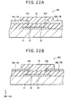
- FIG. 20 schematically shows a general constitution (Z-X sectional constitution) of a semiconductor element (thin film transistor 1E) according to a sixth embodiment. Unlike the thin film transistors 1 and 1A to 1D described thus far, this thin film transistor 1E is a bottom-contact staggered type organic TFT.
- the thin film transistor 1E is for example formed by laminating a gate electrode 12, a gate insulating film 13, a pair of source-drain electrodes 15A and 15B and an organic semiconductor layer 14 and a pair of wiring layers 17A and 17B in this order on a substrate 11.
- the source-drain electrodes 15A and 15B in contact with the organic semiconductor layer 14 are formed separately from the wiring layers 17A and 17B electrically connected to the source-drain electrodes 15A and 15B.
- the source-drain electrodes 15A and 15B in the thin film transistors 1 and 1A to 1D are on the organic semiconductor layer 14 and in contact with the organic semiconductor layer 14
- the source-drain electrodes 15A and 15B in the thin film transistor 1E are in a layer under the organic semiconductor layer 14 and in contact with the organic semiconductor layer 14.
- the source-drain electrodes 15A and 15B in the thin film transistor 1E are each formed by dropping and filling a constituent material (ink) for the source-drain electrodes 15A and 15B into the inside of a bank of a predetermined shape (the bank 19 or the bank 19A). Then, the organic semiconductor layer 14 in the thin film transistor 1E is formed on the source-drain electrodes 15A and 15B after removal of the above-described bank. That is, unlike the thin film transistor 1D, the bank is ultimately removed and does not remain in the thin film transistor 1E.
- the present disclosure is not limited to the case of forming the source-drain electrodes 15A and 15B thus using the bank, but the source-drain electrodes 15A and 15B may be formed without the use of the bank.
- FIGS. 21A to 21D are plan views (X-Y plan views) showing an example of main processes in a method of manufacturing the thin film transistor 1E according to the present embodiment in order of the processes.
- a gate electrode 12 and gate wiring 12L are formed on a substrate 11, and a gate insulating film 13 is formed on the gate electrode 12 and the gate wiring 12L.
- source-drain electrodes 15A and 15B are formed on the gate insulating film 13 by a printing process (ink jet printing) using a bank as described above, for example. Incidentally, when the source-drain electrodes 15A and 15B are thus formed by using the bank, the bank is thereafter removed.
- an organic semiconductor layer 14 in the shape of an island is formed on the gate insulating film 13 and the source-drain electrodes 15A and 15B by using a printing method such as flexography, for example.
- a printing method such as flexography
- an etching stopper layer 19B made of a fluorine base resin or the like is formed so as to cover the entire surface of the organic semiconductor layer 14 by a printing method such as a reverse offset printing method, for example.
- a wiring layer 170 is formed on the entire surface by using a sputtering method, for example, and for example a resist film 8 is pattern-printed into the shape of wiring layers 17A and 17B.
- a mixed acid of a nitric acid, a hydrofluoric acid, and a phosphoric acid for example, the wiring layer 170 is wet-etched, and thereafter the resist film 8 is dissolved and removed, whereby the wiring layers 17A and 17B are formed as shown in FIG. 21D .
- the thin film transistor 1E according to the present embodiment is completed.
- the source-drain electrodes 15A and 15B disposed on the organic semiconductor layer 14 so as to be in contact with the organic semiconductor layer 14 are formed separately from the wiring layers 17A and 17B electrically connected to the source-drain electrodes 15A and 15B.
- the source-drain electrodes 15A and 15B in contact with the organic semiconductor layer 14 are formed in a separate process from that of the wiring layers 17A and 17B electrically connected to the source-drain electrodes 15A and 15B.
- the present embodiment can thus reduce wiring resistance in the wiring layers 17A and 17B while suppressing contact resistance between the organic semiconductor layer 14 and the source-drain electrodes 15A and 15B as compared with a case where the source-drain electrodes 15A and 15B are formed integrally with (in a same process as) the wiring layers 17A and 17B, as will be described in the following, for example.
- the present embodiment can also improve reliability (reduce manufacturing defects).
- source-drain electrodes 15A and 15B functioning also as wiring layers 17A and 17B have a large film thickness, and therefore the wiring resistance of the source-drain electrodes 15A and 15B is lowered.
- source-drain electrodes 15A and 15B functioning also as wiring layers 17A and 17B have a small film thickness. Therefore, as compared with the foregoing fourth example of comparison, contact resistance at the level difference parts of the source-drain electrodes 15A and 15B is lowered, so that reliability is improved (manufacturing defects are reduced) in this respect.
- the small film thickness of the source-drain electrodes 15A and 15B functioning also as the wiring layers 17A and 17B means that wiring resistance is increased as compared with the foregoing fourth example of comparison. Thus, a problem in reliability may occur in this respect.
- the present embodiment enables the film thickness of the source-drain electrodes 15A and 15B separate from the wiring layers 17A and 17B to be reduced while enabling the film thickness of the wiring layers 17A and 17B to be increased.
- the present embodiment can reduce wiring resistance while suppressing contact resistance.
- FIGS. 23A and 23B schematically show a general constitution of a display device (display device 2) having the semiconductor element (thin film transistor 1 or 1A to 1E) according to each of the foregoing embodiments.
- FIG. 23B shows a planar constitution (X-Y planar constitution).
- FIG. 23A shows a sectional constitution (Z-X sectional constitution) taken along a line VI-VI in the direction of arrows in FIG. 23B .
- This display device 2 is formed by laminating a substrate 11, a TFT layer 22, a display layer 23, and a transparent substrate 24 in this order. Specifically, the TFT layer 22, the display layer 23, and the transparent substrate 24 are laminated on a display region 20A in the substrate 11, while the TFT layer 22, the display layer 23, and the transparent substrate 24 are not laminated on a frame region (non-display region) 20B in the substrate 11.
- the TFT layer 22 includes a plurality of devices including thin films (a conductive film such as a metallic film or the like, an insulating film, and the like).
- the devices include for example a TFT as a switching element for selecting a pixel as well as a capacitance element (a storage capacitor element and the like), wiring (a scanning line, a signal line, and the like), and electrodes (a pixel electrode and the like).
- the TFT in this case is formed by the thin film transistor (organic TFT) according to each of the foregoing embodiments using the organic semiconductor layer 14 as a channel layer.
- the display layer 23 includes electrophoretic particles, a liquid crystal layer, an organic EL (Electro Luminescence) layer, an inorganic EL layer, or the like between a pixel electrode and a common electrode, for example. That is, the display layer 23 is formed by using an electrophoretic element, a liquid crystal element, an organic EL element, an inorganic EL element, or the like.
- the pixel electrode is disposed in the TFT layer 22 in each pixel, and the common electrode is disposed over one surface of the transparent substrate 24.
- the transparent substrate 24 is for example formed by using a material similar to that of the substrate 11.
- a moisture preventing film for preventing the entry of water into the display layer 23 and an optically functional film for preventing a glare of extraneous light on a display surface may be further provided on the transparent substrate 24.
- This display device 2 is applicable to electronic devices in all fields such as television devices, digital cameras, notebook personal computers, portable terminal devices such as portable telephones and the like, video cameras, and the like. In other words, the display device 2 is applicable to electronic devices in all fields that display an externally input video signal or a video signal generated within the electronic devices as a still image or video.
- FIG. 24A and FIG. 24B each show an external appearance of an electronic book to which the display device 2 is applied.
- the electronic book has for example a display section 210 and a non-display section 220.
- the display section 210 is formed by the display device 2.
- FIG. 25 shows an external appearance of a television device to which the display device 2 is applied.
- This television device has for example a video display screen section 300 including a front panel 310 and a filter glass 320.
- the video display screen section 300 is formed by the display device 2.
- FIGS. 26A and 26B show an external appearance of a digital camera to which the display device 2 is applied.
- This digital camera has for example a light emitting section 410 for flashlight, a display section 420, a menu switch 430, and a shutter button 440.
- the display section 420 is formed by the display device 2.
- FIG. 27 shows an external appearance of a notebook personal computer to which the display device 2 is applied.
- This notebook personal computer has for example a main unit 510, a keyboard 520 for operations of inputting characters and the like, and a display section 530 for displaying an image.
- the display section 530 is formed by the display device 2.
- FIG. 28 shows an external appearance of a video camera to which the display device 2 is applied.
- This video camera has for example a main body section 610, a lens 620 for taking a subject, which lens is disposed in a front side surface of the main body section 610, a start/stop switch 630 at a time of picture taking, and a display section 640.
- the display section 640 is formed by the display device 2.
- FIGS. 29A to 29G show an external appearance of a portable telephone to which the display device 2 is applied.
- This portable telephone is for example formed by coupling an upper side casing 710 and a lower side casing 720 to each other by a coupling part (hinge part) 730.
- the portable telephone has a display 740, a sub-display 750, a picture light 760, and a camera 770. Of these parts, the display 740 or the sub-display 750 is formed by the display device 2.
- the materials and thicknesses or the film forming methods and film forming conditions or the like of the respective layers described in the foregoing embodiments and the like are not limited, but may be other materials and thicknesses or other film forming methods and film forming conditions.
- the foregoing embodiments and the like have been described by citing concrete constitutions of display devices, not all the layers need to be provided, and other layers may be further provided.
- a thin film transistor including an organic semiconductor layer, a gate electrode, a pair of source-drain electrodes, and a wiring layer
- organic TFT thin film transistor
- the present technology is applicable to other semiconductor elements such as diodes (rectifying elements) and the like including an organic semiconductor layer, a pair of electrodes (an anode electrode and a cathode electrode), and a wiring layer, for example.
- the present technology can also adopt the following constitutions.
Landscapes
- Engineering & Computer Science (AREA)
- Microelectronics & Electronic Packaging (AREA)
- Thin Film Transistor (AREA)
- Devices For Indicating Variable Information By Combining Individual Elements (AREA)
- Electroluminescent Light Sources (AREA)
- Electrodes Of Semiconductors (AREA)
Applications Claiming Priority (2)
| Application Number | Priority Date | Filing Date | Title |
|---|---|---|---|
| JP2011136492 | 2011-06-20 | ||
| JP2011279240A JP6035734B2 (ja) | 2011-06-20 | 2011-12-21 | 半導体素子、表示装置および電子機器 |
Publications (1)
| Publication Number | Publication Date |
|---|---|
| EP2538443A2 true EP2538443A2 (en) | 2012-12-26 |
Family
ID=46466117
Family Applications (1)
| Application Number | Title | Priority Date | Filing Date |
|---|---|---|---|
| EP12171717A Withdrawn EP2538443A2 (en) | 2011-06-20 | 2012-06-13 | Semiconductor element, method for manufacturing same, display device, and electronic device |
Country Status (6)
| Country | Link |
|---|---|
| US (1) | US8692255B2 (https=) |
| EP (1) | EP2538443A2 (https=) |
| JP (1) | JP6035734B2 (https=) |
| KR (1) | KR20120140201A (https=) |
| CN (1) | CN102842674A (https=) |
| TW (1) | TW201304223A (https=) |
Families Citing this family (10)
| Publication number | Priority date | Publication date | Assignee | Title |
|---|---|---|---|---|
| JP5830930B2 (ja) * | 2011-05-19 | 2015-12-09 | ソニー株式会社 | 半導体素子および電子機器 |
| CN104040614B (zh) * | 2012-07-11 | 2017-05-03 | Lg化学株式会社 | 用于形成显示基板的边框图案的方法 |
| CN104103696B (zh) * | 2013-04-15 | 2018-02-27 | 清华大学 | 双极性薄膜晶体管 |
| KR20150007000A (ko) | 2013-07-10 | 2015-01-20 | 삼성디스플레이 주식회사 | 박막 트랜지스터 기판 및 박막 트랜지스터 기판의 제조 방법 |
| JP2015041642A (ja) | 2013-08-20 | 2015-03-02 | ソニー株式会社 | 電子デバイス、画像表示装置、及び、画像表示装置を構成する基板 |
| JP6390122B2 (ja) * | 2014-03-10 | 2018-09-19 | 凸版印刷株式会社 | 薄膜トランジスタ、薄膜トランジスタアレイの製造方法及び画像表示装置 |
| CN104022124B (zh) * | 2014-05-26 | 2017-06-27 | 京东方科技集团股份有限公司 | 一种柔性显示基板及其制备方法、柔性显示装置 |
| US10217819B2 (en) * | 2015-05-20 | 2019-02-26 | Samsung Electronics Co., Ltd. | Semiconductor device including metal-2 dimensional material-semiconductor contact |
| CN105182590B (zh) * | 2015-10-10 | 2018-10-19 | 京东方科技集团股份有限公司 | 触摸显示面板及其制备方法以及显示装置 |
| KR102054190B1 (ko) * | 2017-01-23 | 2019-12-10 | 동우 화인켐 주식회사 | 고성능 필름형 터치 센서 및 그 제조방법 |
Citations (2)
| Publication number | Priority date | Publication date | Assignee | Title |
|---|---|---|---|---|
| JP2011136492A (ja) | 2009-12-28 | 2011-07-14 | Dainippon Printing Co Ltd | フィルム基材の接着方法 |
| JP2011179240A (ja) | 2010-03-02 | 2011-09-15 | Miwa Lock Co Ltd | 錠前 |
Family Cites Families (15)
| Publication number | Priority date | Publication date | Assignee | Title |
|---|---|---|---|---|
| JP2635885B2 (ja) * | 1992-06-09 | 1997-07-30 | インターナショナル・ビジネス・マシーンズ・コーポレイション | 薄膜トランジスタ及びアクティブマトリクス液晶表示装置 |
| JP4211250B2 (ja) * | 2000-10-12 | 2009-01-21 | セイコーエプソン株式会社 | トランジスタ及びそれを備える表示装置 |
| JP3787839B2 (ja) * | 2002-04-22 | 2006-06-21 | セイコーエプソン株式会社 | デバイスの製造方法、デバイス及び電子機器 |
| JP2005142474A (ja) * | 2003-11-10 | 2005-06-02 | Canon Inc | 電界効果型トランジスタおよびその製造方法 |
| JP4431081B2 (ja) * | 2004-08-30 | 2010-03-10 | エルジー ディスプレイ カンパニー リミテッド | 有機薄膜トランジスタの製造方法及び液晶表示素子の製造方法 |
| JP2006251120A (ja) * | 2005-03-09 | 2006-09-21 | Seiko Epson Corp | 画素構造、アクティブマトリクス基板、アクティブマトリクス基板の製造方法、電気光学装置、並びに電子機器 |
| JP4675730B2 (ja) * | 2005-09-08 | 2011-04-27 | シャープ株式会社 | 膜パターン形成用基板ならびに膜パターン形成基板、薄膜トランジスタ形成基板、液晶表示素子とその製造方法 |
| CN1996618A (zh) * | 2005-12-31 | 2007-07-11 | 财团法人工业技术研究院 | 薄膜晶体管 |
| KR101163791B1 (ko) * | 2006-05-16 | 2012-07-10 | 삼성전자주식회사 | 유기 전자소자의 전극형성 방법, 이에 의해 형성된 전극을포함하는 유기박막 트랜지스터 및 이를 포함하는 표시소자 |
| JP5194526B2 (ja) * | 2007-04-06 | 2013-05-08 | コニカミノルタホールディングス株式会社 | 薄膜トランジスタの製造方法、画素アレイの製造方法 |
| JP2010129742A (ja) * | 2008-11-27 | 2010-06-10 | Konica Minolta Holdings Inc | 電子デバイス及びその製造方法 |
| JP2010135378A (ja) * | 2008-12-02 | 2010-06-17 | Sony Corp | 半導体装置、半導体装置の製造方法、および電子機器 |
| JP5429454B2 (ja) * | 2009-04-17 | 2014-02-26 | ソニー株式会社 | 薄膜トランジスタの製造方法および薄膜トランジスタ |
| KR101470811B1 (ko) * | 2009-09-16 | 2014-12-09 | 가부시키가이샤 한도오따이 에네루기 켄큐쇼 | 반도체 장치 |
| JP5532803B2 (ja) * | 2009-09-30 | 2014-06-25 | ソニー株式会社 | 半導体デバイスおよび表示装置 |
-
2011
- 2011-12-21 JP JP2011279240A patent/JP6035734B2/ja not_active Expired - Fee Related
-
2012
- 2012-06-08 TW TW101120773A patent/TW201304223A/zh unknown
- 2012-06-12 KR KR1020120062795A patent/KR20120140201A/ko not_active Withdrawn
- 2012-06-13 US US13/495,820 patent/US8692255B2/en not_active Expired - Fee Related
- 2012-06-13 CN CN2012101961007A patent/CN102842674A/zh active Pending
- 2012-06-13 EP EP12171717A patent/EP2538443A2/en not_active Withdrawn
Patent Citations (2)
| Publication number | Priority date | Publication date | Assignee | Title |
|---|---|---|---|---|
| JP2011136492A (ja) | 2009-12-28 | 2011-07-14 | Dainippon Printing Co Ltd | フィルム基材の接着方法 |
| JP2011179240A (ja) | 2010-03-02 | 2011-09-15 | Miwa Lock Co Ltd | 錠前 |
Non-Patent Citations (1)
| Title |
|---|
| C. D. DIMITRAKOPOULOS; P. R. L. MALENFANT, ADV. MATER., vol. 14, no. 2, 2002, pages 99 |
Also Published As
| Publication number | Publication date |
|---|---|
| TW201304223A (zh) | 2013-01-16 |
| US20120319116A1 (en) | 2012-12-20 |
| US8692255B2 (en) | 2014-04-08 |
| JP6035734B2 (ja) | 2016-11-30 |
| KR20120140201A (ko) | 2012-12-28 |
| JP2013030730A (ja) | 2013-02-07 |
| CN102842674A (zh) | 2012-12-26 |
Similar Documents
| Publication | Publication Date | Title |
|---|---|---|
| US8692255B2 (en) | Semiconductor element, method for manufacturing same, display device, and electronic device | |
| KR20190053164A (ko) | 반도체 소자 및 전자 장치 | |
| CN111509011A (zh) | 显示装置及其制备方法 | |
| JP2008270744A (ja) | 薄膜トランジスタアレイ、薄膜トランジスタアレイの製造方法、およびアクティブマトリスクディスプレイ | |
| US20200075773A1 (en) | Thin film transistor, method of manufacturing thin film transistor, array substrate and display panel | |
| EP3066692A1 (en) | Self-aligned metal oxide tft | |
| JP5835221B2 (ja) | 薄膜トランジスタ及びその製造方法、並びに画像表示装置 | |
| TW201316581A (zh) | 有機薄膜電晶體,其製造方法,以及顯示器 | |
| US11625132B2 (en) | Touch pad and method for manufacturing the same, touch display device | |
| JP5655421B2 (ja) | 半導体装置、表示装置、および電子機器 | |
| EP4521466A1 (en) | Array substrate, manufacturing method therefor, and display apparatus | |
| CN102376893A (zh) | 半导体装置、显示装置和电子装置 | |
| US9401486B2 (en) | Driving circuit board, method of manufacturing the same, display unit, and electronic apparatus | |
| JP5700291B2 (ja) | 薄膜トランジスタとその製造方法、および当該薄膜トランジスタを用いた画像表示装置 | |
| JP2010135584A (ja) | 薄膜トランジスタ、薄膜トランジスタの製造方法、表示装置、および電子機器 | |
| JP2013201201A (ja) | 薄膜トランジスタアレイ、薄膜トランジスタアレイ製造方法、画像表示装置 | |
| US10707313B2 (en) | Thin film transistor, method of manufacturing thin film transistor, and display | |
| WO2013146035A1 (ja) | 半導体装置およびその製造方法、表示装置ならびに電子機器 | |
| KR20120129771A (ko) | 반도체 소자 및 전자 장치 | |
| JP2010134362A (ja) | 薄膜トランジスタアレイ及びその製造方法 | |
| EP4672937A1 (en) | DISPLAY SUBSTRATE AND ITS PREPARATION PROCESS, AND DISPLAY DEVICE | |
| WO2014155998A1 (ja) | 薄膜トランジスタアレイおよび画像表示装置 | |
| JP2014056850A (ja) | トランジスタおよびその製造方法、並びに半導体装置の製造方法および表示装置の製造方法 |
Legal Events
| Date | Code | Title | Description |
|---|---|---|---|
| PUAI | Public reference made under article 153(3) epc to a published international application that has entered the european phase |
Free format text: ORIGINAL CODE: 0009012 |
|
| 17P | Request for examination filed |
Effective date: 20120615 |
|
| AK | Designated contracting states |
Kind code of ref document: A2 Designated state(s): AL AT BE BG CH CY CZ DE DK EE ES FI FR GB GR HR HU IE IS IT LI LT LU LV MC MK MT NL NO PL PT RO RS SE SI SK SM TR |
|
| AX | Request for extension of the european patent |
Extension state: BA ME |
|
| STAA | Information on the status of an ep patent application or granted ep patent |
Free format text: STATUS: THE APPLICATION HAS BEEN WITHDRAWN |
|
| 18W | Application withdrawn |
Effective date: 20130430 |