EP2537651A1 - Procédé et dispositif de coupe d'un tronçon d'aliments en tranches - Google Patents
Procédé et dispositif de coupe d'un tronçon d'aliments en tranches Download PDFInfo
- Publication number
- EP2537651A1 EP2537651A1 EP20120172126 EP12172126A EP2537651A1 EP 2537651 A1 EP2537651 A1 EP 2537651A1 EP 20120172126 EP20120172126 EP 20120172126 EP 12172126 A EP12172126 A EP 12172126A EP 2537651 A1 EP2537651 A1 EP 2537651A1
- Authority
- EP
- European Patent Office
- Prior art keywords
- food
- feed
- food strand
- fixing
- strand
- Prior art date
- Legal status (The legal status is an assumption and is not a legal conclusion. Google has not performed a legal analysis and makes no representation as to the accuracy of the status listed.)
- Granted
Links
Images


Classifications
-
- B—PERFORMING OPERATIONS; TRANSPORTING
- B26—HAND CUTTING TOOLS; CUTTING; SEVERING
- B26D—CUTTING; DETAILS COMMON TO MACHINES FOR PERFORATING, PUNCHING, CUTTING-OUT, STAMPING-OUT OR SEVERING
- B26D7/00—Details of apparatus for cutting, cutting-out, stamping-out, punching, perforating, or severing by means other than cutting
- B26D7/01—Means for holding or positioning work
- B26D7/02—Means for holding or positioning work with clamping means
-
- B—PERFORMING OPERATIONS; TRANSPORTING
- B26—HAND CUTTING TOOLS; CUTTING; SEVERING
- B26D—CUTTING; DETAILS COMMON TO MACHINES FOR PERFORATING, PUNCHING, CUTTING-OUT, STAMPING-OUT OR SEVERING
- B26D7/00—Details of apparatus for cutting, cutting-out, stamping-out, punching, perforating, or severing by means other than cutting
- B26D7/01—Means for holding or positioning work
-
- B—PERFORMING OPERATIONS; TRANSPORTING
- B26—HAND CUTTING TOOLS; CUTTING; SEVERING
- B26D—CUTTING; DETAILS COMMON TO MACHINES FOR PERFORATING, PUNCHING, CUTTING-OUT, STAMPING-OUT OR SEVERING
- B26D7/00—Details of apparatus for cutting, cutting-out, stamping-out, punching, perforating, or severing by means other than cutting
- B26D7/06—Arrangements for feeding or delivering work of other than sheet, web, or filamentary form
- B26D7/0608—Arrangements for feeding or delivering work of other than sheet, web, or filamentary form by pushers
-
- B—PERFORMING OPERATIONS; TRANSPORTING
- B26—HAND CUTTING TOOLS; CUTTING; SEVERING
- B26D—CUTTING; DETAILS COMMON TO MACHINES FOR PERFORATING, PUNCHING, CUTTING-OUT, STAMPING-OUT OR SEVERING
- B26D7/00—Details of apparatus for cutting, cutting-out, stamping-out, punching, perforating, or severing by means other than cutting
- B26D7/06—Arrangements for feeding or delivering work of other than sheet, web, or filamentary form
- B26D7/0616—Arrangements for feeding or delivering work of other than sheet, web, or filamentary form by carriages, e.g. for slicing machines
-
- B—PERFORMING OPERATIONS; TRANSPORTING
- B26—HAND CUTTING TOOLS; CUTTING; SEVERING
- B26D—CUTTING; DETAILS COMMON TO MACHINES FOR PERFORATING, PUNCHING, CUTTING-OUT, STAMPING-OUT OR SEVERING
- B26D7/00—Details of apparatus for cutting, cutting-out, stamping-out, punching, perforating, or severing by means other than cutting
- B26D7/06—Arrangements for feeding or delivering work of other than sheet, web, or filamentary form
- B26D7/0641—Arrangements for feeding or delivering work of other than sheet, web, or filamentary form using chutes, hoppers, magazines
-
- B—PERFORMING OPERATIONS; TRANSPORTING
- B26—HAND CUTTING TOOLS; CUTTING; SEVERING
- B26D—CUTTING; DETAILS COMMON TO MACHINES FOR PERFORATING, PUNCHING, CUTTING-OUT, STAMPING-OUT OR SEVERING
- B26D7/00—Details of apparatus for cutting, cutting-out, stamping-out, punching, perforating, or severing by means other than cutting
- B26D7/01—Means for holding or positioning work
- B26D2007/013—Means for holding or positioning work the work being tubes, rods or logs
-
- B—PERFORMING OPERATIONS; TRANSPORTING
- B26—HAND CUTTING TOOLS; CUTTING; SEVERING
- B26D—CUTTING; DETAILS COMMON TO MACHINES FOR PERFORATING, PUNCHING, CUTTING-OUT, STAMPING-OUT OR SEVERING
- B26D2210/00—Machines or methods used for cutting special materials
- B26D2210/02—Machines or methods used for cutting special materials for cutting food products, e.g. food slicers
-
- B—PERFORMING OPERATIONS; TRANSPORTING
- B26—HAND CUTTING TOOLS; CUTTING; SEVERING
- B26D—CUTTING; DETAILS COMMON TO MACHINES FOR PERFORATING, PUNCHING, CUTTING-OUT, STAMPING-OUT OR SEVERING
- B26D7/00—Details of apparatus for cutting, cutting-out, stamping-out, punching, perforating, or severing by means other than cutting
- B26D7/06—Arrangements for feeding or delivering work of other than sheet, web, or filamentary form
- B26D7/0683—Arrangements for feeding or delivering work of other than sheet, web, or filamentary form specially adapted for elongated articles
-
- Y—GENERAL TAGGING OF NEW TECHNOLOGICAL DEVELOPMENTS; GENERAL TAGGING OF CROSS-SECTIONAL TECHNOLOGIES SPANNING OVER SEVERAL SECTIONS OF THE IPC; TECHNICAL SUBJECTS COVERED BY FORMER USPC CROSS-REFERENCE ART COLLECTIONS [XRACs] AND DIGESTS
- Y10—TECHNICAL SUBJECTS COVERED BY FORMER USPC
- Y10T—TECHNICAL SUBJECTS COVERED BY FORMER US CLASSIFICATION
- Y10T83/00—Cutting
- Y10T83/04—Processes
-
- Y—GENERAL TAGGING OF NEW TECHNOLOGICAL DEVELOPMENTS; GENERAL TAGGING OF CROSS-SECTIONAL TECHNOLOGIES SPANNING OVER SEVERAL SECTIONS OF THE IPC; TECHNICAL SUBJECTS COVERED BY FORMER USPC CROSS-REFERENCE ART COLLECTIONS [XRACs] AND DIGESTS
- Y10—TECHNICAL SUBJECTS COVERED BY FORMER USPC
- Y10T—TECHNICAL SUBJECTS COVERED BY FORMER US CLASSIFICATION
- Y10T83/00—Cutting
- Y10T83/647—With means to convey work relative to tool station
- Y10T83/654—With work-constraining means on work conveyor [i.e., "work-carrier"]
- Y10T83/6563—With means to orient or position work carrier relative to tool station
Definitions
- high-performance slicer which are used in the industrial production and processing of meat and sausage products and cheese use.
- high-performance slicers typically, in such high-performance slicers, several food racks are placed parallel to one another, conveyed and cut, with a correspondingly large-sized slicing knife sweeping over the cross-sections of all juxtaposed food racks and thus separating a corresponding plurality of slices from the food racks at each revolution.
- the food strands are placed in parallel arrangement on an arranged as a feed belt and arranged for the most part outside of a machine housing feeder by an operator. Then, the food strands are simultaneously promoted by the feed belt on the feed device, which has a number of concurrently handled food strands corresponding number of narrow, in cross-section V-shaped feed belts. After a complete transfer of the food strands on the conveyor belts of the feed device, this can be transferred by a pivoting movement, for example, 75 ° in the actual feed position.
- a cutting device with such a holding unit is for example the DE 195 18 583 A1 removable.
- This shows a so-called collet holder, which is able to intervene with a plurality of juxtaposed food strands from the rear side thereof and then fed controlled to the knife of the cutter.
- the collet holder engages the food strings as soon as they are in their feed position, that is, they are arranged inclined relative to the horizontal axis.
- the former can be guided by means of guide means, wherein in particular both side surfaces and an upper side of a respective food strand can be fixed, while the underside rests on the respective conveyor belt.
- Another device which uses the principle of pivoting a plurality of food strands against the horizontal, is in the EP 2 239 108 A2 shown.
- the individual food strands are pivoted by means of a separate device against the horizontal and then - pushed out of the pivoted position - on a permanently "obliquely" set feed belt or pulled.
- the individual food strands are separated by means of rigid partitions and thus blocked against lateral breaking or buckling.
- a disadvantage occurs in the known procedure in appearance that despite the orientation of the food strands at their front ends a precisely aligned alignment of the same at their backs, ie rear ends, not always succeed. This is because that the food strands are inevitably subject to a certain length tolerance in their production, which manifest themselves in steps or paragraphs on the back of parallel juxtaposed food strands. This in turn means that for holding devices with hook-shaped gripping elements, which dig into the material of the food strand, for safety reasons an intervention must be set farther away from the end of the food strand to close engagement at the food strand end and thus a reduction of the maximum It is essential to avoid holding power.
- the underlying object is achieved in that the food strand fixed at least during the transfer from the transfer position to the feed position on at least one of its longitudinal sides, preferably at least one of its free longitudinal sides, by means of at least one fixing a fixing is, wherein the at least one fixing element forms a positive connection and / or a frictional connection with the food strand.
- the inventive fixation of the food strand avoids that the food strand during or after the transfer into the more inclined feed position slides forward and therefore - as in the prior art, the case - must be aligned aligned on its front.
- the form-fit or adhesion with the food strands formed by means of the at least one fixing element is able to The typically due to the skewing of the food strands on self-acting weight forces that would have the undesirable "slippage" result, record and remove.
- the fixing device thus makes it possible to keep the food strand during and after the transfer to the more inclined feed position in the previously assumed position - relative to the feed device - considered.
- the method according to the invention accordingly enables the food strand to be aligned even before it is transferred to the feed position or provides the possibility of maintaining an orientation made prior to the transfer to the advancing position even after the aforementioned transfer.
- the alignment of the rear ends of the food strands allows only the use of so-called vacuum grippers as a holding device because - unlike gripper hooks - there is the setting of a "security surcharge" with respect to the coupling point is not possible, at least if the vacuum gripper also off are connected to a block and combined with a common traversing drive in the feed direction suction cups are combined, which is imperative from economic aspects in comparison with an individual movement and control of each individual suction head.
- the food strand is contacted on two opposite longitudinal sides by a fixing element of the fixing device, preferably by exerting a clamping force on an outer casing of the food strand by means of two opposing clamping jaws of the fixing device.
- Jaws as fixing cause a frictional connection with the food strands. The safety in fixing is increased by such a procedure in comparison with a one-sided attack of the fixing force.
- An embodiment of the invention further provides that the food strand is fixed in a one-third of its length facing a rear end, while it is transferred from the transfer position to the feed position.
- a development of the method according to the invention consists in this respect in that the food strand is fixed by the fixing device and actively conveyed, preferably pulled, while it is being moved from the insertion position into the transfer position and / or while it is moving from the advancing position in the direction of the cutting device to be moved.
- the fixing device can thus advantageously also be used as a conveyor during two phases of the process sequence according to the invention.
- the fixing device for this purpose must have suitable drive means which are able to move the at least one fixing element relative to the feed device.
- the procedure described under point a) has the advantage that the slicing process of a new food strand can already be started at a time when the holding device has returned to its starting position after the slicing process at the preceding food strand has ended. It is therefore not necessary to bring the holding device into contact with the rear end of the new Gutsstrangs, which according to the invention even with already running feed movement, i. while the cutting operation is running. In the aforementioned manner can thus be realized a further increase in performance.
- the procedure according to point b) means a particularly high process reliability, since the food strand is fixed in this typically a middle phase of the slicing process performing phase both of the fixing device as well as held by the holding device. In the middle phase of the slicing process, such a "double-fixation" is without detriment to the cutting performance, as there will be enough time later to provide a new batch of food racks for the slicing process, again requiring the fixing device.
- the advantage can be achieved that the fixing device and in particular the feed device, to which the fixing device is coupled, during the slicing with a remaining strand length of less than about 200 mm to 300 mm for a safe process management is no longer needed. Rather, the leadership of the food strand is typically in this case by each ensures a lower and upper tractor belt in conjunction with the holding device. To increase performance, it is therefore expedient to transfer the feed device and the fixing device connected thereto already back to the transfer position in order to begin with the next loading process can.
- the underlying object is achieved in device-technical terms by a fixing with at least one fixing, with the food strand at least during the transfer of the transfer position in the feed position on at least one of its longitudinal sides, preferably at least one of its free longitudinal sides, can be fixed, wherein the at least one fixing element with the food strand forms a positive connection and / or a frictional connection.
- the fixing device allows an aligned alignment of a plurality of Gutsstrlinden at - viewed in the feed direction - rear ends, without such an orientation would be jeopardized by the transfer of the feed device in the more inclined feed position.
- On a locking device to achieve an alignment at the front ends can be completely dispensed with, which in turn reduces the equipment cost, since the adjustment of the lower tractor belt is no longer needed in a blocking position.
- a development of the device according to the invention is that the feed device is pivotable together with the fixing device relative to a machine frame about an axis which is perpendicular to the feed direction as well as to a direction of movement of the food strand in its transfer from the insertion position into the transfer position ,
- the fixing elements are designed as clamping jaws which can be pressed by means of a clamping drive from opposite sides to free longitudinal sides of the food strand and can be removed again from the longitudinal sides.
- a contact surface of at least one clamping jaw has a surface condition increasing the direction and / or effecting (micro) positive locking.
- the lower longitudinal side, on which the food strand is stored not as a free longitudinal side, but only the two opposite vertical longitudinal sides and the horizontal upper longitudinal side are to be regarded as "free longitudinal side".
- free longitudinal side For food carriers whose cross-section is not approximately angular, but round or oval, corresponding curved surface portions of the outer shell of the food strand are to be understood as "long sides" in the context of the present invention.
- the fixing elements are arranged on a fixing carriage, which is connected by means of a carriage drive, preferably via at least one timing belt, in the feed direction of the food strand relative to the feed device and further preferably connected thereto via a linear guide.
- the jaws are divided into a first group and a second group, wherein the jaws each contact a group of food strands from the same longitudinal side and wherein the jaws of the first group at a first Querhub bain and the jaws of the second group are arranged on a second transverse stroke carriage.
- the transverse lifting carriages can be movable relative to the fixing carriage, perpendicular to the longitudinal axes of the food racks and in each case in the opposite direction.
- a stop element arranged on the feed device which is preferably designed as a conveyor belt, in particular a stop bar, can be used, with which the food racks can be aligned with one another at their rear ends.
- the feed device for each food strand a guide element, preferably a guide rail, along which the respective food strand during the promotion of the loading device to the feed device and during the advancing movement, preferably slidably, is feasible.
- a waiver of an actively moving surface of the guide elements or guide rails is possible by the use of actively movable fixing elements, which act as preferentially pulling used funding when relative to the feed device, d. H. to the guide elements, to be moved.
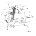
- FIG. 1 shown device for simultaneous cutting of six food strands 40 in slices has a set up on the ground machine frame 2, a feeder 3 in the form of a feed belt, a feed device 4, a fixing device 5, a holding device 6 and a cutting device 7, in FIG. 1 due to a cover not visible, the spiral cutting blade 8, however, in the Figures 5.1 to 5.8 is shown.
- the feed device 4 and the fixing device 5 together form a loading arm 9, the FIG. 2 is shown separately.
- the device 1 has three mutually parallel within the same plane extending upper tractor belt 10 (a tractor belt 10 for each two adjacent food trains 40) and six parallel to each other within the same plane extending lower tractor belt 11, wherein the in FIG. 1 not shown food strands 40 during the feed to the cutter 7 to each between two tractor belts 10, 11, which act with appropriate pressure on opposite free upper and lower longitudinal sides of the food strands 40 and thus a secure guidance of the food strands on the way to the cutting device. 7 towards and in particular in the last feed section in front of the cutting device 7 effect. For clarity, is in FIG.
- FIG. 1 a machine housing not shown, which in particular the area of the device 1, in which the loading rocker 9 and the cutting device 7 are, inaccessible for reasons of accident prevention encapsulates.
- a portal member 12 which is equipped with a pivotable closure flap 13, which releases a feed opening in its open position or closes in its closed position, thus preventing a Hereinglomi.
- FIG. 1 the loading arm 9 is shown in a feed position in which it is inclined relative to a horizontal by an angle of 75 °.
- the food strands 40 located on the advancing device 4 are held and / or fixed by the holding device 6 and fed forward by the fixing device 5 in the feed direction (arrow 14) to the cutting direction 7.
- the fixation by means of the fixing device 5 is achieved in the example shown by means of a frictional connection between the fixing device 5 and the food strands 40.
- the loading rocker 9 is pivotally mounted about an axis 15 so that it starts from the in FIG. 1 shown feed position in the direction of the arrow 16 is pivotable in a transfer position, in which they in the Figures 5.1 to 5.5 is shown.
- FIG. 1 also shows a control panel 18 in touch screen design, can be set with the different parameters of the device 1 for the cutting operation.
- the device 1 still has a non-illustrated conveyor belt, can be collected with the detached from the holding device 6 residual pieces after completion of a cutting cycle and conveyed into a container 20. Die philosophicalvorraum ist in Fig. 2 contradict.
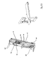
- FIG. 2 shows in an enlarged view the loading arm 9, which includes both the feed device 4 and the fixing device 5.
- the feed device 4 is in turn constructed of six mutually parallel guide rails 21 which are fixed to a common swing frame 22, which is composed, inter alia, of two longitudinal guide rods 23 and two end cross members 24.
- the swing frame 22 is a total, ie with the guide rails 21 and the entire fixing device 5, about a non-visible axis pivotally mounted in the machine frame (s. Fig. 1 ) stored.
- the drive for the pivoting movement of the loading arm 9 takes place by means of a pivotally coupled to a pivotable drive shaft pivot lever, at the end of a rotatably mounted roller is arranged, which cooperates with a backdrop-like guide on the underside of the swing frame 22 and so the lever pivoting in a pivoting movement of the loading arm 9 implements.
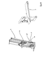
- the fixing device 5 consists of a in FIG. 3 Fixing slide 25 shown in detail, which is slidably mounted with its arranged at opposite ends bearing elements 26 on the guide rods 23 of the swing frame 22.
- the drive of the fixing carriage 25 takes place with the aid of two timing belts 27, which are each arranged between one of the guide rods 22 and the adjacent outer guide rail 21.
- Each timing belt 27 is connected in the region of its upper run in a located in the respective bearing element 26 connecting portion in force transmitting manner with the fixing carriage 25. Between the lower run and the bearing element 26 is a non-contact, ie friction-free, relative movement possible.
- the structure of the fixing slide 25 can be particularly well the representation in FIG. 3 From the fixing carriage 25, two transverse lifting carriages 30 and 31 are displaceably mounted in the direction of a double arrow 32.
- the relevant linear guides are in FIG. 3 not shown.
- At the transverse lift carriage 30 six jaws, which act as fixing elements 33, attached.
- six six fixing elements 34 also designed as clamping jaws, are fastened to the transverse lifting carriage 31.
- the one transverse lifting slide 30 is moved by means of a special pneumatic cylinder 17 arranged in one of the bearing elements 26 in one direction and the other transverse lifting slide 31 by means of the same pneumatic cylinder 17 in the other direction, they move alternately into two groups on the respective transverse lifting carriage 30, 31 fixed fixing elements 33, 34 in pairs either towards or away from each other.
- a Aufrationzumosine food strands 40 which are each located between two adjacent fixing elements 33 on the guide rails 21 arranged there, either clamped or released.
- the guide rails 21 are in FIG. 3 for reasons of clarity not shown in FIG. 2 However, in its course between each adjacent fixing elements 33, 34 located.
- the holding device 6 of six mutually parallel and in each case a guide rail 21 of the feed device 4, that is, in each case two fixing elements 33, 34 of the fixing device 5 associated holding elements 35, is composed.
- Each holding element 35 is designed in the form of a known gripping device with gripper hooks penetrating in pairs from opposite sides in the respective food strand 40. While the gripper hooks 36 of the holding elements 35 each enter from the associated rear end of each food strand 40, the fixing elements 33, 34 of the fixing device 5 engage from opposite free longitudinal sides of the food strands 40 in a clamping manner, ie to generate a frictional force.
- adjusting cylinders 37 of the upper tractor belt 10 are also shown, which serve to press the upper tractor belt 10 always with the required contact pressure against the upper longitudinal side of the respective food strand 40, so as to produce a good traction during the advancing movement.
- FIG 5.1 are located on the feeder 3 six food strands 40 in shape in their consistency soft Mettorulste, each having a length of about 1200 mm.
- the food strands 40 are each aligned with their rear end with the aid of a fixed to a conveyor belt of the feeder 3 stop member 41 aligned.
- the parallel alignment of the individual food strands 40 to one another can be facilitated by using an insertion aid arranged above the conveyor belt of the feed device 3.
- the closure flap 13 of the portal element 12 of the machine housing is closed, so that an operator can not inadvertently engage in the region of the loading bow 9.
- the loading rocker 9 is in the transfer position, in which it waits for the transfer of the food strands 40 through the feeder 3.
- the three upper tractor belts 10, the spiral cutting blade 8 (direction of rotation according to arrow 42) of the cutting device 7 and the holding elements 35 of the holding device 6 are shown.
- the summarized into a contiguous block holding elements 35 are connected via a cross-beam 44 with a guide carriage 43 of the holding device 6, wherein the guide carriage 43 along two guide rods 45 is linearly displaceable.
- the orientation of the guide rods 45 is 75 ° to a horizontal plane.
- the orientations of the guide rods 45 and thus the holding device 6 relative to the machine frame 2 is not changeable.
- the Guide rods 45 and also the longitudinal axes of the food strands 40 during the feed are aligned parallel to a rotation axis of the cutting space 8, ie perpendicular to a knife plane.
- Figure 5.3 shows a situation in which the food strands 40 with a part of their length are already located on the advancing device 4, wherein the front ends 46 of the food strands 40 already extend beyond the fixing carriage 25 of the fixing device 6 also. In this position, the food strands 40, the fixing elements 33, 34 thus come into action and each clamp a food strand 40 in the vicinity of the front end 46 between them. Meanwhile, the cutting process of the food strands 40 of the previous feed continues.
- FIG 5.4 is shown a situation in which the food strands 40 is almost completely transferred to the approximately horizontal position (transfer position) located loading arm 9.
- the fixing carriage 25 of the fixing device 6 has moved by activating a non-visible carriage drive correspondingly far in the direction of its front end position and thereby pulled the food strands 40 on the guide rails 21 of the feed device 4, wherein the conveyor belt of the feeder 3, also with the aid the strip-shaped stop element 41, the food strands has pushed behind at their rear ends 47 slightly.
- the loading rocker 9 is now from the waiting position to the differential angle 48 further pivoted from 15 ° in the feed position. Subsequently, the food strands 40 are moved to the cutting blade 8 of the cutting device 7 by starting the carriage drive, ie corresponding displacement of the fixing carriage 25.
- Figure 5.7 shows in this context a situation in which the food strands 40 are located with their front portions between the upper tractor belts 10 and the lower tractor belts 11 and are otherwise fixed only by the fixing device 5.
- the cutting process is already started in this situation, without waiting for the holding device 6 to move down to the rear ends 47 of the food racks 40 and grab and hold the food ropes 40 there.
- time can be saved and as much as the performance of the device 1 can be increased without the lack of rear support of the food racks 40 in the initial phase of the cutting process.
Applications Claiming Priority (1)
| Application Number | Priority Date | Filing Date | Title |
|---|---|---|---|
| DE201110051210 DE102011051210A1 (de) | 2011-06-20 | 2011-06-20 | Verfahren und Vorrichtung zum Schneiden eines Lebensmittelstrangs in Scheiben |
Publications (2)
| Publication Number | Publication Date |
|---|---|
| EP2537651A1 true EP2537651A1 (fr) | 2012-12-26 |
| EP2537651B1 EP2537651B1 (fr) | 2015-10-21 |
Family
ID=46354019
Family Applications (1)
| Application Number | Title | Priority Date | Filing Date |
|---|---|---|---|
| EP12172126.0A Not-in-force EP2537651B1 (fr) | 2011-06-20 | 2012-06-15 | Procédé et dispositif de coupe d'un tronçon d'aliments en tranches |
Country Status (7)
| Country | Link |
|---|---|
| US (1) | US9061432B2 (fr) |
| EP (1) | EP2537651B1 (fr) |
| CN (1) | CN102941595B (fr) |
| DE (1) | DE102011051210A1 (fr) |
| DK (1) | DK2537651T3 (fr) |
| ES (1) | ES2555996T3 (fr) |
| HK (1) | HK1182054A1 (fr) |
Cited By (6)
| Publication number | Priority date | Publication date | Assignee | Title |
|---|---|---|---|---|
| DE102015110533A1 (de) * | 2015-06-30 | 2017-01-05 | Weber Maschinenbau Gmbh Breidenbach | Zuführvorrichtung |
| EP3140091A4 (fr) * | 2014-05-07 | 2018-07-18 | Formax, Inc. | Appareil et procédés de tranchage de produit alimentaire |
| US10245745B2 (en) | 2016-04-28 | 2019-04-02 | TVI Entwicklung & Produktion GmbH | Slicing machine and method for slicing elastic strands in particular meat strands |
| DE102017123058A1 (de) | 2017-10-05 | 2019-04-11 | Tpv Gmbh | Verfahren zum Aufschneiden eines Lebensmittelstrangs sowie Schneidvorrichtung |
| EP3944937A1 (fr) * | 2020-07-29 | 2022-02-02 | Weber Maschinenbau GmbH Breidenbach | Découpeuse pour des alliments avec appareil de charge |
| EP3170632B1 (fr) * | 2015-10-26 | 2024-01-17 | Textor Maschinenbau GmbH | Dispositif et procédé destinés au découpage de produits alimentaires |
Families Citing this family (7)
| Publication number | Priority date | Publication date | Assignee | Title |
|---|---|---|---|---|
| DE102014112800A1 (de) * | 2014-09-05 | 2016-03-10 | Weber Maschinenbau Gmbh Breidenbach | Aufschneidevorrichtung |
| DE102017121799A1 (de) * | 2017-08-18 | 2019-02-21 | Weber Maschinenbau Gmbh Breidenbach | Produktzufuhr für eine vorrichtung zum aufschneiden von lebensmittelprodukten |
| CN108058208B (zh) * | 2018-01-22 | 2023-12-08 | 林志明 | 一种切条机 |
| CN108393950A (zh) * | 2018-03-09 | 2018-08-14 | 潍坊田汇食品有限公司 | 一种鸭翅切割机 |
| CN111844205A (zh) * | 2020-07-29 | 2020-10-30 | 陈余超 | 一种棍状中药材切片设备用送料装置 |
| CN112123416B (zh) * | 2020-08-04 | 2022-09-23 | 安徽抱香树生物科技有限公司 | 一种大量加工腊肠果用切割打包一体机 |
| CN112171732A (zh) * | 2020-08-27 | 2021-01-05 | 朱波云 | 一种药材切片装置 |
Citations (6)
| Publication number | Priority date | Publication date | Assignee | Title |
|---|---|---|---|---|
| DE19518583A1 (de) * | 1995-05-20 | 1996-11-21 | Schindler & Wagner Kg | Schneidmaschine |
| WO2000059689A1 (fr) * | 1999-03-31 | 2000-10-12 | Prima Meat Packers, Ltd. | Dispositif servant a trancher un produit alimentaire tel que du jambon |
| DE10353114A1 (de) * | 2003-10-15 | 2005-05-12 | Cfs Kempten Gmbh | Verfahren und Vorrichtung zum Aufschneiden von Lebensmittelriegeln |
| DE102007063112A1 (de) * | 2007-12-23 | 2009-07-23 | Dipl.-Ing. Schindler & Wagner Gmbh & Co. Kg | Schneidmaschine |
| DE102008020246A1 (de) * | 2008-04-22 | 2009-11-12 | Maschinenbau Heinrich Hajek Gmbh & Co. | Verfahren zur Beladung einer Hochgeschwindigkeits-Schneidmaschine mit Produkten und Beladungseinrichtung hierfür |
| EP2239108A2 (fr) * | 2007-10-22 | 2010-10-13 | Formax, Inc. | Machine de découpe d'aliments dotée d'un mécanisme de rétraction de lame de tranchage |
Family Cites Families (4)
| Publication number | Priority date | Publication date | Assignee | Title |
|---|---|---|---|---|
| CA2377198A1 (fr) * | 2001-03-23 | 2002-09-23 | Kraft Foods Holdings, Inc. | Methode et systeme automatises d'insertion de piles d'aliments tranches dans des emballages |
| US20070214969A1 (en) * | 2003-10-15 | 2007-09-20 | Peter Mueller | Method and Device for Slicing Food Bars |
| DE10353527A1 (de) * | 2003-11-14 | 2005-06-23 | Cfs Kempten Gmbh | Aufschneidevorrichtung mit einer krümmbaren Beladeschwinge |
| US7603936B2 (en) * | 2005-03-05 | 2009-10-20 | Formax, Inc. | Loaf seam synchronization device for continuous loaf feed slicing machine |
-
2011
- 2011-06-20 DE DE201110051210 patent/DE102011051210A1/de not_active Withdrawn
-
2012
- 2012-06-15 DK DK12172126.0T patent/DK2537651T3/en active
- 2012-06-15 ES ES12172126.0T patent/ES2555996T3/es active Active
- 2012-06-15 EP EP12172126.0A patent/EP2537651B1/fr not_active Not-in-force
- 2012-06-19 US US13/526,619 patent/US9061432B2/en not_active Expired - Fee Related
- 2012-06-20 CN CN201210402264.0A patent/CN102941595B/zh not_active Expired - Fee Related
-
2013
- 2013-08-13 HK HK13109434.0A patent/HK1182054A1/zh not_active IP Right Cessation
Patent Citations (6)
| Publication number | Priority date | Publication date | Assignee | Title |
|---|---|---|---|---|
| DE19518583A1 (de) * | 1995-05-20 | 1996-11-21 | Schindler & Wagner Kg | Schneidmaschine |
| WO2000059689A1 (fr) * | 1999-03-31 | 2000-10-12 | Prima Meat Packers, Ltd. | Dispositif servant a trancher un produit alimentaire tel que du jambon |
| DE10353114A1 (de) * | 2003-10-15 | 2005-05-12 | Cfs Kempten Gmbh | Verfahren und Vorrichtung zum Aufschneiden von Lebensmittelriegeln |
| EP2239108A2 (fr) * | 2007-10-22 | 2010-10-13 | Formax, Inc. | Machine de découpe d'aliments dotée d'un mécanisme de rétraction de lame de tranchage |
| DE102007063112A1 (de) * | 2007-12-23 | 2009-07-23 | Dipl.-Ing. Schindler & Wagner Gmbh & Co. Kg | Schneidmaschine |
| DE102008020246A1 (de) * | 2008-04-22 | 2009-11-12 | Maschinenbau Heinrich Hajek Gmbh & Co. | Verfahren zur Beladung einer Hochgeschwindigkeits-Schneidmaschine mit Produkten und Beladungseinrichtung hierfür |
Cited By (13)
| Publication number | Priority date | Publication date | Assignee | Title |
|---|---|---|---|---|
| EP3140091A4 (fr) * | 2014-05-07 | 2018-07-18 | Formax, Inc. | Appareil et procédés de tranchage de produit alimentaire |
| US10919170B2 (en) | 2014-05-07 | 2021-02-16 | Provisur Technologies, Inc. | Food product slicing apparatus |
| EP3140091B1 (fr) | 2014-05-07 | 2021-04-07 | Formax, Inc. | Appareil de tranchage de produit alimentaire |
| DE102015110533A1 (de) * | 2015-06-30 | 2017-01-05 | Weber Maschinenbau Gmbh Breidenbach | Zuführvorrichtung |
| EP3170632B1 (fr) * | 2015-10-26 | 2024-01-17 | Textor Maschinenbau GmbH | Dispositif et procédé destinés au découpage de produits alimentaires |
| US10245745B2 (en) | 2016-04-28 | 2019-04-02 | TVI Entwicklung & Produktion GmbH | Slicing machine and method for slicing elastic strands in particular meat strands |
| US10492504B2 (en) | 2016-04-28 | 2019-12-03 | TVI Entwicklung & Produktion GmbH | Cutting machine as well as method for cutting elastic strings, in particular meat strings |
| US10843364B2 (en) | 2016-04-28 | 2020-11-24 | TVI Entwicklung & Produktion GmbH | Cutting machine as well as method for cutting elastic strings, in particular meat strings |
| US10875207B2 (en) | 2016-04-28 | 2020-12-29 | TVI Entwicklung & Produktion GmbH | Cutting machine as well as method for cutting elastic strings, in particular meat strings |
| DE102017123058A1 (de) | 2017-10-05 | 2019-04-11 | Tpv Gmbh | Verfahren zum Aufschneiden eines Lebensmittelstrangs sowie Schneidvorrichtung |
| US11383398B2 (en) | 2020-07-29 | 2022-07-12 | Weber Maschinenbau Gmbh Breidenbach | Loading apparatus |
| US11667050B2 (en) | 2020-07-29 | 2023-06-06 | Weber Maschinenbau Gmbh Breidenbach | Loading apparatus |
| EP3944937A1 (fr) * | 2020-07-29 | 2022-02-02 | Weber Maschinenbau GmbH Breidenbach | Découpeuse pour des alliments avec appareil de charge |
Also Published As
| Publication number | Publication date |
|---|---|
| ES2555996T3 (es) | 2016-01-12 |
| EP2537651B1 (fr) | 2015-10-21 |
| US9061432B2 (en) | 2015-06-23 |
| CN102941595A (zh) | 2013-02-27 |
| DK2537651T3 (en) | 2015-12-21 |
| HK1182054A1 (zh) | 2013-11-22 |
| US20130160620A1 (en) | 2013-06-27 |
| CN102941595B (zh) | 2016-01-20 |
| DE102011051210A1 (de) | 2012-12-20 |
Similar Documents
| Publication | Publication Date | Title |
|---|---|---|
| EP2537651B1 (fr) | Procédé et dispositif de coupe d'un tronçon d'aliments en tranches | |
| DE2918687A1 (de) | Vorrichtung zum erzeugen von drahtleitungs- oder kabelabschnitten | |
| EP2407285B1 (fr) | Dispositif et procédé destinés à la coupe de produits alimentaires | |
| EP2885115A1 (fr) | Dispositif et procédé de découpe de produits alimentaires | |
| DE2918725A1 (de) | Vorrichtung zum herstellen von saetzen genau gleich langer drahtleitungen | |
| DE2918724A1 (de) | Vorrichtung zur hochgeschwindigkeitsproduktion identischer draht- bzw. kabellaengen | |
| DE60113580T2 (de) | Schneidemaschine für eine Vielzahl von Küchen- und/oder Toiletten-Papierrollen | |
| DE10244377A1 (de) | Zuführvorrichtung für eine Vorrichtung zum Schneiden von Produkten aus Bogenmaterial | |
| DE3902454A1 (de) | Einrichtung zum auftrennen und entfernen eines verpackungsmateriales | |
| DE2159841B2 (de) | Kabelzurichtmaschine zum automatischen Ablängen von Kabeln | |
| DE2200419C3 (de) | Vorrichtung zur intermittierenden Zufuhr eines Abschnitts einer Folienbahn aus einer Vorratsrolle zum Verschließen eines Behälters | |
| EP0362740B1 (fr) | Procédé et dispositif pour fabriquer et convoyer des piles de coupons en feuille | |
| DE1277140B (de) | Vorrichtung zum Stapeln und Transportieren von flachen Gegenstaenden, insbesondere Papiertuechern | |
| EP1891858A1 (fr) | Dispositif de passage sur un dispositif de transmission pour unités d'emballage suspendues | |
| EP1995026B1 (fr) | Procédé pour découper des barres de produits alimentaires | |
| DE102019001270B3 (de) | Vorrichtung und Verfahren zum Herstellen einer Grillfackel | |
| EP3341168B1 (fr) | Dispositif de tranchage doté d'un moyen de butée | |
| EP2187750B1 (fr) | Procédé et dispositif pour peler des saucisses | |
| DE2430043A1 (de) | Verfahren zum beschneiden von papierstapeln | |
| DE102006054039A1 (de) | Vorrichtung zum Aufnehmen und Überführen von mit Halteschlaufen versehenen Gegenständen, insbesondere Würsten | |
| DE2519420A1 (de) | Falzvorrichtung | |
| EP2298514B1 (fr) | Procédé et dispositif de coupe d'un tronçon d'aliments en tranches | |
| DE2014146B2 (de) | Verfahren und Vorrichtung zum Andrücken elektrischer Verbinder | |
| DE1561141B2 (de) | Vorrichtung zum einfuehren von beilagen in gefaltete druckerzeugnisse | |
| EP3261786B1 (fr) | Dispositif d'avance incrémentielle de pieces a usiner |
Legal Events
| Date | Code | Title | Description |
|---|---|---|---|
| PUAI | Public reference made under article 153(3) epc to a published international application that has entered the european phase |
Free format text: ORIGINAL CODE: 0009012 |
|
| AK | Designated contracting states |
Kind code of ref document: A1 Designated state(s): AL AT BE BG CH CY CZ DE DK EE ES FI FR GB GR HR HU IE IS IT LI LT LU LV MC MK MT NL NO PL PT RO RS SE SI SK SM TR |
|
| AX | Request for extension of the european patent |
Extension state: BA ME |
|
| 17P | Request for examination filed |
Effective date: 20130312 |
|
| 17Q | First examination report despatched |
Effective date: 20130415 |
|
| GRAP | Despatch of communication of intention to grant a patent |
Free format text: ORIGINAL CODE: EPIDOSNIGR1 |
|
| INTG | Intention to grant announced |
Effective date: 20150724 |
|
| RIC1 | Information provided on ipc code assigned before grant |
Ipc: B26D 7/02 20060101AFI20150714BHEP Ipc: B26D 7/06 20060101ALI20150714BHEP Ipc: B26D 7/01 20060101ALN20150714BHEP |
|
| GRAS | Grant fee paid |
Free format text: ORIGINAL CODE: EPIDOSNIGR3 |
|
| GRAA | (expected) grant |
Free format text: ORIGINAL CODE: 0009210 |
|
| AK | Designated contracting states |
Kind code of ref document: B1 Designated state(s): AL AT BE BG CH CY CZ DE DK EE ES FI FR GB GR HR HU IE IS IT LI LT LU LV MC MK MT NL NO PL PT RO RS SE SI SK SM TR |
|
| REG | Reference to a national code |
Ref country code: GB Ref legal event code: FG4D Free format text: NOT ENGLISH |
|
| REG | Reference to a national code |
Ref country code: CH Ref legal event code: EP |
|
| REG | Reference to a national code |
Ref country code: AT Ref legal event code: REF Ref document number: 756294 Country of ref document: AT Kind code of ref document: T Effective date: 20151115 |
|
| REG | Reference to a national code |
Ref country code: IE Ref legal event code: FG4D Free format text: LANGUAGE OF EP DOCUMENT: GERMAN |
|
| REG | Reference to a national code |
Ref country code: DE Ref legal event code: R096 Ref document number: 502012005004 Country of ref document: DE |
|
| REG | Reference to a national code |
Ref country code: DK Ref legal event code: T3 Effective date: 20151214 |
|
| REG | Reference to a national code |
Ref country code: ES Ref legal event code: FG2A Ref document number: 2555996 Country of ref document: ES Kind code of ref document: T3 Effective date: 20160112 |
|
| REG | Reference to a national code |
Ref country code: NL Ref legal event code: FP |
|
| REG | Reference to a national code |
Ref country code: LT Ref legal event code: MG4D |
|
| PG25 | Lapsed in a contracting state [announced via postgrant information from national office to epo] |
Ref country code: NO Free format text: LAPSE BECAUSE OF FAILURE TO SUBMIT A TRANSLATION OF THE DESCRIPTION OR TO PAY THE FEE WITHIN THE PRESCRIBED TIME-LIMIT Effective date: 20160121 Ref country code: HR Free format text: LAPSE BECAUSE OF FAILURE TO SUBMIT A TRANSLATION OF THE DESCRIPTION OR TO PAY THE FEE WITHIN THE PRESCRIBED TIME-LIMIT Effective date: 20151021 Ref country code: LT Free format text: LAPSE BECAUSE OF FAILURE TO SUBMIT A TRANSLATION OF THE DESCRIPTION OR TO PAY THE FEE WITHIN THE PRESCRIBED TIME-LIMIT Effective date: 20151021 |
|
| PG25 | Lapsed in a contracting state [announced via postgrant information from national office to epo] |
Ref country code: PL Free format text: LAPSE BECAUSE OF FAILURE TO SUBMIT A TRANSLATION OF THE DESCRIPTION OR TO PAY THE FEE WITHIN THE PRESCRIBED TIME-LIMIT Effective date: 20151021 Ref country code: SE Free format text: LAPSE BECAUSE OF FAILURE TO SUBMIT A TRANSLATION OF THE DESCRIPTION OR TO PAY THE FEE WITHIN THE PRESCRIBED TIME-LIMIT Effective date: 20151021 Ref country code: FI Free format text: LAPSE BECAUSE OF FAILURE TO SUBMIT A TRANSLATION OF THE DESCRIPTION OR TO PAY THE FEE WITHIN THE PRESCRIBED TIME-LIMIT Effective date: 20151021 Ref country code: PT Free format text: LAPSE BECAUSE OF FAILURE TO SUBMIT A TRANSLATION OF THE DESCRIPTION OR TO PAY THE FEE WITHIN THE PRESCRIBED TIME-LIMIT Effective date: 20160222 Ref country code: GR Free format text: LAPSE BECAUSE OF FAILURE TO SUBMIT A TRANSLATION OF THE DESCRIPTION OR TO PAY THE FEE WITHIN THE PRESCRIBED TIME-LIMIT Effective date: 20160122 Ref country code: LV Free format text: LAPSE BECAUSE OF FAILURE TO SUBMIT A TRANSLATION OF THE DESCRIPTION OR TO PAY THE FEE WITHIN THE PRESCRIBED TIME-LIMIT Effective date: 20151021 Ref country code: RS Free format text: LAPSE BECAUSE OF FAILURE TO SUBMIT A TRANSLATION OF THE DESCRIPTION OR TO PAY THE FEE WITHIN THE PRESCRIBED TIME-LIMIT Effective date: 20151021 |
|
| REG | Reference to a national code |
Ref country code: FR Ref legal event code: PLFP Year of fee payment: 5 |
|
| REG | Reference to a national code |
Ref country code: DE Ref legal event code: R097 Ref document number: 502012005004 Country of ref document: DE |
|
| PG25 | Lapsed in a contracting state [announced via postgrant information from national office to epo] |
Ref country code: CZ Free format text: LAPSE BECAUSE OF FAILURE TO SUBMIT A TRANSLATION OF THE DESCRIPTION OR TO PAY THE FEE WITHIN THE PRESCRIBED TIME-LIMIT Effective date: 20151021 |
|
| PLBE | No opposition filed within time limit |
Free format text: ORIGINAL CODE: 0009261 |
|
| STAA | Information on the status of an ep patent application or granted ep patent |
Free format text: STATUS: NO OPPOSITION FILED WITHIN TIME LIMIT |
|
| PG25 | Lapsed in a contracting state [announced via postgrant information from national office to epo] |
Ref country code: SM Free format text: LAPSE BECAUSE OF FAILURE TO SUBMIT A TRANSLATION OF THE DESCRIPTION OR TO PAY THE FEE WITHIN THE PRESCRIBED TIME-LIMIT Effective date: 20151021 Ref country code: EE Free format text: LAPSE BECAUSE OF FAILURE TO SUBMIT A TRANSLATION OF THE DESCRIPTION OR TO PAY THE FEE WITHIN THE PRESCRIBED TIME-LIMIT Effective date: 20151021 Ref country code: RO Free format text: LAPSE BECAUSE OF FAILURE TO SUBMIT A TRANSLATION OF THE DESCRIPTION OR TO PAY THE FEE WITHIN THE PRESCRIBED TIME-LIMIT Effective date: 20151021 Ref country code: SK Free format text: LAPSE BECAUSE OF FAILURE TO SUBMIT A TRANSLATION OF THE DESCRIPTION OR TO PAY THE FEE WITHIN THE PRESCRIBED TIME-LIMIT Effective date: 20151021 |
|
| 26N | No opposition filed |
Effective date: 20160722 |
|
| PG25 | Lapsed in a contracting state [announced via postgrant information from national office to epo] |
Ref country code: SI Free format text: LAPSE BECAUSE OF FAILURE TO SUBMIT A TRANSLATION OF THE DESCRIPTION OR TO PAY THE FEE WITHIN THE PRESCRIBED TIME-LIMIT Effective date: 20151021 |
|
| PG25 | Lapsed in a contracting state [announced via postgrant information from national office to epo] |
Ref country code: MC Free format text: LAPSE BECAUSE OF FAILURE TO SUBMIT A TRANSLATION OF THE DESCRIPTION OR TO PAY THE FEE WITHIN THE PRESCRIBED TIME-LIMIT Effective date: 20151021 |
|
| REG | Reference to a national code |
Ref country code: IE Ref legal event code: MM4A |
|
| PG25 | Lapsed in a contracting state [announced via postgrant information from national office to epo] |
Ref country code: IE Free format text: LAPSE BECAUSE OF NON-PAYMENT OF DUE FEES Effective date: 20160615 |
|
| REG | Reference to a national code |
Ref country code: FR Ref legal event code: PLFP Year of fee payment: 6 |
|
| PGFP | Annual fee paid to national office [announced via postgrant information from national office to epo] |
Ref country code: DE Payment date: 20170815 Year of fee payment: 11 Ref country code: DK Payment date: 20170627 Year of fee payment: 6 Ref country code: IS Payment date: 20170531 Year of fee payment: 6 Ref country code: CH Payment date: 20170627 Year of fee payment: 6 |
|
| PGFP | Annual fee paid to national office [announced via postgrant information from national office to epo] |
Ref country code: BE Payment date: 20170627 Year of fee payment: 6 |
|
| PG25 | Lapsed in a contracting state [announced via postgrant information from national office to epo] |
Ref country code: HU Free format text: LAPSE BECAUSE OF FAILURE TO SUBMIT A TRANSLATION OF THE DESCRIPTION OR TO PAY THE FEE WITHIN THE PRESCRIBED TIME-LIMIT; INVALID AB INITIO Effective date: 20120615 Ref country code: CY Free format text: LAPSE BECAUSE OF FAILURE TO SUBMIT A TRANSLATION OF THE DESCRIPTION OR TO PAY THE FEE WITHIN THE PRESCRIBED TIME-LIMIT Effective date: 20151021 |
|
| PG25 | Lapsed in a contracting state [announced via postgrant information from national office to epo] |
Ref country code: LU Free format text: LAPSE BECAUSE OF NON-PAYMENT OF DUE FEES Effective date: 20160615 Ref country code: TR Free format text: LAPSE BECAUSE OF FAILURE TO SUBMIT A TRANSLATION OF THE DESCRIPTION OR TO PAY THE FEE WITHIN THE PRESCRIBED TIME-LIMIT Effective date: 20151021 Ref country code: MT Free format text: LAPSE BECAUSE OF FAILURE TO SUBMIT A TRANSLATION OF THE DESCRIPTION OR TO PAY THE FEE WITHIN THE PRESCRIBED TIME-LIMIT Effective date: 20151021 Ref country code: MK Free format text: LAPSE BECAUSE OF FAILURE TO SUBMIT A TRANSLATION OF THE DESCRIPTION OR TO PAY THE FEE WITHIN THE PRESCRIBED TIME-LIMIT Effective date: 20151021 |
|
| PG25 | Lapsed in a contracting state [announced via postgrant information from national office to epo] |
Ref country code: BG Free format text: LAPSE BECAUSE OF FAILURE TO SUBMIT A TRANSLATION OF THE DESCRIPTION OR TO PAY THE FEE WITHIN THE PRESCRIBED TIME-LIMIT Effective date: 20151021 |
|
| PG25 | Lapsed in a contracting state [announced via postgrant information from national office to epo] |
Ref country code: AL Free format text: LAPSE BECAUSE OF FAILURE TO SUBMIT A TRANSLATION OF THE DESCRIPTION OR TO PAY THE FEE WITHIN THE PRESCRIBED TIME-LIMIT Effective date: 20151021 |
|
| REG | Reference to a national code |
Ref country code: DK Ref legal event code: EBP Effective date: 20180630 |
|
| PG25 | Lapsed in a contracting state [announced via postgrant information from national office to epo] |
Ref country code: IS Free format text: LAPSE BECAUSE OF FAILURE TO SUBMIT A TRANSLATION OF THE DESCRIPTION OR TO PAY THE FEE WITHIN THE PRESCRIBED TIME-LIMIT Effective date: 20181231 |
|
| REG | Reference to a national code |
Ref country code: CH Ref legal event code: PL |
|
| REG | Reference to a national code |
Ref country code: AT Ref legal event code: MM01 Ref document number: 756294 Country of ref document: AT Kind code of ref document: T Effective date: 20180615 |
|
| REG | Reference to a national code |
Ref country code: BE Ref legal event code: MM Effective date: 20180630 |
|
| PG25 | Lapsed in a contracting state [announced via postgrant information from national office to epo] |
Ref country code: AT Free format text: LAPSE BECAUSE OF NON-PAYMENT OF DUE FEES Effective date: 20180615 Ref country code: FR Free format text: LAPSE BECAUSE OF NON-PAYMENT OF DUE FEES Effective date: 20180630 Ref country code: CH Free format text: LAPSE BECAUSE OF NON-PAYMENT OF DUE FEES Effective date: 20180630 Ref country code: LI Free format text: LAPSE BECAUSE OF NON-PAYMENT OF DUE FEES Effective date: 20180630 |
|
| PG25 | Lapsed in a contracting state [announced via postgrant information from national office to epo] |
Ref country code: BE Free format text: LAPSE BECAUSE OF NON-PAYMENT OF DUE FEES Effective date: 20180630 |
|
| PG25 | Lapsed in a contracting state [announced via postgrant information from national office to epo] |
Ref country code: DK Free format text: LAPSE BECAUSE OF NON-PAYMENT OF DUE FEES Effective date: 20180630 |
|
| PGFP | Annual fee paid to national office [announced via postgrant information from national office to epo] |
Ref country code: NL Payment date: 20200625 Year of fee payment: 9 Ref country code: GB Payment date: 20200629 Year of fee payment: 9 Ref country code: IT Payment date: 20200618 Year of fee payment: 9 |
|
| PGFP | Annual fee paid to national office [announced via postgrant information from national office to epo] |
Ref country code: ES Payment date: 20200710 Year of fee payment: 9 |
|
| REG | Reference to a national code |
Ref country code: DE Ref legal event code: R119 Ref document number: 502012005004 Country of ref document: DE |
|
| REG | Reference to a national code |
Ref country code: NL Ref legal event code: MM Effective date: 20210701 |
|
| GBPC | Gb: european patent ceased through non-payment of renewal fee |
Effective date: 20210615 |
|
| PG25 | Lapsed in a contracting state [announced via postgrant information from national office to epo] |
Ref country code: GB Free format text: LAPSE BECAUSE OF NON-PAYMENT OF DUE FEES Effective date: 20210615 Ref country code: DE Free format text: LAPSE BECAUSE OF NON-PAYMENT OF DUE FEES Effective date: 20220101 |
|
| PG25 | Lapsed in a contracting state [announced via postgrant information from national office to epo] |
Ref country code: NL Free format text: LAPSE BECAUSE OF NON-PAYMENT OF DUE FEES Effective date: 20210701 |
|
| PG25 | Lapsed in a contracting state [announced via postgrant information from national office to epo] |
Ref country code: IT Free format text: LAPSE BECAUSE OF NON-PAYMENT OF DUE FEES Effective date: 20210615 |
|
| REG | Reference to a national code |
Ref country code: ES Ref legal event code: FD2A Effective date: 20220829 |
|
| PG25 | Lapsed in a contracting state [announced via postgrant information from national office to epo] |
Ref country code: ES Free format text: LAPSE BECAUSE OF NON-PAYMENT OF DUE FEES Effective date: 20210616 |