EP2515618B1 - Beleuchtungssystem und beleuchtungsvorrichtung - Google Patents
Beleuchtungssystem und beleuchtungsvorrichtung Download PDFInfo
- Publication number
- EP2515618B1 EP2515618B1 EP12002698.4A EP12002698A EP2515618B1 EP 2515618 B1 EP2515618 B1 EP 2515618B1 EP 12002698 A EP12002698 A EP 12002698A EP 2515618 B1 EP2515618 B1 EP 2515618B1
- Authority
- EP
- European Patent Office
- Prior art keywords
- sensing signal
- illumination
- illumination apparatuses
- moving object
- light source
- Prior art date
- Legal status (The legal status is an assumption and is not a legal conclusion. Google has not performed a legal analysis and makes no representation as to the accuracy of the status listed.)
- Active
Links
Images




Classifications
-
- H—ELECTRICITY
- H05—ELECTRIC TECHNIQUES NOT OTHERWISE PROVIDED FOR
- H05B—ELECTRIC HEATING; ELECTRIC LIGHT SOURCES NOT OTHERWISE PROVIDED FOR; CIRCUIT ARRANGEMENTS FOR ELECTRIC LIGHT SOURCES, IN GENERAL
- H05B47/00—Circuit arrangements for operating light sources in general, i.e. where the type of light source is not relevant
- H05B47/10—Controlling the light source
- H05B47/175—Controlling the light source by remote control
- H05B47/19—Controlling the light source by remote control via wireless transmission
-
- H—ELECTRICITY
- H05—ELECTRIC TECHNIQUES NOT OTHERWISE PROVIDED FOR
- H05B—ELECTRIC HEATING; ELECTRIC LIGHT SOURCES NOT OTHERWISE PROVIDED FOR; CIRCUIT ARRANGEMENTS FOR ELECTRIC LIGHT SOURCES, IN GENERAL
- H05B47/00—Circuit arrangements for operating light sources in general, i.e. where the type of light source is not relevant
- H05B47/10—Controlling the light source
- H05B47/105—Controlling the light source in response to determined parameters
- H05B47/115—Controlling the light source in response to determined parameters by determining the presence or movement of objects or living beings
-
- F—MECHANICAL ENGINEERING; LIGHTING; HEATING; WEAPONS; BLASTING
- F21—LIGHTING
- F21W—INDEXING SCHEME ASSOCIATED WITH SUBCLASSES F21K, F21L, F21S and F21V, RELATING TO USES OR APPLICATIONS OF LIGHTING DEVICES OR SYSTEMS
- F21W2131/00—Use or application of lighting devices or systems not provided for in codes F21W2102/00-F21W2121/00
- F21W2131/10—Outdoor lighting
- F21W2131/103—Outdoor lighting of streets or roads
-
- Y—GENERAL TAGGING OF NEW TECHNOLOGICAL DEVELOPMENTS; GENERAL TAGGING OF CROSS-SECTIONAL TECHNOLOGIES SPANNING OVER SEVERAL SECTIONS OF THE IPC; TECHNICAL SUBJECTS COVERED BY FORMER USPC CROSS-REFERENCE ART COLLECTIONS [XRACs] AND DIGESTS
- Y02—TECHNOLOGIES OR APPLICATIONS FOR MITIGATION OR ADAPTATION AGAINST CLIMATE CHANGE
- Y02B—CLIMATE CHANGE MITIGATION TECHNOLOGIES RELATED TO BUILDINGS, e.g. HOUSING, HOUSE APPLIANCES OR RELATED END-USER APPLICATIONS
- Y02B20/00—Energy efficient lighting technologies, e.g. halogen lamps or gas discharge lamps
- Y02B20/40—Control techniques providing energy savings, e.g. smart controller or presence detection
-
- Y—GENERAL TAGGING OF NEW TECHNOLOGICAL DEVELOPMENTS; GENERAL TAGGING OF CROSS-SECTIONAL TECHNOLOGIES SPANNING OVER SEVERAL SECTIONS OF THE IPC; TECHNICAL SUBJECTS COVERED BY FORMER USPC CROSS-REFERENCE ART COLLECTIONS [XRACs] AND DIGESTS
- Y02—TECHNOLOGIES OR APPLICATIONS FOR MITIGATION OR ADAPTATION AGAINST CLIMATE CHANGE
- Y02B—CLIMATE CHANGE MITIGATION TECHNOLOGIES RELATED TO BUILDINGS, e.g. HOUSING, HOUSE APPLIANCES OR RELATED END-USER APPLICATIONS
- Y02B20/00—Energy efficient lighting technologies, e.g. halogen lamps or gas discharge lamps
- Y02B20/72—Energy efficient lighting technologies, e.g. halogen lamps or gas discharge lamps in street lighting
Definitions
- the present invention relates to an illumination system and an illumination apparatus.
- the road illumination system includes a plurality of illumination apparatuses installed along a road to light up the road, a service marker provided in a position through which a motor vehicle moving toward an illumination target region on the road can pass and a wireless tag for receiving a signal wirelessly sent from the motor vehicle passing over the service marker.
- the respective illumination apparatuses are dimmed or turned off until the wireless tag receives a signal from the motor vehicle. If the wireless tag receives a signal from the motor vehicle, the respective illumination apparatuses are turned on at a specified illuminance for a specified time. With this road illumination system, it is possible to enhance safety by turning on the respective illumination apparatuses at a specified illuminance when a motor vehicle passes through. It is also possible to save energy by dimming or turning off the respective illumination apparatuses when a motor vehicle does not pass through.
- JP2002-305088A is capable of saving energy while enhancing safety. It is however necessary to employ a large-scale control device for controlling the illumination apparatuses. Also necessary are wiring lines for interconnecting the control device and the respective illumination apparatuses. Therefore, the cost of the illumination system as a whole grows higher. Further, WO 2009/003279 A1 discloses an illumination apparatus according to the preamble of the subject matter of claim 1.
- US 2010/029268 discloses an array of outdoor lighting or other electric-powered devices, operating mainly in independent mode wherein sensing, communication, and control processes take place between the various lights of the array. Additional communication and control may occur between the array and a control station by means of a master/coordinating node transmitting & receiving signals to the control station via call phone and/or satellite.
- the present invention provides an illumination system and an illumination apparatus capable of saving energy while securing safety and capable of suppressing an increase in cost.
- an illumination system includes a plurality of illumination apparatuses, each of the illumination apparatuses including a light source, a detection sensor for sensing presence and absence of a moving object, a wireless communication unit for transmitting a sensing signal of the detection sensor to other illumination apparatuses and for receiving a sensing signal from other illumination apparatuses and a control unit for controlling an output of the light source based on the sensing signal of the detection sensor or the sensing signal transmitted from other illumination apparatuses, wherein if the detection sensor of one of the illumination apparatuses senses the moving object, at least one of remaining illumination apparatuses is controlled together by the sensing signal wirelessly transmitted from said one of the illumination apparatuses.
- the light source of each of the illumination apparatuses may be capable of being continuously dimmed and capable of being momentarily turned on at a specified illuminance in response to the sensing signal of the detection sensor or the sensing signal transmitted from the remaining illumination apparatuses.
- the illumination system further includes a sensing device for sensing presence and absence of the moving object in a sensing range differing from a sensing range of the detection sensor and for wirelessly transmitting a sensing signal to at least one of the illumination apparatuses.
- each of the illumination apparatuses may be configured to, if the detection sensor senses the moving object or if the wireless communication unit receives the sensing signal, turn on the light source at a specified illuminance and may be configured to, if the detection sensor does not sense the moving object and if the wireless communication unit does not receive the sensing signal, turn on the light source at an illuminance lower than the specified illuminance or turn off the light source after a specified time lapses.
- each of the illumination apparatuses installed within a transmission range of the sensing signal of the sensing device and forward of the moving object in an advancing direction of the moving object with respect to the sensing device may be configured to, upon receiving the sensing signal, turn on the light source at a specified illuminance and may be configured to, if the moving object gets out of the sensing range of the detection sensor, turn on the light source at an illuminance lower than the specified illuminance or turn off the light source after a specified time lapses.
- control unit of each of the illumination apparatuses may be configured to, if the detection sensor senses the moving object, find a moving direction and a moving speed of the moving object, decide a transmission content based on the moving direction and the moving speed thus found and select the illumination apparatuses to which the transmission content is to be transmitted.
- each of the illumination apparatuses may include an auxiliary light source for irradiating light in a coming direction of the moving object.
- control unit of each of the illumination apparatuses may be configured to, if the detection sensor senses the moving object, find a moving speed of the moving object and control a lighting state of the light source based on the moving speed thus found.
- control unit of each of the illumination apparatuses may be configured to, if the detection sensor senses the moving object, find a moving direction of the moving object and decide transmission and non-transmission of the sensing signal to other illumination apparatuses depending on the moving direction thus found.
- an illumination apparatus for use with other illumination apparatuses according to claim 10.
- the light source may be capable of being continuously dimmed and capable of being momentarily turned on at a specified illuminance in response to the sensing signal of the detection sensor or the sensing signal transmitted from said other illumination apparatuses.
- the light source may be turned on at a specified illuminance, if the detection sensor does not sense the moving object and if the wireless communication unit does not receive the sensing signal, the light source may be turned on at an illuminance lower than the specified illuminance or turned off the light source after a specified time lapses.
- the present invention can provide an illumination system and an illumination apparatus capable of saving energy while securing safety and capable of suppressing an increase in cost.
- an embodiment of a illumination system will now be described with reference to the accompanying drawings which form a part hereof.
- the following description is directed to an example in which the present illumination system is applied to a road.
- the present illumination system is not limited to the present embodiment but may be applied to, e.g., a tunnel.
- the illumination system of the present embodiment includes a plurality of (four, in Fig. 3 ) illumination apparatuses 1 and a sensing device 3 installed ahead of the illumination apparatuses 1 to sense a moving object in a sensing range differing from the sensing range of the illumination apparatuses 1.
- the illumination apparatuses 1 will be identified as illumination apparatuses 1A through 1D if such a need arises.
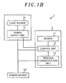
- each of the illumination apparatuses 1 includes, as its major components, a light source 10, a sensor (detection sensor) 11, a control unit 12, a wireless communication unit 13 and a power supply unit 14.
- the light source 10 is formed of a light source capable of being continuously dimmed and capable of being momentarily turned on at a specified illuminance in response to a sensing signal sent from the sensor 11 or a sensing signal wirelessly transmitted from other illumination apparatuses 1.
- the light source 10 is formed of a plurality of LEDs (Light Emitting Diodes).
- the sensor 11 is formed of, e.g., an electric-wave-type Doppler sensor. Upon sensing a moving object (a motor vehicle 4 in the present embodiment), the sensor 11 outputs a sensing signal to the control unit 12.
- the control unit 12 is formed of, e.g., a microcomputer, and is configured to control the output of the light source 10 in response to a sensing signal sent from the sensor 11 or a sensing signal wirelessly transmitted from another illumination apparatus 1.
- the wireless communication unit 13 is formed of a specific small-power wireless module and is configured to perform wireless communication with other illumination apparatuses 1.
- the power supply unit 14 is formed of a chopper circuit for converting a source voltage of a power source 100 to a direct current voltage having a desired voltage value.
- the power supply unit 14 is designed to supply an illumination power to the light source 10 in response to a control signal sent from the control unit 12. Operation power is supplied from the power source 100 to the control unit 12 and the wireless communication unit 13.
- the control unit 12 finds the moving direction of the moving object and decides the illumination apparatuses 1 to which the sensing signal is transmitted depending on the moving direction thus found. More specifically, the moving direction and the address allotted to each of the illumination apparatuses 1 are stored in a storage unit (not shown) in a corresponding relationship with each other. The control unit 12 reads out the corresponding addresses from the storage unit depending on the moving direction. Then, the control unit 12 prepares a transmission signal containing the read-out addresses and the sensing signal and transmits the transmission signal through the wireless communication unit 13.
- each of the illumination apparatuses 1 receiving the transmission signal compares its own address with the addresses contained in the transmission signal. If matched, each of the illumination apparatuses 1 takes the sensing signal contained in the transmission signal and performs the turning-on control of the light source 10. If not matched, each of the illumination apparatuses 1 discards the transmission signal.
- Fig. 1A shows an example in which the light source 10, the sensor 11, the control unit 12, the wireless communication unit 13 and the power supply unit 14 are provided within a single housing.
- the sensor 11, the control unit 12 and the wireless communication unit 13 may be independently provided as an additional apparatus 2.
- the sensing device 3 includes, as its major components, an electric-wave-type Doppler sensor, a wireless communication unit for wirelessly transmitting the sensing signal of the Doppler sensor and a control unit for controlling the operation of the wireless communication unit. If a moving object is sensed by the Doppler sensor, the wireless communication unit transmits a sensing signal to the respective illumination apparatuses 1.
- Fig. 2 is a schematic view illustrating the sensing range of the sensor 11 provided in each of the illumination apparatuses 1.
- the respective illumination apparatuses 1 are installed along one side of a road.
- L1 denotes the installation interval of the illumination apparatuses 1 adjoining to each other.
- W1 denotes the width of a road.
- D1 denotes the major diameter of an elliptical sensing range b of the sensor 11.
- D2 denotes the minor diameter of the elliptical sensing range b of the sensor 11. Accordingly, it is preferable to satisfy the inequality D1 ⁇ L1 and D2 ⁇ W1 in order to prevent sensing failure of the sensor 11 of each of the illumination apparatuses 1.
- Fig. 3 is a schematic configuration view showing one example of the illumination system according to the present embodiment.
- L1 denotes the installation interval of the illumination apparatuses 1 adjoining to each other.
- D1 denotes the sensing range of the sensor 11 in the moving direction of the motor vehicle 4. Do denotes the overlapped sensing range.
- L2 denotes the distance from the motor vehicle 4 to the illumination apparatus 1A when the motor vehicle 4 is first sensed by the sensing device 3 (In Fig. 3 , for the sake of convenience in description, the sensing range of the sensing device 3 is shown to be negligibly small in the longitudinal direction of the road).
- L3 denotes the maximum transmission distance of the sensing signal transmitted from the sensing device 3.
- the transmission distance L3 is, e.g., from 100 m to 150 m.
- D1 and L3 are set to satisfy an inequality L2+2 ⁇ L1 ⁇ L3 ⁇ L2+3 ⁇ L1.
- Figs. 4A to 4D are time charts of the illumination apparatuses 1A to 1D, respectively.
- t2 through t5 denote the time required for the motor vehicle 4 to pass through the respective illumination apparatuses 1A through 1D and to get out of the sensing range of the respective sensors 11.
- the control units 12 of the illumination apparatuses 1A through 1D Prior to time t1 at which the sensing device 3 senses the motor vehicle 4, all the control units 12 of the illumination apparatuses 1A through 1D keep the light sources 10 turned on in a dimmed condition at a low illuminance Lx1. If the sensing device 3 senses the motor vehicle 4, a sensing signal is transmitted from the sensing device 3 to the illumination apparatuses 1A through 1C existing within the range of the transmission distance L3 of the sensing signal of the sensing device 3. Then in the illumination apparatuses 1A through 1C, the control units 12 control the light sources 10 turned on at a high illuminance Lx2 higher than the low illuminance Lx1(Lx2>Lx1). Since the illumination apparatus 1D exists outside the transmission range of the sensing signal of the sensing device 3, the light source 10 thereof is kept turned on in a dimmed condition at a low illuminance Lx1.
- the control unit 12 of the illumination apparatus 1A causes the wireless communication unit 13 thereof to transmit the sensing signal to the illumination apparatuses 1B through 1D.
- the control units 12 of the illumination apparatuses 1B and 1C keep the light sources 10 turned on.
- the control unit 12 of the illumination apparatus 1D turns on the light source 10 at the high illuminance Lx2.
- the time at this moment is the time at which the motor vehicle 4 gets into the sensing range D1 of the sensor 11 of the illumination apparatus 1A and is represented by an equation t1+(L2-D1/2)/S.
- the control unit 12 of the illumination apparatus 1B causes the wireless communication unit 13 thereof to transmit the sensing signal to the illumination apparatuses 1C through 1D.
- the control units 12 of the illumination apparatuses 1C and 1D keep the light sources 10 turned on. If the motor vehicle 4 gets out of the sensing range D1 of the sensor 11 of the illumination apparatus 1A at time t2, the control unit 12 of the illumination apparatus 1A turns on the light source 10 in a dimmed condition at a low illuminance Lx1.
- the control unit 12 of the illumination apparatus 1C causes the wireless communication unit 13 thereof to transmit the sensing signal to the illumination apparatus 1D.
- the control unit 12 of the illumination apparatus 1D keeps the light sources 10 turned on. If the motor vehicle 4 gets out of the sensing range D1 of the sensor 11 of the illumination apparatus 1B at time t3, the control unit 12 of the illumination apparatus 1B turns on the light source 10 in a dimmed condition at the low illuminance Lx1.
- the control unit 12 of the illumination apparatus 1C turns on the light source 10 in a dimmed condition at a low illuminance Lx1.
- the control unit 12 of the illumination apparatus 1D turns on the light source 10 in a dimmed condition at a low illuminance Lx1. At this time, all the light sources 10 of the illumination apparatuses 1A through 1D are kept turned on in a dimmed condition at a low illuminance Lx1.
- Fig. 5 is a schematic configuration view showing another example of the illumination system according to the present embodiment. Alhough the sensing ranges D1 of the adjacent illumination apparatuses are overlapped in the above example, the present example shows the case where the sensing ranges D1 are not overlapped.
- L1 denotes the installation interval of the illumination apparatuses 1 adjoining to each other.
- D1 denotes the sensing range of the sensor 11 in the moving direction of the motor vehicle 4.
- L2 denotes the distance from the motor vehicle 4 to the illumination apparatus 1A when the motor vehicle 4 is first sensed by the sensing device 3 (In Fig.
- the sensing range of the sensing device 3 is shown to be negligibly small in the longitudinal direction of the road).
- L3 denotes the maximum transmission distance of the sensing signal transmitted from the sensing device 3.
- S denotes the speed of the motor vehicle 4.
- the transmission distance L3 is, e.g., from 100 m to 150 m.
- D1 and L3 are set to satisfy an inequality L2+2 ⁇ L1 ⁇ L3 ⁇ L2+3 ⁇ L1.
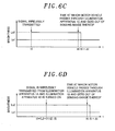
- Figs. 6A through 6D are time charts of the illumination apparatuses 1A through 1D, respectively.
- t2 through t5 denote the time required for the motor vehicle 4 to pass through the respective illumination apparatuses 1A through 1D and to get out of the sensing range of the respective sensors 11.
- ⁇ t denotes the turning-on holding time of the light source 10 after the motor vehicle 4 gets out of the sensing range D1 of the sensor 11.
- the turning-on holding time is set longer than the time taken for the motor vehicle 4 to get out of the sensing range D1 of the previous sensor 11 and to get into the sensing range D1 of the next sensor 11.
- the control units 12 of the illumination apparatuses 1A through 1D Prior to time t1 at which the sensing device 3 senses the motor vehicle 4, all the control units 12 of the illumination apparatuses 1A through 1D keep the light sources 10 turned on in a dimmed condition at a low illuminance Lx1. If the sensing device 3 senses the motor vehicle 4, a sensing signal is transmitted from the sensing device 3. In the illumination apparatuses 1A through 1C existing within the range of the transmission distance L3 of the sensing signal of the sensing device 3, the control units 12 keep the light sources 10 turned on at a high illuminance Lx2 higher than the low illuminance Lx1(Lx2>Lx1). Since the illumination apparatus 1D exists outside the transmission range of the sensing signal of the sensing device 3, the light source 10 thereof is kept turned on in a dimmed condition at a low illuminance Lx1.
- the control units 12 of the respective illumination apparatuses 1A through 1C begin to count the turning-on holding time ⁇ t.
- the motor vehicle 4 gets into the sensing range D1 of the sensor 11 of the illumination apparatus 1A before the counting of the turning-on holding time ⁇ t comes to an end.
- the control unit 12 of the illumination apparatus 1A stops counting the turning-on holding time ⁇ t and keeps the light source 10 turned on.
- the control unit 12 of the illumination apparatus 1A causes the wireless communication unit 13 thereof to transmit the sensing signal to the illumination apparatuses 1B through 1D.
- the control units 12 of the illumination apparatuses 1B and 1C stop counting the turning-on holding time ⁇ t and keep the light sources 10 turned on.
- the control unit 12 of the illumination apparatus 1D turns on the light source 10 at a high illuminance Lx2.
- the time at this moment is the time at which the motor vehicle 4 gets into the sensing range D1 of the sensor 11 of the illumination apparatus 1A and is represented by an equation t1+(L2-D1/2)/S.
- the control units 12 of the respective illumination apparatuses 1A through 1D begin to count the turning-on holding time ⁇ t.
- the motor vehicle 4 gets into the sensing range of the sensor 11 of the illumination apparatus 1B before the counting of the turning-on holding time ⁇ t comes to an end.
- the control unit 12 of the illumination apparatus 1B stops counting the turning-on holding time ⁇ t and keeps the light source 10 turned on.
- the control unit 12 of the illumination apparatus 1B causes the wireless communication unit 13 thereof to transmit the sensing signal to the illumination apparatuses 1C and 1D.
- the control units 12 of the illumination apparatuses 1C and 1D stop counting the turning-on holding time ⁇ t and keep the light sources 10 turned on.
- the illumination apparatus 1A existing ahead of the illumination apparatus 1B cannot receive the sensing signal. Therefore, at time t2+ ⁇ t at which the turning-on holding time ⁇ t lapses, the control unit 12 of the illumination apparatus 1A turns on the light source 10 in a dimmed condition at a low illuminance Lx1.
- the control units 12 of the respective illumination apparatuses 1B through 1D begin to count the turning-on holding time ⁇ t.
- the motor vehicle 4 gets into the sensing range of the sensor 11 of the illumination apparatus 1C before the counting of the turning-on holding time ⁇ t comes to an end.
- the control unit 12 of the illumination apparatus 1C stops counting the turning-on holding time ⁇ t and keeps the light source 10 turned on.
- the control unit 12 of the illumination apparatus 1C causes the wireless communication unit 13 thereof to transmit the sensing signal to the illumination apparatus 1D.
- the control unit 12 of the illumination apparatus 1D Upon receiving the sensing signal, the control unit 12 of the illumination apparatus 1D stops counting the turning-on holding time ⁇ t and keeps the light sources 10 turned on. At this time, the illumination apparatuses 1A and 1B existing ahead of the illumination apparatus 1C cannot receive the sensing signal. Therefore, at time t3+ ⁇ t at which the turning-on holding time ⁇ t lapses, the control unit 12 of the illumination apparatus 1B turns on the light source 10 in a dimmed condition at a low illuminance Lx1.
- the control units 12 of the respective illumination apparatuses 1C and 1D begin to count the turning-on holding time ⁇ t.
- the motor vehicle 4 gets into the sensing range of the sensor 11 of the illumination apparatus 1D before the counting of the turning-on holding time ⁇ t comes to an end.
- the control unit 12 of the illumination apparatus 1D stops counting the turning-on holding time ⁇ t and keeps the light source 10 turned on.
- the illumination apparatuses 1A through 1C existing ahead of the illumination apparatus 1D cannot receive the sensing signal. Therefore, at time t4+ ⁇ t at which the turning-on holding time ⁇ t lapses, the control unit 12 of the illumination apparatus 1C turns on the light source 10 in a dimmed condition at a low illuminance Lx1.
- the control unit 12 of the illumination apparatus 1D begins to count the turning-on holding time ⁇ t. As the counting of the turning-on holding time ⁇ t comes to an end, the control unit 12 of the illumination apparatus 1D turns on the light source 10 in a dimmed condition at a low illuminance Lx1. At this time, all the light sources 10 of the illumination apparatuses 1A through 1D are kept turned on in a dimmed condition at a low illuminance Lx1.
- the illumination conditions of the illumination apparatuses 1 are controlled in response to the moving direction of the motor vehicle 4 in the embodiment described above, the illumination conditions of the illumination apparatuses 1 may be controlled based on the moving speed of a moving object. For example, if the present illumination system is installed in an intersection, the control units 12 of the illumination apparatuses 1 distinguish a low-speed object such as a human or a bicycle from a high-speed object such as a motor vehicle or the like. If the moving object sensed by the sensor 11 is a low-speed object, the control units 12 increase the illuminance of the light sources 10 and cause the illumination apparatuses 1 to broadly illuminate the area including a pedestrian staying place and a pedestrian crossing.
- the illumination apparatuses 1 are kept in a dimmed condition without having to change the illuminance of the light sources 10.
- the light sources 10 are kept in a dimmed condition when a moving object is not sensed or if the moving object is a high-speed object. This makes it possible to save energy.
- the sensing range of the sensor 11 needs to be set to cover a portion of a walkway or a pedestrian staying place.
- the moving speed of a pedestrian is approximately from 4 km/h to 5 km/h and the moving speed of a bicycle is approximately from 20 km/h to 25 km/h.
- a reference speed for determination of a high-speed object and a low-speed object be set equal to about 30 km/h.
- Figs. 7A and 7B are external appearance views showing other examples of the illumination apparatuses 1 employed in the present embodiment.
- Fig. 7A shows a road lamp and
- Fig. 7B shows a tunnel lamp.
- Each of the illumination apparatuses 1 includes a plurality of (three at each side in Figs. 7A and 7B ) auxiliary light sources (e.g., light emitting diodes) 5 for irradiating light in the lateral direction of a device body 15 (in the coming direction of the motor vehicle 4 when installed in place, e.g., in the left-right direction in Fig. 3 ).
- the light sources 10 are kept in a dimmed condition when the motor vehicle 4 gets out of the sensing range of the sensor 11.
- the present embodiment it is possible to secure safety by turning on the light sources 10 at a high illuminance Lx2 when the motor vehicle 4 is sensed by the sensor 11. It is also possible to save energy by turning on the light sources 10 in a dimmed condition at a low illuminance Lx1 when the motor vehicle 4 is not sensed by the sensor 11 and a specified time period is lapsed thereafter. Since wireless communication is performed between the respective illumination apparatuses 1, the wiring lines for interconnecting the respective illumination apparatuses 1 become unnecessary. As a consequence, it is possible to restrain an increase in cost as compared with the prior art example.
- the sensing device 3 is installed ahead of the illumination apparatuses 1. Consequently, even if the moving object is a fast moving object such as a motor vehicle 4 or the like, it is possible to reliably turn on the light sources 10 at the time of passage of the motor vehicle 4.
- the illumination control can be performed depending on the kinds of moving objects by finding the moving speed of the moving objects.
- the moving direction of the moving objects it is possible to turn on the light sources 10 at a high illuminance Lx2 in the moving direction of the moving objects, thereby securing a wide enough illumination range.
- the light sources 10 are turned on in a dimmed condition at a low illuminance Lx1. This makes it possible to save energy.
- the illumination system may be formed of only the illumination apparatuses 1.
- the number of the illumination apparatuses 1 is nothing more than one example and may be set differently, if plural.
- the light sources 10 are formed of LEDs.
- the light sources 10 may be formed of other light sources capable of being continuously dimmed and capable of being momentarily turned on at a specified illuminance.
- the moving object is not limited to the motor vehicle 4 but may be a human, a bicycle or other moving bodies.
- the light sources 10 are turned on in a dimmed condition at a low illuminance Lx1 when the motor vehicle 4 is not sensed by the sensor 11 or the sensing device 3. Alternatively, the light sources 10 may be turned off, in which case it becomes possible to further save energy.
- the transmission distance L3 of the sensing signal of the sensing device 3, the sensing range D1 of the sensor 11 and the installation interval L1 of the respective illumination apparatuses 1 are nothing more than one example and may be arbitrarily set depending on the installation environment and so forth.
- the illumination conditions of the illumination apparatuses 1 are controlled in response to one of the moving direction and speed of the moving objects. Alternatively, the illumination conditions of the illumination apparatuses 1 may be controlled based on both of the moving direction and speed of the moving objects.
Landscapes
- Engineering & Computer Science (AREA)
- Computer Networks & Wireless Communication (AREA)
- Circuit Arrangement For Electric Light Sources In General (AREA)
Claims (10)
- Beleuchtungsvorrichtung (1), die ausgelegt ist, um mit anderen Beleuchtungsvorrichtungen (1) verwendet zu werden, umfassend:eine Lichtquelle (10);einen Erfassungssensor (11), der ausgelegt ist, um die Anwesenheit eines sich bewegenden Objekts (4) wahr zu nehmen, um dabei ein Erfassungssignal zu erzeugen;eine drahtlose Kommunikationseinheit (13), die ausgelegt ist, um das ErfassungsSignal drahtlos zu wenigstens einer von den anderen Beleuchtungsvorrichtungen (1) innerhalb eines Übertragungsbereichs des Erfassungssignals zu übertragen und um ein Erfassungssignal von jeder der wenigstens einen anderen Beleuchtungsvorrichtungen (1) zu empfangen; undeine Steuereinheit (12), die ausgelegt ist, um eine Ausgabe der Lichtquelle (10) basierend auf dem erzeugten Erfassungssignal oder dem empfangenen Erfassungssignal zu steuern,wobei der Erfassungssensor (11) ausgelegt ist, um das erzeugte Erfassungssignal zu der Steuereinheit (12) auszugeben, undwobei die Beleuchtungsvorrichtung (1) konfiguriert ist, um, wenn der Erfassungssensor (11) die Anwesenheit eines sich bewegenden Objekts (4) wahrnimmt, das erzeugte Erfassungssignal drahtlos zu wenigstens einer der anderen Beleuchtungsvorrichtungen (1) zu übertragen und um es wenigstens einer oder mehreren der wenigstens einen der anderen Beleuchtungsvorrichtungen (1) zu ermöglichen, zusammen gesteuert zu werden, dadurch gekennzeichnet, dassdie Steuereinheit (12) konfiguriert ist, um, wenn der Erfassungssensor (11) die Anwesenheit des sich bewegenden Objekts (4) wahrnimmt, eine Bewegungsgeschwindigkeit des sich bewegenden Objekts (4) heraus zu finden und zu bestimmen, ob es sich bei dem sich bewegende Objekt (4) um ein Niedriggeschwindigkeits-Objekt oder um ein Hochgeschwindigkeits-Objekt handelt, wobei das sich bewegende Objekt als das Niedriggeschwindigkeits-Objekt bestimmt wird, wenn die Bewegungsgeschwindigkeit niedriger als ein Grenzwert liegt und als das Hochgeschwindigkeits-Objekt im anderen Fall, undwobei die Steuereinheit (12) ausgelegt ist, um die Lichtquelle (10) derart zu steuern, dass eine Beleuchtungsstärke der Lichtquelle (10) größer ausfällt, wenn bestimmt wird, dass es sich bei dem sich bewegenden Objekt (4) um das Niedriggeschwindigkeits-Objekt handelt, als wenn bestimmt wird, dass es sich bei dem sich bewegenden Objekt (4) um das Hochgeschwindigkeits-Objekt handelt.
- Vorrichtung (1) gemäß Anspruch 1, bei der die Steuereinheit (12) ausgelegt ist, um die Lichtquelle (10) derart zu steuern, um kontinuierlich gedimmt zu werden und um in Reaktion auf das erzeugt Erfassungssignal oder das empfangene Erfassungssignal abrupt angeschaltet zu werden.
- Vorrichtung (1) gemäß Anspruch 1 oder 2, bei der, wenn der Erfassungssensor (11) die Anwesenheit des sich bewegenden Objekts (4) wahrnimmt. oder, wenn die drahtlose Kommunikationseinheit (13) das Erfassungssignal von der wenigstens einen der anderen Beleuchtungsvorrichtungen (1) empfängt, die Steuereinheit (12) ausgelegt ist, um die Lichtquelle (10) mit einer festgelegten Beleuchtungsstärke anzuschalten;
wenn der Erfassungssensor (11) keine Anwesenheit des sich bewegenden Objekts (4) wahrnimmt und, wenn die drahtlose Kommunikationseinheit (13) kein Erfassungssignal von der wenigstens einen der anderen Beleuchtungsvorrichtungen (1) empfängt, die Steuereinheit (12) ausgelegt ist, um die Lichtquelle (10) mit einer Beleuchtungsstärke anzuschalten, die geringer ist als die festgelegte Beleuchtungsstärke oder die Lichtquelle (10) nachdem eine vorgegebenen Zeit vergangen ist, ausgeschaltet wird. - Beleuchtungssystem umfassend mehrere Beleuchtungsvorrichtungen (1) gemäß Anspruch 1,
bei der, wenn der Erfassungssensor (13) von einer der mehreren Beleuchtungsvorrichtungen (1) das sich bewegende Objekt (4) wahrnimmt, wenigstens eine von den anderen der mehreren Beleuchtungsvorrichtungen (1) innerhalb des Übertragungsbereichs des erzeugten Erfassungssignals zusammen über das drahtlos übertragene Erfassungssignal von der einen der mehreren Beleuchtungsvorrichtungen gesteuert wird. - System gemäß Anspruch 4, bei der die Steuereinheit (12) von jeder der mehreren Beleuchtungsvorrichtungen (1) ausgelegt ist, um die jeweilige Lichtquelle (10) derart zu steuern, um kontinuierlich gedimmt zu werden und in Reaktion auf das erzeugte Erfassungssignal oder das empfangene Erfassungssignal abrupt angeschaltet zu werden.
- System gemäß Anspruch 4 oder 5, weiter umfassend:eine Erfassungsvorrichtung (3), die ausgelegt ist, um eine Anwesenheit des sich bewegenden Objekts (4) in einem Erfassungsbereich, der sich von einem Erfassungsbereich des Erfassungssensors (11) von jeder der mehreren Beleuchtungsvorrichtungen (1) unterscheidet, wahr zu nehmen, und, um drahtlos ein Erfassungssignal zu wenigstens einer der mehreren Beleuchtungsvorrichtungen (1) zu übertragen.
- System gemäß einem der Ansprüche 4 bis 6, bei dem jede der Beleuchtungsvorrichtungen (1) konfiguriert ist, um, wenn der Erfassungssensor (11) die Anwesenheit des sich bewegenden Objekts (4) wahrnimmt, oder, wenn die drahtlose Kommunikationseinheit (13) das Erfassungssignal von der wenigstens einen der anderen Beleuchtungsvorrichtungen (1) oder der Erfassungsvorrichtung (3) empfängt, die Lichtquelle (10) bei einer festgelegten Beleuchtungsstärke anzuschalten, und konfiguriert ist, um, wenn der Erfassungssensor (11) die Anwesenheit des sich bewegenden Objekts (4) nicht wahrnimmt, und wenn die drahtlose Kommunikationseinheit (13) kein Erfassungssignal von der wenigstens einen der anderen Beleuchtungsvorrichtungen (1) oder von der Erfassungsvorrichtung (3) empfängt, die Lichtquelle (10) mit einer Beleuchtungsstärke anzuschalten, die geringer ist, als die festgelegte Beleuchtungsstärke oder die Lichtquelle (10) nachdem eine bestimmte Zeit vergangen ist, ausschaltet.
- System gemäß Anspruch 6, bei der jede der Beleuchtungsvorrichtungen, die innerhalb eines Übertragungsbereichs des Erfassungssignals der Erfassungsvorrichtung (3) und vor dem sich bewegenden Objekt (4) in einer Vorlaufrichtung des sich bewegenden Objekts (4) bezüglich der Erfassungsvorrichtung (3) angeordnet ist, konfiguriert ist, um bei Empfang des Erfassungssignals von der Erfassungsvorrichtung, die Lichtquelle bei einer festgelegten Beleuchtungsstärke anzuschalten, und konfiguriert ist, um, wenn das sich bewegende Objekt (4) aus dem Erfassungsbereich des Erfassungssensors (11) gerät, die Lichtquelle mit einer Beleuchtungsstärke anschaltet, die geringer ist, als die festgelegte Beleuchtungsstärke, oder die Lichtquelle (10) nach einem Ablauf einer festgelegten Zeit ausschaltet.
- System gemäß einem der Ansprüche 4 bis 8, bei dem jede der Beleuchtungsvorrichtungen (1) eine Hilfs-Lichtquelle (5) für ein Ausstrahlen von Licht auf das sich bewegende Objekt (4) umfasst.
- System gemäß einem der Ansprüche 4 bis 9, bei dem die Steuereinheit (12) von einer der mehreren Beleuchtungsvorrichtungen (1) ausgelegt ist, um, wenn der Erfassungssensor (11) das sich bewegende Objekt (4) wahrnimmt, eine Bewegungsrichtung des sich bewegenden Objekts (4) heraus zu finden, und um eine Übertragung und Nichtübertragung des Erfassungssignals zu den anderen der mehreren Beleuchtungsvorrichtungen in Abhängigkeit von der so herausgefundenen Bewegungsrichtung zu entscheiden.
Applications Claiming Priority (1)
| Application Number | Priority Date | Filing Date | Title |
|---|---|---|---|
| JP2011093792A JP2012226993A (ja) | 2011-04-20 | 2011-04-20 | 照明システム |
Publications (2)
| Publication Number | Publication Date |
|---|---|
| EP2515618A1 EP2515618A1 (de) | 2012-10-24 |
| EP2515618B1 true EP2515618B1 (de) | 2015-09-09 |
Family
ID=46049142
Family Applications (1)
| Application Number | Title | Priority Date | Filing Date |
|---|---|---|---|
| EP12002698.4A Active EP2515618B1 (de) | 2011-04-20 | 2012-04-18 | Beleuchtungssystem und beleuchtungsvorrichtung |
Country Status (4)
| Country | Link |
|---|---|
| US (1) | US8981671B2 (de) |
| EP (1) | EP2515618B1 (de) |
| JP (1) | JP2012226993A (de) |
| CN (1) | CN102752911B (de) |
Families Citing this family (44)
| Publication number | Priority date | Publication date | Assignee | Title |
|---|---|---|---|---|
| US8203445B2 (en) * | 2006-03-28 | 2012-06-19 | Wireless Environment, Llc | Wireless lighting |
| CN103181242B (zh) * | 2010-11-02 | 2015-08-19 | 皇家飞利浦电子股份有限公司 | 具有雷达检测的照明系统 |
| US20140103814A1 (en) * | 2012-03-15 | 2014-04-17 | General Electric Company | Communication system for adaptive lighting control |
| US10721808B2 (en) | 2012-07-01 | 2020-07-21 | Ideal Industries Lighting Llc | Light fixture control |
| US9980350B2 (en) | 2012-07-01 | 2018-05-22 | Cree, Inc. | Removable module for a lighting fixture |
| US9872367B2 (en) | 2012-07-01 | 2018-01-16 | Cree, Inc. | Handheld device for grouping a plurality of lighting fixtures |
| US10219338B2 (en) | 2012-07-01 | 2019-02-26 | Cree, Inc. | Modular lighting control |
| US9572226B2 (en) | 2012-07-01 | 2017-02-14 | Cree, Inc. | Master/slave arrangement for lighting fixture modules |
| KR101232465B1 (ko) * | 2012-08-15 | 2013-02-12 | 윤영철 | 복합센서를 구비한 조명장치 및 연동형 조명 시스템 |
| EP2935988B1 (de) * | 2012-12-18 | 2019-01-30 | Cree, Inc. | Leuchte für verteilte steuerung |
| US9913348B2 (en) | 2012-12-19 | 2018-03-06 | Cree, Inc. | Light fixtures, systems for controlling light fixtures, and methods of controlling fixtures and methods of controlling lighting control systems |
| DE102013100233A1 (de) * | 2013-01-10 | 2014-07-10 | Bahner Lichttechnik GmbH | Beleuchtungsanlage mit einer Mehrzahl von Leuchten und einer Mehrzahl von Sensoren sowie Beleuchtungsanlagensensor, Leuchte und Verfahren zur Beleuchtung einer Fläche |
| US11304276B2 (en) | 2013-02-26 | 2022-04-12 | Ideal Industries Lighting Llc | Glare-reactive lighting apparatus |
| JP2014185834A (ja) * | 2013-03-25 | 2014-10-02 | Toshiba Lighting & Technology Corp | 電気機器制御システム |
| EP2995175B1 (de) * | 2013-05-07 | 2018-02-21 | Philips Lighting Holding B.V. | Lampe für strassenbeleuchtung mit sensor |
| JP6032611B2 (ja) * | 2013-05-23 | 2016-11-30 | パナソニックIpマネジメント株式会社 | 無線通信装置及び無線通信システム |
| JP2014229552A (ja) * | 2013-05-24 | 2014-12-08 | パナソニック株式会社 | 照明システム |
| JP6155529B2 (ja) | 2013-05-31 | 2017-07-05 | パナソニックIpマネジメント株式会社 | 照明システム |
| CN104735856B (zh) * | 2013-12-24 | 2019-04-05 | 欧普照明股份有限公司 | 一种停车场照明系统 |
| US10154569B2 (en) | 2014-01-06 | 2018-12-11 | Cree, Inc. | Power over ethernet lighting fixture |
| JP6340537B2 (ja) * | 2014-03-31 | 2018-06-13 | マイクロコントロールシステムズ株式会社 | 通行体の通行・移動区域に適した照明システム、照明灯及び照明方法 |
| US10278250B2 (en) | 2014-05-30 | 2019-04-30 | Cree, Inc. | Lighting fixture providing variable CCT |
| JP6414736B2 (ja) | 2014-09-08 | 2018-10-31 | パナソニックIpマネジメント株式会社 | 照明装置及び照明システム |
| CN104394616A (zh) * | 2014-11-03 | 2015-03-04 | 合肥意成信息科技有限公司 | 一种通过射频技术自动控制路灯系统 |
| US9877374B2 (en) * | 2014-11-25 | 2018-01-23 | Cree, Inc. | Lighting apparatus and methods providing variable illumination characteristics based on object detection |
| CN104582186B (zh) * | 2015-01-14 | 2017-01-25 | 北京丹普法莫物联网科技有限责任公司 | 一种基于物联网视觉俘获的照明系统及其控制方法 |
| WO2016124409A1 (en) * | 2015-02-05 | 2016-08-11 | Philips Lighting Holding B.V. | Road lighting |
| JP6512509B2 (ja) * | 2015-03-11 | 2019-05-15 | パナソニックIpマネジメント株式会社 | 動体検知装置及び照明システム |
| CN107836138A (zh) * | 2015-05-26 | 2018-03-23 | Idd航空宇宙公司 | 飞行器中基于可移动对象的位置的可调节照明 |
| US9930752B2 (en) * | 2015-11-10 | 2018-03-27 | General Electric Company | Image sensor controlled lighting fixture |
| US9743493B2 (en) * | 2015-12-09 | 2017-08-22 | General Electric Company | Methods, apparatus, system and media for use in association with lighting systems |
| US9967944B2 (en) | 2016-06-22 | 2018-05-08 | Cree, Inc. | Dimming control for LED-based luminaires |
| US10595380B2 (en) | 2016-09-27 | 2020-03-17 | Ideal Industries Lighting Llc | Lighting wall control with virtual assistant |
| US20180139821A1 (en) * | 2016-11-14 | 2018-05-17 | General Electric Company | Method and apparatus for autonomous lighting control |
| AT16037U1 (de) * | 2017-04-28 | 2018-11-15 | Tridonic Gmbh & Co Kg | Verfahren zur Steuerung eines Beleuchtungssystems |
| US10449895B2 (en) * | 2018-03-20 | 2019-10-22 | Rockwell Collins, Inc. | Object tracking illumination system |
| EP4224891A3 (de) | 2018-08-28 | 2023-10-11 | Signify Holding B.V. | Steuerung zur steuerung eines drahtlosen netzwerks zur durchführung von hochfrequenzbasierten diensten |
| CN110035592A (zh) * | 2019-05-28 | 2019-07-19 | 莆田市烛火信息技术有限公司 | 一种智慧城市交通照明控制服务系统 |
| CN110290587B (zh) * | 2019-07-22 | 2025-05-02 | 深圳迈睿智能科技有限公司 | 一种多信道窄频通讯方法及其系统和照明设备 |
| CN110856321A (zh) * | 2019-12-05 | 2020-02-28 | 山西汇智科技有限责任公司 | 隧道智能灯系统及其信息传递方法 |
| CN111315089A (zh) * | 2019-12-05 | 2020-06-19 | 山西汇智科技有限责任公司 | 一种隧道人体感应智能灯装置 |
| CN111629473B (zh) * | 2020-06-05 | 2021-12-28 | 连云港杰瑞电子有限公司 | 一种港口照明智能控制系统及方法 |
| WO2023044302A1 (en) * | 2021-09-14 | 2023-03-23 | Witricity Corporation | Systems and methods for pairing wireless power receivers and transmitters |
| CN116887492A (zh) * | 2023-06-16 | 2023-10-13 | 厦门普为光电科技有限公司 | 具有联动式感应机制的照明系统 |
Citations (1)
| Publication number | Priority date | Publication date | Assignee | Title |
|---|---|---|---|---|
| US20100029268A1 (en) * | 2007-02-02 | 2010-02-04 | Ming Solar, Inc., Dba Inovus Solar, Inc. | Wireless autonomous solar-powered outdoor lighting and energy and information management network |
Family Cites Families (18)
| Publication number | Priority date | Publication date | Assignee | Title |
|---|---|---|---|---|
| JPH04342986A (ja) * | 1991-05-20 | 1992-11-30 | Nissan Motor Co Ltd | 道路照明システム |
| JPH05283173A (ja) | 1992-03-17 | 1993-10-29 | Nissan Motor Co Ltd | 道路照明システム |
| JPH10334711A (ja) | 1997-06-02 | 1998-12-18 | Matsushita Electric Ind Co Ltd | トンネル灯制御装置 |
| JP3867368B2 (ja) * | 1997-10-15 | 2007-01-10 | 松下電工株式会社 | 照明装置 |
| JP2001102182A (ja) | 1999-09-30 | 2001-04-13 | Toshiba Corp | 道路照明の点灯制御システム及び道路照明の点灯制御方法 |
| JP2001175994A (ja) * | 1999-12-22 | 2001-06-29 | Matsushita Electric Works Ltd | 照明装置 |
| JP2002305088A (ja) * | 2001-04-03 | 2002-10-18 | Toshiba Corp | 道路照明システム |
| JP2004241217A (ja) | 2003-02-05 | 2004-08-26 | Yamatake Corp | 屋外照明装置 |
| CA2692187A1 (en) * | 2007-06-29 | 2009-01-08 | Carmanah Technologies Corp. | Intelligent area lighting system |
| JP2009054496A (ja) * | 2007-08-28 | 2009-03-12 | Panasonic Electric Works Co Ltd | 照明制御システム |
| JP5240705B2 (ja) * | 2007-10-26 | 2013-07-17 | パナソニック株式会社 | 点灯保持時間可変式照明システム |
| JP2009259584A (ja) * | 2008-04-16 | 2009-11-05 | Nippon Dempa Kogyo Co Ltd | 街灯点灯制御装置 |
| CN101267703B (zh) * | 2008-04-30 | 2012-04-25 | 张少甫 | 一种节能的路灯亮度随需动态调节系统及控制方法 |
| US8497634B2 (en) * | 2008-10-23 | 2013-07-30 | Innovation Works, Inc. | Wireless lighting system for staircases and passageways |
| JP5279464B2 (ja) * | 2008-11-25 | 2013-09-04 | パナソニック株式会社 | トンネル用照明器具及びそれを用いたトンネル用照明システム |
| KR100962341B1 (ko) * | 2009-06-24 | 2010-06-23 | (주)텔코아 시스템 | 분할형 led 가로등 |
| TWM392908U (en) | 2010-01-13 | 2010-11-21 | Zeng Yong Teng | Energy-saving sensing control device for LED road lamp |
| KR100981274B1 (ko) * | 2010-03-11 | 2010-09-10 | 주식회사 베스트디지탈 | 자동 조명제어 시스템 |
-
2011
- 2011-04-20 JP JP2011093792A patent/JP2012226993A/ja active Pending
-
2012
- 2012-04-18 US US13/449,597 patent/US8981671B2/en active Active
- 2012-04-18 EP EP12002698.4A patent/EP2515618B1/de active Active
- 2012-04-19 CN CN201210116633.XA patent/CN102752911B/zh active Active
Patent Citations (1)
| Publication number | Priority date | Publication date | Assignee | Title |
|---|---|---|---|---|
| US20100029268A1 (en) * | 2007-02-02 | 2010-02-04 | Ming Solar, Inc., Dba Inovus Solar, Inc. | Wireless autonomous solar-powered outdoor lighting and energy and information management network |
Also Published As
| Publication number | Publication date |
|---|---|
| US8981671B2 (en) | 2015-03-17 |
| EP2515618A1 (de) | 2012-10-24 |
| CN102752911A (zh) | 2012-10-24 |
| CN102752911B (zh) | 2015-09-30 |
| US20120268034A1 (en) | 2012-10-25 |
| JP2012226993A (ja) | 2012-11-15 |
Similar Documents
| Publication | Publication Date | Title |
|---|---|---|
| US8981671B2 (en) | Illumination system and illumination apparatus | |
| JP5690347B2 (ja) | 照明装置及び照明システム | |
| KR101044224B1 (ko) | 차량감응 하이브리드가로등 제어 시스템 및 방법 | |
| KR101941578B1 (ko) | 태양광 유도등 및 이를 이용한 유도시스템 | |
| JP6841020B2 (ja) | ポジション照明装置および車両 | |
| US20160176333A1 (en) | Method for the operation of a headlight and motor vehicle headlight | |
| KR101905125B1 (ko) | 스마트 터널등 제어 시스템 및 그 방법 | |
| GB2470926A (en) | Lighting system with sensor controlled illumination groups | |
| CN112738956B (zh) | 汽车室内灯照明自适应系统及控制方法 | |
| US20100148696A1 (en) | Method for controlling the emission behavior of luminaires in an arrangement of a plurality of luminaires, and an arrangement of a plurality of luminaires | |
| US20130278146A1 (en) | Selective street light control apparatus, systems, and methods | |
| KR101429123B1 (ko) | 센서 노드, 교차로 안전 시스템 및 교차로 안전 시스템의 제어 방법 | |
| EP3101386A1 (de) | Parkhilfesystem | |
| KR20220112607A (ko) | 인공 지능형 교통 신호등 | |
| KR20140105281A (ko) | 위치 및 속도기반 가로등 점등 시스템 및 방법 | |
| KR20140122507A (ko) | 인접 그룹별로 점등하는 독립형 조명 제어장치 | |
| KR102081840B1 (ko) | 게이트웨이를 이용한 제어 시스템 및 제어 방법 | |
| KR20150000098A (ko) | Led 조명 제어 시스템 | |
| KR20100135581A (ko) | 디밍 제어 엘이디 안정기 | |
| KR102450754B1 (ko) | 차선간 차량 유무 인지가 가능한 가로등 제어 시스템 및 그 방법 | |
| KR100410862B1 (ko) | 헤드램프 조사각도 자동 조절장치 | |
| EP2670222B1 (de) | Beleuchtungssteuerungssystem | |
| KR102273977B1 (ko) | 차량용 전조등의 색상 제어 시스템 | |
| KR20110021457A (ko) | 트레일러 후미등의 무선 제어 시스템 및 방법 | |
| KR102292213B1 (ko) | 무선통신을 이용한 모형 자동차의 주행 자동 제어시스템 |
Legal Events
| Date | Code | Title | Description |
|---|---|---|---|
| PUAI | Public reference made under article 153(3) epc to a published international application that has entered the european phase |
Free format text: ORIGINAL CODE: 0009012 |
|
| AK | Designated contracting states |
Kind code of ref document: A1 Designated state(s): AL AT BE BG CH CY CZ DE DK EE ES FI FR GB GR HR HU IE IS IT LI LT LU LV MC MK MT NL NO PL PT RO RS SE SI SK SM TR |
|
| AX | Request for extension of the european patent |
Extension state: BA ME |
|
| 17P | Request for examination filed |
Effective date: 20130410 |
|
| 17Q | First examination report despatched |
Effective date: 20141121 |
|
| RAP1 | Party data changed (applicant data changed or rights of an application transferred) |
Owner name: PANASONIC INTELLECTUAL PROPERTY MANAGEMENT CO., LT |
|
| GRAP | Despatch of communication of intention to grant a patent |
Free format text: ORIGINAL CODE: EPIDOSNIGR1 |
|
| RIC1 | Information provided on ipc code assigned before grant |
Ipc: H05B 37/02 20060101AFI20150413BHEP Ipc: F21W 131/103 20060101ALI20150413BHEP |
|
| INTG | Intention to grant announced |
Effective date: 20150429 |
|
| GRAS | Grant fee paid |
Free format text: ORIGINAL CODE: EPIDOSNIGR3 |
|
| GRAA | (expected) grant |
Free format text: ORIGINAL CODE: 0009210 |
|
| AK | Designated contracting states |
Kind code of ref document: B1 Designated state(s): AL AT BE BG CH CY CZ DE DK EE ES FI FR GB GR HR HU IE IS IT LI LT LU LV MC MK MT NL NO PL PT RO RS SE SI SK SM TR |
|
| REG | Reference to a national code |
Ref country code: GB Ref legal event code: FG4D |
|
| REG | Reference to a national code |
Ref country code: AT Ref legal event code: REF Ref document number: 749010 Country of ref document: AT Kind code of ref document: T Effective date: 20150915 Ref country code: CH Ref legal event code: EP |
|
| REG | Reference to a national code |
Ref country code: IE Ref legal event code: FG4D |
|
| REG | Reference to a national code |
Ref country code: DE Ref legal event code: R096 Ref document number: 602012010236 Country of ref document: DE |
|
| REG | Reference to a national code |
Ref country code: NL Ref legal event code: MP Effective date: 20150909 |
|
| PG25 | Lapsed in a contracting state [announced via postgrant information from national office to epo] |
Ref country code: NO Free format text: LAPSE BECAUSE OF FAILURE TO SUBMIT A TRANSLATION OF THE DESCRIPTION OR TO PAY THE FEE WITHIN THE PRESCRIBED TIME-LIMIT Effective date: 20151209 Ref country code: LV Free format text: LAPSE BECAUSE OF FAILURE TO SUBMIT A TRANSLATION OF THE DESCRIPTION OR TO PAY THE FEE WITHIN THE PRESCRIBED TIME-LIMIT Effective date: 20150909 Ref country code: LT Free format text: LAPSE BECAUSE OF FAILURE TO SUBMIT A TRANSLATION OF THE DESCRIPTION OR TO PAY THE FEE WITHIN THE PRESCRIBED TIME-LIMIT Effective date: 20150909 Ref country code: FI Free format text: LAPSE BECAUSE OF FAILURE TO SUBMIT A TRANSLATION OF THE DESCRIPTION OR TO PAY THE FEE WITHIN THE PRESCRIBED TIME-LIMIT Effective date: 20150909 Ref country code: GR Free format text: LAPSE BECAUSE OF FAILURE TO SUBMIT A TRANSLATION OF THE DESCRIPTION OR TO PAY THE FEE WITHIN THE PRESCRIBED TIME-LIMIT Effective date: 20151210 |
|
| REG | Reference to a national code |
Ref country code: LT Ref legal event code: MG4D |
|
| REG | Reference to a national code |
Ref country code: AT Ref legal event code: MK05 Ref document number: 749010 Country of ref document: AT Kind code of ref document: T Effective date: 20150909 |
|
| PG25 | Lapsed in a contracting state [announced via postgrant information from national office to epo] |
Ref country code: RS Free format text: LAPSE BECAUSE OF FAILURE TO SUBMIT A TRANSLATION OF THE DESCRIPTION OR TO PAY THE FEE WITHIN THE PRESCRIBED TIME-LIMIT Effective date: 20150909 Ref country code: HR Free format text: LAPSE BECAUSE OF FAILURE TO SUBMIT A TRANSLATION OF THE DESCRIPTION OR TO PAY THE FEE WITHIN THE PRESCRIBED TIME-LIMIT Effective date: 20150909 Ref country code: ES Free format text: LAPSE BECAUSE OF FAILURE TO SUBMIT A TRANSLATION OF THE DESCRIPTION OR TO PAY THE FEE WITHIN THE PRESCRIBED TIME-LIMIT Effective date: 20150909 Ref country code: SE Free format text: LAPSE BECAUSE OF FAILURE TO SUBMIT A TRANSLATION OF THE DESCRIPTION OR TO PAY THE FEE WITHIN THE PRESCRIBED TIME-LIMIT Effective date: 20150909 |
|
| PG25 | Lapsed in a contracting state [announced via postgrant information from national office to epo] |
Ref country code: NL Free format text: LAPSE BECAUSE OF FAILURE TO SUBMIT A TRANSLATION OF THE DESCRIPTION OR TO PAY THE FEE WITHIN THE PRESCRIBED TIME-LIMIT Effective date: 20150909 |
|
| PG25 | Lapsed in a contracting state [announced via postgrant information from national office to epo] |
Ref country code: SK Free format text: LAPSE BECAUSE OF FAILURE TO SUBMIT A TRANSLATION OF THE DESCRIPTION OR TO PAY THE FEE WITHIN THE PRESCRIBED TIME-LIMIT Effective date: 20150909 Ref country code: IS Free format text: LAPSE BECAUSE OF FAILURE TO SUBMIT A TRANSLATION OF THE DESCRIPTION OR TO PAY THE FEE WITHIN THE PRESCRIBED TIME-LIMIT Effective date: 20160109 Ref country code: EE Free format text: LAPSE BECAUSE OF FAILURE TO SUBMIT A TRANSLATION OF THE DESCRIPTION OR TO PAY THE FEE WITHIN THE PRESCRIBED TIME-LIMIT Effective date: 20150909 Ref country code: CZ Free format text: LAPSE BECAUSE OF FAILURE TO SUBMIT A TRANSLATION OF THE DESCRIPTION OR TO PAY THE FEE WITHIN THE PRESCRIBED TIME-LIMIT Effective date: 20150909 Ref country code: IT Free format text: LAPSE BECAUSE OF FAILURE TO SUBMIT A TRANSLATION OF THE DESCRIPTION OR TO PAY THE FEE WITHIN THE PRESCRIBED TIME-LIMIT Effective date: 20150909 |
|
| PG25 | Lapsed in a contracting state [announced via postgrant information from national office to epo] |
Ref country code: PT Free format text: LAPSE BECAUSE OF FAILURE TO SUBMIT A TRANSLATION OF THE DESCRIPTION OR TO PAY THE FEE WITHIN THE PRESCRIBED TIME-LIMIT Effective date: 20160111 Ref country code: RO Free format text: LAPSE BECAUSE OF FAILURE TO SUBMIT A TRANSLATION OF THE DESCRIPTION OR TO PAY THE FEE WITHIN THE PRESCRIBED TIME-LIMIT Effective date: 20150909 Ref country code: PL Free format text: LAPSE BECAUSE OF FAILURE TO SUBMIT A TRANSLATION OF THE DESCRIPTION OR TO PAY THE FEE WITHIN THE PRESCRIBED TIME-LIMIT Effective date: 20150909 Ref country code: AT Free format text: LAPSE BECAUSE OF FAILURE TO SUBMIT A TRANSLATION OF THE DESCRIPTION OR TO PAY THE FEE WITHIN THE PRESCRIBED TIME-LIMIT Effective date: 20150909 |
|
| REG | Reference to a national code |
Ref country code: DE Ref legal event code: R097 Ref document number: 602012010236 Country of ref document: DE |
|
| PLBE | No opposition filed within time limit |
Free format text: ORIGINAL CODE: 0009261 |
|
| STAA | Information on the status of an ep patent application or granted ep patent |
Free format text: STATUS: NO OPPOSITION FILED WITHIN TIME LIMIT |
|
| 26N | No opposition filed |
Effective date: 20160610 |
|
| PG25 | Lapsed in a contracting state [announced via postgrant information from national office to epo] |
Ref country code: BE Free format text: LAPSE BECAUSE OF NON-PAYMENT OF DUE FEES Effective date: 20160430 Ref country code: DK Free format text: LAPSE BECAUSE OF FAILURE TO SUBMIT A TRANSLATION OF THE DESCRIPTION OR TO PAY THE FEE WITHIN THE PRESCRIBED TIME-LIMIT Effective date: 20150909 Ref country code: SI Free format text: LAPSE BECAUSE OF FAILURE TO SUBMIT A TRANSLATION OF THE DESCRIPTION OR TO PAY THE FEE WITHIN THE PRESCRIBED TIME-LIMIT Effective date: 20150909 |
|
| REG | Reference to a national code |
Ref country code: CH Ref legal event code: PL |
|
| GBPC | Gb: european patent ceased through non-payment of renewal fee |
Effective date: 20160418 |
|
| PG25 | Lapsed in a contracting state [announced via postgrant information from national office to epo] |
Ref country code: LU Free format text: LAPSE BECAUSE OF FAILURE TO SUBMIT A TRANSLATION OF THE DESCRIPTION OR TO PAY THE FEE WITHIN THE PRESCRIBED TIME-LIMIT Effective date: 20160418 Ref country code: BE Free format text: LAPSE BECAUSE OF FAILURE TO SUBMIT A TRANSLATION OF THE DESCRIPTION OR TO PAY THE FEE WITHIN THE PRESCRIBED TIME-LIMIT Effective date: 20150909 |
|
| REG | Reference to a national code |
Ref country code: IE Ref legal event code: MM4A |
|
| REG | Reference to a national code |
Ref country code: FR Ref legal event code: ST Effective date: 20161230 |
|
| PG25 | Lapsed in a contracting state [announced via postgrant information from national office to epo] |
Ref country code: FR Free format text: LAPSE BECAUSE OF NON-PAYMENT OF DUE FEES Effective date: 20160502 Ref country code: GB Free format text: LAPSE BECAUSE OF NON-PAYMENT OF DUE FEES Effective date: 20160418 Ref country code: CH Free format text: LAPSE BECAUSE OF NON-PAYMENT OF DUE FEES Effective date: 20160430 Ref country code: LI Free format text: LAPSE BECAUSE OF NON-PAYMENT OF DUE FEES Effective date: 20160430 |
|
| PG25 | Lapsed in a contracting state [announced via postgrant information from national office to epo] |
Ref country code: IE Free format text: LAPSE BECAUSE OF NON-PAYMENT OF DUE FEES Effective date: 20160418 |
|
| PG25 | Lapsed in a contracting state [announced via postgrant information from national office to epo] |
Ref country code: SM Free format text: LAPSE BECAUSE OF FAILURE TO SUBMIT A TRANSLATION OF THE DESCRIPTION OR TO PAY THE FEE WITHIN THE PRESCRIBED TIME-LIMIT Effective date: 20150909 Ref country code: HU Free format text: LAPSE BECAUSE OF FAILURE TO SUBMIT A TRANSLATION OF THE DESCRIPTION OR TO PAY THE FEE WITHIN THE PRESCRIBED TIME-LIMIT; INVALID AB INITIO Effective date: 20120418 Ref country code: CY Free format text: LAPSE BECAUSE OF FAILURE TO SUBMIT A TRANSLATION OF THE DESCRIPTION OR TO PAY THE FEE WITHIN THE PRESCRIBED TIME-LIMIT Effective date: 20150909 |
|
| PG25 | Lapsed in a contracting state [announced via postgrant information from national office to epo] |
Ref country code: MK Free format text: LAPSE BECAUSE OF FAILURE TO SUBMIT A TRANSLATION OF THE DESCRIPTION OR TO PAY THE FEE WITHIN THE PRESCRIBED TIME-LIMIT Effective date: 20150909 Ref country code: MT Free format text: LAPSE BECAUSE OF NON-PAYMENT OF DUE FEES Effective date: 20160430 Ref country code: TR Free format text: LAPSE BECAUSE OF FAILURE TO SUBMIT A TRANSLATION OF THE DESCRIPTION OR TO PAY THE FEE WITHIN THE PRESCRIBED TIME-LIMIT Effective date: 20150909 Ref country code: MC Free format text: LAPSE BECAUSE OF FAILURE TO SUBMIT A TRANSLATION OF THE DESCRIPTION OR TO PAY THE FEE WITHIN THE PRESCRIBED TIME-LIMIT Effective date: 20150909 |
|
| PG25 | Lapsed in a contracting state [announced via postgrant information from national office to epo] |
Ref country code: BG Free format text: LAPSE BECAUSE OF FAILURE TO SUBMIT A TRANSLATION OF THE DESCRIPTION OR TO PAY THE FEE WITHIN THE PRESCRIBED TIME-LIMIT Effective date: 20150909 |
|
| PG25 | Lapsed in a contracting state [announced via postgrant information from national office to epo] |
Ref country code: AL Free format text: LAPSE BECAUSE OF FAILURE TO SUBMIT A TRANSLATION OF THE DESCRIPTION OR TO PAY THE FEE WITHIN THE PRESCRIBED TIME-LIMIT Effective date: 20150909 |
|
| PGFP | Annual fee paid to national office [announced via postgrant information from national office to epo] |
Ref country code: DE Payment date: 20250422 Year of fee payment: 14 |