EP2507111B1 - Verfahren und steuergerät zur bestimmung einer schnitttrajektorie eines kurvenabschnitts einer fahrbahn - Google Patents
Verfahren und steuergerät zur bestimmung einer schnitttrajektorie eines kurvenabschnitts einer fahrbahn Download PDFInfo
- Publication number
- EP2507111B1 EP2507111B1 EP10790369.2A EP10790369A EP2507111B1 EP 2507111 B1 EP2507111 B1 EP 2507111B1 EP 10790369 A EP10790369 A EP 10790369A EP 2507111 B1 EP2507111 B1 EP 2507111B1
- Authority
- EP
- European Patent Office
- Prior art keywords
- trajectory
- curve
- segment
- curvature
- clothoid
- Prior art date
- Legal status (The legal status is an assumption and is not a legal conclusion. Google has not performed a legal analysis and makes no representation as to the accuracy of the status listed.)
- Not-in-force
Links
Images



Classifications
-
- B—PERFORMING OPERATIONS; TRANSPORTING
- B62—LAND VEHICLES FOR TRAVELLING OTHERWISE THAN ON RAILS
- B62D—MOTOR VEHICLES; TRAILERS
- B62D15/00—Steering not otherwise provided for
- B62D15/02—Steering position indicators ; Steering position determination; Steering aids
- B62D15/025—Active steering aids, e.g. helping the driver by actively influencing the steering system after environment evaluation
-
- B—PERFORMING OPERATIONS; TRANSPORTING
- B60—VEHICLES IN GENERAL
- B60W—CONJOINT CONTROL OF VEHICLE SUB-UNITS OF DIFFERENT TYPE OR DIFFERENT FUNCTION; CONTROL SYSTEMS SPECIALLY ADAPTED FOR HYBRID VEHICLES; ROAD VEHICLE DRIVE CONTROL SYSTEMS FOR PURPOSES NOT RELATED TO THE CONTROL OF A PARTICULAR SUB-UNIT
- B60W30/00—Purposes of road vehicle drive control systems not related to the control of a particular sub-unit, e.g. of systems using conjoint control of vehicle sub-units
- B60W30/02—Control of vehicle driving stability
- B60W30/045—Improving turning performance
-
- B—PERFORMING OPERATIONS; TRANSPORTING
- B60—VEHICLES IN GENERAL
- B60W—CONJOINT CONTROL OF VEHICLE SUB-UNITS OF DIFFERENT TYPE OR DIFFERENT FUNCTION; CONTROL SYSTEMS SPECIALLY ADAPTED FOR HYBRID VEHICLES; ROAD VEHICLE DRIVE CONTROL SYSTEMS FOR PURPOSES NOT RELATED TO THE CONTROL OF A PARTICULAR SUB-UNIT
- B60W30/00—Purposes of road vehicle drive control systems not related to the control of a particular sub-unit, e.g. of systems using conjoint control of vehicle sub-units
- B60W30/18—Propelling the vehicle
- B60W30/18009—Propelling the vehicle related to particular drive situations
- B60W30/18145—Cornering
-
- B—PERFORMING OPERATIONS; TRANSPORTING
- B62—LAND VEHICLES FOR TRAVELLING OTHERWISE THAN ON RAILS
- B62D—MOTOR VEHICLES; TRAILERS
- B62D1/00—Steering controls, i.e. means for initiating a change of direction of the vehicle
- B62D1/24—Steering controls, i.e. means for initiating a change of direction of the vehicle not vehicle-mounted
- B62D1/28—Steering controls, i.e. means for initiating a change of direction of the vehicle not vehicle-mounted non-mechanical, e.g. following a line or other known markers
-
- B—PERFORMING OPERATIONS; TRANSPORTING
- B60—VEHICLES IN GENERAL
- B60W—CONJOINT CONTROL OF VEHICLE SUB-UNITS OF DIFFERENT TYPE OR DIFFERENT FUNCTION; CONTROL SYSTEMS SPECIALLY ADAPTED FOR HYBRID VEHICLES; ROAD VEHICLE DRIVE CONTROL SYSTEMS FOR PURPOSES NOT RELATED TO THE CONTROL OF A PARTICULAR SUB-UNIT
- B60W2552/00—Input parameters relating to infrastructure
- B60W2552/30—Road curve radius
Definitions
- the present invention relates to a method for determining a trajectory of a curved section of a road, a control device and a computer program product.
- Lane Keeping Support refers to lane keeping systems that assist the driver by directing steering moments while keeping the vehicle in the lane.
- First LKS systems have already been introduced to the European market. They include a lane recognition system with which the lane course in front of the vehicle, for example the curvature and the change in curvature, and the relative position of the vehicle in the lane, for example the lateral distance and the difference angle, can be determined.
- the traffic area in front of the vehicle is detected with a video camera and evaluated the gray value images in a control unit.
- data from other environment sensors as well as information from the digital map may be included to support and expand the video-based lane information.
- the DE 10 2005 056 211 A1 describes a method for controlling the transverse movement of a vehicle, in which the course of a lane ahead is detected at least up to a look-ahead range and a target trajectory for the vehicle is planned by means of a control unit.
- the DE 10 2008 003 666 A1 describes a driver assistance system that detects the course of a lane traveled by the vehicle and the position of the vehicle with respect to the lane and leads the vehicle on a trajectory.
- the driver assistance system determines the trajectory as a function of the driver's request.
- the present invention provides a method for determining a cutting trajectory, which makes it possible to cut a corner of a road through a vehicle, a control unit which uses this method, and finally a corresponding computer program product according to the independent patent claims.
- Advantageous embodiments emerge from the respective subclaims and the following description.
- a setpoint trajectory can be determined in order to guide the vehicle safely in the lane with a continuous steering intervention.
- This trajectory can be in the middle between the left and right lane boundary. It can therefore be regulated independently of the road conditions and in particular curves on the center of the road. This is unpleasant for the driver because it does not match his own driving style.
- the approach according to the invention can be implemented, for example, by an LCS system and take advantage of the possibility of curve cutting within one's own lane.
- the invention is based on the recognition that the possibility of curve cutting in the trajectory planning for a lane keeping system of a vehicle can be taken into account.
- Core of the invention is an algorithm for cutting curves in the own lane when used with a driving assistance system for the transverse guidance of a vehicle. This allows the cornering stability to be increased and more comfort to be achieved.
- the curve cutting can be made possible within the own lane by an algorithm that knows the horizontal route with a certain Vorrausschauweite.
- the cutting of the curves can be parameterized in their measure for the driver himself, in order to simulate a driver's own driving style in curves. This results in a more pleasant driving experience and more driving safety.
- the lateral acceleration when driving through curves of all kinds can be systematically reduced.
- an algorithm can ensure that within certain limits a trajectory is planned in such a way that the curves are cut easily and comfortably for the driver. This creates a safety and comfort gain for the vehicle occupants.
- the lane may be planned taking into account human steering behavior and the Road-Raceline Directive (RAS).
- RAS Road-Raceline Directive
- the trajectory can be planned with the help of Klotoidensegmenten.
- the continuous road curvature can be maintained in order to achieve the best possible and driver-like steering behavior. This means that no unnatural steering movements take place, so that only constant and uniformly increasing or decreasing steering angles are needed. So, e.g. achieved a constant steering angle change speed for the entry into a curve. This leads to human-like comfortable vehicle transverse guidance.
- Another advantage is that a broadening of the road in curves can be useful used.
- the degree of curve cutting can be adjusted by the driver himself, even while driving. Because of the fact that the System oriented trajectory based on driver behavior, customer acceptance for the LKS system can be increased.
- the present invention provides a method of determining a trajectory that enables cutting of a lane of a lane by a vehicle, comprising the steps of: receiving information about the curve section via an interface; Dividing the curve section into a straight segment having a straight line length, into a Klotoidensegment with a Klotoidenin, a Klotoidenstartkurümmung and a Klotoidenparameter and in a circular arc segment with a circular arc length and a circular arc curvature; Determining a straight-line trajectory for the clot segment, a clot trajectory for the clot segment, and a circular arc trajectory based on an adjustment rule configured to set the straight length, clot length, clot start curl, clot parameter, arc length, and arc curvature such that a curvature of the Klotzidentrajektorie and a curvature of the circular arc trajectory is each less than a maximum curvature of the curve section; and determining the
- the curved section may be a roadway section which lies in front of the vehicle in the direction of travel and which may have a curvature.
- the information about the curve section may for example define a course of the curve section, a course of the curvatures within the curve section, for example over the route, specific characteristics of the curve section or a course of a width of the lane in the curve section.
- the information about the curve portion may represent information that may be provided by a forward-looking environment sensor or a database with corresponding lane information. To locate a particular curve section, information provided by a location system may be used.
- the Klotoidensegement can represent a transition arc whose curvature increases linearly.
- the Klotoidenparameter can be a slope of the Define curvature course.
- the circular arc segment may have a uniform radius of curvature.
- a curvature direction of the clotidine segment and the circular arc segment may correspond to a curvature direction of the curve segment.
- the curve portion can be represented by the line segment, the Klotoidensegment and the circular arc segment.
- the section trajectory may represent a trajectory of the vehicle through the curve section. In this case, the sectional trajectory can have a smaller maximum radius of curvature than a trajectory that leads through the curved section in the middle of the lane. The result is that the curve is not extended along an imaginary midline, but cut.
- the adjustment rule may be configured to set adjustable parameters such as clot length, claw curvature, arc length, and arc curvature based on predetermined or adjustable boundary conditions, such as a maximum offset between the cutting trajectory and the lane center. Suitable setting algorithms can be used for this purpose.
- the adjustment rule can be designed to set one, several or all of the parameters.
- the parameters allow the gradients of the straight trajectory, the clot trajectory and the arc trajectory to be adjusted.
- the section trajectory can be created by juxtaposing the straight line trajectory, the clotoid trajectory and the arcuate trajectory.
- the curve portion can be further divided into a straight line segment with a straight line length.
- a straight line trajectory for the straight line segment can be determined based on the adjustment rule, wherein the adjustment rule is designed to set the straight line length so that the maximum curvature of the Klotzidentrajektorie and the curvature of the arcuate trajectory is each less than the maximum curvature of the curve section.
- the section trajectory can be determined from the straight line trajectory, the claw trajectory and the arc trajectory.
- the straight line segment lends itself, for example, to implement a curve input or a curve output according to the inventive approach.
- An asymmetric curve is characterized in that two circular arc segments with different curvatures of the same sign are connected to one another by a clotide segment.
- two circular arc segments with different signs are connected to each other by a Klotoidensegment.
- the adjustment rule can be designed to determine the straight-line trajectory, the claw trajectory and the arcuate trajectory in such a way that the cutting trajectory at a vertex of the curve section has a predetermined offset into the curve interior with respect to a trajectory in the center of the traffic lane.
- the predetermined storage may be fixed or predetermined by the driver. In this case, the predetermined storage can be varied depending on a width of the lane, in particular at the apex.
- the predetermined tray may also be selected depending on a vehicle speed and a maximum curvature of the curve section.
- the adjustment rule may be configured to determine the straight line trajectory, the claw trajectory, and the arc trajectory such that an angular direction of a starting point of the cutting trajectory corresponds to an angular direction of a starting point of the trajectory at the center of the driving lane and an angular direction of an end point of the cutting trajectory to an angular direction of an end point corresponds to the trajectory in the middle of the lane. In this way, jerky steering movements at the beginning and at the end of the curve section can be avoided.
- This approach means that the straight line trajectory, the clipping trajectory and the arc trajectory can be determined according to the setting rule such that the vehicle experiences the same yaw angle change when it travels the curved section corresponding to the cutting trajectory as if it had the curved section corresponding to the trajectory in the middle the lane is driving.
- the adjustment rule can be formed, for example, to the straight-line trajectory, the Klotoidentrajektorie and the circular arc trajectory, taking into account a vehicle speed and a curvature of the curve section to determine.
- real parameters can be included to determine the section trajectory.
- Another core idea of the present invention is to start off curves.
- the radius of the vehicle trajectory, beyond pure curve cutting can be increased still further, namely by an optimal utilization of the entire available roadway width, possibly also of the roadway space before and after the actual curve.
- This approach of starting curves is based on the recognition that the driving behavior is all the more passenger-friendly, the greater the radius traveled, or the smaller the curvature of the curvature of the trajectory of the vehicle is.
- the present invention further provides an embodiment of a method for determining a trajectory in which the adjustment rule is adapted to a further straight trajectory, another Klotzidentrajektorie and in an area immediately adjacent to the curve section determine further arc trajectory so that a further Thomastrajektorie in the area has another predetermined storage with respect to the center of the lane.
- the adjustment rule can thus be designed to determine at least one further Klotoiden- or curve trajectory having a direction of curvature opposite to a direction of curvature of the curved portion.
- the section trajectory can be determined from the straight line trajectory, the clotoid trajectory, the arc trajectory and the at least one further clot trajectory trajectory.
- the method according to the invention may further comprise, in the different embodiments, a step of determining a cross-trajectory-based lateral guidance of the vehicle, the transverse guidance being suitable for controlling the vehicle along the section trajectory through the curve section.
- the inventive method can be used advantageously for a lane keeping system.
- the method according to the invention may comprise a step of subdividing a road section of the roadway into a plurality of curve sections, which may represent a curve input, an asymmetrical curve, an S curve and / or a curve output.
- a section trajectory according to one of the preceding claims can be determined, and a trajectory for the route section can be formed by juxtaposing the sectional trajectories of the plurality of curve sections.
- the individual sectional trajectories can be determined sequentially, ie one after the other. There are no iterations required.
- the present invention further provides a method of determining a cutting trajectory that enables cutting of a lane of a lane by a vehicle, comprising the steps of: receiving information about the curved portion via an interface; Dividing the curve section into at least one curve segment having a segment length and a start curvature, the curve segment being either a straight line segment or a circular arc segment or a curve segment whose curvature is a function of an arc length of the curve segment; Determining a cutting trajectory from the at least one curve segment such that the cutting trajectory at a particular point of the curve section has a predetermined offset with respect to a center of the traffic lane.
- the function of an arc length can represent a derivative.
- the curvature may be a second derivative of the arc length.
- the particular point may be a vertex, midpoint, or other suitable point on the curve portion.
- the method can be implemented with the aid of suitable optimization methods.
- the curve segment may be a circle segment, a clotone segment, a spline segment and / or a Bezier segment.
- the straight line segment the corresponding examples can also be carried out without the straight line segment.
- a so-called asymmetrical curve or a so-called S-curve typically no straight line segment is required.
- the intersection trajectory may include at least one trajectory segment having the segment length and the starting curvature, where the trajectory segment is either a straight line segment or a circular arc segment or a curve segment whose curvature is a function of the arc length of the trajectory segment.
- the cutting trajectory is determined such that a maximum curvature of the cutting trajectory is less than a maximum curvature of the curved section.
- the curve section may be subdivided into a plurality of curve segments having a segment length and a start curvature, wherein the start curvature corresponds to an end curvature of a preceding curve segment and whose curvature is either constant over the arc length of the curve segment in the form of a straight line segment or arcuate segment changes linearly with the arc length of the curve segment in the form of a Klotoidensegment.
- the intersection trajectory may be subdivided into a plurality of trajectory segments having a segment length and a starting curvature, the starting curvature corresponding to the end curvature of a preceding trajectory segment and having a curvature either constant over the arc length of the trajectory segment in the form of a straight or circular segment or linear with the trajectory segment Arc length of the trajectory segment in the form of a Klotoidensegments changes.
- the line length, the clot length, the starting curvature of the clot, the clotoid parameter, the arc length, and the arc of the arc can be set to provide maximum curvature of the clot trajectory and a curvature of the circular arc trajectory is each less than a maximum curvature of the curved segment, and wherein a straight trajectory associated with the straight segment is determined, a clotid trajectory associated with the clotoid segment is determined and a circular arc trajectory associated with the circular arc segment is determined and in which the section trajectory (330) is determined from the straight line trajectory, the clotid trajectory and the arcuate trajectory.
- the straight trajectory, the claw trajectory, and the arc trajectory may be determined so that the intersection trajectory at a vertex, midpoint, or other suitable point of the curve portion has a predetermined offset into the curve interior with respect to the center of the lane.
- the straight line trajectory, the claw trajectory and the arc trajectory may be determined such that an angular direction of the cutting trajectory at a starting point of an angular direction corresponds to the center of the driving lane at a starting point and an angular direction corresponds to the cutting trajectory at an endpoint of an angular direction of the center of the driving lane at an end point ,
- the straight line trajectory, the claw trajectory and the arc trajectory can be determined taking into account a vehicle speed and a curve curvature.
- another straight line trajectory, another claw trajectory and another circular trajectory can be determined such that a further cross trajectory in the region has a further predetermined offset with respect to the center of the traffic lane.
- the method may comprise a step of determining a cross-trajectory-based transverse guidance of the vehicle, wherein the transverse guidance is suitable for controlling the vehicle along the section trajectory through the curve section.
- the method may include a step of dividing a lane section of the lane into a plurality of curved sections representing a curve entrance, a contracting or opening curve, an S-curve and / or a curve exit, and a sectional trajectory for each of the plurality of curve sections is determined according to one of the preceding claims and wherein a trajectory for the link is formed by juxtaposing the Thomastrajektorien the plurality of curve sections.
- the present invention further provides a control device which is designed to carry out or implement the steps of the method according to the invention. Also by this embodiment of the invention in the form of a control device, the object underlying the invention can be achieved quickly and efficiently.
- a control device can be understood as meaning an electrical device which processes sensor signals and outputs control signals in dependence thereon.
- the control unit may have an interface, which may be formed in hardware and / or software.
- the interfaces can be part of a so-called system ASIC, for example, which contains various functions of the control unit.
- the interfaces are their own integrated circuits or at least partially consist of discrete components.
- the interfaces may be software modules that are present, for example, on a microcontroller in addition to other software modules.
- Also of advantage is a computer program product with program code, which is stored on a machine-readable carrier such as a semiconductor memory, a hard disk memory or an optical memory and is used to carry out the method according to one of the embodiments described above, when the program is executed on a control unit.
- a machine-readable carrier such as a semiconductor memory, a hard disk memory or an optical memory
- Fig. 1 shows a structure of a trajectory planning, according to an embodiment of the present invention. Shown is a vehicle sensor system 102, a transverse guide 104 and a steering actuator 106.
- the transverse guide 104 may have a device for trajectory planning 112 and a steering controller 114.
- the vehicle sensor system is designed to detect information suitable for the trajectory planning 112 and to provide it to the transverse guide 104.
- the trajectory planning 112 and the steering controller may be coupled together.
- the transverse guide 104 can be designed to determine a trajectory and to provide the trajectory with corresponding steering information to the steering actuator 106.
- the trajectory planning 112 may be integrated into an LCS system and determine a trajectory as a setpoint for a cross controller 104.
- the route ahead of the vehicle can be determined from a digital map and a current vehicle position. This can be transmitted in sections in the form of straight line, Klotoiden- and circular arc segments to the trajectory planning 112.
- the reason for choosing these geometrical shapes is that they guarantee a continuous linear curvature.
- the Klotoide is the transition arc of two different constant curvature values of straight and circular arc.
- the data from a digital map may be fused to video data, such as a predictive video system located on the vehicle. This is helpful, for example, in the case of outdated map material or poor GPS reception and it is possible for a short time to compensate for deviations of the map data from actual curvature progressions. So that changed input data can be taken into account sufficiently quickly, the trajectory planning according to the invention can run cyclically several times a second during the journey.
- the following sections are planned in advance.
- the current clipboard can be acted forward. This means that an unfavorable deposit for the next curve section can be corrected in advance at the vertex of the curve.
- This functionality can be very well combined with a speed recommendation for the lying in front of the vehicle curve section.
- the transverse guide 104 and in particular the trajectory planning 112 can be designed to implement or execute the method according to the invention for determining a trajectory.
- Fig. 2 shows a flowchart of the inventive method, according to an embodiment of the present invention.
- the method may include a step 212 of receiving information about the curve portion via an interface.
- the information may be, for example, from the in Fig. 1 be provided vehicle sensors shown.
- a subdivision of the curve section into a clotid segment, a circular arc segment and possibly a straight line segment can take place.
- trajectories can be determined for the individual segments. According to the invention, lengths and curvatures of the trajectories can be determined such that a total trajectory can be determined from the individual trajectories in a further step 218. Step 216 may be skipped become.
- the total trajectory can have a smaller maximum curvature. This can be achieved by determining the lengths and curvatures of the trajectories according to appropriate specifications in step 216.
- the overall trajectory can be used by a lane keeping system as the basis for controlling the vehicle.
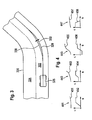
- Fig. 3 shows a process of curve cutting according to an embodiment of the present invention. Shown is a curve portion 320 of a lane having a first lane 322 and a second lane 324. A vehicle 326 moves on the first lane 322. The vehicle 326 may travel along a trajectory 328 that is centered in the first lane 322. According to the invention, a section trajectory 330 is determined, which enables a curve cutting with a lateral tray 332. In this case, the tray 332 characterizes a lateral shelf or a lateral distance from the center of the lane 328. Because of the lateral shelf 332, the section trajectory 330 runs on the inside of the curve of the middle of the lane 328.
- the lateral shelf 332 can extend over the course of the sectional trajectory 330 and, for example, be greatest at the vertex of the curve portion 320.
- a size of the tray 332 starting from the beginning of the curve section 320, can increase continuously up to the vertex and then decrease continuously until the end of the curve section 320.
- the tray 332 may be "zero".
- an inventive algorithm ensure that when passing through the curve 320, the curvature of the trajectory 330 relative to the curve 328 systematically reduced and at the same time a certain distance 332 is maintained to the lane center.
- Curves are constructed in such a way that, after a straight line, the curvature value initially increases linearly with the arc length (curve entry with clotoids), then remains constant (arc with apex) or different curvatures are achieved, which are respectively connected to clotoid segments and then drop again (curve exit with clotoids ).
- the number of curve parameters for a curve is therefore not specified.
- the simplest curve consists of three segments (without the surrounding lines), an S-curve then consists of five segments (Klotoide - arc - Klotoide - arc - Klotoide).
- An opening or closing curve also consists of five segments (excluding the surrounding lines), all of which have the same curvature.
- curve curves that combine unbalanced and S-curves and therefore have a higher number of curve parameters. Therefore, the planning of the trajectory must be done individually for the successive curve segments.
- Fig. 4 shows a representation of four basic elements, according to different embodiments of the present invention, each shown with xy coordinates, in the upper part of the image and with corresponding curvature data, in the lower part of the image, representing the curvature course over the path.
- a first base element represents a curve input 441, a second base element an unbalanced curve 443, a third base element an S curve 445 and a fourth base element a curve exit 447.
- a curve input 441 the elements straight line, clothoid and circular arc are stapled together and at a curve exit 447 circular arc, clothoids and another straight line.
- An unbalanced curve 443 consists of a circular arc, a clothoid and a circular arc. This shows curves with the same signs of curvature that contract or widen.
- the S-curves 445 are composed of the same elements, with the difference that in the clothoid section the curvature has a zero crossing and the sign changes, but the curvature change still remains constant. For a simple right turn you need two basic elements.
- the first base element for the curve input preferably extends to half of the circular arc (vertex of the curve).
- trajectory planning has thus been reduced to six parameters for the curvature description (s 1 , K 1 ), (s 2 , K 2 ), and (s 3 , K 3 ) and the associated boundary conditions and the secondary conditions within the four basic elements .
- the boundary conditions must be used to ensure that the stapling of the basic elements in the xy description is continuous and differentiable. Also, in the sK description, continuity and sweeping the same yaw angle must be guaranteed. This keeps the modularization of the trajectory planning in the individual basic elements consistent.
- the boundary conditions ensure that the curvature is reduced and the shape of the curve is maintained.
- the planning within the basic elements is carried out to such an extent that, for curve cutting, a maximum lateral storage value from the center of the traffic lane at the vertex is selected as a parameterizable measure.
- the six free parameters are chosen so that they must be reached from the endpoint of the trajectory.
- a point is set which the trajectory to be generated for the curve input should intersect with the same yaw angle as the center lane of the lane at the curve vertex.
- the new intersection is achieved with a reduced maximum curvature and thus specifically reduces the lateral acceleration and increases ride comfort.
- a course of a trajectory 451 and a coordinate system with a curve 452 over the path are shown.
- the path s is plotted on the abscissa and the curvature ⁇ is plotted on the ordinate.
- the trajectory 451 has no curvature in a first region, a curvature rising in a central region, and a constant curvature value not equal to zero in an end region.
- the trajectory 453 has a constant curvature value not equal to zero in a first region, a curvature rising in a middle region, and a constant curvature value not equal to zero in an end region.
- the trajectory 455 has a constant first curvature value not equal to zero in a first range, a linearly increasing curvature in a middle range, and a constant second curvature value not equal to zero in an end range.
- the first and second curvature values have different signs because the direction of curvature of the S curve 445 reverses over the path.
- the trajectory 457 has a constant curvature value not equal to zero in a first region, a linearly decreasing curvature in a middle region and no curvature in an end region.
- curvature values can also have a negative sign.
- the central region of the curvature curves 454, 456 can also decrease linearly, ie in a linear manner, in general terms.
- a road pattern may be divided into the four basic elements, ie curve inputs 441, curve outputs 447 and curve sections of varying curvature, with equal (asymmetric curve section) curvature sign 443 and different (S curve section) curvature sign 445.
- the four base elements 441, 443, 445, 447 can each be composed of three geometric shapes, wherein a transition between two different curvature values is always a Klotoidensegment set to one to ensure steady curvature.
- the basic elements 441, 443, 445, 447 are each treated individually, that is, an algorithm is used to determine a trajectory with which the curve can be cut in a suitable manner, and lined up in accordance with the route. In order to ensure a seamless and smooth transition, certain constraints must be met for the treatment of the individual base elements 441, 443, 445, 447.
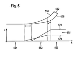
- Fig. 5 shows a curve cutting on the example of the curve input.
- a trajectory 528 In the upper image section, a trajectory 528, a planned section trajectory 530 and a lateral storage 532 are shown.
- the trajectory 528 may correspond to the actual curve, for example along the center of the traffic lane.
- the trajectory 528 is divided into three sections, wherein a first section has no curvature, a second section has a linearly increasing curvature, and a third section has a constant maximum curvature.
- the intersection trajectory 530 has a maximum curvature that is less than the maximum curvature of the trajectory 528.
- the repository 532 increases toward the end of the curve and has a value A_s at the endpoint of both trajectories 528, 530.
- the arc length s is plotted on the abscissa. This applies to the curvature curves 570, 572 but not to the trajectories 528, 530.
- a coordinate system is shown in which the abscissa represents the path s and the ordinate the curvature ⁇ . Shown are a first section 561, a second section 562 and a third section 563, which may correspond to the corresponding sections of the trajectory 528 or the section trajectory 530.
- a curvature profile 570 for the trajectory 528 and a curvature profile 572 for the sectional trajectory 530 are plotted in the coordinate system.
- both curvature curves 570, 572 are equal to zero.
- a length of the straight line of the curvature curve 572 for the sectional trajectory 530 in the first section 561 is shorter than the length of the straight line of the curvature curve 570 for the trajectory 528.
- the curvature course 570 has a smaller gradient than the curvature curve 572.
- the third section 563 is a reduction 575 of the maximum curvature in the curve 570, which is associated with the planned section trajectory 530, shown in comparison to the curvature 572.
- a curvature profile and a length of the clotid segment in the second section 562 and finally a length of the straight segment in the first segment 561 can be determined so that certain constraints are met, and start sections of the trajectories 528, 530 coincide in terms of filing and angular direction.
- the lengths of the three segments as well as the curvature of clothoids or circular arcs can thus be varied, for example for the basic element curve input consisting of straight line, clotide and circular arc Fig. 5 is shown.
- the respectively desired storage value A_s 532 in the curve vertex may depend on the curve speed and the maximum curvature of the curve.
- the first condition is that the finished planned base element can be inserted seamlessly into the trajectory course.
- Another condition is that the transitions at the seams are each smooth, which means that the intersection trajectory should cause the same yaw angle change in the vehicle as the trajectory on the roadway center.
- the steering angle should follow only natural movements, so the steering angle curve should increase and decrease continuously and approximately linearly in time, ie with constant steering speed.
- the planned intersection curve should always map the course of the route in order to ensure a meaningful course of the section trajectory 530.
- the last proviso is that the curve cutting with guaranteed reduced curvature and steering movement and the vehicle does not leave the lane at any time.
- Fig. 5 The effects on the individual curvature sections and on the trajectory course 530 are in Fig. 5 shown in sections 561, 562, 563.
- the third Section 563 reduces the maximum curve entrance curvature and maintains the segment length (similar course of the section trajectory).
- the Klotoidensegment extended in the second section 562 to ensure the smooth course at the seams (same yaw angle).
- the straight segment in the first section 561 is shortened so that the targeted storage point is reached.
- the only freely parameterizable values in this curve section are the length of the circular arc in the third section 563 and the length of the desired file 532 in the curve vertex A_s. There is always a solution with reduced maximum curve curvature.
- Trajectory planning can pass the lateral distance from the center of the lane, the planned trajectory curvature, and the planned angle to the center of the lane as a new default to the LKS controller. This data can still be compared with the lane information, from the in-vehicle video sensors to compensate for incorrect map information.
- FIGS. 6a and 6b are directed to further embodiments of the present invention, in which a start of a curve takes place.
- the approach of the curve takes place to minimize the Trajektorienradius, possibly with cutting, as described in the other embodiments.
- Fig. 6a shows a schematic representation of a curve trajectory 630, according to an embodiment of the present invention, in which a start of the curve takes place. In this case, the curve is approached in order to obtain a minimization of the curvature for the entire curve trajectory.
- a position 631 is a right steering to get to an outside position 632 of the lane.
- an inner vertex 633 is shown.
- At the end of the curve 634 an extreme extension of the curve followed by a return 635 in the middle of the lane. This allows a further minimization of curvature can be achieved, further minimized than without starting.
- a basic element consists of the six parameters (s 1 , K 1 ), (s 2 , K 2 ), and (s 3 , K 3 ). By varying these parameters, starting from the course of the route, a trajectory is generated which fulfills the required conditions on the xy and sK curves, as in FIG Fig. 7 shown.
- Fig. 6b shows a further schematic representation of in Fig. 6a shown curve trajectory 630, according to another embodiment of the present invention.
- the road section has a curve.
- the curve trajectory 630 runs in places on the outside lane. Further, the sectioning trajectory 330 shown in FIG Fig. 3 described embodiment can be determined. In the curve, a beginning of the actual curve KA and an end of the curve KE is marked.
- Curve trajectory 630 plots a starting point A, a first turning point of curvature WP1, a first foot point FP1, a vertex of curve IP, a second foot point FP2, and a second turning point of curvature WP2.
- the effective trajectory radius can be reduced by not having the bottoms FP1, FP2 of the curve trajectory 630 in the middle of the lane, as shown in FIG Fig. 3 is shown, but as far as possible be placed on the outer edge of the road, so that the connecting curve trajectory 630 gets a larger radius.
- the foot points FP1, FP2 must be placed simultaneously before the beginning of the curve KB and behind the end KE and thus extend the curve virtually.
- the foot points FP1, FP2 are correspondingly at the same time the trajectory points which come closest to the outer road side.
- the distance can be parameterized or, for example, also set by the driver. Similarly, the distance at the vertex of the curve IP, where the vehicle closest to the adjacent track (analogous to the determination of the apex of the section trajectory 330).
- the entire trajectory thus additionally includes in each case a segment of the retrieval bounded by the points A and WP1 and a segment of the recapture delimited by the points WP2 and E.
- the segment of the recovery is the approach of the curve, is first driven counter to the main curve direction to get to the outer edge of the lane. Ditto for re-catching in the middle of the lane.
- the curve segment for passing through the main curve ie between the first inflection point WP1 and the second inflection point WP2 of the curvature, therefore also lays a larger circular arc than the curve itself is long.
- the segment labeled Curve Segment may also be represented by one or more clothoid segments or other functional pieces. In the Fig. 6 described approach method can also serve the other embodiments analogously as an extension.
- the cut trajectory 330 would be replaced by the curve trajectory 630 with its additional clothoid and circular bottom segments.
- Fig. 7 shows an illustrated representation for the formulation of the boundary and secondary conditions.
- an xy curve of a track center 328 and a course of a planned trajectory 330 are shown.
- an s-kappa curve with a curve course 570 for the track center 328 and a curve 572 for the planned trajectory 330 is shown.
- connection conditions to the previous / following basic element must be fulfilled.
- the procedure is as follows.
- the base elements are identified by the curvature segments (straight line, clothoid, circular arc).
- the curve input is modified by minimizing curvature and segment lengths be adjusted.
- the calculated vertex is reached as the endpoint of the curve input trajectory, as shown in FIG Fig. 8 is shown.
- Fig. 8 shows a trajectory planning in the xy-coordinate system, wherein the planned trajectory T 330 emerges from the distance S 328.
- the basic requirement for this is that the trajectory T has the same starting point as the path S. This is ensured by the coordinate transformation, which ensures a continuous and differentiable xy curve in the coordinate origin.
- Max A x sgn ⁇ 3 ⁇ cos ⁇ e ⁇ A s .
- ⁇ E represents the yaw angle at the end point of the distance in the base element.
- the constraints on the xy curve are as follows.
- the maximum storage should be at the apex of the trajectory and also depend on the expected lateral acceleration and a human factor.
- the location of the vertex is determined by dividing the route into the basic elements. Test subjects showed that in the majority of cases the maximum lateral deposit was reached in the middle of the arc section. The basic elements are after this observation and thus also the vertices of the trajectory. The location of the vertex remains parameterizable in order to adapt the trajectory planning to different requirements / driver types.
- the choice of a circular arc length can be used. It is advisable always to keep constant the length of the segment which most affects the curve shape, ie has the greatest curvature. Depending on the base element, this condition can be used as a supplement if one degree of freedom is not treated by the remaining conditions.
- ⁇ 3 s is the curvature of the third segment.
- the specification of the RAS continues to give the continuity in the curvature, so is ⁇ 2 ⁇ ⁇ 3
- the boundary conditions result from the distribution of the distance and thus also the Trajektorienverlaufes in the four basic elements.
- the following measures have to be taken in the xy- and the s- ⁇ -course.
- the xy-course of the trajectory has to be continuous and differentiable like the track Fig. 9 is shown.
- the fulfillment of equations (4.8) and (4.9) ensures a steady course.
- the differentiability is achieved by fixing the xy curve of the trajectory of a following base element 901 at the correct angle to the preceding base element 903. These requirements are in Fig. 10 shown for the s-kappa course.
- Fig. 10 shows the boundary conditions in the xy curve of the trajectory.
- the fulfillment of equations (4.8) and (4.9) ensures a steady course.
- the differentiability is achieved by the xy-course of the trajectory of the subsequent base element 901 is tacked at the correct angle to the previous base element 903.
- the s- ⁇ -course should be continuous, whereby the first curvature value ⁇ 1 is fixed with the end curvature of the previous base element.
- the trajectory must continue to cover the same yaw angle as the distance of the base element, so that the starting and ending point of the base element are set at the correct angle.
- each of the three segments must be varied in length and end curvature according to the established boundary conditions and constraints, so that the conditions can be consistently applied to the four elements. So here's the implementation of the conditions to an algorithm described.
- the first part of a curve is always the curve input, which consists of a straight line with the parameterization (s 1 s , ⁇ 1 s ), a clothoid with (s 2 s , ⁇ 2 s ) and a circular arc with (s 3 s , ⁇ 3 s ).
- the three segments are described with end curvature and length, so that the Cartesian coordinates and yaw angle of the complete curve input trajectory can be calculated. It should be noted that in the formation of the base member, the first and third segment length be halved so that the curve sections before and after entering the curve can be attached in the correct length and thus the curve vertex lies on the half of the circular arc and represents the end point of the trajectory.
- a boundary condition is that the yaw angle at the endpoint of the trajectory is equal to that of the distance, see Equation (4.14).
- a limitation that may result from the length of s 1 s is that the given lateral offset can not be achieved. It must be at least as long that it can be used to cut the curve. Considering equation (4.19), the reason becomes apparent.
- the yaw angle condition says that with decreasing ⁇ 3 the length of the clotoids s 2 must increase. Curved cutting shortens the overall length of the base element, resulting in an additional shortening of s 1 .
- the length s 1 is therefore used in the determination of the curve-typical upper limit for the vertex offset A s, max .
- the zero position search obtains as a secondary condition ⁇ 3 ⁇ 3 s .
- Fig. 11 As a result of trajectory planning for the curve entrance 1101, the relative lateral shelf 1102, the curvature curve 1003 and the yaw angle curve 1104 are shown.
- the curve output consists mirror-symmetric to the curve input from a juxtaposition of the segments circular arc, clothoid and straight line.
- the problem of trajectory finding for the curve output is transformed and treated as curve input by interchanging the 1st and 3rd segments and reversing the clothoid accordingly.
- the segments are parameterized as a straight line (s 1 s , ⁇ 1 s ), a clothoid (s 2 s , ⁇ 2 s ), and a circular arc (s 3 s , ⁇ 3 s ).
- the new tray must be determined via the path for the LCS controller, it is necessary to transform the tray and path vector back after trajectory planning. For this purpose, the vectors are re-stored from back to front. The path vector must also be cleaned up from the offset so that the first entry lies in the origin of the coordinates. This applies accordingly for the curvature and yaw rate data.
- the transformed starting point of the cutting trajectory must lie on the straight segment of the curve center trace, the end point on the curve vertex, ie the end point of the previous curve segment.
- equation (4.25) As in the case of curve input, due to the independence of equation (4.25) from parameter s 1, this is solved before equation (4.25) is then explicitly solved for s 1 .
- s 1 can be determined by solving (4.24).
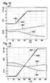
- Fig. 12 As a result of the trajectory planning, the route guide 1201, the relative lateral tray 1202, the curvature course 1203 and the yaw angle course 1204.
- unbalanced curve is here called a curve that has a sectionally constant curvature course not equal to zero.
- the geometric elements used are a circular arc (s 1 s , ⁇ 1 s ), a clothoid (s 2 s , ⁇ s ), and a second circular arc (s 3 s , ⁇ 3 s ).
- the curvatures ⁇ 1 s and ⁇ 3 s have the same sign.
- the curvature ⁇ 1 in the first circular arc segment of the trajectory is already predetermined by the previous trajectory segment.
- the four degrees of freedom remain in (s 1 , s 2 , s 3 , ⁇ 3 ) in order to produce the cutting curve.
- As conditions in addition to the above continuity conditions in the xy-course and s- ⁇ -course remain the yaw angle condition and the requirement that the waveform should be preserved.
- the parameters of both equations must now be determined independently of each other.
- the starting point of the trajectory is the vertex of the previous section trajectory, the end point is the new vertex, which is determined with the aid of A s, max .
- An unbalanced curve can be either an incoming or an opening curve.
- This degree of freedom can be used as a tuning parameter for the entry of curves, in order to additionally parameterize the planned trajectory for the test persons.
- the equation is to be solved by considering the constraint ⁇ 3 ⁇ 3 s .
- the length of the second arc segment s 3 was set to the length s 3 s .
- another parameter must be included, in analogy to the curve output this is the length of the first arc segment s 1 .
- the correct yaw angle is set over the length of the clothoid s 2 .
- the zero-point search for the unbalanced curve is thus composed of a zero position search in two variables, the solution to the problem consists of a synthesis of the solutions to the curve entry and exit curve.
- Fig. 13 As a result of trajectory planning for an unbalanced curve 1301, the relative lateral shelf 1302, the curvature 1303, and the yaw angle curve 1304 of an incoming curve.
- the S-curve differs from the unbalanced curve in that the curvatures of both circular arcs have different signs.
- the curve is parameterized with a circular arc (s 1 s , ⁇ 1 s ), a clothoid (s 2 s , ⁇ 2 s ), and a second arc (s 3 s , ⁇ 3 s ).
- the curvature ⁇ 1 of the first arc of the trajectory is already determined in the previous trajectory section. This leaves the four degrees of freedom (s 1 , s 2 , s 3 , ⁇ 3 ) to produce the trajectory.
- Other conditions besides the continuity conditions in the xy curve and the s-k curve are the yaw angle condition and the condition that the curve shape should be preserved.
- the formulation of this condition differs from the previous formulations, since in an S-curve, the circular arc pieces are often approximately point-symmetrical in the course of curvature and in the xy-course. Therefore, it does not make sense to keep one clot length constant while the other one would be altered because this would significantly deviate the trajectory shape from the curve shape.
- the parameters of both equations must again be determined dependent on each other, as in the case of the unbalanced curve.
- the equation is to be solved by considering the constraint ⁇ 3 ⁇ 3 s .
- Fig. 14 As a result of trajectory planning for an S-curve 1401, the relative lateral shelf 1402, the curvature 1403, and the yaw angle 1404 are shown.
- an exemplary embodiment comprises a "and / or" link between a first feature and a second feature
- this can be read so that the embodiment according to one embodiment, both the first feature and the second feature and according to another embodiment, either only the first Feature or only the second feature.
Landscapes
- Engineering & Computer Science (AREA)
- Transportation (AREA)
- Mechanical Engineering (AREA)
- Chemical & Material Sciences (AREA)
- Combustion & Propulsion (AREA)
- Automation & Control Theory (AREA)
- Steering Control In Accordance With Driving Conditions (AREA)
- Traffic Control Systems (AREA)
- Control Of Driving Devices And Active Controlling Of Vehicle (AREA)
- Navigation (AREA)
Applications Claiming Priority (2)
| Application Number | Priority Date | Filing Date | Title |
|---|---|---|---|
| DE102009047476A DE102009047476A1 (de) | 2009-12-04 | 2009-12-04 | Verfahren und Steuergerät zur Bestimmung einer Schnitttrajektorie eines Kurvenabschnitts einer Fahrbahn |
| PCT/EP2010/068530 WO2011067252A1 (de) | 2009-12-04 | 2010-11-30 | Verfahren und steuergerät zur bestimmung einer schnitttrajektorie eines kurvenabschnitts einer fahrbahn |
Publications (2)
| Publication Number | Publication Date |
|---|---|
| EP2507111A1 EP2507111A1 (de) | 2012-10-10 |
| EP2507111B1 true EP2507111B1 (de) | 2014-10-08 |
Family
ID=43587577
Family Applications (1)
| Application Number | Title | Priority Date | Filing Date |
|---|---|---|---|
| EP10790369.2A Not-in-force EP2507111B1 (de) | 2009-12-04 | 2010-11-30 | Verfahren und steuergerät zur bestimmung einer schnitttrajektorie eines kurvenabschnitts einer fahrbahn |
Country Status (6)
| Country | Link |
|---|---|
| US (1) | US9278712B2 (enExample) |
| EP (1) | EP2507111B1 (enExample) |
| JP (1) | JP2013513149A (enExample) |
| CN (1) | CN102741109B (enExample) |
| DE (1) | DE102009047476A1 (enExample) |
| WO (1) | WO2011067252A1 (enExample) |
Cited By (1)
| Publication number | Priority date | Publication date | Assignee | Title |
|---|---|---|---|---|
| US11110935B2 (en) | 2015-09-08 | 2021-09-07 | Thinkware Corporation | Curve guidance method, curve guidance apparatus, electronic apparatus and program stored in the computer-readable recording medium |
Families Citing this family (77)
| Publication number | Priority date | Publication date | Assignee | Title |
|---|---|---|---|---|
| JP5363906B2 (ja) * | 2009-08-05 | 2013-12-11 | 株式会社アドヴィックス | 車両の速度制御装置 |
| CN103729527A (zh) * | 2012-10-12 | 2014-04-16 | 上海市政工程设计研究总院(集团)有限公司 | 一种道路边线设计方法 |
| JP6026295B2 (ja) * | 2013-01-23 | 2016-11-16 | 株式会社デンソーアイティーラボラトリ | カーブ形状モデル化装置、方法及び車載用ナビゲーション装置 |
| JP5739465B2 (ja) * | 2013-02-14 | 2015-06-24 | 本田技研工業株式会社 | 車両の操舵制御装置 |
| DE102013203819A1 (de) * | 2013-03-06 | 2014-09-11 | Bayerische Motoren Werke Aktiengesellschaft | Fahrerassistenzsystem zur Unterstützung des Fahrers eines Kraftfahrzeuges beim Verlassen einer vorgegebenen Fahrspur |
| JP6161942B2 (ja) * | 2013-04-19 | 2017-07-12 | 株式会社デンソーアイティーラボラトリ | カーブ形状モデル化装置、車両情報処理システム、カーブ形状モデル化方法、及びカーブ形状モデル化プログラム |
| JP5783204B2 (ja) * | 2013-05-01 | 2015-09-24 | トヨタ自動車株式会社 | 運転支援装置および運転支援方法 |
| JP2015074425A (ja) * | 2013-10-11 | 2015-04-20 | 日産自動車株式会社 | 転舵制御装置及び転舵制御方法 |
| DE102013223000A1 (de) * | 2013-11-12 | 2015-05-13 | Robert Bosch Gmbh | Verfahren zum Ermitteln einer Fahrkurve, Steueranordnung zum Durchführen des Verfahrens und Fahrzeug mit einer derartigen Steueranordnung |
| US9090260B2 (en) | 2013-12-04 | 2015-07-28 | Mobileye Vision Technologies Ltd. | Image-based velocity control for a turning vehicle |
| DE102014200687A1 (de) * | 2014-01-16 | 2015-07-16 | Robert Bosch Gmbh | Verfahren zum Betreiben eines Fahrzeugs |
| US9244462B2 (en) * | 2014-05-30 | 2016-01-26 | Nissan North America, Inc. | Vehicle trajectory planning for autonomous vehicles |
| US9858487B2 (en) | 2015-02-19 | 2018-01-02 | Here Global B.V. | Method and apparatus for converting from an analytical curve road geometry to a clothoid road geometry |
| US10060749B2 (en) * | 2015-02-19 | 2018-08-28 | Here Global B.V. | Method and apparatus for creating a clothoid road geometry |
| EP3106369B1 (en) | 2015-06-16 | 2018-12-12 | Volvo Car Corporation | Method and system for safe steering assistance in a vehicle |
| US10684133B2 (en) | 2015-07-22 | 2020-06-16 | Honda Motor Co., Ltd. | Route generator, route generation method, and route generation program |
| DE102015216152A1 (de) | 2015-08-25 | 2017-03-02 | Conti Temic Microelectronic Gmbh | Spurhalteassistenzvorrichtung, Kraftfahrzeug mit einer solchen Spurhalteassistenzvorrichtung sowie ein Verfahren zur Spurhalteüberwachung |
| DE102016221171B4 (de) * | 2015-11-06 | 2022-10-06 | Ford Global Technologies, Llc | Verfahren und Vorrichtung zur Ermittlung von Fahrspurverlaufsdaten |
| JP6589608B2 (ja) * | 2015-12-04 | 2019-10-16 | 株式会社デンソー | 車両制御装置 |
| JP2017100652A (ja) * | 2015-12-04 | 2017-06-08 | 株式会社デンソー | 走行軌跡生成装置、走行軌跡生成方法 |
| US9974225B2 (en) | 2016-01-14 | 2018-05-22 | Cnh Industrial America Llc | System and method for generating and implementing an end-of-row turn path |
| US9968025B2 (en) | 2016-01-14 | 2018-05-15 | CNH Industrial American LLC | System and method for generating and implementing an end-of-row turn path |
| WO2017145555A1 (ja) * | 2016-02-26 | 2017-08-31 | 日立オートモティブシステムズ株式会社 | 走行制御装置及び走行制御システム |
| JP6525159B2 (ja) * | 2016-07-15 | 2019-06-05 | トヨタ自動車株式会社 | 車両用操舵支援装置 |
| US11235754B2 (en) * | 2016-08-23 | 2022-02-01 | Sanei Co., Ltd. | Travel trajectory preparation device, method, and program, and drive assist device and system |
| US10474158B2 (en) * | 2016-09-09 | 2019-11-12 | Nissan Motor Co., Ltd. | Vehicle travel control method and travel control device |
| WO2018061100A1 (ja) * | 2016-09-28 | 2018-04-05 | 本田技研工業株式会社 | 車両制御装置 |
| JP6485792B2 (ja) * | 2017-03-17 | 2019-03-20 | マツダ株式会社 | 運転支援制御装置 |
| JP6551866B2 (ja) * | 2017-03-17 | 2019-07-31 | マツダ株式会社 | 運転支援制御装置 |
| CN107340772B (zh) * | 2017-07-11 | 2020-05-22 | 北京超星未来科技有限公司 | 一种面向无人驾驶的拟人化参考轨迹规划方法 |
| DE102017212254A1 (de) | 2017-07-18 | 2019-01-24 | Volkswagen Aktiengesellschaft | Prädiktive Streckenführung eines Fahrzeugs |
| JP6814710B2 (ja) | 2017-08-10 | 2021-01-20 | 日立オートモティブシステムズ株式会社 | 車両運動制御装置及びその方法、並びに、目標軌道生成装置及びその方法 |
| DE102017215737B4 (de) * | 2017-09-07 | 2022-01-27 | Ford Global Technologies, Llc | Fahrerassistenzsystem |
| US10807599B2 (en) * | 2017-09-18 | 2020-10-20 | Baidu Usa Llc | Driving scenario based lane guidelines for path planning of autonomous driving vehicles |
| CN109583271B (zh) * | 2017-09-29 | 2020-11-06 | 杭州海康威视数字技术股份有限公司 | 一种对车道线进行拟合的方法、装置及终端 |
| JP7081117B2 (ja) * | 2017-11-06 | 2022-06-07 | いすゞ自動車株式会社 | 操舵制御装置及び操舵制御方法 |
| DE102017220486B4 (de) | 2017-11-16 | 2023-05-11 | Volkswagen Aktiengesellschaft | Verfahren zur Adaption einer vorbestimmten Referenzlinie für ein Kraftfahrzeug und Vorrichtung |
| JP7091670B2 (ja) * | 2018-01-18 | 2022-06-28 | 株式会社デンソー | 交差点内の走行軌道データ生成装置、交差点内の走行軌道データ生成プログラム及び記憶媒体 |
| CN108520120B (zh) * | 2018-03-19 | 2022-04-08 | 大连理工大学 | 一种道路路线平面线形设计的“两点”法 |
| US10745017B2 (en) * | 2018-06-07 | 2020-08-18 | GM Global Technology Operations LLC | Method and vehicle utilizing predictive road curvature in the transmission control module |
| DE102018212916A1 (de) * | 2018-08-02 | 2020-02-06 | Bayerische Motoren Werke Aktiengesellschaft | Bestimmung eines Verlaufs einer Fahrspur |
| JP7087884B2 (ja) * | 2018-09-26 | 2022-06-21 | トヨタ自動車株式会社 | 車両制御装置 |
| FR3089924B1 (fr) * | 2018-12-14 | 2021-09-10 | Renault Sas | Procédé et système de controle de conduite préventive |
| JP7083306B2 (ja) * | 2018-12-17 | 2022-06-10 | 本田技研工業株式会社 | 走行軌道決定処理及び自動運転装置 |
| CN110262509B (zh) | 2019-07-10 | 2022-06-28 | 百度在线网络技术(北京)有限公司 | 车辆自动驾驶方法和装置 |
| US11754408B2 (en) * | 2019-10-09 | 2023-09-12 | Argo AI, LLC | Methods and systems for topological planning in autonomous driving |
| DE102020103972A1 (de) | 2020-02-14 | 2021-08-19 | Bayerische Motoren Werke Aktiengesellschaft | Verfahren und System zum Unterstützen eines Fahrers eines Fahrzeugs beim Halten einer Fahrspur |
| DE102020105434A1 (de) * | 2020-03-02 | 2021-09-02 | Valeo Schalter Und Sensoren Gmbh | Verfahren zum betreiben eines fahrzeugs, parkassistenzsystem und fahrzeug |
| CN111736603B (zh) * | 2020-06-22 | 2023-06-09 | 广州赛特智能科技有限公司 | 一种无人驾驶清扫车及其长距离贴边清扫方法 |
| CN111923916B (zh) * | 2020-07-24 | 2022-03-29 | 江苏大学 | 一种基于视觉感知行为和anfis的仿人转向建模方法及转向控制系统 |
| CN112296766B (zh) * | 2020-10-28 | 2022-06-10 | 西北工业大学 | 一种整体叶盘叶片型面的数控柔性抛光方法 |
| CN112363504B (zh) * | 2020-11-06 | 2024-04-12 | 黑龙江惠达科技发展有限公司 | 一种农机无人驾驶调头方法 |
| US11738749B2 (en) * | 2020-11-09 | 2023-08-29 | GM Global Technology Operations LLC | Methods, systems, and apparatuses for scenario-based path and intervention adaptation for lane-keeping assist systems |
| US11579250B2 (en) * | 2020-12-23 | 2023-02-14 | Robert Bosch Gmbh | Lane boundary detection using radar signature trace data |
| KR102507804B1 (ko) * | 2020-12-24 | 2023-03-09 | 주식회사 라이드플럭스 | 자율주행 차량의 주행 경로 생성 방법, 장치 및 컴퓨터프로그램 |
| EP4306376A4 (en) * | 2021-03-11 | 2024-09-04 | Hitachi Astemo, Ltd. | VEHICLE CONTROL DEVICE, VEHICLE CONTROL METHOD, TARGET TRAJECTORY CALCULATION METHOD, AND VEHICLE |
| CN113076641B (zh) * | 2021-03-31 | 2022-09-20 | 同济大学 | 基于风险评估的智能车人机协同转向控制并行计算方法 |
| CN113296470B (zh) * | 2021-05-24 | 2022-10-21 | 浙江热刺激光技术有限公司 | 飞切轨迹规划方法、飞切控制方法和飞切系统 |
| CN113361118B (zh) * | 2021-06-17 | 2022-06-28 | 中国电建集团福建省电力勘测设计院有限公司 | 分节预制式曲线顶管的顶力计算方法 |
| DE102021116230A1 (de) | 2021-06-23 | 2022-12-29 | HELLA GmbH & Co. KGaA | Verfahren zur Projektion einer Führungslinie auf eine Fahrbahn |
| CN113525365A (zh) * | 2021-07-21 | 2021-10-22 | 上汽通用五菱汽车股份有限公司 | 道路规划方法、装置及计算机可读存储介质 |
| CN113379873B (zh) * | 2021-08-11 | 2021-11-09 | 北京赛目科技有限公司 | 一种道路曲线确定方法、装置、电子设备 |
| CN113815646B (zh) * | 2021-09-14 | 2023-05-30 | 上汽通用五菱汽车股份有限公司 | 车辆的智能驾驶方法、车辆和可读存储介质 |
| CN114537372A (zh) * | 2022-03-15 | 2022-05-27 | 吉林大学 | 一种铰接式车辆变道避障方法 |
| CN114818175B (zh) * | 2022-04-13 | 2024-09-24 | 南京航空航天大学 | 一种复杂曲面的偏移轨迹曲率修正方法 |
| CN115230734B (zh) * | 2022-06-28 | 2025-12-12 | 深圳市易成自动驾驶技术有限公司 | 基于螺旋线道路建模的车辆控制方法、装置、设备及存储介质 |
| JP7768073B2 (ja) * | 2022-08-30 | 2025-11-12 | 株式会社アイシン | 運転支援装置及びコンピュータプログラム |
| CN115571163A (zh) * | 2022-10-31 | 2023-01-06 | 北京领骏科技有限公司 | 一种自动驾驶轨迹控制方法及相关设备 |
| JP7868519B2 (ja) * | 2023-01-30 | 2026-06-02 | 株式会社アイシン | 運転支援装置及びコンピュータプログラム |
| US12389188B2 (en) | 2023-01-30 | 2025-08-12 | Microsoft Technology Licensing, Llc | Motion tracking calibration for wearable device |
| FR3147219A1 (fr) * | 2023-03-28 | 2024-10-04 | Renault S.A.S | Procédé de modification autonome d’une trajectoire d’un véhicule automobile, dispositif de commande de trajectoire pour véhicule automobile et véhicule automobile comprenant un tel dispositif. |
| US12522215B2 (en) * | 2023-03-31 | 2026-01-13 | Torc Robotics, Inc. | Lane change path generation using piecewise clothoid segments |
| CN117508173A (zh) * | 2023-12-14 | 2024-02-06 | 武汉光庭信息技术股份有限公司 | 一种基于行车轨迹曲率的车速控制方法和系统 |
| CN117655563B (zh) * | 2024-01-31 | 2024-05-28 | 成都沃特塞恩电子技术有限公司 | 激光切割路径规划方法、装置、电子设备及存储介质 |
| DE102024208149A1 (de) * | 2024-08-28 | 2026-03-05 | Volkswagen Aktiengesellschaft | Verfahren zum Betreiben eines autonomen Fahrzeugs und autonomes Fahrzeug |
| DE102025100445A1 (de) * | 2025-01-08 | 2026-07-09 | Valeo Schalter Und Sensoren Gmbh | Steuersystem zum fahren in einer kurve einer fahrbahn |
| CN121685616A (zh) * | 2025-11-07 | 2026-03-17 | 济南邦德激光股份有限公司 | 一种跑道图形的扫描路径规划方法及规划设备 |
Family Cites Families (19)
| Publication number | Priority date | Publication date | Assignee | Title |
|---|---|---|---|---|
| US5375059A (en) * | 1990-02-05 | 1994-12-20 | Caterpillar Inc. | Vehicle position determination system and method |
| US5838562A (en) * | 1990-02-05 | 1998-11-17 | Caterpillar Inc. | System and a method for enabling a vehicle to track a preset path |
| JP3572876B2 (ja) | 1997-07-15 | 2004-10-06 | トヨタ自動車株式会社 | 車両用走行制御装置 |
| JPH11144185A (ja) * | 1997-09-03 | 1999-05-28 | Honda Motor Co Ltd | 自動運転制御誘導システム |
| US7089162B2 (en) * | 2001-11-07 | 2006-08-08 | Harman International Industries, Incorporated | Navigation map creation system |
| DE10256770A1 (de) * | 2002-12-05 | 2004-06-17 | Bayerische Motoren Werke Ag | Verfahren zum Lenken eines rückwärts in eine Parklücke einzuparkenden Fahrzeugs |
| KR20060049706A (ko) * | 2004-07-20 | 2006-05-19 | 아이신세이끼가부시끼가이샤 | 차량의 레인주행지원장치 |
| DE102005025387A1 (de) | 2004-09-30 | 2006-05-04 | Daimlerchrysler Ag | Verfahren und Vorrichtung zur Fahrerwahrnung bzw. zum aktiven Eingreifen in die Fahrdynamik, falls ein Verlassen der Fahrspur droht |
| JP4494162B2 (ja) * | 2004-10-15 | 2010-06-30 | 富士通テン株式会社 | 運転支援装置 |
| US7957893B2 (en) * | 2004-11-30 | 2011-06-07 | Dash Navigation, Inc. | Methods and systems for deducing road geometry and connectivity |
| DE102005048014A1 (de) * | 2005-10-07 | 2007-04-12 | Robert Bosch Gmbh | Fahrerassistenzsystem |
| DE102005056211A1 (de) | 2005-11-25 | 2007-06-06 | Robert Bosch Gmbh | Verfahren zur Steuerung der Querbewegung eines Fahrzeugs |
| JP4648335B2 (ja) * | 2007-01-10 | 2011-03-09 | 独立行政法人科学技術振興機構 | 車両走行用仮想試験を行うシステム及びプログラム |
| DE102008003666A1 (de) * | 2008-01-09 | 2009-07-16 | Robert Bosch Gmbh | Verfahren für die Steuerung eines Fahrerassistenzsystems und Fahrerassistenzsystem |
| DE102008022606A1 (de) | 2008-05-08 | 2009-11-12 | Man Nutzfahrzeuge Aktiengesellschaft | Spurführungssystem |
| US8862436B2 (en) * | 2008-06-24 | 2014-10-14 | Landmark Graphics Corporation | Systems and methods for modeling wellbore trajectories |
| US8099214B2 (en) * | 2009-02-09 | 2012-01-17 | GM Global Technology Operations LLC | Path planning for autonomous parking |
| WO2011086698A1 (ja) * | 2010-01-18 | 2011-07-21 | トヨタ自動車株式会社 | 車両制御装置 |
| DE102010042048B4 (de) * | 2010-10-06 | 2020-11-12 | Robert Bosch Gmbh | Vorrichtung und Verfahren zur Unterstützung eines Fahrers eines Kraftfahrzeugs bei einem Fahrmanöver |
-
2009
- 2009-12-04 DE DE102009047476A patent/DE102009047476A1/de not_active Withdrawn
-
2010
- 2010-11-30 CN CN201080055137.7A patent/CN102741109B/zh active Active
- 2010-11-30 WO PCT/EP2010/068530 patent/WO2011067252A1/de not_active Ceased
- 2010-11-30 EP EP10790369.2A patent/EP2507111B1/de not_active Not-in-force
- 2010-11-30 US US13/513,152 patent/US9278712B2/en active Active
- 2010-11-30 JP JP2012541462A patent/JP2013513149A/ja active Pending
Cited By (2)
| Publication number | Priority date | Publication date | Assignee | Title |
|---|---|---|---|---|
| US11110935B2 (en) | 2015-09-08 | 2021-09-07 | Thinkware Corporation | Curve guidance method, curve guidance apparatus, electronic apparatus and program stored in the computer-readable recording medium |
| DE102016217125B4 (de) | 2015-09-08 | 2022-11-03 | Thinkware Corporation | Kurvenführungsverfahren, Kurvenführungsgerät, elektronisches Gerät und auf dem computerlesbaren Aufnahmemedium gespeichertes Programm |
Also Published As
| Publication number | Publication date |
|---|---|
| JP2013513149A (ja) | 2013-04-18 |
| DE102009047476A1 (de) | 2011-06-09 |
| US9278712B2 (en) | 2016-03-08 |
| WO2011067252A1 (de) | 2011-06-09 |
| CN102741109A (zh) | 2012-10-17 |
| US20130006473A1 (en) | 2013-01-03 |
| CN102741109B (zh) | 2016-01-13 |
| EP2507111A1 (de) | 2012-10-10 |
Similar Documents
| Publication | Publication Date | Title |
|---|---|---|
| WO2011067252A1 (de) | Verfahren und steuergerät zur bestimmung einer schnitttrajektorie eines kurvenabschnitts einer fahrbahn | |
| DE112020000283B4 (de) | Fahrzeugsteuervorrichtung | |
| EP2091803B1 (de) | Verfahren zum rückwärtigen einparken eines fahrzeugs und einparkhilfesystem hierfür | |
| DE102009042915B4 (de) | Lenksteuervorrichtung für ein Fahrzeug | |
| WO2016180596A1 (de) | Bestimmen einer trajektorie für ein fahrzeug | |
| EP1421568B1 (de) | Verfahren zur bestimmung einer modellfahrbahn | |
| DE102005062084A1 (de) | Verfahren zum Lenken eines Fahrzeugs in eine Parklücke und Einparkhilfeeinrichtung | |
| DE102016201667B4 (de) | Verfahren zum Bestimmen einer Solltrajektorie für einen ersten Verkehrsteilnehmer, insbesondere für ein Kraftfahrzeug, für einen Streckenabschnitt | |
| DE102018106713A1 (de) | Verfahren zum Steuern eines Fahrzeugspurwechsels, Vorrichtung zum Steuern eines Fahrzeugspurwechsels und dazugehörige Einrichtungen | |
| EP3488419B1 (de) | Fahrassistenzverfahren, fahrassistenzsystem und fahrzeug | |
| DE112018007128B4 (de) | Routenerzeugungsvorrichtung, routenerzeugungsverfahren und fahrsteuerungsvorrichtung | |
| EP1844373B1 (de) | Verfahren zur kursprädiktion in fahrerassistenzsystemen für kraftfahrzeuge | |
| DE102016111691A1 (de) | Halbautonomes Fahrzeug und Verfahren zum Steuern eines halbautonomen Fahrzeugs | |
| DE102015108605A1 (de) | Fahrzeugspurwechselpfad-Planungsalgorithmus für ein autonom-fahrendes Fahrzeug | |
| DE102017004651A1 (de) | Verfahren zur Trajektorienplanung | |
| DE112019006872T5 (de) | Fahrzeugsteuervorrichtung und Fahrzeugsteuerverfahren | |
| DE102018204101A1 (de) | Verfahren und Vorrichtung zur Planung einer Trajektorie für die Längs- und/oder Querführung eines Fahrzeugs | |
| DE102018123896A1 (de) | Verfahren zum Betreiben eines wenigstens teilweise automatisierten Fahrzeugs | |
| DE102017205040A1 (de) | Verfahren zur Planung von kombinierter Längs- und Querbewegung für Fahrzeuge | |
| WO2020193490A1 (de) | Verfahren und fahrerassistenzsystem zur unterstützung eines fahrers eines fahrzeugs bei einem einparkmanöver in eine längsparklücke | |
| WO2023066906A1 (de) | Verfahren zum bestimmen einer soll-trajektorie eines zumindest teilweise automatisiert betriebenen kraftfahrzeugs auf einer einspurigen fahrbahn, computerprogrammprodukt sowie assistenzsystem | |
| DE102012011301A1 (de) | Die Erfindung bezieht sich auf ein Verfahren zur Steuerung eines Spurhalteassistenten für ein Kraftfahrzeug | |
| DE102010007598A1 (de) | Verfahren und Vorrichtung zur selbsttätigen Querführung eines Fahrzeuges | |
| DE102017220486B4 (de) | Verfahren zur Adaption einer vorbestimmten Referenzlinie für ein Kraftfahrzeug und Vorrichtung | |
| EP2871115B1 (de) | Verfahren zum ermitteln einer fahrkurve, steueranordnung zum durchführen des verfahrens und fahrzeug mit einer derartigen steueranordnung |
Legal Events
| Date | Code | Title | Description |
|---|---|---|---|
| PUAI | Public reference made under article 153(3) epc to a published international application that has entered the european phase |
Free format text: ORIGINAL CODE: 0009012 |
|
| 17P | Request for examination filed |
Effective date: 20120704 |
|
| AK | Designated contracting states |
Kind code of ref document: A1 Designated state(s): AL AT BE BG CH CY CZ DE DK EE ES FI FR GB GR HR HU IE IS IT LI LT LU LV MC MK MT NL NO PL PT RO RS SE SI SK SM TR |
|
| DAX | Request for extension of the european patent (deleted) | ||
| GRAP | Despatch of communication of intention to grant a patent |
Free format text: ORIGINAL CODE: EPIDOSNIGR1 |
|
| RIC1 | Information provided on ipc code assigned before grant |
Ipc: B62D 15/02 20060101ALI20140410BHEP Ipc: B62D 1/28 20060101AFI20140410BHEP Ipc: B60W 30/045 20120101ALI20140410BHEP Ipc: B60W 30/12 20060101ALI20140410BHEP |
|
| INTG | Intention to grant announced |
Effective date: 20140502 |
|
| GRAS | Grant fee paid |
Free format text: ORIGINAL CODE: EPIDOSNIGR3 |
|
| GRAA | (expected) grant |
Free format text: ORIGINAL CODE: 0009210 |
|
| AK | Designated contracting states |
Kind code of ref document: B1 Designated state(s): AL AT BE BG CH CY CZ DE DK EE ES FI FR GB GR HR HU IE IS IT LI LT LU LV MC MK MT NL NO PL PT RO RS SE SI SK SM TR |
|
| REG | Reference to a national code |
Ref country code: GB Ref legal event code: FG4D Free format text: NOT ENGLISH |
|
| REG | Reference to a national code |
Ref country code: AT Ref legal event code: REF Ref document number: 690415 Country of ref document: AT Kind code of ref document: T Effective date: 20141015 Ref country code: CH Ref legal event code: EP |
|
| REG | Reference to a national code |
Ref country code: IE Ref legal event code: FG4D Free format text: LANGUAGE OF EP DOCUMENT: GERMAN |
|
| REG | Reference to a national code |
Ref country code: DE Ref legal event code: R096 Ref document number: 502010008046 Country of ref document: DE Effective date: 20141120 |
|
| REG | Reference to a national code |
Ref country code: NL Ref legal event code: VDEP Effective date: 20141008 |
|
| REG | Reference to a national code |
Ref country code: LT Ref legal event code: MG4D |
|
| PG25 | Lapsed in a contracting state [announced via postgrant information from national office to epo] |
Ref country code: NL Free format text: LAPSE BECAUSE OF FAILURE TO SUBMIT A TRANSLATION OF THE DESCRIPTION OR TO PAY THE FEE WITHIN THE PRESCRIBED TIME-LIMIT Effective date: 20141008 |
|
| PG25 | Lapsed in a contracting state [announced via postgrant information from national office to epo] |
Ref country code: NO Free format text: LAPSE BECAUSE OF FAILURE TO SUBMIT A TRANSLATION OF THE DESCRIPTION OR TO PAY THE FEE WITHIN THE PRESCRIBED TIME-LIMIT Effective date: 20150108 Ref country code: LT Free format text: LAPSE BECAUSE OF FAILURE TO SUBMIT A TRANSLATION OF THE DESCRIPTION OR TO PAY THE FEE WITHIN THE PRESCRIBED TIME-LIMIT Effective date: 20141008 Ref country code: ES Free format text: LAPSE BECAUSE OF FAILURE TO SUBMIT A TRANSLATION OF THE DESCRIPTION OR TO PAY THE FEE WITHIN THE PRESCRIBED TIME-LIMIT Effective date: 20141008 Ref country code: PT Free format text: LAPSE BECAUSE OF FAILURE TO SUBMIT A TRANSLATION OF THE DESCRIPTION OR TO PAY THE FEE WITHIN THE PRESCRIBED TIME-LIMIT Effective date: 20150209 Ref country code: IS Free format text: LAPSE BECAUSE OF FAILURE TO SUBMIT A TRANSLATION OF THE DESCRIPTION OR TO PAY THE FEE WITHIN THE PRESCRIBED TIME-LIMIT Effective date: 20150208 Ref country code: FI Free format text: LAPSE BECAUSE OF FAILURE TO SUBMIT A TRANSLATION OF THE DESCRIPTION OR TO PAY THE FEE WITHIN THE PRESCRIBED TIME-LIMIT Effective date: 20141008 |
|
| PG25 | Lapsed in a contracting state [announced via postgrant information from national office to epo] |
Ref country code: LV Free format text: LAPSE BECAUSE OF FAILURE TO SUBMIT A TRANSLATION OF THE DESCRIPTION OR TO PAY THE FEE WITHIN THE PRESCRIBED TIME-LIMIT Effective date: 20141008 Ref country code: RS Free format text: LAPSE BECAUSE OF FAILURE TO SUBMIT A TRANSLATION OF THE DESCRIPTION OR TO PAY THE FEE WITHIN THE PRESCRIBED TIME-LIMIT Effective date: 20141008 Ref country code: GR Free format text: LAPSE BECAUSE OF FAILURE TO SUBMIT A TRANSLATION OF THE DESCRIPTION OR TO PAY THE FEE WITHIN THE PRESCRIBED TIME-LIMIT Effective date: 20150109 Ref country code: SE Free format text: LAPSE BECAUSE OF FAILURE TO SUBMIT A TRANSLATION OF THE DESCRIPTION OR TO PAY THE FEE WITHIN THE PRESCRIBED TIME-LIMIT Effective date: 20141008 Ref country code: HR Free format text: LAPSE BECAUSE OF FAILURE TO SUBMIT A TRANSLATION OF THE DESCRIPTION OR TO PAY THE FEE WITHIN THE PRESCRIBED TIME-LIMIT Effective date: 20141008 Ref country code: CY Free format text: LAPSE BECAUSE OF FAILURE TO SUBMIT A TRANSLATION OF THE DESCRIPTION OR TO PAY THE FEE WITHIN THE PRESCRIBED TIME-LIMIT Effective date: 20141008 Ref country code: PL Free format text: LAPSE BECAUSE OF FAILURE TO SUBMIT A TRANSLATION OF THE DESCRIPTION OR TO PAY THE FEE WITHIN THE PRESCRIBED TIME-LIMIT Effective date: 20141008 |
|
| PG25 | Lapsed in a contracting state [announced via postgrant information from national office to epo] |
Ref country code: BE Free format text: LAPSE BECAUSE OF NON-PAYMENT OF DUE FEES Effective date: 20141130 |
|
| REG | Reference to a national code |
Ref country code: CH Ref legal event code: PL |
|
| REG | Reference to a national code |
Ref country code: DE Ref legal event code: R097 Ref document number: 502010008046 Country of ref document: DE |
|
| PG25 | Lapsed in a contracting state [announced via postgrant information from national office to epo] |
Ref country code: SK Free format text: LAPSE BECAUSE OF FAILURE TO SUBMIT A TRANSLATION OF THE DESCRIPTION OR TO PAY THE FEE WITHIN THE PRESCRIBED TIME-LIMIT Effective date: 20141008 Ref country code: DK Free format text: LAPSE BECAUSE OF FAILURE TO SUBMIT A TRANSLATION OF THE DESCRIPTION OR TO PAY THE FEE WITHIN THE PRESCRIBED TIME-LIMIT Effective date: 20141008 Ref country code: LI Free format text: LAPSE BECAUSE OF NON-PAYMENT OF DUE FEES Effective date: 20141130 Ref country code: RO Free format text: LAPSE BECAUSE OF FAILURE TO SUBMIT A TRANSLATION OF THE DESCRIPTION OR TO PAY THE FEE WITHIN THE PRESCRIBED TIME-LIMIT Effective date: 20141008 Ref country code: CH Free format text: LAPSE BECAUSE OF NON-PAYMENT OF DUE FEES Effective date: 20141130 Ref country code: MC Free format text: LAPSE BECAUSE OF FAILURE TO SUBMIT A TRANSLATION OF THE DESCRIPTION OR TO PAY THE FEE WITHIN THE PRESCRIBED TIME-LIMIT Effective date: 20141008 Ref country code: CZ Free format text: LAPSE BECAUSE OF FAILURE TO SUBMIT A TRANSLATION OF THE DESCRIPTION OR TO PAY THE FEE WITHIN THE PRESCRIBED TIME-LIMIT Effective date: 20141008 Ref country code: EE Free format text: LAPSE BECAUSE OF FAILURE TO SUBMIT A TRANSLATION OF THE DESCRIPTION OR TO PAY THE FEE WITHIN THE PRESCRIBED TIME-LIMIT Effective date: 20141008 |
|
| PLBE | No opposition filed within time limit |
Free format text: ORIGINAL CODE: 0009261 |
|
| STAA | Information on the status of an ep patent application or granted ep patent |
Free format text: STATUS: NO OPPOSITION FILED WITHIN TIME LIMIT |
|
| REG | Reference to a national code |
Ref country code: IE Ref legal event code: MM4A |
|
| REG | Reference to a national code |
Ref country code: FR Ref legal event code: ST Effective date: 20150731 |
|
| PG25 | Lapsed in a contracting state [announced via postgrant information from national office to epo] |
Ref country code: IT Free format text: LAPSE BECAUSE OF FAILURE TO SUBMIT A TRANSLATION OF THE DESCRIPTION OR TO PAY THE FEE WITHIN THE PRESCRIBED TIME-LIMIT Effective date: 20141008 |
|
| 26N | No opposition filed |
Effective date: 20150709 |
|
| GBPC | Gb: european patent ceased through non-payment of renewal fee |
Effective date: 20150108 |
|
| PG25 | Lapsed in a contracting state [announced via postgrant information from national office to epo] |
Ref country code: GB Free format text: LAPSE BECAUSE OF NON-PAYMENT OF DUE FEES Effective date: 20150108 Ref country code: IE Free format text: LAPSE BECAUSE OF NON-PAYMENT OF DUE FEES Effective date: 20141130 |
|
| PG25 | Lapsed in a contracting state [announced via postgrant information from national office to epo] |
Ref country code: FR Free format text: LAPSE BECAUSE OF NON-PAYMENT OF DUE FEES Effective date: 20141208 |
|
| PG25 | Lapsed in a contracting state [announced via postgrant information from national office to epo] |
Ref country code: SI Free format text: LAPSE BECAUSE OF FAILURE TO SUBMIT A TRANSLATION OF THE DESCRIPTION OR TO PAY THE FEE WITHIN THE PRESCRIBED TIME-LIMIT Effective date: 20141008 |
|
| PG25 | Lapsed in a contracting state [announced via postgrant information from national office to epo] |
Ref country code: SM Free format text: LAPSE BECAUSE OF FAILURE TO SUBMIT A TRANSLATION OF THE DESCRIPTION OR TO PAY THE FEE WITHIN THE PRESCRIBED TIME-LIMIT Effective date: 20141008 |
|
| PG25 | Lapsed in a contracting state [announced via postgrant information from national office to epo] |
Ref country code: BG Free format text: LAPSE BECAUSE OF FAILURE TO SUBMIT A TRANSLATION OF THE DESCRIPTION OR TO PAY THE FEE WITHIN THE PRESCRIBED TIME-LIMIT Effective date: 20141008 |
|
| PG25 | Lapsed in a contracting state [announced via postgrant information from national office to epo] |
Ref country code: HU Free format text: LAPSE BECAUSE OF FAILURE TO SUBMIT A TRANSLATION OF THE DESCRIPTION OR TO PAY THE FEE WITHIN THE PRESCRIBED TIME-LIMIT; INVALID AB INITIO Effective date: 20101130 Ref country code: TR Free format text: LAPSE BECAUSE OF FAILURE TO SUBMIT A TRANSLATION OF THE DESCRIPTION OR TO PAY THE FEE WITHIN THE PRESCRIBED TIME-LIMIT Effective date: 20141008 Ref country code: MT Free format text: LAPSE BECAUSE OF FAILURE TO SUBMIT A TRANSLATION OF THE DESCRIPTION OR TO PAY THE FEE WITHIN THE PRESCRIBED TIME-LIMIT Effective date: 20141008 Ref country code: LU Free format text: LAPSE BECAUSE OF NON-PAYMENT OF DUE FEES Effective date: 20141130 |
|
| REG | Reference to a national code |
Ref country code: AT Ref legal event code: MM01 Ref document number: 690415 Country of ref document: AT Kind code of ref document: T Effective date: 20151130 |
|
| PG25 | Lapsed in a contracting state [announced via postgrant information from national office to epo] |
Ref country code: AT Free format text: LAPSE BECAUSE OF NON-PAYMENT OF DUE FEES Effective date: 20151130 |
|
| PG25 | Lapsed in a contracting state [announced via postgrant information from national office to epo] |
Ref country code: MK Free format text: LAPSE BECAUSE OF FAILURE TO SUBMIT A TRANSLATION OF THE DESCRIPTION OR TO PAY THE FEE WITHIN THE PRESCRIBED TIME-LIMIT Effective date: 20141008 |
|
| PG25 | Lapsed in a contracting state [announced via postgrant information from national office to epo] |
Ref country code: AL Free format text: LAPSE BECAUSE OF FAILURE TO SUBMIT A TRANSLATION OF THE DESCRIPTION OR TO PAY THE FEE WITHIN THE PRESCRIBED TIME-LIMIT Effective date: 20141008 |
|
| REG | Reference to a national code |
Ref country code: DE Ref legal event code: R084 Ref document number: 502010008046 Country of ref document: DE |
|
| PGFP | Annual fee paid to national office [announced via postgrant information from national office to epo] |
Ref country code: DE Payment date: 20250122 Year of fee payment: 15 |
|
| PGFP | Annual fee paid to national office [announced via postgrant information from national office to epo] |
Ref country code: MK Payment date: 20250604 Year of fee payment: 16 |
|
| REG | Reference to a national code |
Ref country code: DE Ref legal event code: R119 Ref document number: 502010008046 Country of ref document: DE |